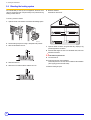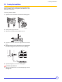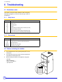
1
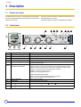
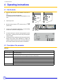
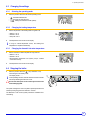
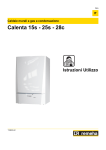
SOLNEO EN Gas fired condensing boiler SGC 24 SOL C001764 User Guide 300017555-001-C . Contents 1 Introduction . . . . . . . . . . . . . . . . . . . . . . . . . . . . . . . . . . . . . . . . . . . . . . . . . . . . . . . . . . . . . . . . . . . . . . . . . . . . .3 1.1 1.2 Symbols and abbreviations . . . . . . . . . . . . . . . . . . . . . . . . . . . . . . . . . . . . . . . . . . . . . . . . . . . . . . . . . . . . . . . . . . . . . . . . . . . . . . . .3 General. . . . . . . . . . . . . . . . . . . . . . . . . . . . . . . . . . . . . . . . . . . . . . . . . . . . . . . . . . . . . . . . . . . . . . . . . . . . . . . . . . . . . . . . . . . . . . . .3 1.2.1 Manufacturer's liability . . . . . . . . . . . . . . . . . . . . . . . . . . . . . . . . . . . . . . . . . . . . . . . . . . . . . . . . . . . . . . . . . . . . . . . . . . . . . .3 1.2.2 Installer's liability . . . . . . . . . . . . . . . . . . . . . . . . . . . . . . . . . . . . . . . . . . . . . . . . . . . . . . . . . . . . . . . . . . . . . . . . . . . . . . . . . .3 1.2.3 User's liability . . . . . . . . . . . . . . . . . . . . . . . . . . . . . . . . . . . . . . . . . . . . . . . . . . . . . . . . . . . . . . . . . . . . . . . . . . . . . . . . . . . . .3 1.3 Certifications. . . . . . . . . . . . . . . . . . . . . . . . . . . . . . . . . . . . . . . . . . . . . . . . . . . . . . . . . . . . . . . . . . . . . . . . . . . . . . . . . . . . . . . . . . . .4 2 Safety instructions and recommendations. . . . . . . . . . . . . . . . . . . . . . . . . . . . . . . . . . . . . . . . . . . . . . . . . . . .5 2.1 Safety instructions . . . . . . . . . . . . . . . . . . . . . . . . . . . . . . . . . . . . . . . . . . . . . . . . . . . . . . . . . . . . . . . . . . . . . . . . . . . . . . . . . . . . . . .5 2.1.1 Fire hazard . . . . . . . . . . . . . . . . . . . . . . . . . . . . . . . . . . . . . . . . . . . . . . . . . . . . . . . . . . . . . . . . . . . . . . . . . . . . . . . . . . . . . . .5 2.1.2 Risk of being burnt . . . . . . . . . . . . . . . . . . . . . . . . . . . . . . . . . . . . . . . . . . . . . . . . . . . . . . . . . . . . . . . . . . . . . . . . . . . . . . . . .5 2.2 Recommendations . . . . . . . . . . . . . . . . . . . . . . . . . . . . . . . . . . . . . . . . . . . . . . . . . . . . . . . . . . . . . . . . . . . . . . . . . . . . . . . . . . . . . . .5 3 Description. . . . . . . . . . . . . . . . . . . . . . . . . . . . . . . . . . . . . . . . . . . . . . . . . . . . . . . . . . . . . . . . . . . . . . . . . . . . . .6 3.1 3.2 3.3 4 General description . . . . . . . . . . . . . . . . . . . . . . . . . . . . . . . . . . . . . . . . . . . . . . . . . . . . . . . . . . . . . . . . . . . . . . . . . . . . . . . . . . . . . .6 Control panel . . . . . . . . . . . . . . . . . . . . . . . . . . . . . . . . . . . . . . . . . . . . . . . . . . . . . . . . . . . . . . . . . . . . . . . . . . . . . . . . . . . . . . . . . . .6 Parameter display - Diemasol A solar regulator . . . . . . . . . . . . . . . . . . . . . . . . . . . . . . . . . . . . . . . . . . . . . . . . . . . . . . . . . . . . . . . . .7 Operating instructions . . . . . . . . . . . . . . . . . . . . . . . . . . . . . . . . . . . . . . . . . . . . . . . . . . . . . . . . . . . . . . . . . . . .8 4.1 4.2 4.3 Start the boiler . . . . . . . . . . . . . . . . . . . . . . . . . . . . . . . . . . . . . . . . . . . . . . . . . . . . . . . . . . . . . . . . . . . . . . . . . . . . . . . . . . . . . . . . . .8 Description of the parameters . . . . . . . . . . . . . . . . . . . . . . . . . . . . . . . . . . . . . . . . . . . . . . . . . . . . . . . . . . . . . . . . . . . . . . . . . . . . . .8 Changing the settings. . . . . . . . . . . . . . . . . . . . . . . . . . . . . . . . . . . . . . . . . . . . . . . . . . . . . . . . . . . . . . . . . . . . . . . . . . . . . . . . . . . . .9 4.3.1 Selecting the operating mode . . . . . . . . . . . . . . . . . . . . . . . . . . . . . . . . . . . . . . . . . . . . . . . . . . . . . . . . . . . . . . . . . . . . . . . .9 4.3.2 Changing the heating temperature. . . . . . . . . . . . . . . . . . . . . . . . . . . . . . . . . . . . . . . . . . . . . . . . . . . . . . . . . . . . . . . . . . . . .9 4.3.3 Changing the domestic hot water temperature . . . . . . . . . . . . . . . . . . . . . . . . . . . . . . . . . . . . . . . . . . . . . . . . . . . . . . . . . . .9 4.4 Stopping the boiler . . . . . . . . . . . . . . . . . . . . . . . . . . . . . . . . . . . . . . . . . . . . . . . . . . . . . . . . . . . . . . . . . . . . . . . . . . . . . . . . . . . . . . .9 4.5 Prolonged absence. . . . . . . . . . . . . . . . . . . . . . . . . . . . . . . . . . . . . . . . . . . . . . . . . . . . . . . . . . . . . . . . . . . . . . . . . . . . . . . . . . . . . .10 4.5.1 Switching off the appliance . . . . . . . . . . . . . . . . . . . . . . . . . . . . . . . . . . . . . . . . . . . . . . . . . . . . . . . . . . . . . . . . . . . . . . . . .10 4.5.2 Antifreeze protection . . . . . . . . . . . . . . . . . . . . . . . . . . . . . . . . . . . . . . . . . . . . . . . . . . . . . . . . . . . . . . . . . . . . . . . . . . . . . .10 5 Checking and maintenance . . . . . . . . . . . . . . . . . . . . . . . . . . . . . . . . . . . . . . . . . . . . . . . . . . . . . . . . . . . . . . .11 5.1 5.2 5.3 5.4 5.5 6 General instructions . . . . . . . . . . . . . . . . . . . . . . . . . . . . . . . . . . . . . . . . . . . . . . . . . . . . . . . . . . . . . . . . . . . . . . . . . . . . . . . . . . . . .11 Periodic checks . . . . . . . . . . . . . . . . . . . . . . . . . . . . . . . . . . . . . . . . . . . . . . . . . . . . . . . . . . . . . . . . . . . . . . . . . . . . . . . . . . . . . . . .11 Topping up the boiler with water (If the option is connected) . . . . . . . . . . . . . . . . . . . . . . . . . . . . . . . . . . . . . . . . . . . . . . . . . . . . . .11 Bleeding the heating system . . . . . . . . . . . . . . . . . . . . . . . . . . . . . . . . . . . . . . . . . . . . . . . . . . . . . . . . . . . . . . . . . . . . . . . . . . . . . .12 Draining the installation . . . . . . . . . . . . . . . . . . . . . . . . . . . . . . . . . . . . . . . . . . . . . . . . . . . . . . . . . . . . . . . . . . . . . . . . . . . . . . . . . .13 Troubleshooting . . . . . . . . . . . . . . . . . . . . . . . . . . . . . . . . . . . . . . . . . . . . . . . . . . . . . . . . . . . . . . . . . . . . . . . .14 6.1 Breakdown codes . . . . . . . . . . . . . . . . . . . . . . . . . . . . . . . . . . . . . . . . . . . . . . . . . . . . . . . . . . . . . . . . . . . . . . . . . . . . . . . . . . . . . . .14 6.1.1 Safety alarms . . . . . . . . . . . . . . . . . . . . . . . . . . . . . . . . . . . . . . . . . . . . . . . . . . . . . . . . . . . . . . . . . . . . . . . . . . . . . . . . . . . .14 6.1.2 Sensor alarms . . . . . . . . . . . . . . . . . . . . . . . . . . . . . . . . . . . . . . . . . . . . . . . . . . . . . . . . . . . . . . . . . . . . . . . . . . . . . . . . . . .14 6.2 Before contacting the installer . . . . . . . . . . . . . . . . . . . . . . . . . . . . . . . . . . . . . . . . . . . . . . . . . . . . . . . . . . . . . . . . . . . . . . . . . . . . .14 6.3 Incidents and solutions . . . . . . . . . . . . . . . . . . . . . . . . . . . . . . . . . . . . . . . . . . . . . . . . . . . . . . . . . . . . . . . . . . . . . . . . . . . . . . . . . . .15 6.3.1 The burner is not working. . . . . . . . . . . . . . . . . . . . . . . . . . . . . . . . . . . . . . . . . . . . . . . . . . . . . . . . . . . . . . . . . . . . . . . . . . .15 6.3.2 The burner is operating but the radiators are cold . . . . . . . . . . . . . . . . . . . . . . . . . . . . . . . . . . . . . . . . . . . . . . . . . . . . . . . .16 6.3.3 The domestic hot water does not appear hot enough . . . . . . . . . . . . . . . . . . . . . . . . . . . . . . . . . . . . . . . . . . . . . . . . . . . . .16 6.3.4 Hot water takes a very long time to reach certain draw-off points and not others . . . . . . . . . . . . . . . . . . . . . . . . . . . . . . . .16 7 Technical characteristics . . . . . . . . . . . . . . . . . . . . . . . . . . . . . . . . . . . . . . . . . . . . . . . . . . . . . . . . . . . . . . . . .17 8 Energy savings . . . . . . . . . . . . . . . . . . . . . . . . . . . . . . . . . . . . . . . . . . . . . . . . . . . . . . . . . . . . . . . . . . . . . . . . .18 8.1 8.2 2 Energy-saving advice . . . . . . . . . . . . . . . . . . . . . . . . . . . . . . . . . . . . . . . . . . . . . . . . . . . . . . . . . . . . . . . . . . . . . . . . . . . . . . . . . . . .18 Room thermostat and settings . . . . . . . . . . . . . . . . . . . . . . . . . . . . . . . . . . . . . . . . . . . . . . . . . . . . . . . . . . . . . . . . . . . . . . . . . . . . .18 SGC 24 SOL 15/10/2009 - 300017555-001-C 1. Introduction 1 Introduction 1.1 Symbols and abbreviations In these instructions, various markings and pictograms are used to draw your attention to particular information. In so doing, De Dietrich Thermique S.A.S. wishes to safeguard the user's safety, obviate hazards and guarantee correct operation of the boiler. Caution danger Risk of injury and damage to equipment. CRC: Communicating remote controller CFC: Chlorofluorocarbon Attention must be paid to the warnings on safety of persons and equipment. Important information Information must be kept in mind to maintain comfort. Reference ZRefer to another manual or other pages in this instruction DHW: Domestic hot water manual. 1.2 General 1.2.1 Manufacturer's liability Our products are manufactured in compliance with the essential requirements of the various Directives applicable. They are therefore delivered with 1 marking and all relevant documentation. In the interest of customers, we are continuously endeavouring to make improvements in product quality. All the specifications stated in this document are therefore subject to change without notice. 1.2.2 ` Incorrect use of the appliance. ` Faulty or insufficient maintenance of the appliance. ` Incorrect installation of the appliance. ` Perform the initial start up and carry out any checks necessary. ` Explain the installation to the user. ` Warn the user of the obligation to check the appliance and maintain it in good working order. ` Give all the instruction manuals to the user. Installer's liability The installer is responsible for the installation and inital start up of the appliance. The installer must respect the following instructions: ` Read and follow the instructions given in the manuals provided with the appliance. ` Carry out installation in compliance with the prevailing legislation and standards. 1.2.3 Our liability as the manufacturer may not be invoked in the following cases: User's liability To ensure the optimum operation of your appliance, we strongly recommend that you abide by the following instructions: ` Read and follow the instructions given in the manuals provided with the appliance. ` Call on qualified professionals to carry out installation and initial start up. ` Get your fitter to explain your installation to you. ` Have the required checks and services done. ` Keep the instruction manuals in good condition close to the appliance. 15/10/2009 - 300017555-001-C This appliance is not intended to be used by persons (including children) whose physcial, sensory or mental capacity is impaired or persons with no experience or knowledge, unless they have the benefit, through the intermediary of a person responsible for their safety, of supervision or prior instructions regarding use of the appliance. Care should be taken to ensure that children do not play with the appliance. SGC 24 SOL 3 1. Introduction 1.3 Certifications CE identification no CE-0085BQ0052 Type of connection Chimney: B23P - B33 Forced flue: C13(x) - C33(x) - C43(x) - C53 - C63(x) * - C83(x)- C93(x) Ignition Automatic * Except Belgium and France (x) For Germany only 4 SGC 24 SOL 15/10/2009 - 300017555-001-C 2. Safety instructions and recommendations 2 Safety instructions and recommendations 2.1 Safety instructions 2.1.1 Fire hazard IfDANGER you smell flue gases: IfDANGER you smell gas: 1. Do not use a bare flame, do not smoke, do not actuate electrical contacts or switches ( doorbell, light, motor, lift, etc..). 1. Switch the appliance off 2. Open the windows. 2. Cut the gas supply. 3. Evacuate the premises 3. Open the windows. 4. Call your fitter 4. Evacuate the premises. 5. Call your fitter. 2.1.2 Risk of being burnt DANGER Depending on the settings of the appliance: ` ` The temperature of the flue gas conduits may exceed 60°C. ` The temperature of the radiators may reach 95°C. The temperature of the domestic hot water may reach 65°C. Avoid direct contact with the flame viewport. 2.2 Recommendations The installation and the first start-up must be performed by a qualified professional. Only qualified professionals are authorised to work on the appliance and the instalation. ` Regularly check the water pressure in the installation (minimum pressure 0.8 bar, recommended pressure between 1.5 and 2 bar). ` Keep the appliance accessible at all times. ` Never remove or cover labels and rating plates affixed to the appliance. Labels and rating plates must be legible throughout the entire lifetime of the appliance. Aeration The air inlet into the premises must in no event be obstructed, even partially. Maintenance Do not neglect to service the appliance: For completely safe and optimum operation, you must have your boiler regularly serviced by an approved installer. The servicing and cleaning of the boiler and the sweeping of the flue gas pipe and the bleed pot must be done at least once a year by a qualified professional. We recommend that you take out a maintenance contract. Precautions against frost The boiler is fitted with an antifreeze system. In the event of total shutdown of the heating in winter which may lead to the danger of freezing (switching off of radiators and current), we recommend using a correctly dosed anti-freeze product to stop the heating water freezing. Failing this, drain the installation completely (in all cases, consult your fitter). 15/10/2009 - 300017555-001-C SGC 24 SOL 5 3. Description 3 Description 3.1 General description The SGC 24 SOL solar column is a multi-energy unit which includes a gas-fired condensing boiler and a 200-litre solar domestic hot water tank in the same casing. The boiler is preset in the factory to operate on natural gases H and E (Operating pressure: 20 mbar). The boiler is fitted with a system to protect against overheating. 3.2 Control panel C001771B 1 2 4 3 Position Key Description 1 Alphanumeric LCD display Displays the settings for the solar circuit. 2 Returns to the previous menu or reduces the value of a setting. 4 < > SET N Temperature display The display shows the temperature of the water in the domestic hot water heating outlet when there is a request for domestic hot water. 3 OI Moves to the next menu or increases the value of a setting. Allows the displayed parameter to be accessed and modified. Domestic hot water temperature For SGC 24 SOL with Easymatic or Easyradio remote control: maintenance override button Pressing the button for 1 second makes it possible to override domestic hot water tank loading outside the time period programmed in the control unit up to midnight (indicator light O2 flash). - Light O1 lit : The burner is ignited to reheat the domestic hot water tank. - Light O2 off : No override or programme running. - Light O2 lit : Comfort programme activated. For SGC 24 SOL without remote control: Light O1 lit : The burner is ignited to reheat the domestic hot water tank. A power cut does not modify the selected operating mode. P Safety shutdown light Indicates an error in the boiler. Q Unlock button To restart the boiler after safety shutdown. RH Button Used only in measurement 8888, installer K and sweep M mode. Button Used only in sweep mode M. S 6 SGC 24 SOL 15/10/2009 - 300017555-001-C 3. Description Position Key T Description - . : Shutdown/antifreeze/vent. 6-position switch - : Domestic hot water (Summer). - " : Heating and domestic hot water (Winter). V : Measurement mode (Key to access the parameters reserved for the installer). - K : Fitter mode (Key to access the parameters reserved for the installer). - M : Sweeping mode (Key to access the parameters reserved for the installer). - U "Heating" on light The light is on when the heating/domestic hot water reversal valve is in the heating position and the circulator pump is operating. V Heating temperature setting Adjustment range : 30 °C to 90 °C (Hard spot at 68°C). W Flame presence light The light is on when the burner is operating. X Setting the temperature Y "Domestic hot water" on light The light is on when the heating/domestic hot water reversal valve is in the domestic hot water position and the circulator pump is operating. Z Pressure indicator Indicates the pressure in the heating circuit from 0.5 to 2.5 bar. domestic water Adjustment range : 40 °C to 60 °C (Hard spot at 55°C). 3.3 Parameter display - Diemasol A solar regulator ` To scroll the parameters, push on key < or >. Abbreviation Parameter Range TC Collector temperature [-50.0...+250.0°C] TS Tank temperature [-50.0...+250.0°C] kWh Amount of heat [0...9999 kWh] PC Pump regime [0...100 %] tc Self-calibration time [0...5] minutes TR Return temperature [-50.0...+250.0°C] TM Additional temperature with S3 sensor only (optional) [-50.0...+250.0°C] 15/10/2009 - 300017555-001-C SGC 24 SOL 7 4. Operating instructions 4 Operating instructions 4.1 Start the boiler ` Check the water pressure in the installation several times a year. If necessary, top up the boiler with water. The water pressure in the installation must be between 1.5 and 2 bar. ` Open the gas valve. ` Set the 6-position switch T to (summer mode) or (winter mode). ` If using a room temperature thermostat or a communicating remote control, turn them to heating request. " T C001790 ` ` The boiler will begin an automatic venting-programme (which lasts approx. 3 minutes) and will do this every time the power supply is isolated. ` The regulator starts an initialisation phase during which the LED flashes red and green. When initialisation is complete, the regulator changes to automatic mode. The factory settings for this mode give optimum performance with most installations. M000391-B 4.2 Description of the parameters LED state: Display Action Continuously green Regulation operating normally (System Operating). Solar system Operating. Continuously red The installation is stopped. The solar collectors are not hot enough (parameter TC) to enable operation. Flashing green/red Initialisation phase The installation is in manual mode Maximum water tank temperature exceeded Maximum solar collector temperature exceeded Sensor fault Off 8 Control system power fault SGC 24 SOL 15/10/2009 - 300017555-001-C 4. Operating instructions 4.3 Changing the settings 4.3.1 Set the 6-position switch T to the desired operating mode. C000879-B ` Selecting the operating mode - - . : Shutdown/antifreeze/vent. - - : Domestic hot water (Summer). - - " : Heating and domestic hot water (Winter). 4.3.2 Set the temperature of the heating water using button V. C000880-C ` Changing the heating temperature - Minimum = 30 °C - Maximum = 90 °C - Hard point = 68 °C ` The temperature set in shown on the display. If using an outside temperature sensor, the heating flow temperature is adjusted automatically. 4.3.3 Set the domestic hot water temperature using button X. C000881-C ` Changing the domestic hot water temperature - Minimum = 40 °C - Maximum = 60 °C - Recommended temperature = 55 °C (Hard point) to combine comfort and economy. ` The temperature set in shown on the display. 4.4 Stopping the boiler ` Set the 6-position switch T to . (stop / antifreeze / vent). The boiler goes into standby mode. The display shows " .. ". In this operating scenario, the boiler and the domestic hot water tank are protected against the risk of frost. T Do not shut down power to the control system or drain the heat-exchanging fluid. C001793-B The system is designed in such a way that no special precautions are necessary during long periods of absence in summer. The Diemasol A solar control system protects the installation from overheating. 15/10/2009 - 300017555-001-C SGC 24 SOL 9 4. Operating instructions 4.5 Prolonged absence 4.5.1 Switching off the appliance If the central heating system is not used for a long period, we recommend switching the boiler off. 1. Switch the boiler off. 4.5.2 2. Cut the power supply to the boiler. 3. Close the gas valve. Antifreeze protection The boiler must be installed in a frost-free environment. We recommend setting the boiler thermostat to a value off 10°C if using a classic installation. If the temperature of the central heating water in the boiler falls too much, the integrated protection device switches itself on: - If the water temperature is lower than 7°C, the circulating pump is activated. - If the water temperature is lower than 3°C, the boiler is activated. - When the water temperature is above 10 °C, the boiler is switched off and the circulation pump runs for another 15 minutes. 10 SGC 24 SOL 15/10/2009 - 300017555-001-C 5. Checking and maintenance 5 Checking and maintenance 5.1 General instructions Maintenance operations must be done by a qualified An annual inspection is compulsory. professional. We recommend that you take out a maintenance contract. Only original spare parts must be used. ` Regularly check the water pressure in the installation (minimum pressure 0.8 bar, recommended pressure between 1.5 and 2 bar). If the water pressure is too low, add more water to the installation (See Topping up the boiler with water). ` Carry out a visual check for the presence of any water leaks. ` Open and close the radiator valves several times a year (this prevents the valves from seizing up). ` Clean the outside of the boiler using a damp cloth and a light detergent. C002174-A 5.2 Periodic checks 1 2 3 4 Only a qualified professional is authorised to clean the inside of the boiler. T000181-B 5.3 Topping up the boiler with water (If the option is connected) ` Regularly check the level of water in the system and top up if required, taking care that cold water is not added suddenly into the boiler when it is hot. This operation must be carried out several times per season ; if not, look for the probable leak and immediately fix it. ` Contact the fitter. Do not drain the installation, except in cases of absolute necessity. 15/10/2009 - 300017555-001-C SGC 24 SOL 11 5. Checking and maintenance 5.4 Bleeding the heating system It is essential that you vent any air in the appliance, the ducts or the valves to prevent the noise annoyance likely to be produced during heating or water draw-off. 6. Bleed the radiators. Start with the lower floors. To do this, proceed as follows: 1. Open the valves on all radiators connected to the heating system. 5 3 4 1 2 1 2 3 4 T000181-B 2. Set the heating set point to as high a temperature as possible. 3. Wait until the radiators are hot. T000854-A 7. Open the bleed connection using the bleed key, keeping a rag pressed against the connection. 8. Wait until water begins to come out of the bleed valve, then close the bleed connection. The water may still be hot. 9. Turn the boiler on. T000184-A 4. Switch the boiler off. 5. Wait around 10 minutes until the radiators are cold. 10. Check the pressure of the installation. If the water pressure is too low, add more water to the installation (See Topping up the boiler with water). 11. Set the heating set point. T000185-A 12 SGC 24 SOL 15/10/2009 - 300017555-001-C 5. Checking and maintenance 5.5 Draining the installation It may become necessary to empty the water from the heating system when the radiators have to be replaced, should there be a major water leak or a risk of frost. To do this, proceed as follows 1. Open the valves on all radiators connected to the heating system. 1 2 3 4 T000181-B 2. Cut the power supply to the boiler. 3. Wait around 10 minutes until the radiators are cold. T000185-A 4. Connect an evacuation hose to the plug located at the lowest level. 5. Place the end of the hose in a discharge sump or in a place where the water discharged from the valve can not do any damage. T000858-A 6. Open the filling/draw-off valve on the heating system. The water may still be hot. 7. When no more water comes out of the drainage plug, close the drainage valve. 15/10/2009 - 300017555-001-C SGC 24 SOL 13 6. Troubleshooting 6 Troubleshooting 6.1 Breakdown codes In the event of a fault, the display indicates an alarm message by alternately showing AL and a code from which the type of fault can be determined. 6.1.1 Safety alarms Alarm code Meaning cA Igniter fault cI Ionization error tS Overheating alarm PA No water cd Communication error with the safety control box (card side) c8 Internal error safety control box A1 Communication error with the safety control box (box side) tH Communication with the communicating remote interrupted 6.1.2 Sensor alarms Alarm code Meaning 40 Fault external sensor 41 No outside sensor on start-up if outlet sensor B present 42 Fault outlet sensor B 50 or 51 DHW outlet sensor error DHW 58 or 59 Fault electronic manometer 6.2 Before contacting the installer ` Try to restart the boiler once by pressing the key Q on the control panel. ` If this fails after a second try to restart, inform the professional responsible for maintaining the boiler. ` Note the following information on the appliance's rating plate: - Boiler type Date of manufacture Serial no. of the appliance Type of gas used. D0 14 SGC 24 SOL 01 04 0 15/10/2009 - 300017555-001-C 6. Troubleshooting 6.3 Incidents and solutions Checks to make before calling your fitter 6.3.1 The burner is not working It is cold. ` Check the boiler thermostat settings. ` If using a room temperature thermostat or a remote control (Easymatic or Easyradio), check that it is set according to the instructions. It is cold. There is no domestic hot water C002175-A ` Note the code displayed AL + _ _. ` Press button Q until the red light goes out. ` Release the button. The boiler restarts. 15/10/2009 - 300017555-001-C ` SGC 24 SOL If there is a problem, contact your fitter, specifying the alarm code. 15 6. Troubleshooting 6.3.2 The burner is operating but the radiators are cold Air and water noise in the radiators ` Bleed the radiators. ` Top up the heating circuit with water. ` If it is often necessary to top up the installation with water, contact your fitter. ` If the problem persists, consult your fitter. The burner is operating but the radiators are cold ` Check that the boiler heating pump is operating correctly. ` If the problem persists, consult your fitter 6.3.3 The domestic hot water does not appear hot enough Flow of water from the tap too high. The higher the flow, the lower the temperature. ` Reduce the flow from the hot water tap. ` If several draw-off points are open at the same time, close one or other of the points. 6.3.4 Hot water takes a very long time to reach certain draw-off points and not others This is due to the length of the hot water pipes between the draw-off points and the boiler. The greater the length, the longer the time necessary for the hot water to replace the colder water in the pipes. 16 SGC 24 SOL 15/10/2009 - 300017555-001-C 7. Technical characteristics 7 Technical characteristics Boiler SGC 24 SOL General Useful output 50 / 30 °C Nominal output (heating and DHW modes) Minimum output kW 6.0 Useful output 80 / 60 °C Nominal output kW 22.0 (heating and DHW modes) Minimum output kW 5.7 Power input Nominal output kW 22.8 (heating and DHW modes) Minimum output kW 5.9 Operating efficiency 80 / 60 °C (4) % 107.8 40 / 30 °C (4) % 110.1 Load and water temperature efficiency Gas flow rate at Pn (15 °C- 1013 mbar) Gas flow rate at Pn 100% Pn, Average temperature 70 °C % 96.8 % 110 Natural gas H (G20) m3/h 2.41 Natural gas L (G25) 3/h 2.80 Butane (G30) Characteristics of the heating Nominal water flow (∆T = 20 K) circuit Rated net head (1000 l/h) 1.79 110 1000 1 Flow temperature °C 30 - 90 Maximum pressure bar 3 Expansion vessel l 12 Initial pressure of the expansion vessel bar 0.75 Flow in 10 min at ∆T = 30K (2) (3) Water content Boiler heat exchanger Solar exchanger Performance bar 0.3 l/min 19 l/h 560 l/10 mm 190 Top up volume Aux V l 100 Solar volume Sun V l 100 Max operating pressure, DHW bar 10 Maximum operating temperature °C 90 Water content l 4.7 Exchange surface m2 0.7 Glycol water capacity l 5.0 Exchange surface m2 1.0 Standby consumption ∆T = 45K, TotalV kWh/24h 2.3 Cooling constant Cr Wh/24h·L·K 0.26 Ambient temperature °C 0 - 40 Storage temperature °C -20 - +70 Range of measurement °C -40 - +250 Max. current A/V 4 / 250 Power consumption VA about 2 Electrical connection V / Hz / A 230 / 50 / 6 Power consumption W 1 - 134 Insulation class DIN 40050 Battery backup (Control panel) 15/10/2009 - 300017555-001-C Kg/h °C mCE Minimum operating pressure Electrical specifications m l/h Characteristics of the Specific flow at ∆T = 30K (2) (3) domestic hot water circuit Flow per hour at ∆T = 35K (1) (3) Diemasol A solar regulator 23.7 30% Pn,Return temperature 30 °C Maximum temperature (Safety thermostat cut-off) Double coil hot water tank kW IP 42 (IPX2D) 2 years minimum SGC 24 SOL 17 7. Technical characteristics Boiler SGC 24 SOL Dimensions Height mm 1710 Width mm 600 Depth mm 657 Shipping weight kg 196 (3) Cold water temperature: 10 °C (1) Heat exchanger inlet temperature: 80 °C Domestic hot water temperature: 45 °C (2) DHW setting: 60 °C Average domestic hot water temperature: 40 °C Boiler setting: 80 °C 8 Energy savings 8.1 Energy-saving advice ` Keep the room in which the boiler is installed well ventilated. ` Close the radiators in rooms not in use. ` Do not obstruct aeration grates (even partially). They help to reduce humidity in the home. The more humid a home, the more heating it consumes. ` Do not run hot (or cold) water pointlessly. ` Fit a water-saving shower head to save up to 40 energy. ` Take showers rather than baths.A bath consumes twice as much water and energy. ` Do not shut down heating completely if you are absent. Lower the thermostat by 3-4°C. ` Use the sun's heat as much as possible. ` Do not cover the radiators. Do not hang curtains in front of the radiators. ` Install reflector panels behind the radiators. ` Insulate pipes to prevent thermal losses and condensation. ` Turn heating off when airing a room (5 minutes a day is sufficient) Avoid deregulating the thermostat. Place the start/stop switch on Off. 8.2 Room thermostat and settings The type of thermostat and its setting have a considerable influence on energy consumption. A few tips: ` A modulable thermostat, possibly in combination with thermostatic valve radiators, saves energy and offers considerable comfort. This combination allows you to set the temperature on each flow. In the room in which the room thermostat is installed, do not fit thermostatic valve radiators. ` Completely closing and opening thermostatic valve radiators causes undesirable temperature fluctuations. Open and close thermostatic valves in small steps. ` Lower the room thermostat when you air the rooms. ` When setting an hourly programmable thermostat, bear days when you are absent and holidays in mind. 18 SGC 24 SOL 15/10/2009 - 300017555-001-C 7. Technical characteristics Warranty You have just purchased one of our appliances and we thank you for the trust you have placed in our products. Please note that your appliance will provide good service for a longer period of time if it is regularly checked and maintained. Your fitter and our customer support network are at your disposal at all times. Warranty terms Starting from the purchase date shown on the original fitter's invoice, your appliance has a contractual guarantee against any manufacturing defect. The length of the guarantee is mentioned in the price catalogue. The manufacturer is not liable for any improper use of the appliance or failure to maintain or install the unit correctly (the user shall take care to ensure that the system is installed by a qualified fitter). In particular, the manufacturer shall not be held responsible for any damage, loss or injury caused by installations which do not comply with the following: - applicable local laws and regulations - specific requirements relating to the installation, such as national and/or local regulations - the manufacturer's instructions, in particular those relating to the regular maintenance of the unit - the rules of the profession The warranty is limited to the exchange or repair of such parts as have been recognised to be faulty by our technical department and does not cover labour, travel and carriage costs. The warranty shall not apply to the replacement or repair of parts damaged by normal wear and tear, negligence, repairs by unqualified parties, faulty or insufficient monitoring and maintenance, faulty power supply or the use of unsuitable fuel. Sub-assemblies such as motors, pumps, electric valves etc. are guaranteed only if they have never been dismantled. Italy The duration of our warranty is shown on the certificate delivered with the appliance. Our liability as manufacturer may not be invoked in respect of incorrect use of the appliance, incorrect or insufficient maintenance thereof, or incorrect installation of the appliance (you must therefore ensure that installation and maintenance operations are carried out respectively by a qualified professional and by an after sales service company). The legislation laid down by European Directive 99/44/EEC, transposed by Legislative Decree No. 24 of 2 February 2002 published in O.J. No. 57 of 8 March 2002, continues to apply. Russia The foregoing provisions in no way affect the rights of the consumer, which are guaranteed by the legislation of the Russian Federation as regards hidden defects. The terms and conditions of warranty and the terms and conditions of application of the warranty are indicated on the warranty form. The warranty shall not apply as regards the replacement or repair of wearing parts under normal use. Such parts include thermocouples, injection nozzles, flame control and ignition systems, fuses and gaskets. Turkey Due to the laws and regulations the product life for this product is 10 years. During that time the producer and/or the distributor has to provide after sales services and spare parts. Other countries The above provisions do not restrict the benefit of the legal laws regarding hidden defects applicable in the buyer's country. France The preceding dispositions are not exclusive of benefits for the purchaser of the legal guarantee as stated in Civil Code articles 1641 to 1648. Poland Warranty conditions are included in the warranty card. Switzerland The application of the warranty is subject to the terms and conditions of sale, delivery and warranty of the company marketing our products. Belgium The preceding dispositions about the contractual guarantee are not exclusive of profit if the need arises for the purchaser in Belgium of the applicable legal dispositions on hidden defects. 15/10/2009 - 300017555-001-C SGC 24 SOL 19 DE DIETRICH THERMIQUE S.A.S. www.dedietrich-thermique.fr FR Direction des Ventes France 57, rue de la Gare F- 67580 MERTZWILLER +33 (0)3 88 80 27 00 +33 (0)3 88 80 27 99 T000249-B NEUBERG S.A. www.dedietrich-heating.com DE DIETRICH REMEHA GmbH www.dedietrich-remeha.de DE Rheiner Strasse 151 D- 48282 EMSDETTEN +49 (0)25 72 / 23-5 +49 (0)25 72 / 23-102 [email protected] LU DE DIETRICH www.dedietrich-otoplenie.ru VAN MARCKE www.vanmarcke.be BE Weggevoerdenlaan 5 B- 8500 KORTRIJK +32 (0)56/23 75 11 RU DE DIETRICH www.dedietrich-heating.com CN 129090 г. Москва ул. Гиляровского, д. 8 офис 52 +7 495 988-43-04 +7 495 988-43-04 [email protected] ÖAG AG www.oeag.at AT Schemmerlstrasse 66-70 A-1110 WIEN +43 (0)50406 - 61624 +43 (0)50406 - 61569 [email protected] WALTER MEIER (Klima Schweiz) AG www.waltermeier.com WALTER MEIER (Climat Suisse) SA www.waltermeier.com Bahnstrasse 24 CH-8603 SCHWERZENBACH +41 (0) 44 806 44 24 Serviceline +41 (0)8 00 846 846 +41 (0) 44 806 44 25 [email protected] Z.I. de la Veyre B, St-Légier CH-1800 VEVEY 1 +41 (0) 21 943 02 22 Serviceline +41 (0)8 00 846 846 +41 (0) 21 943 02 33 [email protected] AD001NU-AC CH Room 512, Tower A, Kelun Building 12A Guanghua Rd, Chaoyang District C-100020 BEIJING +86 (0)106.581.4017 +86 (0)106.581.4018 +86 (0)106.581.7056 +86 (0)106.581.4019 [email protected] 39 rue Jacques Stas L- 2010 LUXEMBOURG +352 (0)2 401 401 © Copyright All technical and technological information contained in these technical instructions, as well as any drawings and technical descriptions supplied, remain our property and shall not be multiplied without our prior consent in writing. Subject to alterations. 15/10/2009 DE DIETRICH THERMIQUE 57, rue de la Gare F- 67580 MERTZWILLER - BP 30