1
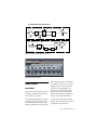
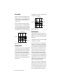
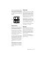
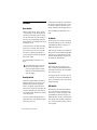
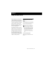
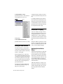
Aphex Aural Exciter Type III
Plug-In Guide
Version 2.0 for Macintosh and Windows
Digidesign
2001 Junipero Serra Boulevard
Daly City, CA 94014-3886 USA
tel: 650·731·6300
fax: 650·731·6399
Technical Support (USA)
tel: 650·731·6100
fax: 650·731·6384
Product Information (USA)
650·731·6102
800·333·2137
International Offices
Visit the Digidesign Web site
for contact information
Web Site
www.digidesign.com
Copyright
This guide is copyrighted ©2002 by Digidesign, a division of
Avid Technology, Inc. (hereafter “Digidesign”), with all rights
reserved. Under copyright laws, this guide may not be
duplicated in whole or in part without the written consent of
Digidesign.
DIGIDESIGN, AVID and PRO TOOLS are trademarks or
registered trademarks of Digidesign and/or Avid Technology,
Inc. All other trademarks are the property of their respective
owners.
All features and specifications subject to change without
notice.
PN 932910293-00 REV A 04/02
contents
Chapter 1. Introduction . . . . . . . . . . . . . . . . . . . . . . . . . . . . . . . . . . . . . . . . . . . . . . . . . . . . . . 1
System Requirements . . . . . . . . . . . . . . . . . . . . . . . . . . . . . . . . . . . . . . . . . . . . . . . . . . . . . 1
Installing Aural Exciter . . . . . . . . . . . . . . . . . . . . . . . . . . . . . . . . . . . . . . . . . . . . . . . . . . . . . 1
Working with Aural Exciter Plug-In . . . . . . . . . . . . . . . . . . . . . . . . . . . . . . . . . . . . . . . . . . . . 2
Conventions Used in This Guide . . . . . . . . . . . . . . . . . . . . . . . . . . . . . . . . . . . . . . . . . . . . . . 2
Chapter 2. Aural Exciter Controls . . . . . . . . . . . . . . . . . . . . . . . . . . . . . . . . . . . . . . . . . . . . . 3
Aphex Aural Exciter Type III Overview . . . . . . . . . . . . . . . . . . . . . . . . . . . . . . . . . . . . . . . . . . 3
Adjusting Parameters . . . . . . . . . . . . . . . . . . . . . . . . . . . . . . . . . . . . . . . . . . . . . . . . . . . . . 4
Meters . . . . . . . . . . . . . . . . . . . . . . . . . . . . . . . . . . . . . . . . . . . . . . . . . . . . . . . . . . . . . . . . 4
Rotary Controls . . . . . . . . . . . . . . . . . . . . . . . . . . . . . . . . . . . . . . . . . . . . . . . . . . . . . . . . . . 5
Switches . . . . . . . . . . . . . . . . . . . . . . . . . . . . . . . . . . . . . . . . . . . . . . . . . . . . . . . . . . . . . . 8
Chapter 3. Using the Aural Exciter . . . . . . . . . . . . . . . . . . . . . . . . . . . . . . . . . . . . . . . . . . . 11
Inserting Aural Exciter on a Track . . . . . . . . . . . . . . . . . . . . . . . . . . . . . . . . . . . . . . . . . . . . 11
Setting the Gain Structure . . . . . . . . . . . . . . . . . . . . . . . . . . . . . . . . . . . . . . . . . . . . . . . . . 12
Information on Clipping . . . . . . . . . . . . . . . . . . . . . . . . . . . . . . . . . . . . . . . . . . . . . . . . . . . 12
Using the Tune Fader . . . . . . . . . . . . . . . . . . . . . . . . . . . . . . . . . . . . . . . . . . . . . . . . . . . . . 13
Using the SPR Switch . . . . . . . . . . . . . . . . . . . . . . . . . . . . . . . . . . . . . . . . . . . . . . . . . . . . 13
Using Aural Exciter on 192 kHz or 176.4 kHz Stereo Tracks . . . . . . . . . . . . . . . . . . . . . . . . . 14
Index . . . . . . . . . . . . . . . . . . . . . . . . . . . . . . . . . . . . . . . . . . . . . . . . . . . . . . . . . . . . . . . . . . . . . 15
Contents
iii
iv
Aphex Aural Exciter Plug-In Guide
chapter 1
Introduction
Congratulations on your purchase of the Aphex
Aural Exciter® Type III plug-in for Pro Tools
TDM systems.
The Aphex Aural Exciter Plug-In Guide covers features and functions of the Aural Exciter, providing suggestions on how to use it in a Pro Tools
session. This guide is meant to be a supplement
to your Pro Tools TDM system guides.
The Aural Exciter plug-in is a real-time TDM
plug-in that retains the look and sound of
Aphex Systems’ renowned hardware units. Aural Exciter makes it possible to recreate and restore missing harmonics.
System Requirements
To use Aural Exciter you need:
A Digidesign-approved Pro Tools|HD system
with version 5.3 software or higher, or
Pro Tools|24 MIX system with version 5.0 software or higher.
For the latest compatibility information, contact your local Digidesign dealer or visit Digidesign’s Web site.
www.digidesign.com/compato
What’s New in Aural Exciter
Installing Aural Exciter
• Support for Aural Exciter on Pro Tools|HD systems on Macintosh and Windows.
Refer to the electronic PDF copy of the Aphex
Aural Exciter and Big Bottom Installation Guide for
information on installing your Aphex plug-ins.
• Support for Aural Exciter on Pro Tools|24 MIX
systems on Macintosh and Windows.
• Support for 192 kHz, 176.4 kHz, 96 kHz,
88.2 kHz, 48 kHz, and 44.1 kHz sessions.
On 192 kHz or 176.4 kHz stereo tracks,
Aural Exciter is only available as a multimono plug-in.
• Plug-in authorization using the iLok USB
hardware key from PACE Anti Piracy. (See the
Aphex Aural Exciter and Big Bottom Installation
Guide.)
Chapter 1: Introduction
1
Working with Aural Exciter
Plug-In
Conventions Used in This
Guide
Refer to the Pro Tools Reference Guide, the DigiRack Plug-Ins Guide, or the electronic PDF copy
of the Digidesign Plug-Ins Guide for information
on working with plug-ins, including:
All Digidesign guides use the following conventions to indicate menu choices and key commands:
• Plug-Ins as Inserts
• The Plug-In Window
:
Convention
Action
File > Save Session
Choose Save Session
from the File menu
Control+N
Hold down the Control
key and press the N key
Option-click
Hold down the Option key
and click the mouse button
• Editing Plug-In Parameters
• Automating Plug-Ins
• Using the Librarian
The following symbols are used to highlight important information:
User Tips are helpful hints for getting the
most from your Pro Tools system.
Important Notices include information that
could affect your Pro Tools session data or
the performance of your Pro Tools system.
Shortcuts show you useful keyboard or
mouse shortcuts.
Cross References point to related sections in
the Pro Tools Guides.
2
Aphex Aural Exciter Plug-In Guide
chapter 2
Aural Exciter Controls
Aphex Aural Exciter Type III
Overview
Aphex Systems, Inc. first introduced Aural Exciter in 1975. Since then, several refinements
and improvements have been incorporated into
its original design. The Aural Exciter plug-in is
modeled after the TYPE III Aural Exciter. Aural
Exciter has become a standard in the professional audio industry, and has been used on
many albums, CDs, movies, broadcast productions, commercials, and concerts. The Aural Exciter plug-in for Pro Tools TDM systems continues this tradition of success, and is ready for use
with the latest cutting edge music productions.
Harmonics are musically and dynamically related to the original sound, and reveal the fine
differences between voices and various instruments. Reproduced sound is audibly different
from the original live sound because of the loss
in harmonic detail, often sounding dull and lifeless.
The Aural Exciter is an audio process that recreates and restores missing harmonics. It actually
adds harmonics, restoring the sound’s natural
brightness, clarity and presence, effectively improving detail and intelligibility. Use Aural Exciter on specific instruments or in the final mix
to bring life back to recordings.
Unlike EQs and other brightness enhancers
which only boost the high frequencies that often alter the overall tonal balance, the Aural Exciter extends the high frequencies. The stereo
image is enhanced with the Aural Exciter. This
results in a greater perceived loudness without
an introduction of noise into the audio path,
commonly caused by increased gain.
The Aural Exciter is a single-ended process
which can be inserted at any point within the
audio chain (see Figure 1 on page 5). The input
signal is split into two paths. One path goes to
the output unmodified, while the other path,
known as a side-chain, goes through the Aural
Exciter, which is comprised of a tunable highpass filter and a harmonics generator. The Aural
Exciter applies frequency-dependent phase shift
and amplitude-dependent harmonics. The output of the Aural Exciter's harmonic generator is
mixed back with the unmodified signal, lower
in level.
When used at nominal settings, the Aural Exciter does not add significant average level to
the original signal. Even though the added information is low level, the perception is a dramatic increase in mid and high frequencies.
The Aural Exciter is patented in the United
States, Japan and most of Europe. Others may
claim they are doing the same thing, but they
can only resort to some form of EQ (amplitude
Chapter 2: Aural Exciter Controls
3
correction or expansion), phase scrambling
and/or filtering. They can only increase peak
levels causing clipping, feedback, tape distortion and listener fatigue.
Enabling Switches
To enable a switch, click on the switch.
Meters
Adjusting Parameters
Drive Meter
Editing Parameters Using a Mouse
You can adjust rotary controls with a mouse by
dragging horizontally or vertically. Parameter
values increase as you drag upward or to the
right, and decrease as you drag downward or to
the left.
Editing Parameters Using a Computer
Keyboard
Each rotary control has a corresponding parameter text field directly below it. This displays the
current value of the parameter. You can edit the
numeric value of a parameter with your computer keyboard.
To type a parameter value:
1 Click on the parameter text that you want to
edit.
2 Change the value.
• Type the desired value.
– or –
• To increase a value, press the Up Arrow on
your keyboard. To decrease a value, press
the Down Arrow on your keyboard.
3 Press Enter on the numeric keyboard to input
the value and remain in keyboard editing mode.
– or –
Press Return (Macintosh) or Enter on the alpha
keyboard (Windows) to enter the value and
leave keyboard editing mode.
4
Aphex Aural Exciter Plug-In Guide
The Drive meter monitors the peak level to the
harmonic generator. It works in conjunction
with the Drive switch. A red LED at the top of
the meter indicates if there is clipping.
For optimal performance keep the peak hold
meter of the Drive meter inside the yellow area.
The harder you drive the Exciter, the more Exciter enhancement you generate. If you cannot
get the Drive meter to register in the yellow area,
try setting the Drive switch to High (Drive
switch enabled).
Out Meter
The Out meter lets you monitor the output level
after Aural Exciter processing. A red light at the
top of the meter indicates if there is clipping.
If your input material has a peak level, be
careful to prevent clipping when setting the
Mix control.
BLOCK DIAGRAM OF AURAL EXCITER TYPE III
Bypass (closed)
Solo
INPUT
Attenuation
Level (–∞, 0 dB)
Summing
Spectral Phrase
Refracter
OUTPUT
Bypass (open)
SPR (On/Off)
Aural Exciter
MAIN AUDIO PATH
Drive (+6 dB / +18 dB)
Dynamic
Compressor
Programmed
Gain Buffer
Attenuation
State Variable
Filter
Harmonics
Generator
Tune
Waveform
Generator
Mix
(+6 dB, –∞ / +18 dB, –∞)
Peaking Null FIll
AURAL EXCITER SIDE-CHAIN
Harmonics
Density
Timbre
Figure 1. Block Diagram of Aphex Aural Exciter, Type III
Figure 2. Aphex Aural Exciter, Type III
Rotary Controls
Level Control
The Level control sets the attenuation of the input signal. For normal operation set the Level
control on Max (no attenuation).
The Aural Exciter TDM plug-in has an internal
gain structure that boosts +6 dB of the output
from the high-pass filter into the side-chain.
The Drive switch further boosts the signal level
fed into the harmonics generator. When Drive is
set to Normal, you obtain a boost of +6 dB; in
the High position you can get an additional
6 dB of gain, for a total maximum boost of
+18 dB. You can also generate a boost in the
high-pass filter section by setting Peaking to
Max. If the Drive signal runs into clipping, use
the Level control to adjust the Drive level.
If you run into headroom problems when adjusting the Mix control, adjust the Level control
to generate the necessary headroom.
Chapter 2: Aural Exciter Controls
5
Underneath the control, the amount of Peaking
is displayed as a percentage.
Tune Control
The Tune control sets the bandwidth (corner
frequency) of the second order high-pass filter
in the side-chain prior to the harmonics generator. The range of the control extends from
700 Hz to 7 kHz.
TYPE III PEAKING RESPONSE
10.0
PEAKING at MAX
6.0
2.0
PEAKING
at MIDPOINT
-2.0
PEAKING at MIN
RESPONSE (dB)
Figure 3 demonstrates the range of the Tune
control from 700 Hz to 7 kHz with Null Fill set
near Min and Peaking set at the mid-point position. As you read the following sections on Peaking and Null Fill, notice the interaction these
controls have on Tune, as well as on each other.
-6.0
NULL FILL at MIN
TUNE at midpoint
for all curves
20.0
100.0
1000.0
10000.0
FREQUENCY (Hz)
Figure 4. Peaking control
Null Fill Control
TYPE III TUNING RANGE
7.0
5.0
TUNE at 700 Hz
3.0
RESPONSE (dB)
TUNE at 3 kHz
(midpoint)
1.0
TUNE at 7 kHz
-1.0
NULL FILL at Minimum
PEAKING at midpoint
for all curves
20.0
100.0
1000.0
The Null Fill control adjusts the curve of the
high-pass filter to “fill in” the null caused by the
summing of the side-chain return signal and the
input signal.
Underneath the control, the amount of Null Fill
is displayed as a percentage.
10000.0
FREQUENCY (Hz)
Figure 3. Tune control
Peaking Control
The Peaking control provides a damping effect
on the leading frequency edge of the high-pass
filter controlled by Tune. As you vary this control from Min to Max, the Tune frequency becomes more accentuated, as demonstrated in
Figure 4. However, at the same time, a dip is created just before the accentuated Tune frequency. This dip or null becomes larger as Peaking is increased.
This control compensates for “phase pulling,”
which occurs as a side effect of the time delay
present in the side-chain signal, an important
part of the Aural Exciter operating theory. As the
time delay “stretches” transient waveforms to
create a perception of louder sound, a “dip” or
“null” also occurs in the output equalization
curve at the Tune frequency. As a result, the
“null” frequencies are de-emphasized, thus giving even more emphasis to the higher frequencies. Although this often is a desirable effect, the
Null Fill control was created to allow the user to
fill-in the null by a selectable amount for any
applications requiring less emphasis.
Figure 5 shows three different Null Fill settings
with Tune set at the mid-point position. With
the Null Fill control set at Min, there is a noticeable drop in the frequency response, just before
the start of the high-pass shelf boost. At this setting, program material under enhancement
6
Aphex Aural Exciter Plug-In Guide
would lose some presence. When the Null Fill
control is set at Max, the frequency dip is filled,
but the frequencies associated with the shelf top
become accentuated. Also notice the shift in the
Tune frequency (0 dB axis) for the range of Null
Fill settings.
TYPE III NULL FILLRANGE
7.0
NULL FILL at MAX
Timbre Control
The Timbre control sets the order or type of harmonic signal being generated by way of the Harmonics control. The control can be varied from
all Even harmonics in the Min position, to all
Odd harmonics at the Max position. Odd order
harmonics will sound softer to your ear, while
even harmonics will sound harsher.
5.0
3.0
NULL FILL at
Midpoint
RESPONSE (dB)
1.0
NULL FILL at MIN
-1.0
PEAKING at midpoint
for all curves
20.0
100.0
1000.0
Varying the Timbre control between the two extremes will provide you with a mix of both Even
and Odd harmonics in proportion to the control
position. To emphasize the effect of the Timbre
control, set the Density switch to High.
10000.0
FREQUENCY (Hz)
Figure 5. Null Fill control
The display underneath the controls reads from
+100% (all Odd) to –100% (all Even).
Harmonics Control
Mix Control
The Harmonics control adjusts the amount of
harmonics being generated, which is displayed
as a percentage underneath the controls.
The harmonic generator produces harmonic
components according to a complex set of laws,
including considerations for transient and
steady-state qualities, as well as relative amplitude of the original audio signal.
As you move the control up, harmonic content
increases proportionally as it works in conjunction with the Timbre control. Moreover, the
amount of harmonics generated is dependent
on the input level. The gain of the harmonics
automatically increases as the input level increases.
The Mix control determines the amount of Aural Exciter enhancement mixed into the original
signal. The control ranges from Min (no enhancement), up to Max, representing approximately a 6 dB boost when the Drive switch is set
to Normal, and approximately an 18 dB boost
when it is set to High.
Underneath the controls, the amount of enhancement mixed into the original signal is displayed as a percentage.
The generated harmonics are not products of
harmonic distortion, since they are intelligently
produced and formed into a power envelope
that enhances rather than distorts the final audio signal.
Chapter 2: Aural Exciter Controls
7
Switches
Drive Switch
The Drive switch offers two settings, Normal
(+6 dB) and High (+18 dB). This sets the input
sensitivity to the harmonics generator. In general, this switch will be left in the Normal position. However, weak signals may require more
gain, in which case you should place this switch
in the High position.
Use the Drive meter to determine if the signal
gain needs to be increased. When the meter
level stays in the green area (never rising into
the yellow area), then the input signal is too
low. Raise the input sensitivity by toggling the
Drive switch to High.
The switch illuminates when Drive is set to
High.
If your input signal is in the yellow area of
the Drive meter, this indicates you are receiving an acceptable signal level. Switching the Drive switch to High in this instance
could cause clipping.
Density Switch
The Density switch determines the amount of
harmonics generated by choosing one of two
different harmonics generator algorithms.
When set on High, the output from the harmonic generator expands low level signals and
compresses the highest peaks. This setting provides a higher density of harmonics with better
control of peak levels.
If you have problems with clipping when setting the Mix control, switch Density to High for
better peak level control.
8
Aphex Aural Exciter Plug-In Guide
Since the amount of harmonics is dependent on
the input level, start with the switch set to Normal. Switch to High if you still want a greater
density of harmonics after the input level is set.
The switch illuminates when Density is set to
High.
Ax Switch
The Ax switch gives you the choice of turning
the Aural Excitement process On or Off. The Ax
switch illuminates when Ax is engaged, confirming that the effect is On.
Unlike the Bypass switch, the audio signal from
the input does travel through the DSP algorithm
on the way to the output whenever Ax is Off.
This means that the SPR effect can still be active,
by switching Ax Off and SPR On.
Solo Switch
When engaged, the Solo switch gives you a
choice of auditioning the Aural Excitement signal without the main audio, The switch illuminates when Solo is active.
As an application for the Solo switch, select Solo
to return the pure effect back to the mixing console for precise memory control of the Aural Excitement signal only.
SPR Switch
The SPR switch controls the Spectral Phase Refractor effect. This effect is independent of all
other controls or switches, except Bypass. The
switch illuminates when SPR is engaged, confirming that SPR is On. SPR processes the main
audio signal in such a way that bass frequencies
(up to 150 Hz) lead phase in relation to the rest
of the spectrum.
Through the many steps of recording, duplicating, distributing, and reproducing sound, the
phase of the low frequency audio spectrum becomes delayed compared to mid and high frequencies. SPR corrects the bass delay anomaly to
restore clarity and openness and significantly
increases the apparent bass energy level without
adding any amplitude equalization or bass
boost.
To audition the effect of SPR on the audio signal, turn the Ax switch Off and turn SPR On.
Then alternately turn the Bypass switch On and
Off to hear the SPR effect on incoming audio.
The SPR function is depicted in Figure 6, which
shows the frequency dependent time delay that
is produced. Note that this is not the same as a
group delay. Group delay is a constant time delay at all frequencies.
The Link switch is for stereo operation only. It
links the left and right controls so they work as
one. Grab the control on one page with the cursor and move it to the required position. The
control on the other page automatically updates. In this way both controls can be set to the
exact same position. Stereo controls may be
linked temporarily by holding down the Shift
key while adjusting the control.
The switch illuminates when Link is activated.
LR (Left/Right) Switches
The LR switch is for stereo operation only. It allows you to view or change parameters on one
channel at a time.
The switch for the currently displayed channel
illuminates. Choosing the unlit switch, changes
the display to the other channel.
SPECTRAL PHASE REFRACTOR
PSYCHOACOUSTIC PHASE
400
Link Switch
12
350
10
PHASE (Degrees)
LEADING PSYCHOACOUSTIC PHASE RESPONSE
250
8
200
6
150
ACTUAL TIME DELAY
100
4
50
TIME DELAY (Milliseconds)
300
To edit both channels simultaneously, click on
the Link switch.
2
0
-50
0
10
100
1000
10000
AUDIO FREQUENCY (Hz)
Figure 6. SPR switch
Bypass Switch
The Bypass switch allows the main audio signal
to bypass the Aural Exciter plug-in completely.
The indicator switch illuminates when Bypass is
engaged.
The Bypass switch on the plug-in provides the
same function as the Bypass command on the
Pro Tools Plug-Ins window, on a per-channel
basis.
Chapter 2: Aural Exciter Controls
9
10
Aphex Aural Exciter Plug-In Guide
chapter 3
Using the Aural Exciter
In the recording studio, post production suite,
or similar environment, post-processing of previously recorded audio tracks with the Aural Exciter can restore lost vibrance and realism, even
to the extent of saving dialogue or sound effects
which were thought to be unusable. Instruments and vocals can be made to stand out in
the mix without substantially increasing the
mix levels or using equalization.
The TDM mixing environment is very flexible
offering several ways to route and use the Aural
Exciter in a session. This section provides some
suggestions for efficient use of the Aural Exciter
in your TDM setups. Since the exact steps you
take to use the Aural Exciter’s TDM capabilities
will differ depending on the nature of your session and your specific Pro Tools mixer setup, the
examples are somewhat generalized.
Inserting Aural Exciter on a
Track
To use Aural Exciter in a Pro Tools session, insert
it on a track. Before doing so, make sure the Inserts View is shown in the Mix window.
Although Aural Exciter is typically used as
an insert on a track (in the same manner
compressors and equalizers are used), it can
also be used in a send and return arrangement. Refer to the Pro Tools Reference Guide,
the DigiRack Plug-Ins Guide, or the electronic PDF copy of the Digidesign Plug-Ins
Guide.
To show inserts in the Mix window:
■ Choose Display > Mix Window Shows > Inserts View.
Chapter 3: Using the Aural Exciter
11
To insert Aural Exciter on a track:
Click the Insert Selector on the track and select the plug-in that you want to use.
■
click here
Using the Level fader to adjust for more headroom is also useful when restoring older recordings.
For optimal performance keep the peak hold
meter of the Drive meter inside the yellow area.
The harder you drive the Exciter, the more Exciter enhancement you generate. If you cannot
get the Drive meter to register in the yellow area,
try setting the Drive switch to High.
Information on Clipping
Inserting a plug-in
To remove Aural Exciter from a track:
■
Click the Insert Selector and choose No Insert.
Setting the Gain Structure
If the input material has a very high peak-topeak level and no additional headroom for Exciter effects, use the Level fader to adjust the signal level to avoid clipping.
When using digital audio as a sound source,
such as a CD Player with S/PDIF outputs, there is
a very high peak-to-peak level because the material on the CD is optimized for the best signalto-noise performance. In this situation the Level
fader can be used to adjust the signal level to
gain additional headroom.
In an analog based system you will have the
same headroom problem when using a very
high peak-to-peak level signal.
12
Aphex Aural Exciter Plug-In Guide
Your ears are usually a better judge of when a
signal is clipping than the VU meter. Non-periodic clipped transients have to be driven extremely hard for it to be heard as clipping. Do
not assume that if your drive signal is “too high”
the Drive meter indicates brief moments of clipping.
The Exciter’s harmonics generator has a “masking effect” on a clipped drive signal. You would
have to drive the harmonic generator very hard
before you would actually hear clipping.
Optimizing the Aural Exciter
Effects
When using the Aural Exciter, the output signal
level has to be equal to the input signal level
plus the enhanced Exciter effect. The dynamic
characteristics of the harmonic generator used
in the Aural Exciter plug-in are based on a complex algorithm that includes the signal peak
level, the averaged steady state level, and the dynamic characteristics.
Unlike an EQ, which adds a constant boost in
the high end, the Aural Exciter enhancement is
added into the input signal is such a way that
the average signal level will be virtually unchanged.
The Level, Tune, Peaking, Null Fill, Harmonics,
Timbre and Mix faders provide separate left and
right faders when in stereo. For stereo, a separate
set of switches for independent control of the
left and right channels is provided for Ax, Solo,
SPR, Bypass, Drive and Density.
The Tune fader adjusts the corner frequency of
the high pass filter and the Mix fader varies the
amount of Aural Exciter enhancement that is
mixed with the unmodified signal.
Experiment with the Aural Exciter faders and
switches to hear how each one enhances the
original audio signal.
To experiment with Aural Exciter:
1 Set the Level fader on Max.
2 Set the Drive switch to reflect the current
nominal level.
3 Make sure the Bypass switch is deactivated
(Bypass light off).
4 Make sure the Ax switch is activated (Ax light
on).
5 Set Density to Normal. (Density light off). As
you make the following adjustments, alternate
the Density switch between Normal and High to
hear the change in the Aural Exciter effect.
6 Put the Aural Exciter Mix fader on Max, mak-
ing it easier to hear the effect as it changes.
Using the Tune Fader
After a while you’ll get a sense of where you like
your Tune setting when using the Aural Exciter
on individual tracks. It’s best not to process the
same range of frequencies with the Tune fader
during the final mix. If you already processed individual tracks with Aural Exciter, try starting
the final mix with the Tune fader in the maximum position which is approximately 7 kHz.
You should get a spacious, three-dimensional
mix with an open “airy” quality.
Using the SPR Switch
The SPR function can produce a useful effect
with solo voices (human and instrumental) or
mixed programs (such as drama and music).
There is no specific time when SPR should or
shouldn’t be used. Experiment with it on various types of material until you get used to the effect. Listen carefully as you operate the SPR
switch. The effect may be noticed only at certain
times (such as specific modulations of a voice or
during a particular instrumental playing style or
passage). Don't expect to hear the sound change
radically. The SPR is usually subtle, adding a certain beauty and good feeling to the sound. In
time you will find that the SPR does indeed produce demonstrable results. For instance, the SPR
effect can:
7 Vary the Tune fader and listen for the frequency range that is being enhanced. The Tune
fader can be used to enhance a particular instrument so it stands out in the mix.
• Drop pitch of ultra low bass
8 Adjust the Harmonics fader and listen for the
change in harmonics being added to the original audio signal.
• Improve definition of high frequency
sounds (such as on cymbals and bells)
9 When finished experimenting, set the Mix
• Increase depth and clarity of male voices
• Increase apparent bass power
• Unmask instruments or sonic details hidden in the mix
• Improve speech articulation and presence
control to taste. Keep in mind that a little Aural
Exciter goes a long way.
Chapter 3: Using the Aural Exciter
13
Successful use of the SPR depends on the character of the original sound. It is hard to predict in
advance what will be the effect of the SPR. Typically, you may find it useful about 50% of the
time. At other times, there will be little or no discernible effect. Seldom does the effect damage
good audio, so it could be left on as a matter of
course. A few examples of audio material likely
to be helped by the SPR are:
• Highly overdubbed tape tracks
• Live acoustic recordings
• Electronic keyboards
• Productions composed from tape cartridge
and cassette sources
• Material recorded with transformer coupled mic preamps
• Vocals recorded with dynamic microphones
• Reverberant live sound or recordings
• Highly equalized material
• Delayed, flanged, or digitally processed material
• Material from broadcast audio reception
(such as store casting and muzak)
14
Aphex Aural Exciter Plug-In Guide
Using Aural Exciter on
192 kHz or 176.4 kHz Stereo
Tracks
On 192 kHz or 176.4 kHz stereo tracks, Aural Exciter is only available as a multi-mono plug-in.
Parameters for all channels are linked by default
so that you can adjust them in tandem. You can
unlink parameter controls for independent adjustment using the Master Link button.
Refer to the Pro Tools Reference Guide, the DigiRack Plug-Ins Guide, or the electronic PDF copy
of the Digidesign Plug-Ins Guide for information
on working with multi-mono plug-ins.
index
A
M
adjusting parameters 4
Ax switch 8
meters 4
Mix control 7
B
N
block diagram 5
Bypass switch 9
Null Fill control 6
O
C
clipping 12
optimizing Aural Exciter 12
Out meter 4
D
P
Density switch 8
Drive meter 4
Drive switch 8
parameters 4
Peaking control 6
R
G
gain structure 12
guide conventions 2
removing Aural Exciter 12
rotary controls 5
S
H
Harmonics control 7
Solo switch 8
SPR switch 8, 13
switches 8
I
inserting Aural Exciter 11
installation 1
introduction 1
T
Timbre control 7
Tune control 6
Tune fader 13
L
Level control 5
Link switch 9
LR (Left/Right) switches 9
U
using Aural Exciter 11
W
what’s new 1
Index
15