1
CBM-253 User’s Manual
Declaration of Conformity
Manufacturer’s Name :
Japan CBM Corporation
Manufacturer’s Address:
CBM Bldg., 5-68-10, Nakano, Nakano-ku
Tokyo, 164-0001, Japan
Declare the Product
Product Name:
Model Number(s):
Thermal Label Printer
CBM-253 Series
(CBM-253P, CBM-253R)
(S.No.60400000 ~ )
Conform to the following Standards:
LVD:
EMC:
EN60950
EN55022
EN61000-3-2
EN61000-3-3
EN50082-1
IEC801-2
IEC801-3
IEC801-4
: 1992+A1+A2:1993
: 1994 Class B
: 1995
: 1995
: 1992
: 1991 4KV CD, 8KV AD
: 1984 3V/m, 26MHz-1GHz, AM1KHz 80%
: 1988 0.5KV Signal Line 1KV AC mains
Supplementary Information
“The product complies with the requirements of the Low Voltage Directive 73/23/EEC, 93/68/EEC and
the EMC Directive 89/336/EEC, 91/263/EEC, 92/31/EEC, 93/68EEC”
Place
Tokyo, Japan
Date
April.1996
Signature:
Full Name :
Position :
Mikio Moriya
General Manager
R & D Department
Europe Contact :
Norco Declaration AB
Box 7146 S-250 07 Helsingborg, Sweden
Warning
This is a Class A products. In a domestic environment this product may cause radio interference in which case the user
may be required to take adequate measures.
This declaration is applied only for 230V model.
CITIZEN
CBM-253 User’s Manual
IMPORTANT SAFETY INSTRUCTIONS
•
Read all of these instructions and save them for fu ture reference.
•
Follow all warnings and instructions marked on the product.
•
•
Unplug this product from the wall outlet before cleaning. Do not use liquid or aerosol cleaners.
Use a damp cloth for cleaning.
Do not use this product near water.
•
Do not place this product on an unstable cart, stand or table. The product may fall, causing
serious damage to the product.
•
•
•
•
•
•
•
•
Slots and openings on the back or bottom of the case are provided for ventilation. To ensure
reliable operation of the product and to protect it from overheating, do not block or cover these
openings. The openings should never be blocked by placing the product on a bed, sofa, rug of
other similar surface. This product should never be placed near or over a radiator or heater. This
product should not be placed in an built-in installation unless proper ventilation is provided.
This product should be operated from the type of power source indicated on the marking label. If
you re not sure of the type of power available, consult your dealer or local power company.
Do not allow anything to rest on the power cord. Do not place this product where the cord will be
walked on.
If an extension cord is used with this product, make sure that the total of the ampere ratings of the
products plugged into the extension cord does not exceed the extension cord ampere rating. Also,
make sure that the total of all products plugged into the wall outlet does not exceed 15 amperes.
Never push objects of any kind into this product through cabinet slots as they may touch
dangerous voltage points or short out parts that could result in a risk of fire or electric shock.
Never spill liquid of any kind on the product.
Except as explained elsewhere in this manual, do not attempt to service this product by yourself.
Opening and removing the covers that are marked “Do Not Remove” may expose you to
dangerous voltage points or other risks. Refer all servicing on those compartments to service
personnel.
Unplug this product from the wall outlet and refer servicing to qualified service personnel under the
following conditions:
A. When the power cord or plug is damaged or frayed.
B. If liquid has been spilled into the product.
C. If the product has been exposed to rain or water.
D. If the product does not operate normally when the o perating instructions are followed. Adjust
only those controls that are covered be the operating instructions since improper adjustment of
other controls may result in damage and will often require extensive work by a qualified
technician to restore the product to normal operation.
E. If the product has been dropped or the cabinet has been damaged.
F. If the product exhibits a distinct change in performance, indicating a need for service.
Please keep the poly bag which this equipment is packed in away from children or throw it away to
prevent children from putting it on. Putting it on may cause suffocation.
CITIZEN
CBM-253 User’s Manual
IMPORTANT: This equipment generates, uses, and can radiate radio frequency energy and if not
installed and used in accordance with the instruction manual, may cause interference to radio
communications. It has been tested and found to comply with the limits for a Class A computing
device pursuant to Subpart J of Part 15 off FCC Rules, which are designed to provide reasonable
protection against such interference when operated in a commercial environment. Operation of this
equipment in a residential area is likely to cause interference, in which case the user at his own
expense will be required to take whatever measures may be necessary to correct the interference.
CAUTION: Use shielded cable for this equipment.
Sicherheitshinweis
Die Steckdose zum Anschluß dieses Druckers muß nahe dem Grät angebracht und leicht zugänglich
sein.
For Uses in Canada
This digital apparatus does not exceed the class A limits for radio noise emissions from digital,
apparatus, as set out in the radio interference regulations of the Canadian department of
communications.
Pour L’utilisateurs Canadiens
Cet appareil numerique ne depasse pas les limites de caregorie a pour les emissions de bruit radio
emanant d’appareils numeriques, tel que prévu dans les reglements sur l’interference radio du
department Canadien des communications.
CITIZEN
CBM-253 User’s Manual
<Cautions>
1.
2.
3.
4.
5.
6.
7.
8.
9.
Before using the equipment, be sure to read this User's manual thoroughly .
Portions of the contents of this User's manual may be changed without prior notice.
The reproduction of part or all of the contents of this User's manual without permission is strictly
forbidden.
Absolutely do not carry out maintenance, disassembly, or repair of parts that are not specified in
this User's manual.
Note that losses which may be attributed to the customer's wrong operation method or usage
environment will be outside the responsibility of this company.
Do not carry out operations other than those explained in this User's manual, since doing so may
become a cause of accidents or breakdowns.
Because data is basically transient, long-period and permanent storage of data will not be possible.
Please note in advance that this company will not be responsible in any way for losses or lost
profits caused through the clearing of data due to breakdowns, repairs, investigations, etc.
If any questionable points, mistakes, omitted explanations, etc. are found in the contents of this
document, please notify this company.
Please note that notwithstanding the conditions in above 8, this company will not be responsible
for the consequences of results obtained through operation of this equipment.
CITIZEN
CBM-253 User’s Manual
CAUTIONS FOR SAFE USE
(Be sure to follow these cautions)
The cautions that must be followed in order to prevent injury to persons using this equipment
or to other persons, and to protect against damage to property are displayed as shown below.
• The danger of injury or damage resulting from mistaken methods of use and not following
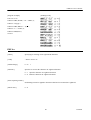
the displayed cautions will be explained as follows:
The WARNING symbol indicates that if the methods of
WARNING!
use is mistaken by not following the explanation given,
there will be a possibility of the occurrence of death or
serious injury.
The CAUTION symbol indicates that if the methods of
use is mistaken by not following the explanation given,
CAUTION
there will be a possibility of the occurrence of problems
or physical damage.
The symbol represents an illustration shown to attract reader’s attentions.
WARNING!
• Do not subject this equipment to excessive force or shocks such as by treading on it, dropping it or
hitting it, since these actions may result in damage causing a danger of fire or electrical shock.
In a situation where the equipment has been damaged, switch off the power, remove the power plug
from the mains outlet, and contact your sales shop.
• Do not install this equipment in unstable locations that are not flat, since there will be a danger of the
equipment falling down or falling over, causing injury.
CITIZEN
CBM-253 User’s Manual
WARNING !
• Do not install this equipment in locations with poor ventilation, and do not use the equipment in such
a way that the ventilation port is obstructed, since these actions may result in fire or electric shock.
• Do not use this equipment in locations such as laboratories in which chemical reactions take place,
or in locations in which the air includes salt or toxic gases, since these actions may result in fire or
electric shock.
• Do not use this equipment at voltages other than the specified voltage or at frequencies other than at
the specified frequencies, since the use other voltages and frequencies may result in breakdowns,
creating a danger of fire or electric shock.
In the situation where a breakdown has taken place, switch off the power, remove the power plug
from the mains outlet, and contact your sales shop.
• Do not insert or remove the power cables or data cables by pulling on the cables, and do not pull on
or carry the main unit in such a way as to subject the cables to force, since these actions will produce
the risk of overheating or smoking, creating a source of fire or electric shock.
• Do not drop or insert foreign objects like paper clips or split pins, etc. into the equipment, since these
actions may cause breakdowns, creating a danger of fire or electric shock.
In the situation where a breakdown has taken place. switch off the power, remove the power plug
from the mains outlet. and contact your sales shop.
• Do not arrange the power cable so that many plugs are using the same power outlet, since this action
will produce a risk of overheating or smoking, creating a source of fire or electric shock.
CITIZEN
CBM-253 User’s Manual
WARNING !
• Do not spill drinks such as tea, coffee or juice, or spray anti-mosquito preparations, etc. onto the
equipment, since these actions will result in breakdowns, fire or electric shock.
If water, etc. has been spilled into the equipment, switch off the power, remove the power plug from
the mains outlet, and contact your sales shop.
• Do not attempt to disassemble or modify this equipment, since these actions will cause fire or
electric shock.
• The plastic bag that contained the equipment should be stored in a location that is out of the reach of
children or should be destroyed, since there is a danger that children may suffocate themselves if
they place the bag over their heads.
• Do not attempt to attach anything other than a solenoid, or to attach a solenoid having a resistance
value or less than 24Ω to the drawer drive terminal.
The attachment of unspecified equipment may cause breakdown of the equipment or heat damage to
the solenoid, resulting in the danger of fire or electric shock.
• Do not carry out setting of the dip switches while the power plug is still plugged in to the power
outlet, since this action may cause breakdowns or the danger of electric shock.
• Do not remove any screws other than the screws that fix the rear cover, since removing other screws
may cause breakdowns or the danger of electric shock.
CITIZEN
CBM-253 User’s Manual
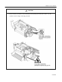
CAUTION
• Do not touch the print head or motor immediately after printing, since these parts will be very hot
and there will be a danger of burning your hand.
CITIZEN
CBM-253 User’s Manual
CAUTION
• Do not place objects on top of this equipment. since there will be a danger of the objects falling off
or falling over, resulting in injury.
• Do not use or store this equipment in locations that have fire or moisture, in locations that are
subject to direct sunlight, in locations that are abnormally hot such as close to heating equipment,
or in locations that are very humid or dusty, since t his will be a cause of breakdowns.
CITIZEN
CBM-253 User’s Manual
CONTENTS
1.
2.
OUTLINE...................................................................................................................................................1
1. 1
Features .............................................................................................................................................1
1. 2
Cautions for installation ....................................................................................................................1
1.3
General cautions................................................................................................................................2
BASIC SPECIFICATIONS ......................................................................................................................4
2.1
Model classifications.........................................................................................................................4
2.2
Printing specifications .......................................................................................................................4
2.3
Character specifications ....................................................................................................................5
2. 4
Paper specifications...........................................................................................................................8
2. 5
Interfaces.........................................................................................................................................10
2. 6
Data buffer ......................................................................................................................................10
2. 7
Paper and sensor..............................................................................................................................10
2. 8
Auto-cutter ......................................................................................................................................10
2. 9
Drawer kick-out connector..............................................................................................................10
2. 10 Electrical specifications .................................................................................................................10
2.11 External appearance specifications .................................................................................................11
2.12 Environmental specifications ..........................................................................................................11
2.13 Reliability specifications .................................................................................................................11
2.14 EMI standards and safety standards ................................................................................................11
3.
4.
EXTERNAL APPEARANCE AND NAMES OF EACH PART .........................................................12
3.1
External appearance and part names ...............................................................................................12
3.2
Explanation of each part .................................................................................................................13
OPERATION ...........................................................................................................................................15
4.1
Opening the printer cover ...............................................................................................................15
4.2
Opening the auto-cutter...................................................................................................................16
4.3
Setting the paper roll in the paper holder ........................................................................................17
4.4
Loading the paper............................................................................................................................18
4.5
Loading the paper when paper roll is small ....................................................................................19
4. 6
Setting the printer cover back .........................................................................................................22
4. 7
Opening the print head ....................................................................................................................23
4. 8
Serf-printing....................................................................................................................................24
4. 9
Hexadecimal dumping function ......................................................................................................24
4.10 Paper end detecting function ...........................................................................................................25
CITIZEN
CBM-253 User’s Manual
5.
INTERFACE SPECIFICATIONS .........................................................................................................26
5.1
Serial interface ................................................................................................................................26
5.2
Parallel interface .............................................................................................................................28
6.
DRAWER KICK-OUT CONNECTOR.................................................................................................30
7.
DIP SWITCH SETTlNGS.......................................................................................................................32
8.
FUNTIONS...............................................................................................................................................35
8.1
Command table ...............................................................................................................................35
8.2
Details of commands.......................................................................................................................37
8.3
9.
8.2.1
How to read each section ...................................................................................................37
8.2.2
Detailed explanations.........................................................................................................38
Character code tables ....................................................................................................................106
8.3.1
Page 0 (International character set: When U.S.A characters have been selected) ...........106
8.3.2
Page 1 (International character set: When U.S.A characters have been selected) ...........107
8.3.3
International character sets ..............................................................................................108
EXTERNAL DIMENSION...................................................................................................................109
CITIZEN
CBM-253 User’s Manual
1.
OUTLINE
This printer is a thermal line printer that is capable of being widely used with various types of data
communication terminals, POS terminals. or kitchen printers, etc. Because this printer uses a thermal line printings
systems, high speed printing is possible Furthermore, this printer may be widely utilized for various applications due
to the incorporation of ample functions.
1. 1 Features
•
Small size and light weight.
•
High speed printing. (400 dot lines/second)
•
Quiet operation and high reliability.
•
Due to the head opening mechanism, maintenance such as head cleaning will be simple.
•
RS-232C or Centronics interface are selectable.
•
Bar code printing is available. (Using exclusive commands)
•
The character size can be specified. (Standard size, double wide, double height, double wide and double
height.)
•
International character sets for 11 countries are built in.
•
A drawer kick-out interface is built in.
•
An auto-cutter is equipped.
•
The receiving buffer size is selectable. (45 bytes or 4 K bytes.)
1. 2 Cautions for installation
1. Concerning the use of this equipment, please carefully read the "Cautions for safe use", and carry out
operations following these cautions.
2. Confirm that the accessories listed below are included in addition to the printer main unit in this set of
equipment.
• Roll of paper.............................1 roll
• User's manual ...........................1 manual
3. This equipment should not be operated or stored in locations that have fire or moisture, in locations that are
exposed to direct sunlight, in locations that have abnormally high temperatures due to heating equipment or
hot equipment, in low locations, or in locations that are very damp or dusty.
4. This equipment should not be installed in locations where chemical reactions are generated, such as in
laboratories, etc.
1
CITIZEN
CBM-253 User’s Manual
5. This equipment should not be installed in locations where the air contains salt or toxic gases.
6. Install the printer on a flat, stable table top in a location having good ventila-tion. (Ensure that the ventilation
holes are not blocked.)
7. Items should not be placed on top of this equipment.
8. Note that the use of this equipment close to a radio or television receiver, or sharing the same power source
outlet may cause reception problems in the radio or television.
9. Only use this equipment at the specified voltage and frequency.
10. Do not place objects on top of the power cable or tread on top of the cable.
11. Do not pull or carry the main unit by holding the powe r cable or data cable.
12. Avoid connecting the power cable together with several other power cables to one power source outlet.
13. When pulling out the power cord, be sure to hold the plug while pulling it out.
14. Be sure to connect the connector properly. In particular, the internal terminals may be destroyed if the
connector is connected using the reverse polarity.
15. Be sure to set the power switch to OFF before mounting or removing the inter -face connector cable.
16. As far as possible, avoid over-lengthening the signal wire or connecting the printer to equipment that
generates noise. In situations where wiring of this kind must be carried out, apply adequate countermeasures
such as using shielded wiring or twisted pair wiring for each signal.
17. Only connect the prescribed solenoid to the drawer kick connector.
18. Ensure that there is a power source outlet close to the equipment, and make sure that this power source outlet
can be easily reached.
1.3
General cautions
1. Concerning the use of this equipment, please read the "Cautions for safe use", and carry out operations
following these cautions.
2. Do not carry out blank printing in the condition where there is no recording paper in the printing unit.
3. Take care not to touch the printing unit of the thermal print head with your bare hands.
4. When cleaning the head or platen, please use the exclusive cleaning kit for radio cassette recorder on the
market etc.
5. When cleaning the surface of the main unit case, do not use thinners, truculence, benzene or ketene group
solvents, or chemical-impregnated cleaning cloths.
6. Avoid using this equipment in locations which are subject to large amounts of oil, iron powder, debris, dust,
etc.
7. Take care not to drop paper clips, valve core pins, foreign objects, etc. into the main unit, since this will
become a cause of breakdowns.
2
CITIZEN
CBM-253 User’s Manual
8. Do not spill liquids or spray chemicals, etc. onto this equipment.
9. Do not subject this equipment to strong shock or vibration by standing on it. dropping it, hitting it, etc.
10. Carry out the operation of the operating panel unit with care, since disordered operation will become a cause
of breakdowns and mistaken operation. Furthermore, absolutely do not operate the panel using sharp objects
such as the tip of a pen etc.
11. During operation, do not touch moving parts such as gears, or the electrical parts inside the main unit.
12. Take care not to injure yourself or cause damage to other objects from the edges of the sheet metal.
13. If an abnormality occurs during use, immediately stop using the printer and remove the power cable from
the power source outlet.
14. If a breakdown occurs, do not attempt to disassemble the equipment. Be sure to leave the repair of this
equipment to Service personnel.
3
CITIZEN
CBM-253 User’s Manual
2.
BASIC SPECIFICATIONS
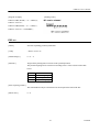
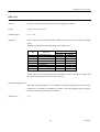
2.1
Model classifications
CBM - 253 - ∗ ∗ ∗ ∗
D: Drawer kick connecter is equipped
None: Not equipped
Power source voltage
120: AC 120V, 230: AC 230V
Character set
F: International characters
interface
R: Serial, P: Parallel
2.2
Printing specifications
Printing method
Direct heat coloring system (Direct thermal)
Printing direction
Line feeding by friction feeding
Effective printing area
Effective Printing width:
56mm 448 dots/line (Thermal paper)
53mm 424 dots/line (Thermal label paper)
Dot density
Main scanning line density: 8 dots/mm. (203 dpi)
Number of columns
37 columns (Font 1 , Thermal paper)
49 columns (Font 2, Thermal label paper)
35 columns (Font 1, Thermal paper)
47 columns (Font 2, Thermal label paper)
4
CITIZEN
CBM-253 User’s Manual
Printing speed
400 dot lines/second
(Approximately 11 lines/second when the line feeding amount is l/6 inch.)
However, depending on the combination of the communication time, data,
and control codes, the printing speed may be slower.
Paper feeding speed
50 mm/second
(Approximately 11 lines/second when the line feeding amount is 1/6 inch.)
Line feeding pitch
l/6 inch (Default value)
Possible to change the pitch using the control codes
(Minimum width 1/203 inch)
2.3
Character specifications
Character types :
Character configuration
Alphanumeric characters
95 characters
International characters
32 characters
12 × 24
(Font 1 including 2-dot horizontal spacing)
9 × 17
(Font 2 including 2-dot horizontal spacing)
Font 1 is selected as the default.
Character size
Character enlargement rates
1.25 × 3.0 (mm)
(Font 1)
0.88 × 2.13 (mm)
(Font 2)
Standard size, double wide. double height, double wide and height
5
CITIZEN
CBM-253 User’s Manual
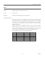
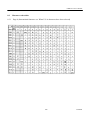
Number of columns
Font 1
Font 2
Standard size
Double height
Double wide
37
35
49
47
37
35
49
47
18
17
24
23
Double wide
and height
18
17
24
23
(Spaces between the characters are not included)
The figures on the top line show the situation when thermal paper is selected, and the figures on the bottom line
show the situation when thermal label paper is selected.
6
CITIZEN
CBM-253 User’s Manual
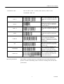
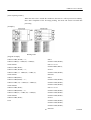
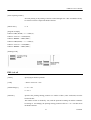
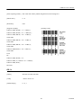
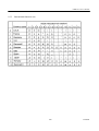
Available bar codes
UPC-A, UPC-E, JAN- 13 (EAN), JAN-8 (EAN), CODE 39, ITF,
CODABAR, CODE 128
Type
Printing samples
Features
UPC-A
This is a fixed-length bar code that is
composed of 12 figures of numerals
only.
UPC-E
This is a fixed-length bar code that is
composed of 8 figures of numerals
only. This bar code is a shortened
version of UPC-A.
JAN- 13
This is a fixed-length bar code that is
composed of 13 figures of numerals
only.
JAN-8
This is a fixed-length bar code that is
composed of 8 figures of numerals
only.
CODE 39
This is a variable -length bar code
that is composed of alphabetic
characters and numerals. The start
and stop ' * ' characters are attached
automatically.
ITF
This is an even-numbered variablelength bar code that is composed of
numerals only .
CODABAR
This is a variable -length bar code
that is composed of alphabetic
characters. For the start and stop
characters, one of 'abcd' is required.
CODE 128
This is a variable -length bar code
that is composed of any of the 128
ASCII code characters.
Bar code specification
Type/number of printing figures/bar code height/horizontal width (enlargement) /
presence of visible code Printing will be carried out according to the bar code data
specifications.
7
CITIZEN
CBM-253 User’s Manual
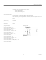
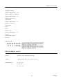
2.4 Paper specifications
Specified paper (Roll paper)
Thermal paper
Paper width
: 60.0 mm± 01mm
Paper thickness
: 65±5µm
Diameter of paper roll
: φ83 mm maximum
Recommended paper
: TF50KS-EY Nihon Seishi Co., Ltd.
: TF50KS-E2C Nihon Seishi Co., Ltd.
Roll paper core
: Internal diameter φ12.0 mm
: External diameter φ18.0 mm
* Absolutely do not stick the paper to the core.
* The printing surface should be outside.
Printing area
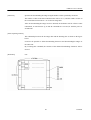
Thermal label paper
Paper width Paper thickness
: 60.0 mm± 01mm
: 150µm maximum
(Base paper thickness + Label thickness)
Diameter of paper roll
: φ83 mm maximum
Label size
: Minimum 25 mm ~ maximum 100 mm
Recommended paper
: HG76, HD75 Nihon Seishi Co., Ltd.
Roll paper core
: Internal diameter φ25.4 mm
: External diameter φ33.4 mm
* Absolutely do not stick the paper to the core.
* The printing surface should be outside.
8
CITIZEN
CBM-253 User’s Manual
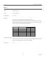
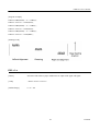
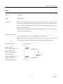
•
In order to allow the detection of the paper label length and label top position, cut-out holes should be
made between the paper labels according to the dimensions shown above.
•
Do not use label paper that has different dimensions from that shown above.
Printing area
Note:
Do not mix labels having different widths and length in the same roll of label paper.
Note : Have a surplus in the printing range in consideration of the flexing and the range of differences in the
printing paper.
9
CITIZEN
CBM-253 User’s Manual
2. 5 Interfaces
Serial interface (RS-232C)
Parallel interface
2. 6 Data buffer
4KB or 45B (Selectable by dip switch setting)
2. 7 Paper and sensor
Detection of whether there is paper or not. (Mechanical u nit)
Near-end detection (Paper holder unit)
2. 8 Auto-cutter
Rotary system, full cut type (AC-7)
Note:
Auto-cutter operation will not be possible while the printer is printing.
Note:
After switching on the printer. carry out cutting one time in order to determine the position.
Note:
In case of using thermal label paper, paste of label may stick to cutter blade.
2. 9 Drawer kick-out connector
Drawer kick-out drive terminal × 2
Detection of drawer open/close terminal × l
2. 10 Electrical specifications
Power source voltage
AC 120V+10% 50/60Hz
AC 230V+10% 50/60Hz
(Selected according to the product destination)
Power cable
Power consumption
For North America:
3-pin UL cable
For Europe:
3-pin Class 1 cable
Approximately 20W (during character printing)
Approximately 40W (during full printing)
10
CITIZEN
CBM-253 User’s Manual
2.11 External appearance specifications
Weight
Approximately 2.2kg
External dimensions Refer to 'External dimensions' at the end of this manual.
2.12 Environmental specifications
Temperature
Humidity
Operating temperature
5°C~40°C
Storage temperature
-10°C~50°C (Excluding the recording paper)
Operating humidity
35~80% (Non-condensing)
Storage humidity
30~90% (Non-condensing, excluding the recording paper)
2.13 Reliability specifications
Head lifetime
Pulse resistance
: 5 × 10⁷ pulses
Wear resistance
: 30 km
(At a printing rate of less than 25.0%, with a resistance value change rate of 15% or less.)
Cutter lifetime
500,000 cuts (At no paste of label on cutter blade.)
Please note that the above lifetime is not guaranteed value.
This value may change depending on installation environment of printer unit.
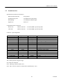
2.14 EMI standards and safety standards
FCC
Class A
VCCI
Type 1
UL
1950
EN
60950
11
CITIZEN
CBM-253 User’s Manual
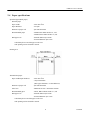
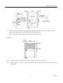
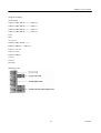
3.
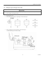
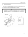
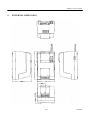
EXTERNAL APPEARANCE AND NAMES OF EACH PART
3.1
External appearance and part names
12
CITIZEN
CBM-253 User’s Manual
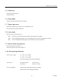
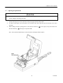
3.2
Explanation of each part
1 Power plug
This plug should be inserted into a power source outlet of the specified voltage.
2 Power switch
By setting this switch to ON, the printer initializati on operation will begin.
3 Power lamp
This lamp will be lit when the power switch is ON, and will be off when the power
switch is OFF.
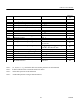
4 Alarm lamp
This lamp will light in the printer error condition. The lamp will flash to indicate
the printer condition during errors such as when the paper has run out, when the
head is open, or when the head is overheating, and will also flash when the printer
is in the condition of waiting for macro execution, etc.
Error display patterns
Error name
Printer cover open
Head up
Paper near-end
Paper end
Pattern of flashing
Lit
Off
Lit
Conditions for resetting
Close the cover
Head down
Set the paper
Set the paper
Off
Label detecting error
Set the specified label paper and then
switch the power on a again
Lit
Off
Memory checking error
Lit
Resetting not possible *1
Off
Head thermistor error
Lit
Resetting not possible *1
Off
Head overheating
Cutter motor locking
Lit
Automatic resetting when the
temperature lowers
Off
Lit
Resetting not possible *1
Off
Waiting for macro execution
Waiting for label ejection
Waiting for test printing
Waiting for cutter operation
Lit
Press the LF switch
Off
* 1 Contact service person.
13
CITIZEN
CBM-253 User’s Manual
5 LF switch
Pressing this switch carries out line feeding of the paper. When the printer is
waiting for macro execution, pressing this switch will carry out the execution.
When the power switch is switched on while this switch is being pressed, selfprinting will be carried out.
6 Interface connector
This interface allo ws connection with various types of personal computers using a
cable. When making the connection, the power of the personal computer and the
printer should be switched off.
7 External output connector This connector is used for control of the drawer.
8 Dip switches
These switches set the various functions.
9 Printer cover
This cover should be opened and closed when replacing the printing paper.
14
CITIZEN
CBM-253 User’s Manual
4.
OPERATION
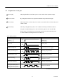
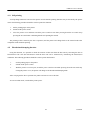
4.1
Opening the printer cover
The printer cover may be opened by inserting your hand into the paper outlet of the printer and lifting up the
cover in the direction shown by the arrow in the figure.
15
CITIZEN
CBM-253 User’s Manual
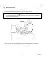
4.2
Opening the auto-cutter
To open the auto-cutter when the paper has become jammed in the printer or when the head is to be clean ed, life
up the auto-cutter while lifting the cutter locking lever in the direction shown by the arrow.
CAUTION
•
Do not touch the head or motor immediately after printing, since these parts will be very hot and there
will be a danger of burning your hand.
After closing the auto-cutter, check that the cutter unit is firmly fixed in the mechanism by the cutter locking
lever. If the cutter unit is not firmly fixed, this will become a cause of paper jamming.
16
CITIZEN
CBM-253 User’s Manual
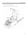
4.3
Setting the paper roll in the paper holder
Open the paper holder in the direction shown by the arrow and set the roll paper.
17
CITIZEN
CBM-253 User’s Manual
4.4
Loading the paper
1. Open the printer cover.
2. Cut the end of the roll of paper at right angles as shown in the figure.
3. Set the printing paper in the pape r holder as shown in the figure.
* Make sure that the paper roll rotates smoothly.
4. Make sure the winding direction of the paper roll is correct, then insert the end of the printing paper into the
paper inlet in the rear part of the printer. (Printing s urface should bc outside.)
5. Open the head-up lever (press it down forwards) to set the head up condition.
6. Use the knob to feed the printing paper up to the paper outlet.
7. Close the head-up lever. (Lift up the lever)
8. Close the printer cover.
18
CITIZEN
CBM-253 User’s Manual
4.5
Loading the paper when paper roll is small
CAUTION
•
Do not touch the head or motor immediately after printing, since these parts will be very hot and there
will be a danger of burning your hand.
1. Open the printer cover.
2. Cut the end of the roll of paper at rig ht angles as shown in the figure.
3. Set the printing paper in the paper holder as shown in the figure.
* Confirm that the paper roll rotates smoothly.
19
CITIZEN
CBM-253 User’s Manual
4. Lift up the auto-cutter lever to open the cutter.
5. Confirm the winding direction of the paper roll, then insert the end of the printing paper into the paper inlet
in the rear of the printer. (Note that printing surface should be outside.)
6. Open the head-up lever (press it down forwards) to set the head -up condition.
7. Using the knob, feed the printing paper until the paper comes out of the printer mechanism.
20
CITIZEN
CBM-253 User’s Manual
8. Pull the paper that has come out of the printer mechanism and pass it through the autocutter.
9. Close the auto-cutter while pulling the end of the paper that has passed through the auto -cutter.
10. Close the head-up lever.
11. Close the printer cover.
21
CITIZEN
CBM-253 User’s Manual
4. 6 Setting the printer cover back
Holding the printer cover in the approximately 90° open position, hook the right arm onto the right boss. Then
while pulling open the left arm, hook it on to the left boss to complete the mounting of the printer cover.
22
CITIZEN
CBM-253 User’s Manual
4. 7 Opening the print head
CAUTION
•
Do not touch the head or motor immediately after printing, since these parts will be very hot and there
will be a danger of burning your hand.
1. Switch OFF the power switch. and remove the power plug from the mains outlet.
2. As shown in the figure, open the printer cover and the auto-cutter and then press the head-up lever down
forwards.
3. While sliding the head opening knob in the direction shown by 1 in the figure, lift up the head in the
direction shown by 2 in the figure to open the head.
Note: This operation should only be carried out when cleaning the head or platen.
23
CITIZEN
CBM-253 User’s Manual
4. 8 Self-printing
A self-printing function is built in to this printer in order that the printing functions may be checked by the printer
itself. The following procedure should be used to operate this function:
1. Set the printing paper in the printer.
2. Switch off the power switch.
3. Close the printer cover and then switch the power switch to ON while pressing down the LF switch. Stop
pressing the LF switch after confirming that the self -printing has started.
The printing will be started by the above operation, and the printer will change back to the normal mode after
completion of the fixed line printing.
4.9
Hexadecimal dumping function
Using this function, it is possible to check the contents of data sent from the host unit by convening the data to
hexadecimal code. The data transmission with the host unit can be monitored by monitoring the transmission
conditions. The following procedure should be used to operate this function:
1.
Set the printing paper in the printer.
2.
Switch off the power switch.
3.
With the printer cover left open, switch the power switch to ON while pressing down the LF switch. By
closing the printer cover, the printer will change to the hexadecimal dumping mode.
After carrying out the above operation. the printer will wait to receive the data.
To exit from this mode, switch off the printer power.
24
CITIZEN
CBM-253 User’s Manual
4.10 Paper end detecting function
This printer includes functions that automatically detect when the remaining printing paper is running low and
stop the printing. The paper end detecting function detects when the paper has run out, and the paper near-end
detecting function detects when the remaining printing paper is running low.
The switching of the paper near-end detecting function between enabled and disabled is carried out using the
<ESC c 4> command. When this function is set to enabled, the setting of the paper length that is allowed between
the occurrence of the detection and the stopping of the printing should be carried out using the dip switches.
Note : In a situation in which the paper end is detected while printing on label paper, the data rema ining in the
receiving buffer may not be printed at the intended position on the label.
25
CITIZEN
CBM-253 User’s Manual
5.
INTERFACE SPECIFICATIONS
5.1
Serial interface
Specifications (Conform to RS-232C)
Synchronizing system
: Asynchronous system
Handshaking
: DTR/DSR control or Xon/Xoff control
Baud rates
: 1200, 4800, 9600, 19200 (Selected by the user)
Data length
: 7 or 8 bit length (Selected by the user)
Parity
: Odd/Even/None (Selected by the user)
Signal level
: Mark= -3 ~ -15V Logic '1'
: Space = +3 ~ +15V Logic '0'
Compatible interface connectors
Printer side
: 25-pin connector
17-13250 (DDK) equivalent product
Cable side
: 25-pin connector
17-23250 (DDK) equivalent product
Connector's pin configuration
Connector pin
1
2
3
6
20
7
Signal name
FG
TXD
RXD
DSR
DTR
SG
Input/output
–
Output
Input
Input
Output
–
Function
Frame ground
Sending data
Receiving data
Data set ready
Data terminal ready
Signal ground
Note: Shielded type cables should be used.
Explanation of input and output signals
(1) RxD
This is the serial receiving data signal. On the occurrence of framing errors, overrun errors or parity errors,
this data will either be rejected or printed as ' ?'. according to the DSW2-7 switch condition.
26
CITIZEN
CBM-253 User’s Manual
(2) DTR
When the DTR/DSR control has been selected, data or commands should be written when this signal is at
ready. If writing is carried out while this signal is at BUSY, an overrun error will occur and the data will be
ignored. Data can be written into the input buffer even when printing is being carried out.
(3) TXD
When receiving data while using Xon/Xoff control, an Xoff (13H) 'Data receiving not possible' signal will be
output when the remaining space of the input buffer inside the printer becomes less than 10 bytes. When the
input buffer remaining space become more than 20 bytes, an Xon (11H) 'Data receiving possible' signal will
be output. When sending status information while the DTR/DSR control is selected, confirm that the DSR is
at 'space' before sending the data. In the Xon/Xoff control, the data should be sent regardless of the DSR
condition.
(4) FG
This is a frame ground.
(5) SG
This is the common ground on the circuit board.
Receiving control
When DTR/DSR control has been selected, data will be received from the host when the DTR signal is at
'space' . Data receiving will not be possible when the DTR signal is at 'mark'.
When Xon/Xoff control has been selected, data will be received from the host side after the Xon signal has
been sent. However, data receiving will not be possible after the Xoff signal has been sent.
27
CITIZEN
CBM-253 User’s Manual
5.2
Parallel interface
Specifications (Conform to Centronics)
Data transmission format
: 8-bit parallel
Synchronizing system
: According to the strobe pulses
Handshaking
: According to the BUSY signal
Signal level
: TTL level
Compatible interface connectors
Printer side
: Ribbon connector
57-40360 (DDK) equivalent product
Cable side
: Ribbon connector
57-30360 (DDK) equivalent product
Connector' s pin configuration
Connector pin
l
2~9
10
11
12
13 (See note)
14-15
16
17
18
19-30
31
32
33
34
35 (See note)
36
Signal name
*STB
DATA 1-8
*ACK
BUSY
PE
+5V
N/C
GND
FG
N/C
GND
*RESET
* FAULT
GND
COMPULSION
+5V
N/C
Input/output
Input
Input
Output
Output
Output
Output
Function
Strobe signal
Input data
Request for next data
Processing is taking place
Paper end
+5V DC
Ground
Frame ground
Input
Output
Output
Output
Twisted pair return signals
Reset
Error
Ground
COMPULSION signal
+5V DC
The * mark represents a negative logic.
N/C means not connected.
Note: Shied type cables should be used.
Note: Pins 13 and 35 can not be used by the user (Pulled up by 3.3K )
28
CITIZEN
CBM-253 User’s Manual
Explanation of input and output signals
(1) Input signals
DATA 1~8
: 8-bit parallel signals (Positive logic)
* STB
: Strobe signal used when reading in 8-bit data (Negative logic)
* RESET
: Signal that reset the whole printer. (Negative logic)
(2) Output signals
* ACK
: This is an 8-bit data requesting signal that is output as a BUSY FAULT PE pulse signal
at the end of the BUSY signal. (Negative logic)
BUSY
: This signal indicates that the printer is in the BUSY condition. New data should be input
when this signal is LOW. (Positive logic)
FAULT
: This signal changes to LOW when the printer is in the alarm condition. At this time, all
of the control circuits in the printer will stop. (Negative logic)
PE
: This signal will be output when the printing paper runs out or runs low. (Positive logic)
COMPULSION : This signal outputs the drawer switch condition. When the switch is open, the signal will
be 'H' , and when the switch is shorted. the signal will be 'L' .
(3) Other signals
+5V
: GND N/C This is a +5V output that has been pulled-up by a 3 .3K resistance.
GND
: This is the common ground on the circuit.
N/C
: These pins are not connected.
Receiving control
When the BUSY signal is LOW, it will be possible to receive data from the host. When the BUSY signal is
HIGH, data receiving will not be possible.
29
CITIZEN
CBM-253 User’s Manual
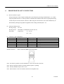
6.
DRAWER KICK-OUT CONNECTOR
(1) Drawer kick drive signal
The specified pulse will be output according to the specified pulse generating command (ESC <p>). When
using the parallel interface. it will be possible to determine the condition of the drawer opening and closing
switch from pin 34 of the interface connector. When using the serial interface. the switch condition may be
determined by utilizing the peripheral equipment status sending command (ESC <u>).
(2) Electrical characteristics
Driving voltage
: DC 24V
Driving current
: Maximum 1A (Should be less than 510 ms)
SW signal
: Signal level
'L' = 0~0.5V
'H' = 3~5V
(3) Connector' s pin configuration
Connector pin
Signal name
1
FG
2
L1
3
SW
4
Vp
5
L2
6
GND
Input/Output
–
Output
Input
–
Output
–
Function
Frame ground
Drawer l
Drawer opening and closing switch (* l)
Driving power source
Drawer 2
Signal ground
Used connector
285D-3660J- 100 (DDK)
Suitable connector
285D- 1660P-I06 (DDK) equivalent product
Note: It will not be possible to switch both drawer 1 and 2 to ON at the same time.
Note: Drawer operation will not be possible while the printer is printing.
Note: The duty should be kept to 20% or less.
Note: This connector is not to be used for connection to telephone lines.
30
CITIZEN
CBM-253 User’s Manual
WARNING!
•
Do not attempt to attach anything other than a solenoid, or to attach a solenoid having a resistance value
of less than 24Ω to the drawer drive terminal. The attachment of unspecified equipment may cause
breakdown of the equipment or heat damage to the solenoid, resulting in the danger of fire or electric
shock.
(*1)
Drawer opening and closing switch signal
This signal is pulled-up inside the printer using a resistance of 47KΩ.
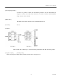
(4) Driving circuit (Inside of printer)
31
CITIZEN
CBM-253 User’s Manual
7.
DIP SWITCH SETTlNGS
The dip switches can be found inside the printer unit by remo ving the lower cover on the base chassis part. If the
screw of the lower cover is removed. it will be possible to change the dip switch settings.
WARNING!
•
Do not carry out setting of dip switches while the power plug is still plugged in to the power outlet,
since this action may cause breakdowns or the danger of electric shock. Do not remove any screws
other than the screws that fix the rear cover, since removing other screws may cause breakdowns or the
danger of electric shock.
32
CITIZEN
CBM-253 User’s Manual
1 DSW1 (Used commonly by the serial and parallel interfaces)
DSW1
1
2
3
4
5
6
7 (See note l)
8
ON
OFF
Printing density
(Refer to the table below.)
45 byte buffer
4K byte buffer
Thermal label paper
Thermal paper
Printing stopping position
after near-end detection
CR code valid
CR code invalid
Spare
Note 1 : The DSW1-7 function is only used for parallel interfaces.
Printing density
DSW 1-1
ON
OFF
ON
OFF
DSW1-2
ON
ON
OFF
OFF
Level
1
2
3
4
Density
Light
Dark
Printing stopping position setting after paper near-end detection when the paper near -end detection has been
enabled.
DSW1-5
ON
OFF
ON
OFF
DSW 1-6
ON
ON
OFF
OFF
Stopping position
0cm
50cm
100cm
200cm
33
CITIZEN
CBM-253 User’s Manual
2 DSW2 (Only mounted in serial interface printers)
DSW1
1
2
3
4
5
6
7
8
ON
Xon/Xoff control
Parity enabled
Even parity
7 bits
OFF
DTR/DSR control
No parity
Odd parity
8 bits
Baud rate
(Refer to the table below.)
Data rejected during
'?' character printed
a receiving error
during a receiving error
Spare
Baud rate
DSW2-5
ON
OFF
ON
OFF
DSW2-6
ON
ON
OFF
OFF
Baud rate
1200
4800
9600
19200
Note 2 : The dip switch setting only become valid at the time when the power is switched on. According, if the
setting are changed when the power is on, the switching will not be effe ctive.
34
CITIZEN
CBM-253 User’s Manual
8.
FUNCTIONS
8.1
Command table
Command
HT
LF
FF
CR
ESC SP
ESC !
ESC %
ESC &
ESC *
ESC
ESC 2
ESC 3
ESC =
ESC @
ESC D
ESC E
ESC G
ESC J
ESC R
ESC V
ESC a
ESC c 3
ESC c 4
ESC c 5
ESC d
ESC i
ESC p
Function
Code
Horizontal tab command
Printing, and paper line feeding
Printing, and moving to the top of the label
Printing command
Setting of the amount of space to the right of
the character
Block setting of the printing mode
Specifying/releasing of the downloading
character set
Defining of downloading characters
09H
0AH
0CH
0DH
Specifying of the bit image mode
Specifying/releasing of the underlining
Setting of the l/6 inch line feeding amount
Setting of the line feeding amount in
minimum paper feeding pitch units
Data input control
Printer initialization
Setting of the horizontal tab positions
Specifying/releasing of the highlighting
Specifying/releasing of the double printing
Printing, and paper feeding in minimum pitch
units
Selection of international characters
Specifying/releasing of 90° right turned
characters
Selection of printing position justification
Selection of the effective paper end detector
for output of the paper end signal
Selection of the effective paper end detector
for stopping the printing
Enabling/disabling of the panel switch
Printing, and line feeding of n lines
Full cutting
Specified pulse generation (Drawer kick out)
35
Reference
page
38
39
39
41
1BH 20H n
42
1BH 21H n
43
1BH 25H n
44
1BH 26H s n m
[a pl p2 · · · ps × a] m-n+1
1BH 2AH m n1 n2[d] k
1BH 2DH n
1BH 32H
48
50
51
1BH 33H n
52
1BH 3DH n
1BH 40H
1BH 44H [n]k 00H
1BH 45H n
1BH 47H n
53
54
55
56
57
1BH 4AH n
58
1BH 52H n
59
1BH 56H n
60
1BH G1H n
61
1BH 63H 33H n
62
1BH 63H 34H n
64
1BH 63H 35H n
1BH 64H n
1BH 69H
1BH 70H m n1 n2
65
66
67
68
46
CITIZEN
CBM-253 User’s Manual
Command
Function
ESC t
ESC v
ESC u
ESC {
ESC $
ESC ¥
GS FF
GS k
GS w
GS h
GS H
GS f
GS c
GS C0
GS C1
Selection of the character code table
Sending of the printer status
Sending of the peripheral equipment status
Specifying/releasing of inverted printing
Specifying of absolute positions
Specifying of relative positions
Printing, and label ejection (including cutting)
Bar code printing
Selection of bar code horizontal size
Selection of bar code height
Selection of visual code printing position
Selection of visual code font
Printing of counter
Setting of the numbering printing mode
Setting of the numbering counting mode (A)
GS C2
GS C;
Setting of the numbering counter
Setting of the numbering counting mode (B)
GS *
GS /
GS :
GS ^
GS <
GS A
GS R
Definition of the downloading/bit image
Printing of the downloading/bit image
Starting/finishing of the macro defining
Macro execution
Initialization of the printer mechanism
Correction of the label top position
Specifying/releasing of the black/white
inverted characters
Code
1BH 74H n
1BH 75H n
1PH 76H
1BH 7BH n
1BH 24H n1 n2
1BH 5CH n1 n2
1DH 0CH
1DH 6BH n ['d']k 00 H
1DH77H n
1DH 68H n
1DH 48H n
1DH 66H n
1DH 63H
1DH 43H 30H m n
1DH 43H 31H n1 n2
n3 n4 n5 n6
1DH 43H 32H n1 n2
1DH 43H 3BH "N 1" 3BH "N2" 3BH
"N3"3BH "N4"3BH "N5"3BH
1DH 2AH n1 n2[d]n1 × n2 × 8
1DH 2FH m
1DH 3AH
1DH 5EH n1 n2 n3
1DH 3CH
1DH 41H m n
1DH 52H n
Reference
page
69
70
71
72
73
75
76
77
82
83
83
84
86
87
89
92
95
95
98
99
100
101
102
105
Note : n, n1, n2, n3, m, a. s, p, and d in the table represent the parameters of each commend.
Note : [ ] k in the table represents a repetition carried ou t k times.
Note : ' ' in the table represents an ASCII character.
Note : " " in the table represents a string of ASCII characters.
36
CITIZEN
CBM-253 User’s Manual
8.2
Details of commands
8.2.1 How to read each section
xxxx
[Name]
This is the command name
[Code]
In the line up of codes making up the command, < >H indicates hexadecimal notation,
< >B indicates binary notation, and < > indicates decimal notation. [ ] k represents a
repetition carried out k times.
[Function]
This section indicates the function of the command.
[Item requiring caution]
When necessary, items that require caution are written in this section.
[Initial values]
For commands that are accompanied by arguments, the initial values are written in this
section.
[Reference]
Other commands related to the use of the command are written in this section.
[Program example]
Indicates a coding example using BASIC language.
[Printing result]
Indicates the printing result obtained by executing the program written above. However.
the scale reduction of the printing result given in this section will differ from that of the
actual printing result.
37
CITIZEN
CBM-253 User’s Manual
8.2.2 Detailed explanations
HT
[Name]
Horizontal tab command
[Code]
<09>H
[Function]
Moves the printing position to the next horizontal tab posit ion.
• This command will be disregarded if the next horizontal tab position has not been set.
[Item requiring caution]
• The horizontal tab positions should be set using ESC D.
• In the initial settings. the horizontal tab positions will bc set every 8 characters in font 1.
(At the 9th. 17th, and 25th columns.)
[Reference]
ESC D
[Program example]
LPRINT "0123456789012345678901" ;
LPRINT CHR$ (&HA) ;
LPRINT CHR$ (&H9) + "AAA" ;
LPRINT CHR$ (&H9) + "BBB" ;
LPRINT CHR$ (&HA) ;
LPRINT CHR$ (&H1B) + "D" ;
LPRINT CHR$(3) + C}R$(7) + CHR$(14) + CHR$(0) ;
LPRINT CHR$(&H9) + "AAA" ;
LPRINT CHR$ (&H9) + "BBB" ;
LPRINT CHR$ (&H9) + "CCC" + CHR$(&HA) ;
[Printing result]
38
CITIZEN
CBM-253 User’s Manual
LF
[Name]
Printing, and paper line feeding
[Code]
<0A>H
[Function]
Prints the data in the print buffer, and carries out line feeding based on the set line feeding
amount.
• The next printing start position will be at the head of the line.
[Reference]
ESC 2, ESC 3
[Program example]
[Printing result]
LPRINT "AAA" + CHR$ (&HA) ;
LPRINT "BBB" + CHR$(&HA) ;
LPRINT CHR$ (&HA) ;
LPRINT "CCC" + CHR$ (&HA) ;
FF
[Name]
Printing, and moving to the top of the label
[Code]
<0C>H
[Function]
Prints the data in the print buffer, and moves to the top of the next label.
[Items requiring caution]
• This command will only be effective when label printings has been selected.
• After sending a one-label portion of printing data, be sure to send an <FF> or <GS FF>
command.
39
CITIZEN
CBM-253 User’s Manual
• After the label paper has been deliberately moved by the user, it will not be possible to
correctly move to the top of the label using this command. Accordingly, carry out the
moving to the top of the label using the LF switch or by executing the <GS < >
command.
[Reference]
GS FF
[Program example]
LPRINT "AAA" + CHR$ (&HA) ;
LPRINT "BBB" + CHR$(&HA) ;
LPRINT CHR$(&H0C) ;
LPRINT "AAA" + CHR$ (&HA) ;
[Printing result]
40
CITIZEN
CBM-253 User’s Manual
CR
[Name]
Printing command
[Code]
<0D>H
[Function]
1 When DSW1-7 is OFF, this command will be disregarded.
2 When DSW1-7 is ON, the data in the print buffer will be printed, and line feeding will
be carried out based on the set line feeding amount.
• The next printing start position will be at the head of the line.
[Items requiring caution]
• This command will only be effective for parallel interface printers.
[Reference]
LF
[Program example]
LPRINT "AAA" + CHR$ (&HD) ;
LPRINT "BBB" + CHR$ (&HD) ;
LPRINT CHR$ (&HD) ;
LPRINT "CCC" + CHR$ (&HD) ;
[Printing result]
41
CITIZEN
CBM-253 User’s Manual
ESC SP n
[Name]
Setting of the amount of space to the right of the character
[Code]
<1B>H <20>H <n>
[Defined range]
0 ≤ n ≤ 32
[Function]
Sets the amount of space to the right of the character in dot units (1/203 inch units).
[Items requiring caution]
In double wide mode, the amount of space to the right of the character will become two
times the set amount.
[initial value]
n=0
[Program example]
LPRINT CHR$ (&H1B) + " " + CHR$ (0) ;
LPRINT "AAAAA" + CHR$ (&HA) ;
LPRINT CHR$(&H1B) + " " + CHR$(1) ;
LPRINT "AAAAA" + CHR$ (&HA) ;
LPRINT CHR$(&H1B) + " " + CHR$(12);
LPRINT "AAAAA" + CHR$ (&HA) ;
[Printing result]
42
CITIZEN
CBM-253 User’s Manual
ESC ! n
[Name]
Block setting of the printing mode
[Code]
<1B>H <21>H <n>
[Defined range]
0 ≤ n ≤ 255
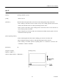
[Function]
Specifies the printing mode.
Bit
0
1
2
3
4
5
6
7
Value
Function
Character font
Not defined
Not defined
Highlighting
Double height
enlargement
Double wide
enlargement
Not defined
Underlining
0
Font l
1
Font 2
Release
Specify
Release
Specify
Release
Specify
Release
Specify
[Items requiring caution]
By specifying both the double height enlargement and the double wide enlargement, the
double wide and double height enlarged character will be formed. Although underlining
will be applied to the full width of the printing characters. underlining will not be applied
to parts that have been skipped using the HT command. Further, underlining will also not
be applied to characters that h ave been rotated 90° rightward.
The width of the underlining will be the width that has been specified using <ESC ->.
(The default will be a 1 dot width.) In a situation where double height enlarged characters
and ordinary characters are mixed together on one line. a layout will be adopted in which
the underlining will coincide.
43
CITIZEN
CBM-253 User’s Manual
[Initial value]
n=0
[Reference]
ESC E, ESC –
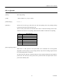
[Program example]
LPRINT CHR$(&H1B)
+ "!"+ CHR$ (&H00)
+ "H " ;
LPRINT CHR$ (&H1B) + "!" + CHR$(&H01)
+ "H " ;
LPRINT CHR$(&H1B)
+ "!"+ CHR$ (&H08)
+ "H " ;
LPRINT CHR$(&H1IB) + "! "+ CHR$(&H10)
+ "H " ;
LPRINT CHR$(&H1B)
+ "!"+ CHR$ (&H20)
+ "H " ;
LPRINT CHR$(&H1B)
+ "!"+ CHR$(&H80)
+ "H " ;
LPRINT CHR$(&H1B)
+ "!"+ CHR$ (&HB9)
+ "H " ;
LPRINT CHR$ (&HA) ;
[Printing result]
ESC % n
[Name]
Specifying/releasing of the downloading character set
[Code]
<1B>H <25>H <n>
[Defined range]
0 ≤ n ≤ 255
44
CITIZEN
CBM-253 User’s Manual
[Function]
Specifies or releases the downloading character set.
• Only the lowest bit of n will be valid.
When n = <*******1>B, the downloading character set is specified.
When n = <*******0>B, the downloading character set is released.
(Specifies the internal character set)
[Items requiring caution]
It will not be possible to define downloading characters and downloading bit images at
the same time.
[Initial value]
n=0
[Reference]
ESC &
[Program example]
GOSUB SETCHR
DATA 6
LPRINT CHR$(&H1B) + "%" + CHR$ (0) ;
DATA &HFF, &H80, &H00
LPRINT "@A" + CHR$ (&HA) ;
DATA &H80, &H80, &H00
LPRINT CHR$ (&H1B) + "%" + CHR$ (1) ;
DATA &H80. &H80, &H00
LPRINT "@A" + CHR$(&HA) ;
DATA &H80. &H80, &H00
END
DATA &HFF, &HFF, &HFF
SETCHR :
DATA &HFF, &HFF, &HFF
LPRINT CHR$ (&H1B) + "&" ;
DATA 12
LPRINT CHR$ (3) + "@" + "A" ;
DATA &HFF, &HFF, &HFF
FOR J=1 TO 2
DATA &H80, &H07, &HF9
READ REP
DATA &H80, &HFF, &HF9
LPRINT CHR$ (REP) ;
DATA &H87, &HFE, &H01
FOR I=1 TO REP*3
DATA &H9F, &H06, &H0l
READ D
DATA &HF8. &H06, &H01
LPRINTCHR$ (D) ;
DATA &HF8. &H06, &H01
NEXT I
DATA &H9F, &H06, &H01
NEXT J
DATA &H87, &HFE, &H0l
RETURN
DATA &H80, &HFF, &HF9
DATA &H80, &H07, &HF9
DATA &HFF, &HFF, &HFF
45
CITIZEN
CBM-253 User’s Manual
[Printing result]
ESC & s n m [a [p] s x a] m - n + 1
[Name]
Defining of downloading characters
[Code]
<1B>H <26>H <s> <n> <m> [<a> <p1> <p2> .....<ps x a>] m-n+ 1
[Defined ranges]
s=3
32 ≤ n ≤ m ≤ 126
0 ≤ a ≤ 12 (Font 1)
0≤a≤9
(Font 2)
0 ≤ p1 .... ps × a ≤ 255
[Function]
Defines the alphanumeric and Kana character downloading character font.
s indicates the number of bytes in the vertical direction.
n indicated the starting character code, and m indicates the finishing character code.
When defining only 1 character, n should be made equal to m.
The character codes that may be defined are the total of 95 characters of ASCII code
in the range between <20>H and <7E>H.
a indicates the number of dots defining the horizontal direction.
p is the data for defining, and indicates a pattern that is an a-pot portion from the left
margin in the horizontal direction. The remaining pattern to the right side will be filled
up with spaces, and the number of pieces of data for defining will be s × a.
Once the downloading characters have been defined, the characters will remain valid
until other characters are defined, or until the ESC @ or GS * commands are executed,
or until the power is switched off.
46
CITIZEN
CBM-253 User’s Manual
[Items requiring caution]
It will not be possible to define the downloading characters and the downloading bit
images at the same time. When this command is executed. the defined downloading bit
image contents will be cleared.
[Initial value]
The initial values will be the same as for the internal character set.
[Reference]
ESC %
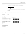
[Example]
Each bit of the data is made up of ' 1 ' dots that will be printed and '0' dots that will not be printed.
[Program example]
[Printing result]
Refer to the program example and the printing result for ESC % on page 45 -46.
47
CITIZEN
CBM-253 User’s Manual
ESC ∗ m n1 n2 [d] k
[Name]
Specifying of the bit image mode
[Code]
<1B>H <2A>H <m> <n1> <n2> [<d>] k
[Defined ranges]
m = 0, 1, 32, 33
0 ≤ n1 ≤ 255
0 ≤ n2 ≤ 3
0 ≤ d ≤ 255
k = n1 + 256 × n2
(m = 0, 1)
k = (n1 + 256 × n2) x 3 (m = 32, 33)
[Function]
This command specifies the bit image of mode m with regard to the number of dots
specified by n1 and n2.
• The number of dots for printing will be divided by 256, and the quotient will become
n2 with the remainder becoming n1, Accordingly, the number of dots in the horizontal
direction will be n1 + 256 × n2.
• In a situation where the bit image data input exceeds the dot positions that are capable
of being printed on one line, the portion of data in excess will be rejected for reading.
• d is the bit image data. When the data is to be printed, the corresponding bit should be
set to 1 , and data which is not to be printed should have the corresponding bit set to 0.
• The bit image mode selected using m will be as shown below :
Vertical direction
m
0
1
32
33
Mode
8-dots single density
8-dots double density
24-dot single density
24-dot double density
Number of dots
Dot density
8
8
24
24
67 DPI
67 DPI
203 DPI
203 DPI
48
Horizontal direction
Maximum
Dot density
number of dots
101 DPI
224
203 DPI
448
101 DPI
224
203 DPI
448
CITIZEN
CBM-253 User’s Manual
[Items requiring caution]
When the value of m is outside the conditions, data after n 1 will be processed as ordinary
data. After completion of the bit image printing, the mode will return to normal data
processing.
[Example]
Printing result
[Program example]
LPRINT CHR$ (&H1B) + "*" ;
IMG1:
LPRINT CHR$(0) + CHR$(20) + CHR$(0) ;
LPRINT CHR$ (&HFF) ;
GOSUB IMG1
FOR I=1 TO 18
LPRINT CHR$ (&HA) ;
LPRINTCHR$ (&H85) ;
LPRINT CHR$ (&H1B) + "*" ;
NEXT I
LPRINT CHR$ (1) + CHR$ (20) + CHR$ (0) ;
LPRINT CHR$ (&HFF) ;
GOSUB IMG1
RETURN
LPRINT CHR$(&HA) ;
IMG2 :
LPRINT CHR$(&H1B) + "*" ;
LPRINT CHR$ (&HFF) ;
LPRINT CHR$ (32) + CHR$ (20) + CHR$ (0) ;
LPRINT CHR$ (&HFF) ;
GOSUB IMG2
LPRINT CHR$ (&HFF) ;
LPRINT CHR$ (&HA) ;
FOR I=1 TO 18
LPRINT CHR$(&H1B) + "*";
LPRINT CHR$ (&H80) ;
LPRINT CHR$(33) + CHR$ (20) + CHR$(0) ;
LPRINT CHR$ (&H00) ;
GOSUB IMG2
LPRINT CHR$ (&H05) ;
LPRINT CHR$ (&HA) ;
NEXT I
END
LPRINT CHR$ (&HFF) ;
LPRINT CHR$ (&HFF) ;
LPRINT CHR$ (&HFF) ;
RETURN
49
CITIZEN
CBM-253 User’s Manual
[Printing result]
ESC - n
[Name]
Specifying/releasing of the underlining
[Code]
<1B>H <2D>H <n>
[Defined ranges]
0≤n≤2
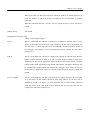
[Function]
Specifies and releases the underlining.
n = 0 Releases the underlining
n = 1 Specifies 1 dot width underlining
n = 2 Specifies 2 dot width underlining
[Items requiring caution]
Although the underlining will be applied to the full width of the printing characters.
underlining will not be applied to parts that have been skipped using the HT command.
Underlining will not be applied to characters that have been rotated 90° rightward.
[Reference]
ESC !, FS -
[Program example]
[Printing result]
LPRINT CHR$ (&H1B) + " " + CHR$(0);
LPRINT "AAAAA" ;
LPRINT CHR$(&H1B) + "-" + CHR$(1) ;
LPRINT "AAAAA" + CHR$ (&HA) ;
50
CITIZEN
CBM-253 User’s Manual
ESC 2
[Name]
Setting of the 1/6 inch line feeding amount
[Code]
<1B>H <32>H
[Function]
Sets the line feeding amount to l/6 inch for each 1 line.
[Program example]
[Printing result]
LPRINT "AAAAA" + CHR$ (&HA) ;
LPRINT CHR$(&H1B) + "3" + CHR$(0) ;
LPRINT "AAAAA" + CHR$ (&HA) ;
LPRINT CHR$ (&H1B) + "3" + CHR$(50) ;
LPRINT "AAAAA" + CHR$(&HA) ;
LPRINT CHR$ (&H1B) + "2" ;
LPRINT "AAAAA" + CHR$(&HA) ;
LPRINT "AAAAA" ;
LPRINT CHR$(&H1B) + "J" + CHR$(l00) ;
LPRINT "AAAAA" + CHR$ (&HA) ;
LPRINT "AAAAA" + CHR$(&HA) ;
51
CITIZEN
CBM-253 User’s Manual
ESC 3 n
[Name]
Setting of the line feeding amount in minimum paper feeding pitch units
[Code]
<1B>H <33>H <n>
[Defined range]
0 ≤ n ≤ 255
[Function]
Sets the line feeding amount to n/203 inch for each 1 line.
[Items requiring caution]
When label printing has been specified. if line feeding is carried out by specifying a paper
feeding amount in excess of the label length. the line feeding will be carried out up to the
position at the top of the following label. Because the printing will be accompanied by
line feeding, even if printing is carried out when a smaller value than the line feeding
amount of 1 line has been set. line feeding of more than the set amount may be carried out
due to the printing operation.
[Initial value]
n = 34 (1/6 inch)
[Program example]
[Printing result]
Refer to the program example and the printing result for ESC 2 on page 51.
52
CITIZEN
CBM-253 User’s Manual
ESC = n
[Name]
Data input control
[Code]
<1B>H <3D>H <n>
[Defined range]
0 ≤ n ≤ 255
[Function]
Selects the effective equipment for data input from the host unit.
Each bit of n has the meaning shown in the table below. When the printer is in the deselected condition, the printer will reject reading any of the received data until the printer
has been set to the selected condition using this command.
Bit
0
1
2
3
4
5
6
7
Function
Printer
Not defined
Not defined
Not defined
Not defined
Not defined
Not defined
Not defined
Value
0
Invalid
1
Valid
[Items requiring caution]
It will be possible that the printer will change to the BUSY condition due to the printer
operation even while the printer is in the de-selected condition.
[Initial value]
n=1
53
CITIZEN
CBM-253 User’s Manual
[Program example]
[Printing result]
LPRINT "AAAAA" ;
LPRINT CHR$ (&HIB) + "=" + CHR$ (0) ;
LPRINT "aaaaa" + CHR$ (&HA) ;
LPRINT CHR$(&HIB) + "=" + CHR$(1) ;
LPRINT "AAAAA" + CHR$ (&HA) ;
Esc @
[Name]
Printer initialization
[Code]
<1B>H <40>H
[Function]
Clears the data in the print buffer, and sets various settings to the initial conditions.
(Default conditions)
[Items requiring caution]
The setting contents of the dip switches will not be read in again during this operation.
The data in the receiving buffer will not be cleared during this o peration.
[Program example]
[Printing result]
LPRINT CHR$ (&H1B) + " !" + CHR$ (&H30) ;
LPRINT CHR$(&H1B) + "V" + CHR$(1);
LPRINT "AAA" + CHR$ (&HA) ;
LPRINT CHR$ (&H1B) + "@" ;
LPRINT "AAA" + CHR$ (&HA) ;
54
CITIZEN
CBM-253 User’s Manual
ESC D [n] k NUL
[Name]
Setting of the horizontal tab positions
[Code]
<1B>H <44>H [<n>] k <00>H
[Defined ranges]
1 ≤ n ≤ 255
0 ≤ k ≤ 32
[Function]
Sets the horizontal tab positions. n indicates the number of columns from the head of the
line to the position that the horizontal tab is to be set. Because 'n = setting columns
position - 1 ' , for an example in which the horizontal tab is to be set at the 9th column, n
should be set to 8.
k indicates the number of horizontal tab positions to be set. Although the tab positions
will be set at positions that are (n × the character width) from the head of the line, the
character width in this case will include the amount of space to the right of the character.
Further, when the two-times horizontal character enlargement has been specified, the tab
position spacing will become twice wider than normal.
Tab positions may be set to a maximum of 32 locations, and tab position settings in
excess of this number will be disregarded.
The <n> k data that indicates the setting positions should be input in order from the
smallest value first, and should finish with <00>H.
The ESC <D NUL> command clears all the set tab positions. HT commands executed
after all the tabs have been cleared will be disregarded.
55
CITIZEN
CBM-253 User’s Manual
[Items requiring caution]
If the <n> k data is the same value or is smaller than the immediately previous <n> k - 1
data, the tab setting will be regarded as having been completed. In this situation,
subsequent data will be processed as normal data.
If the <n> k data exceeds the printing range of one line, the data will be set as the 'Set
figure position = Maximum printing figure +1'.
After setting the horizontal tab positions, the horizontal tab positions will not change even
when the character width is changed.
[Initial value]
Tabs will be set at every 8 characters in font 1. (At the 9th, 17th, 25th columns)
[Reference]
HT
[Program example]
[Printing result]
Refer to the program example and printing result for HT on page 38.
ESC E n
[Name]
Specifying/releasing of the highlighting
[Code]
<1B>H <45>H <n>
[Function]
Specifies and releases the highlighting.
• When n = <*******0>B. the highlighting will be released.
• When n = <*******1>B. the highlighting will be specified.
This command will be effective for all types of character. The highlighting will add one
dot horizontally to each dot of the character.
[Reference]
ESC !
56
CITIZEN
CBM-253 User’s Manual
[Example]
[Program example]
[Printing result]
LPRINT CHR$ (&H1B) + "E" + CHR$ (0) ;
LPRINT "AAABBB" + CHR$ (&HA) ;
LPRIT CHR$(&H1B) + "E" + CHR$(1) ;
LPRlNT "AAABBB" + CHR$(&HA) ;
ESC G n
[Name]
Specifying/releasing of the double printing
[Code]
<1B>H <47>H <n>
[Function]
Specifies and releases the double printing.
• When n = <*******0>B, the double printing will be released.
• When n = <*******1>B, the double printing will be specified.
This command will be effective for all character types.
[Items requiring caution]
In this printer, the double printing and highlighting will be absolutely identical.
[Reference]
ESC E
57
CITIZEN
CBM-253 User’s Manual
[Program example]
[Printing result]
LPRINT CHR$ (&H1B) + "G" + CHR$ (0) ;
LPRINT "AAABBB" + CHR$ (&HA) ;
LPRINT CHR$ (&H1B) + "G" + CHR$ (1) ;
LPRINT "AAABBB" + CHR$(&HA) ;
ESC J n
[Name]
Printing, and paper feeding in minimum pitch units
[Code]
<1B>H <4A>H <n>
[Defined range]
0 ≤ n ≤ 255
[Function]
Prints the data in the printer buffer, and then carries out paper feeding of n/203 inch. The
set paper feeding value will not remain after this function has been carried out.
The next printing start position will be the head of the line. When label printing has been
selected, if the specified paper feeding amount exceeds the label length. the line feeding
will be carried out up to a position at the top of the following label. Because the printing
will be accompanied by line feeding, even if printing is carried out when a smaller value
than the line feeding amount of 1 line has been set, line feeding of more than the set
amount may be carried out due to the printing operation.
[Initial value]
Not defined.
[Program example]
[Printing result]
Refer to the program example and the printing result for ESC 2 on page 51.
58
CITIZEN
CBM-253 User’s Manual
ESC R n
[Name]
Selection of international characters
[Code]
<1B>H <52>H <n>
[Defined range]
0 ≤ n ≤ 10
[Function]
Selects the character sets of the countries shown in the table below according to the n
value.
n
0
1
2
3
4
5
6
7
8
9
10
Character set
U.S.A
France
Germany
U.K.
Denmark I
Sweden
Italy
Spain
Japan
Norway
Denmark II
[Initial value]
n=0
[Reference]
See the character code tables (International character sets)
59
CITIZEN
CBM-253 User’s Manual
[Program example]
[Printing result]
FOR I=0 TO 10
LPRINT CHR$ (&H1B) + "R" + CHR$ (1) ;
LPRINT " #$@[¥]^";
LPRINT CHR$ (&H60) + " {¥} Ø " ;
LPRINT "n =" + STR$ (1) ;
LPRINT CFR$(&HA) ;
NEXT I
ESC V n
[Name]
Specifying or releasing of 90° right turned characters
[Code]
<1B>H <56>H <n>
[Defined range]
0≤n≤1
[Function]
Specifies or releases the character 90° rightward rotation.
n = 1 Specifies character 90° rightward rotation.
n = 0 Releases character 90° rightward rotation.
[Items requiring caution]
Underlining can not be applied to characters that have been rotated 90° rightward.
[Initial value]
n=0
60
CITIZEN
CBM-253 User’s Manual
[Program example]
[Printing result]
LPRINT CHR$ (&H1B) + "V" + CHR$ (0) ;
LPRINT "AAAAA" ;
LPRINT CHR$(&H1B) + "V" + CHR$(1) ;
LPRINT "AAAAA" + CHR$(&HA) ;
ESC a n
[Name]
Selection of printing position justification
[Code]
<1B>H <61>H <n>
[Defined ranges]
0≤n ≤2
[Function]
Aligns all the printing data on one line to the specified position.
The position aligning will be carried out according to the n value as shown in the table
below.
n
0
1
2
Position
Left end aligning
Centering
Right end aligning
[Items requiring caution]
This command will only be valid when it has been input at the head of the line.
[Initial value]
n=0
61
CITIZEN
CBM-253 User’s Manual
[Program example]
LPRINT CHR$(&H1B) + "a" + CHR$(0) ;
LPRINT "AAAAA" + CHR$ (&HA) ;
LPRINT CHR$(&H1B) + "a" + CHR$(1) ;
LPRINT "AAAAA" + CHR$ (&HA) ;
LPRINT CHR$(&H1B) + "a" + CHR$(2) ;
LPRINT "AAAAA" + CHR$(&HA) ;
[Printing result]
ESC c 3 n
[Name]
Selection of the effective paper end detector for output of the paper end signal
[Code]
<1B>H <63>H <33>H <n>
[Defined range]
0 ≤ n ≤ 255
62
CITIZEN
CBM-253 User’s Manual
[Function]
Selects which of the paper end detector conditions will be used for the paper end signal
output.
Each bit of n will have the meanings shown in the table below.
Bit
0
1
2
3
4
5
6
7
Value
Function
Journal near-end
Not defined
Not defined
Not defined
Not defined
Not defined
Not defined
Not defined
0
Disabled
1
Enabled
In this printer, only one type of paper near-end detector can be selected for the paper end
detection, and only the lowest bit of n will be effective .
[Items requiring caution]
This command will only be effective for parallel interface printers .
[Initial value]
n=1
[Program example]
Situation in which the no paper signal is
output by the paper end detector.
LPRINT CHR$ (&H1B) + "c3" + CHR$ (0) ; LPRINT CHR$(&H1B) + "c3" + CHR$ (1) ; Situation in which no paper signal is
output by the paper near-end detector.
63
CITIZEN
CBM-253 User’s Manual
ESC c 4 n
[Name]
Selection of the effective paper end detector for stopping the printing
[Code]
<1B>H <63>H <34>H <n>
[Defined range]
0 ≤ n ≤ 255
[Function]
Selects which of the paper end detector conditions will be used for the paper end signal
output.
Each bit of n will have the meanings shown in the table below.
Bit
0
1
2
3
4
5
6
7
Value
Function
Journal near-end
Not defined
Not defined
Not defined
Not defined
Not defined
Not defined
Not defined
0
Disabled
1
Enabled
In this printer, only one type of paper near-end detector can be selected for the paper end
detection, and only the lowest bit of n will be effective.
[Items requiring caution]
When the printing stopping is set to enabled, the printing stopping position will be the
position set by the DSW1-5 and DSW1-6 switches. After the printing has been stopped,
the printer will change to the off-line condition.
[Initial value]
n=0
64
CITIZEN
CBM-253 User’s Manual
[Program example]
Situation in which the printing has been
stopped by the paper end detector.
LPRINT CHR$ (&H1B) + "c4" + CHR$ (0) ; LPRINT CHR$ (&H1B) + "c4" + CHR$ (1) ; Situation in which the printing has been
stopped by the paper near-end detector.
ESC c 5 n
[Name]
Enabling/disabling of the panel switch
[Code]
<1B>H <63>H <35>H <n>
[Defined range]
0 ≤ n ≤ 255
[Function]
Changes the LF switch between enabled and disabled.
• Only the lowest bit of n will be effective.
When n = <*******0>B, the LF switch will be enabled.
When n = <*******1>B, the LF switch will be disabled.
[Items requiring caution]
When the panel switch has been disabled using this command, the LF switch will not be
effective. Accordingly, it will not be possible to execute line feeding by operation of the
LF switch.
[Initial value]
n=0
[Program example]
Situation in which the LF switch
operation is valid.
LPRINT CHR$(&H1B) + "c5" + CHR$ (0) ; LPRINT CHR$(&H1B) + "c5" + CHR$ (1) ; Situation in which the LF switch
operation is invalid.
65
CITIZEN
CBM-253 User’s Manual
ESC d n
[Name]
Printing. and line feeding of n lines
[Code]
<1B>H <64>H <n>
[Defined range]
0 ≤ n ≤ 255
[Function]
Prints the data in the print buffer, and carries out a n -line portion of line feeding.
The next printing start position will be at the head of the line. The setting amount will not
remain after this operation has been carried out.
When label printing has been selected, if the specified paper feeding amount exceeds the
label length, the line feeding will be carried out up to a position at the top of the following
label. Because the printing will be accompanied by line feeding, even if printing is carried
out when a smaller value than the line feeding amount of 1 line has been set, line feeding
of more than the set amount may be carried out due to the printing operation.
[Initial value]
Not defined.
[Program example]
[Printing result]
LPRINT "AAAAA" ;
LPRINT CHR$(&H1B) + "d" + CHR$(2) ;
LPRINT "AAAAA" + CHR$ (&HA) ;
66
CITIZEN
CBM-253 User’s Manual
ESC i
[Name]
Full cutting
[Code]
<1B>H <69>H
[Function]
When the thermal paper has been selected. this command executes a full cut of the
printing paper. When label paper has been selected, line feeding of the label will be
carried out up to the cutting position (between the labels), and then the label will be cut
and ejected by the autocutter.
After ejection of the label, paper feeding will be carried out in the reverse direction to
move to the top of the next label.
[Items requiring caution]
This command will only be effective when input at the head of the line.
When thermal paper has been selected, make sure to feed the paper over 18mm before
cutting the paper. Because characters right after printing are left inside of the cutter.
[Program example]
[Printing result]
LPRINT "AAAAA" ;
LPRINT CHR$(&H1B) + "J" ;
LPRINT CHR$ (150) ;
LPRINT CHR$ (&H1B) + " i" ;
LPRINT "AAAAA" ;
LPRINT CHR$(&H1B) + "J" ;
LPRINT CHR$ (150) ;
LPRINT CHR$ (&H1B) + " i" ;
67
CITIZEN
CBM-253 User’s Manual
ESC p m n1 n2
[Name]
Specified pulse generation
[Code]
<1B>H <70>H <m> <n1> <n2>
[Defined ranges]
m= 0, 1
0 ≤ n1 ≤ n2 ≤ 255
[Function]
Outputs the signals specified by nl and n2 to the connector pin m. The types of m pins are
according to the table below.
m
0
1
Connector pin
Drawer kick No. 2 pin (Drawer kick-out terminal 1)
Drawer kick No. 5 pin (Drawer kick-out terminal 2)
The ON time will be n 1 × 2ms, and the OFF time will be n2 × 2ms.
[Items requiring caution]
If m is outside the defined range, n1 and n2 will be rejected for reading and the signal will
not output.
It is essential that the driving duty of the drawer should be within the following range.
(ON time/(ON time + OFF time)) ≤ 0.2
(The OFF time should be at least 4 times more than the ON time.)
[Initial values]
None of the values of m, n1 and n2 are defined.
[Program example]
LPRINT CHR$(&H1B) + "p"
LPRINT CHR$ (0) ; .....................Selection of the No. 2 pin
LPRINT CHR$ (5) ; .....................The ON time is set to 10ms
LPRINT CHR$ (50) ; ....................The OFF time is set to 100ms
68
CITIZEN
CBM-253 User’s Manual
ESC t n
[Name]
Selection of the character code table
[Code]
<1B>H <74>H <n>
[Defined range]
0≤n≤1
[Function]
Selects page n of the character code tables. The character code table will be selected
according to the value of n.
n
0
Character code page
Page 0(IBM character #2)
[Initial value]
n=0
[Reference]
See the character code tables.
[Program example]
[Printing result]
LPRINT CHR$(&H1B) + "t"+ CHR$(0) ;
LPRINT "n = 0" ;
FOR C=&HB1 T0 &HB5
LPRINT CHR$(C) ;
NEXT C
LPRINT CHR$ (&HA) ;
LPRINT CHR$(&H1B) + "t"+ CHR$(1) ;
LPRINT "n = 1 " ;
FOR C=&HB1 TO &HB5
LPRINT CHR$(C) ;
NEXT C
LPRINT CHR$ (&HA) ;
69
CITIZEN
CBM-253 User’s Manual
ESC v
[Name]
Sending of the printer status (only Serial interface)
[Code]
<1B>H <76>H
[Function]
Sends the status of the printer at the current point of time.
[Items requiring caution]
The status that is sent will be 1 byte of data, and the contents will be as shown in the table
below. When the control is set to DTR/DSR, 1 byte only should be sent after confirming
that the host is in the receiving possible condition (the DSR signal is at 'space'). Further,
when the control is set to XON/XOFF, one byte only should be sent without confirming
the DSR signal condition.
When the control is set to DTR/DSR and the host is in the receiving not possible
condition (the DSR signal is at 'mark'), wait until the DSR signal is in the receiving
possible condition. In the paper end (paper near-end) condition, there may be instances in
which receiving of this command may not be possible due to the BUSY condition.
This command will only be effective in serial interface printers .
Bit
0
1
2
3
4
5
6
7
Function
Paper near-end
Not defined
Paper end
Not defined
Not used
Not defined
Not defined
Not defined
0
Paper present
1
No paper
Paper present
No paper
Fixed at 0
70
CITIZEN
CBM-253 User’s Manual
[Program example]
OPEN "COM1 :N81NN" AS #1
PRINT #1,CHR$ (&H1B) + "v" ;
A$ = INPUT$(1,#1)
CLOSE #1
ESC u n
[Name]
Sending of the peripheral equipment status (Only serial interface)
[Code]
<1B>H <75>H <n>
[Defined range]
n=0
[Function]
Send the status of connector pin 3 at the current point of time. The types of n are
according to the table below.
n
0
Connector pin
Drawer kick connector pin No. 3 (Drawer open/close detection terminal).
[Item requiring caution]
The status that is sent will be 1 byte of data, and the contents will be as shown in the table
below. When there is no equipment connected to the connector, bit 0 of n will always be
'1'.
When the control is set to DTR/DSR, 1 byte only should be sent after confirming that the
host is in the receiving possible condition (the DSR signal is at 'space'). Further, when the
control is set to XON/XOFF, one byte only should be sent without confirming the DSR
signal condition.
When the control is set to DTR/DSR and the host is in the receiving not possible
condition (the DSR signal is at 'mark'), wait until the DSR signal is in the receiving
possible condition.
71
CITIZEN
CBM-253 User’s Manual
This command will only be effective in serial interface printers .
[Initial value]
Value
Bit
Function
0
1
2
3
4
5
6
7
Level of pin No. 3
Not defined
Not defined
Not defined
Not used
Not defined
Not defined
Not defined
0
'L'
1
'H'
Fixed at 0
Not defined
[Program example]
OPEN "COM1:N81NN" AS #1
PRINT #1,CHR$(&H1B) + "u" + CHR$(0) ;
A$ = INPUT$(1,#1)
CLOSE #1
ESC { n
[Name]
Specifying/releasing of inverted printing
[Code]
<1B>H <7B>H <n>
[Defined range]
0 ≤ n ≤ 255
[Function]
Specifies and releases the inverted printing.
• Only the lowest bit of n will be effective.
n = <*******1>B Specifies inverted printing
n = <*******0>B Releases inverted printing
72
CITIZEN
CBM-253 User’s Manual
[Items requiring caution]
Inverted printing is the printing of the line rotated through 180 °. This command will only
be effective when it is input at the head of the line.
[Initial value]
n=0
[Program example]
LPRINT CHR$ (&H1B) + "l" + CHR$ (0) ;
LPRINT "AAAAA" + CHR$ (&HA) ;
LPRINT "BBBBB" + CHR$ (&HA) ;
LPRINT CHR$(&H1B) + " l" + CHR$(1) ;
LPRINT "AAAAA" + CHR$(&HA) ;
LPRINT "BBBBB" + CHR$ (&HA) ;
[Printing result]
ESC $ n1 n2
[Name]
Specifying of absolute positions
[Code]
<1B>H <24>H <n1><n2>
[Defined ranges]
0 ≤ n1 ≤ 255
0 ≤ n2 ≤ 1
[Function]
Specifies the printing starting position as a number of dots (1/203 inch units) from the
head of the line.
The number of dots is divided by 256, with the quotient becoming n2 and the remainder
becoming n1. Accordingly, the printing starting position will be n1 + n2 × 256 dots from
the head of the line.
73
CITIZEN
CBM-253 User’s Manual
The number of the dots can be specified is as follows.
447 dot (Thermal paper)
423 dot (Thermal label paper)
[Items requiring caution]
Specifications that exceed the end of the line will be disregarded.
When underlining has been specified. the underlining will not be applied to the moved
portion.
[Initial value]
Not defined
[Reference]
ESC ¥
[Program example]
[Printing result]
LPRINT CHR$ (&H1B) + "$" ;
LPRINT CHR$ (0) + CHR$ (0) + "A" ;
LPRINT CHR$ (&H1B) + "$" ;
LPRINT CHR$ (50) + CHR$ (0) + "B" ;
LPRINT CHR$ (&H1B) + "$" ;
LPRINT CHR$(0) + CHR$(1) + "C";
LPRINT CHR$ (&HA) ;
LPRINT CHR$(&H1B) + "$";
LPRINT CHR$ (100) + CHR$(0) + "A" ;
LPRINT CHR$ (&H1B) + "¥" ;
LPRINT CHR$ (&HC2) + CHR$ (&HFF) + "B" ;
LPRINT CHR$ (&HA) ;
74
CITIZEN
CBM-253 User’s Manual
ESC ¥ n1 n2
[Name]
Specifying of relative positions
[Code]
<1B>H <5C>H <n1><n2>
[Defined range]
0 ≤ n1 ≤ 255
0 ≤ n2 ≤ 255
[Function]
Specifies the printing starting position as a number of dots (1/203 inch units) from the
current position. The right direction should be plus and the left direction should be minus.
When specifying N dots in the minus direction, the specifying should be carried out using
the complement of N.
-N dots = 65536 – N
The number of dots should be divided by 256, with the quotient becoming n2 and the
reminder becoming n1.
[Items requiring caution]
Specifications that exceed the beginning or the end of the line will be disregarded. When
underlining has specified, the underlining will not be applied to the moved portion.
[Initial value]
Not defined
[Reference]
ESC $
[Program example]
[Printing result]
Refer to the program example and the printing result for ESC $ on pa ge 74.
75
CITIZEN
CBM-253 User’s Manual
GS FF
[Name]
Printing, and label ejection
[Code]
<1D>H <0C>H
[Function]
Prints the data in the print buffer, and carries out the cutting and ejecting of the label.
• Line feeding of the label will be carried out up to the cutting position (between the
labels), then the label will be cut and ejected using the auto -cutter.
• After ejection of the label, paper feeding will be carried out in the reverse direction to
move to the top of the next label.
• After setting the top of the next label, the alarm LED will flash, and the printer will wait
until the LF switch is pressed.
[Items requiring caution]
• After confirming that the alarm LED is flashing. press the LF switch one time.
• This command will only be effective when label printing has been selected.
• After sending a one-label portion of printing data. it is essential to send the <FF>
command or <GS FF> command.
[Reference]
FF
[Program example]
[Printing result]
LPRINT "LABEL 1" ;
LPRINT CHR$ (&H1D) + CHR$(&HC) ;
76
CITIZEN
CBM-253 User’s Manual
GS k n [d]k NUL
[Name]
Bar code printing
[Code]
<1D>H <6B>H <n> [<d>] k <00>H
[Defined range]
0≤n≤7
[Function]
Selects the bar code type, and carries out bar code printing. The next printing starting
position will be taken as the head of the line.
The bar code systems shown in the table below will be selected according to the n value.
d indicates the characters for printing. and k shows the number of characters for printing.
n
0
1
2
3
4
5
6
7
Bar code type
UPC-A
UPC-E
JAN-13 (EAN)
JAN-8 (EAN)
CODE 39
ITF
CODABAR (NW-7)
CODE 128
[Items requiring caution]
When there is data present in the print buffer, this command will be disregarded.
Regardless of the currently set line feeding amount, only the line feeding required for the
bar code printing will be carried out.
In each of the bar code type, when the character code d contains characters that cannot be
printed, the bar code up to this point will be printed and the subsequent data will be
processed as ordinary data.
77
CITIZEN
CBM-253 User’s Manual
When a bar code type has been selected in which the number of printing characters is
fixed, the number of characters k must correspond to this fixed number of printing
characters.
When the horizontal direction exceeds a one line length. the part in excess will not be
printed.
[Initial values]
Not defined
[Explanation of each bar code]
<Refer to print sample on page 6.>
UPC-A
This is a fixed-length bar code that is composed of 12 figures of numerals only. 11 of the
figures of the number should be input using software by the host unit or application, and
the 12th figure is a check digit that will be automatically calculated inside the printer, If
the 12th figure of the number is also sent from the host unit, the complete bar code will be
printed as it is.
UPC-E
This is a fixed-length bar code that is composed of 8 figures of numerals only. The first
number system character is fixed as '0'. The 12-figure number should be input using
software by the host unit or application, and this number will be compressed to a 8 -figure
number with a check digit before being printed. Although the 12th figure check digit will
be automatically calculated inside the printer if the 12th figure of the number is also sent
the host unit, to complete bar code as it is will be compressed to the 8-figure number and
printed.
JAN- 13 (EAN)
This is a fixed-length bar code that is compressed of 13 figures of numerical values only.
12 of the figures of the number should be input using software by the host unit or
application, and the 13th figure is a check digit that will be automatically calculated
inside the printer. If the 13th figure of the number is also sent from the host unit, the
complete bar code will be printed as it is.
78
CITIZEN
CBM-253 User’s Manual
JAN-8 (EAN)
This is a fixed-length bar code that is composed of 8 figures of numerical values only. 7
of the figures of the number should be input using software by the host unit or application,
and the 8th figure is a check digit that will be automatically calculated inside the printer.
If the 8th figure of the number is also sent from the host unit, the complete bar code will
be printed as it is.
CODE 39
This is a variable-length bar code that is composed of alphabet capital letters and
numerals. The start and stop code ' * ' marks are attached automatically by the printer.
Characters that can be used are spaces, '$%*+-./0123456789', and the alphabet capital
letters.
ITF
This is an even-numbered variable-length bar code that is composed of numerals only. If
an odd number figure code is transmitted, the last figure will be discarded in order to
make an even numbered figure before printing.
CODABAR
This is a variable-length bar code that is composed of alphanumeric characters.
Characters which may be used are '0123456789abcd$+-./: ' .
Start and stop codes will be required, which can be any one of 'abcd' .
CODE 128
• This is a variable-length bar code that is composed of any of the 128 characters of
ASCII code. Code sub-sets A, B, and C are supported by this printer, and the code subset at the start of printing should be selected by setting 1 character of any of 'ABC' at the
head of the transmission code. If no 'ABC' character has been set at the head of the code,
the code sub-set B will be selected.
• Code sub-set A is a bar code made up of the standard capital letters of the alphabet,
numerals, symbols, and special codes.
• Code sub-set B is a bar code made up of the standard capital and small letters of the
alphabet, numerals, control codes, and special characters.
79
CITIZEN
CBM-253 User’s Manual
• Code sub-set C is a bar code made up of special characters together with the 100
numbers between 00 and 99.
• After inputting the number of figures, a check digit will be automatically calculated
inside the printer and added to the figures, and then printing will be carried out.
• Processing of special characters
Characters having an ASCII code number of 96 or greater will be recognized as special
characters. The switching characters required to input these characters are given below.
ASCII code
96
97
98
99
100
101
102
Switching
character
80h
81h
82h
83h
84h
85h
86h
Sub-set
code A
FNC3
FNC 2
SHIFT
CODE C
CODE B
FNC 4
FNC 1
Sub-set
code B
FNC 3
FNC 2
SHIFT
CODE C
FNC 4
CODE A
FNC 1
Sub-set
code C
N/A
N/A
N/A
N/A
CODE B
CODE A
FNC 1
The following shows an example of the selection of the code sub-set using this special
character method.
<Code sub-set selection>
Initial selection: 1 character input of any of 'A, B or C'.
Switching during operation: 1 character input of any of the 82h~85h characters.
e.g. In a situation where first the bar code 'TEST' is to be printed using code sub-set B, and
then the bar code '123' is to be printed using code sub -set A.
Input codes:
B TEST <85h> 123
Bar code data:
<CODE B>TEST<CODE A>123
80
CITIZEN
CBM-253 User’s Manual
[Program example]
[Printing result]
LPRINT CHR$(&H1D) + "H" + CHR$ (2) ;
LPRINT CHR$ (&H1D) + "k" ;
LPRINT CHR$(4) ;
LPRINT "123" + CHR$ (0) ;
81
CITIZEN
CBM-253 User’s Manual
GS w n
[Name]
Selection of bar code horizontal size (enlargement rate)
[Code]
<1D>H <77>H <n>
[Defined range]
2≤n≤4
[Function]
Selects the bar code horizontal size.
n indicates the number of dots of the fine element width.
[Initial value]
n=3
[Program example]
LPRINT CHR$(&H1D) + "h" + CHR$ (30) ;
LPRINT CHR$(&H1D) + "w" + CHR$(2) ;
GOSUB BC
LPRINT CHR$(&H1D) + "h" + CHR$ (50) ;
LPRINT CHR$(&H1D) + "w" + CHR$ (3) ;
GOSUB BC
LPRINT CHR$(&H1D) + "h" + CHR$(80) ;
LPRINT CHR$(&H1D) + "w" + CHR$(4) ;
GOSUB BC
END
BC :
LPRINT CHR$(&H1D) + "k" : LPRINT CHR$ (4) ;
LPRINT "12" + CHR$(0) ;
RETURN
[Printing result]
82
CITIZEN
CBM-253 User’s Manual
GS h n
[Name]
Selection of bar code height
[Code]
<1D>H <68>H <n>
[Defined range]
1 ≤ n ≤ 255
[Function]
Selects the bar code height. n indicates the number of dots in the vertical direction.
[Initial value]
n = 170
[Program example]
Refer to the program example and the printing result for GS w on page 82.
GS H n
[Name]
Selection of visual code printing position
[Code]
<1D>H <48>H <n>
[Defined range]
0≤n≤3
[Function]
Selects the printing position of the visual code when printing the bar code. The printing
positions that may be selected according to the n value are shown in the table below.
n
0
1
2
3
Printing position
Not printed
Above the bar code
Below the bar code
Both above and below the bar code
The visual code is the showing of the bar code in characters so that the bar code can be
read visually.
83
CITIZEN
CBM-253 User’s Manual
[Items requiring caution] The visual code will be printed using the font selected using GS f.
[Initial value]
n=0
[Reference]
GS f
[Program example]
[Printing result]
LPRINT CHR$ (&H1B) + "3" + CHR$(5) ;
LPRINT CHR$ (&H1D) + "h" + CHR$ (50) ;
LPRINT CHR$ (&H1D) + "H" + CHR$ (0) ;
GOSUB BC
LPRINT CHR$ (&H1D) + "H" + CHR$ (1) ;
GOSUB BC
LPRINT CHR$ (&H1D) + "H" + CHR$ (2) ;
GOSUB BC
LPRINT CHR$(&H1D) + "H" + CHR$ (3) ;
GOSUB BC
END
BC :
LPRINT CHR$ (&H1D) + "k" ;
LPRINT CHR$ (4) ; LPRINT "12" + CHR$(0) ;
LPRINT CHR$ (&HA) ;
RETURN
GS f n
[Name]
Selection of visual code font
[Code]
<1D>H <66>H <n>
[Defined range]
n = 0, 1
84
CITIZEN
CBM-253 User’s Manual
[Function]
Selects the font for the visual code when printing the bar c ode.
The fonts that can be selected according to the n value are shown in the table below.
n
0
1
Font
Font 1
Font 2
The visual code is the showing of the bar code in characters so that the bar code can be
read visually.
[Items requiring caution]
The visual code will be printed at the position specified using GS H.
[Initial value]
n=0
[Reference]
GS H
[Program example]
[Printing result]
LPRINT CHR$(&H1D) + "h" + CHR$(50) ;
LPRINT CHR$ (&H1D) + "H" + CHR$ (2) :
LPRINT CHR$ (&H1D) + "f" + CHR$ (0) ;
GOSUB BC
LPRINT CHR$ (&H1D) + "f" + CHR$ (1)
GOSUB BC
END
BC :
LPRINT CHR$(&H1D) + "k" ;
LPRINT CHR$ (4) ;
LPRINT "123" + CHR$ (0) ;
LPRINT CHR$ (&HA) ;
RETURN
85
CITIZEN
CBM-253 User’s Manual
GS c
[Name]
Printing of counter
[Code]
<1D>H <63>H
[Function]
Prints the consecutive number counter.
• Sets the current numerical value of the counter in the print buffer as printing data (line
of characters), and then counts up or counts down the counter depending on the
counting mode that has been set.
[Items requiring caution]
• The format of the data when it is set in the print buffer will be according to the GS C 0
command.
• The counting mode will be according to the GS C 1 or GS C ; commands.
When counting up:
• If the counter value set using this command is out side the operation range of the counter
set using the GS C 1 or GS C ; commands the counter will be forcibly changed to the
minimum value by the execution of GS c.
When counting down:
• If the counter value set using this command is outside the operation range of the counter
set using the GS C 1 or GS C ; commands, the counter will be forcibly changed to the
maximum value by the execution of GS c.
86
CITIZEN
CBM-253 User’s Manual
[Program example]
LPRINT CHR$ (&H1D) + "C0" ;
CNT :
LPRINT CHR$(0) + CHR$(0) ;
FOR I=1 TO 5
GOSUB CNT
LPRINT CHR$(&H1D) + "c" ;
LPRINT CHR$ (&H1D) + "C0" ;
NEXT I
LPRINT CHR$ (1) + CHR$ (0) ;
LPRINT CHR$ (&HA) ;
GOSUB CNT
RETURN
LPRINT CHR$ (&H1D) + "C0" ;
LPRINT CHR$ (3) + CHR$ (0) :
GOSUB CNT
LPRINT CHR$ (&H1D) + "C0" ;
LPRINT CHR$(3) + CHR$(1) ;
GOSUB CNT
LPRINT CHR$(&H1D) + "C0" ;
LPRINT CHR$(3) + CHR$(2) ;
GOSUB CNT
END
[Printing result]
GS C O m n
[Name]
Setting of the numbering printing mode
[Code]
<1D>H <43>H <30>H <m> <n>
[Defined ranges]
0≤m≤5
0≤n≤2
87
CITIZEN
CBM-253 User’s Manual
[Function]
Sets the printing mode of the numbering (consecutive numbering counter).
• m indicates the number of figures for printing.
m=0
Only the actual number of figures are printed. In this case, n will have no
meaning.
m = 1~5 This is the maximum number of figures for printing.
If the number of figures of the counter value is greater than number of
figures specified by this command, the last m figures of the counter value
will be printed.
• n specifies the printing position inside the number of figures for printing.
n=0
Printing will be carried out from the right end. When the value has less than
the specified number of figures, the empty places will become spaces.
n=1
Printing will be carried out from the right end. When the value has less than
the specified number of figures. the empty places will become 0.
n=2
Printing will be carried out from the left end. Spaces will be added to the
right side of the value in order to make up the specified number of figures.
[Items requiring caution]
If either m or n is outside the defined range, the setting will be invalid
[Initial value]
m=0
[Reference]
GS C 1, GS C 2, GS c, GS C ;
[Program example]
[Printing result]
Refer to the program example and the printing result for GS c on page 87.
88
CITIZEN
CBM-253 User’s Manual
GS C I n1 n2 n3 n4 n5 n6
[Name]
Setting of the numbering counting mode (A)
[Code]
<1D>H <43>H <31>H <n1> <n2> <n3> <n4> <n5> <n6>
[Defined ranges]
0 ≤ n1 ≤ 255
0 ≤ n2 ≤ 255
0 ≤ n3 ≤ 255
0 ≤ n4 ≤ 255
0 ≤ n5 ≤ 255
0 ≤ n6 ≤ 255
[Function]
Sets the numbering mode (consecutive numbering counter).
Initial value of the counter = n1 + n2 x 256 (n1 is the remainder and n2 is the quotient)
Final value of the counter = n3 + n4 x 256 (n3 is the remainder and n4 is the quotient)
When counting up:
• When n1 + n2 × 256 < n3 + n4 × 256 and n5≠0 and n6≠0, counting up will be carried
out.
• n1 + n2 × 256 will be the minimum value of the counter, and n3 + n4 × 256 will be the
maximum value of the counter.
When counting down:
• When n1 + n2 x 256 > n3 + n4 × 256 and n5≠0 and n6≠0. counting down will be carried
out.
• n1 + n2 × 256 will be the maximum value of the counter. and n3 + n4 × 256 will be the
minimum value of the counter.
To stop the counter:
• When n1 + n2 × 256 = n3 + n4 × 256 or n5 = 0 or n6 = 0, the counting will stop.
• n5 indicates the step amount during the counting up or counting down.
• n6 indicates the number of repetitions while the counter remains fixed.
89
CITIZEN
CBM-253 User’s Manual
[Items requiring caution]
When this command has been executed. the counter that indicates the number of
repetitions specified by n6 will be cleared.
When counting up:
• When the result of the counting up exceeds the maximum value, the counting up will
start counting from the minimum value once again.
When counting down:
• When the result of the counting down becomes smaller than the minimum value, the
counting down will start counting from the maximum value once again.
[Initial value]
n1 + n2 × 256 = l, n3 + n4 × 256 = 65535, n5 = 1, n6 = 1
[Reference]
GS C 0, GS C 2, GS c, GS C ;
90
CITIZEN
CBM-253 User’s Manual
[Program example]
LPRINT CHR$ (&H1D) + "C0" ;
LPRINT CHR$(3) + CHR$(0) ;
LPRINT CHR$ (&H1D) + "C1" ;
LPRINT CHR$(50) + CHR$(0) ;
LPRINT CHR$(0) + CHR$ (0) ;
LPRINT CHR$(5) + CHR$(2) ;
LPRINT CHR$(&H1D) + "C2" ;
LPRINT CHR$ (50) + CHR$(0) ;
GOSUB CNT
LPRINT CHR$ (&H1D) + "C2" ;
LPRINT CHR$ (5) + CHR$(0) ;
GOSUB CNT
END
CNT :
FOR I=1 TO 6
LPRINT CHR$(&H1D) + "c" ;
NEXT I
LPRINT CHR$ (&HA) ;
RETURN
[Printing result]
91
CITIZEN
CBM-253 User’s Manual
GS C 2 n1 n2
[Name]
Setting of the numbering counter
[Code]
<1D>H <43>H <32>H <n1> <n2>
[Defined ranges]
0 ≤ n1 ≤ 255
0 ≤ n2 ≤ 255
[Function]
Sets the numbering value (consecutive numbering counter).
The value of the counter will be n1 + n2 × 256
[Items requiring caution]
When this command has been executed, the internal counter that counts the number of
repetitions while the counter value remains fixed will be cleared.
When counting up:
• When the counter value set using this command is outside the operating range of the
counter set by GS C 1 or GS C ;, the counter will be forcibly changed to the maxiimum
value by the execution of GS c.
When counting down:
• When the counter value set using this command is outside the operating range of the
counter set by GS C 1 or GS C ;, the counter will be forcibly changed to the maximum
value by the execution of GS c.
[Initial value]
n1 + n2 × 256 = 1
[Reference]
GS C 0, GS C 1 GS c, GS C ;
[Program example]
[Printing result]
Refer to the program example and the printing result for GS C 1 on page 91.
92
CITIZEN
CBM-253 User’s Manual
GS C ; N1 ; N2 ; N3 ; N4 ; N5 ;
[Name]
Setting of the numbering counting mode (B)
[Code]
<1D>H <43>H <3B>H <N1> <3B>H <N2> <3B>H <N3>
<3B>H <N4> <3B>H <N5> <3B>H
* <N1> ~ <N5> are received BY character code.
[Defined ranges]
0 ≤ N1 ≤ 65535
0 ≤ N2 ≤ 65535
0 ≤ N3 ≤ 255
0 ≤ N4 ≤ 255
0 ≤ N5 ≤ 65535
[Function]
Sets the numbering mode (consecutive numbering counter), and sets the counter value.
When counting up:
• When N1 < N2 and N3≠0 and N4≠0, counting up will be carried out.
• N1 will be the minimum value of the counter, and N2 will be the maximum value of the
counter.
When counting down:
• When N1 > N2 and N3≠0 and N4≠0. counting down will bc carried out.
• N1 will be the maximum value of the counter, and N2 will be the minimum value of the
counter.
To stop the counter:
• When N1 = N2 or N3 = 0 or N4 = 0, the counting will stop.
• N3 indicates the step amount during the counting up or counting down.
• N4 indicates the number of repetition while the counter remains fixed.
• N5 indicates the counter value.
93
CITIZEN
CBM-253 User’s Manual
[Items requiring caution]
• When this command has been executed, the internal counter that counts the number of
repetitions while the counter value remains fixed will be cleared.
• It will be possible to omit any of the N1~N5 values. In this situation, the values of the
omitted parameters will not be changed and will remain set at their previous values.
• For each of the N1~N5 values it is forbidden to include characters that are not '0'~'9'.
• If an incorrect format is used, this parameter setting will be invalid, and the following
data will be processed as ordinary data.
When counting up:
• When the result of the counting up exceeds the maximum value, the counting up will
start counting from the minimum value once again.
• When the counter value set using N5 is outside the operating range of the counter, the
counter will be forcibly changed to the minimum value by the execution of GS c.
When counting down:
• When the result of the counting down becomes smaller than the minimum value, the
counting down will start counting from the maximum value once again.
• When the counter value set using N5 is outside the operating range of the counter, the
counter will be forcibly changed to the maximum value by the execution of GS c.
[Initial value]
N1 = 1, N2 = 65535, N3 = l, N4 = l, N5 = 1
[Reference]
GS C 0, GS C 1, GS C 2, GS c
94
CITIZEN
CBM-253 User’s Manual
[Program example]
LPRINT CHR$ (&H1D) + "C0" ;
LPRINT CHR$ (3) + CHR$ (0) ;
LPRINT CHR$ (&H1D) + "C;" ;
LPRINT "50;0;5:2;50;" ;
GOSUB CNT
LPRINT CHR$(&H1D) + "C;";
LPRINT "*50;0;5;2;5;" ;
GOSUB CNT
END
CNT :
FOR I=1 TO 6
LPRINT CHR$(&H1D) + "c" ;
NEXT I
LPRINT CHR$ (&HA) ;
RETURN
[Printing result]
GS ∗ n1 n2 [d] n1 x n2 x 8
[Name]
Definition of the downloading/bit image
[Code]
<1D>H <2A>H <n1> <n2> [<d>] n1 × n2 x 8
[Defined ranges]
0 ≤ n1 ≤ 255
0 ≤ n2 ≤ 48
n1 × n2 ≤ 1311
95
CITIZEN
CBM-253 User’s Manual
[Function]
Specifies the downloading/bit image using the number of dots specified by nl and n2.
The number of dots in the horizontal direction will be nl × 8, and the number of dots in
the vertical direction will be n2 × 8. d is the bit image data.
After the downloading/bit image has been defined, the definition will be effective until
redefinition, or until the ESC @ or ESC & commands are executed, or until the power is
switched off .
[Items requiring caution]
The relationship between the bit image data and the defining dots is shown in the figure
below.
It will not be possible to define downloading characters and downloading/bit images at
the same time.
By executing this command, the contents of the defined downloading characters will be
cleared.
[Reference]
GS /
96
CITIZEN
CBM-253 User’s Manual
[Program example]
GOSUB IMG
LPRINT CHR$ (&H1D) + "/" + CHR$ (0) ;
LPRINT CHR$ (&H1D) + "/" + CHR$ (1) ;
LPRINT CHR$ (&H1D) + "/" + CHR$ (2) ;
LPRINT CHR$ (&H1D) + "/" + CHR$ (3) ;
END
IMG :
n1=10:n2=5
LPRINT CHR$ (&H1D) + "*" ;
LPRINT CHR$(n1) + CHR$(n2) ;
FOR J=1 TO n1*8
FOR I=1 TO n2
LPRINT CHR$(J) ;
NEXT I
NEXT J
RETURN
[Printing result]
97
CITIZEN
CBM-253 User’s Manual
GS / m
[Name]
Printing of the downloading/bit image
[Code]
<1D>H <2F>H <m>
[Defined range]
0≤m≤3
[Function]
Prints the downloading/bit image using the mode specified by m. The modes specified by
m are shown in the following table.
m
0
1
2
3
Dot density in the
vertical direction
203DPI
203DPI
101DPI
Mode name
Normal mode
Double wide mode
Double height mode
Double wide and
Double height mode
101DPI
Dot density in the
horizontal direction
203DPI
101DPI
203DPI
101DPI
[Items requiring caution]
If there is data present in the print buffer, this command will be disregarded.
If the downloading/bit image has not been defined, this command will be disregarded.
Parts of the downloading/bit image that exceed the 1 line length will not be printed.
It will not be possible to define downloading characters and downloading/bit images at
the same time.
[Initial value]
Not defined
[Reference]
GS *
[Program example]
[Printing result]
Refer to the program example and the printing result for GS * on page 97.
98
CITIZEN
CBM-253 User’s Manual
GS :
[Name]
Starting/fishing of the macro defining
[Code]
<1D>H <3A>H
[Function]
Specifies the starting or finishing of the macro defining.
The receiving of this command while the macro defining is being carried out will have the
meaning of finishing the macro defining,
[Items requiring caution]
Up to 2048 bytes of contents may be defined by the macro. Those parts of the macro in
excess of 2048 bytes can not be defined.
The defined contents will not be cleared even if the ESC @ (printer initialization)
command is executed.
Accordingly, the ESC @ command may be included in the contents for macro defining.
Normal printing operations can be carried out even when macro defining is taking place.
[Initial value]
The macro is not defined
[Reference]
GS ^
[Program example]
LPRINT CHR$ (&H1D) + " :" ;
LPRINT "+---+" + CHR$ (&HA) ;
LPRINT " | " ; LPRINT CHR$(&H1D) + "c" ;
LPRINT " | " + CHR$(&HA) ;
LPRINT "+---+" + CHR$ (&HA) ;
LPRINT CHR$(&H1D) + " :" ;
LPRINT CHR$ (&H1D) + "^" ;
LPRINT CHR$(2) + CHR$(10) ;
LPRINT CHR$ (0) ;
99
CITIZEN
CBM-253 User’s Manual
[Printing result]
GS ^ ^n1 n2 n3
[Name]
Macro execution
[Code]
<1D>H <5E>H <n1> <n2> <n3>
[Defined ranges]
0 ≤ n1 ≤ 255
0 ≤ n2 ≤ 255
0 ≤ n3 ≤ 1
[Function]
Executes the contents defined by the macro.
n1 indicates the number of times of the macro execution.
n2 indicates the waiting time during the macro execution.
Each one time the execution is carried out, there will be a waiting time of n2 ×
100msecs.
n3 indicates the macro execution mode.
When n3 = 0, successive execution will be carried out.
The macro will be successively executed for the number of times specified by
n1,allowing the time interval specified by n2 between each execution.
100
CITIZEN
CBM-253 User’s Manual
When n3 = 1 , execution will be carried out each time the LF switch is pressed.
After waiting for the time specified by n2, the alarm LED will flash and the printer
will wait for the LF switch to be pressed. When the LF switch is pressed, the macro
will be executed one time. This operation will be repeated for the number of times
specified by n1.
[Items requiring caution]
The receiving of this command while the macro defining is being carried out will have the
meaning of stopping the macro defining.
At this time. the defining contents will be cleared. If the macro has not yet been defined,
or if n1 =1 , no execution will take place.
During the macro execution when n3 = 1 , it will not be possible to carry out paper
feeding using the LF switch.
[Initial value]
Not defined
[Reference]
GS :
[Program example]
[Printing result]
Refer to the program example and the printing result for GS : on page 99 - 100.
GS <
[Name]
Initialization of the printer mechanism
[Code]
<1D>H <3C>H
[Function]
Carries out the moving to the top of the label.
101
CITIZEN
CBM-253 User’s Manual
[Items requiring caution]
• This command will only be effective when label printing has been selected.
• Because the moving to the top of the label passes over the first label in order to read in
the label length and label interval, the printing position will be the top of the second
label.
• Since the maximum length of the label is assumed to be 100 mm, an error will occur if
the label exceeds 100 mm in length.
[Program example]
LPRINT CHR$ (&H1D) + "<" ;
GS A m n
[Name]
Correction of the label top position
[Code]
<1D>H <41>H <m> <n>
[Defined ranges]
0 ≤ m ≤ 255
0 ≤ n ≤ 255
[Function]
Sets a correction amount with regard to the default position that is taken as the label top
position.
• m indicates the direction of the correction.
When m = <*******0>B, the correction will be applied to the label top position in the
forward direction.
When m = <*******1>B, the correction will be applied to the label top position in the
reverse direction.
• In indicates the correction amount, and this correction amount should be in 1/203 inch
units.
[Items requiring caution]
• It will not be possible to move to a label position that exceeds the top edge of the label.
In a situation where a label
102
CITIZEN
CBM-253 User’s Manual
top correction amount is specified that will exceed the top edge of the label, the position
will be set as the top edge of the label.
• It will not be possible to set the length that can be printed on one label to a value of less
than 2/6 inch. In a situation where the setting is less than 2/6 inch, the setting will become
2/6 inch.
• The initial value of the label top position will be approximately 1.5 mm from the label top
edge position.
• This command will only be effective when the label printing has been set.
• This command will be only be effective immediately after moving to the top of the label.
(After paper feeding using the FF, GS, FF, GS <commands or LF switch, or after
switching the power on.)
• Due to the flexing and the range of differences in the paper, the moving to the top of the
label may have a ±1 mm shift in position. Adequate consideration should be taken of this
fact when carrying out the setting.
[Initial value]
l.5 mm
[Reference]
FF, GS FF
[Program example]
LPRINT CHR$(&H1D) + "A" ;
LPRINT CHR$(0) + CHR$(0) ;
LPRINT "AAAAA" + CHR$(&HC) ;
LPRINT CHR$(&H1D) + "A" ;
LPRINT CHR$(1) + CHR$(8) ;
LPRINT "AAAAA" + CHR$(&HC) ;
LPRINT CHR$(&H1D) + "A" ;
LPRINT CHR$ (0) + CHR$ (20) ;
LPRINT "AAAAA" + CHR$(&H) ;
103
CITIZEN
CBM-253 User’s Manual
[Printing result]
104
CITIZEN
CBM-253 User’s Manual
GS R n
[Name]
Specifying/releasing of the black/white inverted characters
[Code]
<1D>H <52>H <n>
[Function]
Specifies or releases the black/white inverted characters.
• When n = <*******0>B, the black/white inverted characters will be released.
• When n = <*******1>B, the black/white inverted characters will be specified.
This command will be effective for all character types.
[Initial value]
n=0
[Program example]
[Printing result]
LPRINT CHR$(&H1D) + "R" + CHR$ (0) ;
LPRINT "AAAAA" ;
LPRINT CHR$(&H1D) + "R" + CHR$(1) ;
LPRINT "AAAAA" + CHR$ (&HA) ;
105
CITIZEN
CBM-253 User’s Manual
8.3
Character code tables
8.3.1 Page 0 (International character set: When U.S.A characters have been selected)
106
CITIZEN
CBM-253 User’s Manual
8.3.2 Page 1 (International character set: When U.S.A characters have been selected)
107
CITIZEN
CBM-253 User’s Manual
8.3.3 International character sets
108
CITIZEN
CBM-253 User’s Manual
9.
EXTERNAL DIMENSION
109
CITIZEN
Information Systems Division
CBM Bldg., 5-68-10, Nakano, Nakano-ku, Tokyo 164-0001, Japan
Head Office
Tel: (+81-3) 5345-7540 Fax: (+81-3) 5345-7541
70903341 06-980811-0500-0352-0128-3000 Printed in Japan