1
PCM Paging Control System
Installation and Use Manual
Issue 2, October 1999
© 1999 Bogen Communications, Inc.
All rights reserved. 54-2011-01 9910
Model: LUPCMALL
PEC Code: 5323-106
COM Code: 408186013
Select Code: 701-000-109
© 1999 Bogen Communications, Inc.
All Rights Reserved. Printed in U.S.A.
Notice
Every effort was made to ensure that the information in this
guide was complete and accurate at the time of printing.
However, information is subject to change.
FCC Statement (Part 15) - Radio Frequency
Interference
The PCM2000 System generates and uses radio frequency
energy and if not installed and used in strict accordance with
the manufacturer's instructions, may cause interference to
radio and television reception.Testing is being conducted for
compliance with the limits for a Class B device in accordance
with the specifications in Part 15 of the FCC Rules and
Canadian D.O.C. regulations.This testing is designed to provide
reasonable protection against such interference. However,
there is no guarantee that interference will not occur in a
particular installation. If this equipment does cause interference
to radio or television reception, which can be determined by
turning the PCM2000 System unit off and on, the user is
encouraged to try to correct the interference by one or more
of the following measures:
- Reorient the radio or TV receiving antenna.
- Relocate the PCM2000 System unit with respect to the radio
or TV receiver or vice-versa.
- Plug the PCM2000 System unit into a different outlet so that
it and the radio or TV receiver are on different branch circuits.
If necessary, the user should consult the dealer or an
experienced radio/television technician for additional
suggestions.The user may find the following booklet, "How To
Identify and Resolve Radio-TV Interference Problems," helpful.
This booklet was prepared by the Federal Communications
Commission (FCC) and is available from the U.S. Government
Printing Office,Washington, DC 20402. Stock order No. 004000-00345-4.
Federal Communications Commission (FCC)
Statement (Part 68)
This equipment is component registered with the Federal
Communications Commission (FCC) in accordance with Part
68 of its rules. In compliance with the rules, be advised of the
following:
Registered equipment may not be used with Coin Telephone
Lines. Equipment may be used with Party Lines in areas where
state tariffs permit such connections and when equipment is
adaptable for such service.
This equipment is registered as follows:
Registration Number - CD2KOR-74854-PA-N
Ringer Equivalence - 1.0B
If trouble is experienced, the equipment should be
disconnected from the interface to determine if this
equipment, or the telephone line is the trouble source. If the
equipment is determined to be malfunctioning, it should not be
reconnected until repairs are effected.
Repairs to this equipment, other than routine repairs, can be
made only by the manufacturer or its authorized agents.
If the equipment causes harm to the telephone network, the
local telephone company may temporarily discontinue your
service and, if possible, notify you in advance. If advance notice
is not practical, you will be notified as soon as possible.You will
be given the opportunity to correct the problem and informed
of your right to file a complaint with the FCC.
The local telephone company may make changes in its facilities,
operations, or procedures that could affect the proper
functioning of your equipment. If they do, you will be given
adequate notice in writing to allow you an opportunity to
maintain uninterrupted telephone service.
Trademarks
Centrex is a registered trademark of Lucent Technologies.
Important Safety Information
Always follow these basic safety precautions when installing
and using the system:
1. Read and understand all instructions.
2. Follow all warnings and instructions marked on the product.
3. DO NOT block or cover the ventilation slots and openings.
They prevent the product from overheating. DO NOT place
the product in a separate enclosure or cabinet, unless proper
ventilation is provided.
4. Never spill liquid on the product or drop objects into the
ventilation slots and openings. Doing so may result in serious
damage to the components.
5. Repair or service must be performed by a factory
authorized repair facility.
6.The product is provided with a UL-CSA approved, 3-wire
ground type plug.This is a safety feature. DO NOT defeat the
safety purpose of the grounding type plug. DO NOT staple or
otherwise attach the AC power supply cord to building
surfaces.
7. DO NOT use the product near water or in a wet or damp
place (such as a wet basement).
8. DO NOT use extension cords.The product must be
installed within 6 feet of a grounded outlet receptacle.
9. DO NOT install telephone wiring during a lightning storm.
10. DO NOT install telephone jacks in a wet location unless
the jack is specifically designed for wet locations.
11. Never touch uninsulated wires or terminals, unless the line
has been disconnected at the paging or controller interface.
12. Use caution when installing or modifying paging or control
lines.
Support Information
Paging systems integrated with small phone systems such as
Merlin Legend and Partner are supported by the National
Service Assistance Center (NSAC).The main number for the
NSAC is 800-628-2888. Paging systems integrated with large
switches such as the DEFINITY G3 are supported by the
Technical Service Center (TSC).The main number for the TSC
is 800-242-2121.
Contents
1.
Introduction..........................................................................................................................5
1.1.
Voice Channel ..........................................................................................5
1.2.
Background Music ....................................................................................6
1.3.
Signaling Channel ....................................................................................6
1.4.
Other Features ..........................................................................................6
2.
Before You Start ..................................................................................................................7
2.1.
Select Options ..........................................................................................7
2.2.
Package Contents ......................................................................................7
3.
Installation ............................................................................................................................9
3.1.
Adding PCMZPM Modules......................................................................9
3.2.
Mounting the PCM System ......................................................................9
3.2.1.
Wall Mounting ..........................................................................................9
3.2.2.
Rack Mounting..........................................................................................9
4.
PCMALL Feature Callouts ................................................................................................11
5.
System Wiring Connections................................................................................................13
5.1.
Telephone System Connections ................................................................13
5.2.
PBX Loop Start Trunk Port ......................................................................13
5.3.
PBX Ground Start Trunk Port ..................................................................14
5.4.
PBX Page Port ..........................................................................................15
5.5.
PBX Analog Station Port..........................................................................15
5.6.
Night Ringer..............................................................................................16
5.7.
Over Ride Input ........................................................................................17
6.
Paging Amplifier Connections............................................................................................19
7.
Background Music ..............................................................................................................21
7.1.
Helpful Hints When Connecting Background Music to the
Paging Control System ............................................................................21
7.2.
Background Music Continuously Supplied To All Zones
Not Being Paged ......................................................................................23
7.3.
Background Music Supplied By Same Amplifier That Supplies
Paging, Music Input Available On Amplifier ..........................................23
7.4.
Background Music Supplied by Same Amplifier Supplying
Paging, No Dedicated Music Input Available On Amplifier ..................23
7.5.
Background Music Or Different Background Music Supplied
To A Select Group Of Zones ....................................................................23
7.5.1.
Zone Modules Working With 70V Speakers ............................................23
7.5.2.
Zone Modules Working With Self-Amplified Speakers ..........................23
7.6.
Inhibiting Background Music In Select Zones ........................................23
[3]
8.
Zone Speaker Wiring and Setup ......................................................................................................31
8.1.
Wiring to 70V speakers ..........................................................................................31
8.2.
Wiring to Self-Amplified Speaker or Dedicated Amplifier....................................31
8.3.
Setting a Zone for Talk Back Operation ................................................................31
9.
Optional Wiring..................................................................................................................................35
9.1.
CPU to Emergency Signaling ................................................................................35
9.2.
CPU to Re-Synch (Master Clock) ..........................................................................35
9.3.
Relay Drivers ..........................................................................................................35
10.
Power-Up of PCM and Associated Equipment ..............................................................................37
10.1.
Power-Up Sequence ................................................................................................37
10.2.
Priority Order ..........................................................................................................37
11.
System Programming ........................................................................................................................39
11.1.
Programming Paging Zone Groups ........................................................................40
11.1.1.
To Erase A Zone Paging or Signaling Group ........................................................40
11.2.
Programming Signaling Zone Groups ....................................................................40
11.3.
Interface Default Timer ..........................................................................................40
11.4.
Interface VOX Timer ..............................................................................................40
11.5.
Dialing Timeout ......................................................................................................40
11.6.
Single Amp BGM Enable ......................................................................................41
11.7.
Programming Real Time Clock ..............................................................................41
11.7.1.
Clock Synchronization ............................................................................................41
11.8.
Time-Triggered Events............................................................................................41
11.9.
Setup Tone ..............................................................................................................41
11.10.
Reset Default Values ..............................................................................................41
11.11.
Relay Contacts ........................................................................................................42
12.
Feature Codes and Defaults ..............................................................................................................43
13.
Paging: How To Use The PCM ........................................................................................................47
13.1.
Paging Zones ..........................................................................................................47
13.2.
How To Page Zones ................................................................................................47
13.3.
How To Make An All-Call Page ............................................................................47
13.4.
How To Page A Zone Group ..................................................................................47
13.5.
How To Make A Code Call ....................................................................................48
13.6.
How To Make A Pattern Code Call ........................................................................48
13.7.
How To Make An Echo Code Call ........................................................................49
14.
Testing and Troubleshooting ............................................................................................................51
Appendix A:
Appendix B:
Appendix C:
Appendix D:
[4]
Applications............................................................................................................55
Tones ......................................................................................................................61
Glossary of Programmable Features ..................................................................63
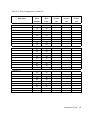
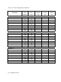
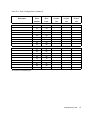
Configuration Forms ............................................................................................65
1.
Introduction
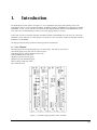
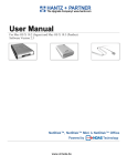
The PCM Paging Control System (see Figure 1-1) is an expandable zone paging and signaling system. The
LUPCMALL consists of 4 pre-assembled modules: PCMTIM, PCMCPU, PCMTBM, and a Zone Paging Module
(PCMZPM). To this, you can add up to two additional Zone Paging Modules (Model: LUPCMZONE, Pec Code
5323-108, Com Code 408186039) to increase system zone paging capacity to 9 zones.
If more than 9 zones are required, expansion assemblies (Model: LUPCMADD, Pec Code 5323-107, Com Code
408186021) can be added up to a total capacity of 99 zones in 3 zone increments. Expansion assemblies include a
PCMCPU and a PCMZPM.
The Paging Control System provides the following features and functions:
1.1. Voice Channel
●
●
●
●
●
●
●
●
Zone Paging & sub zone group paging (up to 32 zone groups, each with up to 99 zones)
Over Ride paging (using loop start or contact closure)
Talk Back paging (centrally-amplified zones only)
Talk/Talk Back selection per zone
High/Low-powered central paging
High/Low power distributed paging
Privacy Beep on talk back zones
Pre-Announce Tone
Figure 1-1: PCMALL Paging System Control Assembly
[5]
1.2. Background Music
• High/Low-Power distributed (buffered for up to 50 amplified speakers)
• High/Low-Powered, using dedicated BGM amplifier
• High/Low-Powered using a single paging/BGM amplifier
• BGM Disable to individual zones
• Local BGM input on each individual zone module
1.3. Signaling Channel
• Night Ringer (90V or contact closure activation)
• Code Calling (2 types - echo & pattern)
• Emergency/Shift Change Tone (tone and duration selectable)
• Specialized modules provide Time-Triggered signaling
1.4. Other Features
• DTMF setting of all operating parameters
• Run/Program switch
• External C-form contacts
• Relay Driver output per zone
• Non-volatile memory for setup data (no backup battery required)
• Setup Tone to assist in volume setting, etc.
• Synchronization to external master clocks
[6]
2.
Before You Start
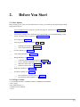
2.1. Select Options
Before setting up your system, use the checklist below to assist you in setting up and programming the PCM
Paging Control System.
____
Type of Telephone Interface (loop start, ground start, page port, station port) (see System Wiring
Connections, Section 5)
____
Total Number of Paging Zones (additional Zone Paging Modules or LUPCMADD Paging Control
System Assemblies may be required) (see Installation, Section 3)
____
Zone Groups (see Section 11.1)
____
Time-Triggered Signaling (see Sections 11.2 and 11.8):
____
____
Signaling Zone Groups (see Section 11.8)
Clock Synchronization (see Section 11.7.1)
____
All-Call Capability (see Section 11.1)
____
Code Calling Capability (see Section 11.2)
____
Background Music (see Section 7):
____
____
____
____
Continuous in Zones Not Being Paged (see Section 7.2)
Cease in All Zones During Page (see Sections 7.3 and 7.4)
Inhibited in Some Zones (see Section 7.6)
Different in Some Zones (see Section 7.5)
____
Night Ring Capability (see Section 5.6)
____
Over Ride Capability (see Section 5.7):
____
____
From Telephone/Loop Start Trunk (see Section 5.2)
From External Audio Equipment (see Appendix A)
2.2. Package Contents
• 4 pre-assembled modules - PCMTIM, PCMCPU, PCMTBM, and PCMZPM
• Power Supply
• Rack Mount brackets (2)
• Installation and Use Manual
• Screws
[7]
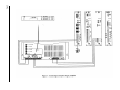
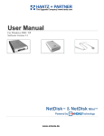
Figure 3-1: Rack Mounting the LUPCMALL Paging Control System
[8]
3.
Installation
3.1. Adding PCMZPM Modules
The LUPCMALL is pre-assembled to accommodate 3 zones of paging. If your installation requires 4 to 9 zones, you
can add one or two Zone Paging Modules (PCMZPM). A total of 3 PCMZPM modules (9 zones total) can be used
on a LUPCMALL assembly. If your installation requires more than 9 zones, you will need one or more
LUPCMADD units to allow system expansion beyond 9 zones. Install the extra PCMZPM modules before mounting
and wiring the PCM System assemblies. (Refer to the LUPCMZONE installation manual).
NOTE: LUPCMADD Paging Control System Expansion Assemblies and Zone Paging Modules can only be added
when the previous assembly contains 3 PCMZPM modules; otherwise, the system will not operate.
3.2. Mounting the PCM System
The Paging Control System Assemblies can be either wall- or rack-mounted.
3.2.1. Wall Mounting
1. After assembling the unit (if necessary) hold the unit level against the surface to which it will be mounted.
2. Mark where the mounting screws should be positioned.
3. Set the assembly aside and install the screws leaving about ¼" of the screw sticking out of the surface.
4. Slip the assembly over these screws and tighten them snuggly.
3.2.2. Rack Mounting
1. Position the left side of the completed PCM assembly (any additional PCMZPM modules should have already
been added) over one of the rack mounting adapters. Refer to Figure 3-1 and use the correct holes for the number of
modules in the assembly (4, 5, or 6 as shown).
2. Secure the left side of the PCM system to the rack adapter using two of the truss head sheet metal screws.
3. Secure the right side of the PCM system to the other rack adapter using the holes for the number of modules in the
assembly and the remaining 2 truss head sheet metal screws.
4. Secure the assembly to a 19" rack (rack screws not supplied).
[9]
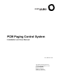
Figure 4-1: LUPCMALL Feature Callouts
[10]
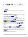
4. LUPCMALL Feature Callouts
Descriptions and Locations
Refer to Figure 4-1.
1. TEL INT SEL Switch Bank - Sets telephone interface type for the TEL LINE jack on the PCMTIM module
(see Section 5).
2. POWER - Indicates that power has been supplied to the module. One exists on each module.
3. TONE VOLUME - Controls the level of all tones produced by the PCM system.
4. BGM SRC VOLUME - Sets background music level for one mode of operation. Used only when an amplifier
without a music input is used as the paging amplifier (see Section 7).
5. NIGHT RING - This RJ11 jack provides connections to the internal night ringer for both 90V analog ring
signals and contact closure activation (see Section 5.6).
6. TEL LINE - Primary paging interface to telephone switch (see Section 5).
7. OVER RIDE - Secondary paging input with higher priority than TEL LINE input. Connects to either loop start
trunk or dry audio signal with contact closure (see Section 5.7).
8. PCMTIM Terminal Strip - Provides connections for background music source (one mode of operation only)
(see Section 7), ground start interface ground (see Section 5.3), and two sets of contact closures that change state
whenever a paging zone is active (see Section 11.11).
9. PCMCPU Terminal Strip - Provides connections to background music audio signals (see Section 7), system
expansion signals (see LUPCMADD manual), EM/SC signal trigger (see Section 9.1), clock resynchronization
(see Section 9.2), and auxiliary power supply input.
10. PCMTBM Terminal Strip - Provides connection to main paging amplifier (see Section 6).
11. PCMZPM Terminal Strip - Provides connections to paging speakers (see Section 8), separate local
background music source (see Section 7) and relay driver outputs (see Section 9.3).
12. OUTPUT Switch - Switch setting determines if PCMZPM module will be compatible with 70V (Hi) speaker
systems or self-amplified speakers (Lo). Locking plate guards against accidental changes in setting.
13. BGM Jumper Field - Jumpers control whether background music is inhibited to a specific zone or all zones
(see Section 7).
14. LPBGM VOLUME - Controls the level of background music in zones using self-amplified speakers. Works
only with system-wide BGM, no effect if local BGM source is used.
[11]
15. TALK BACK Switch Bank - Determines if a 70V speaker zone will operate as a two-way hands-free talk back
zone or as a one-way paging zone (see Section 8.3).
16. TALK BACK DELAY - Controls the amount of delay, after speaking stops, before the system switches to the
listen mode during talk back operation (see Section 8.3).
17. TALK BACK VOLUME - Controls the audio level of the talk back signal (see Section 8.3).
18. NOISE REDUCTION - Enables or disables noise reduction during talk back listening. Mutes listen signal when
audio activity is low (see Section 8.3).
19. DATA LINK - Data com port used to control other module assemblies in the PCM paging system. Uses simple
RCA cables to interconnect units. (see LUPCMADD manual)
20. SYS ID - Switch bank used to set unique address of the PCMCPU module when other LUPCMADD assemblies
are used in the paging system.
21. RUN/PROGRAM Switch - Switch must be set to the PROGRAM position before any system programming can
be done. Return to RUN position for normal system operation. Locking plate ensures that switch will not be
accidentally set to program mode. Switch only needs to be changed on the LUPCMALL main assembly.
LUPCMADD assemblies always stay in RUN mode (see Section 8.1).
22. 12V DC Power Jack - PCM system power supply connects to this jack.
[12]
❑
5.
System Wiring Connections
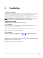
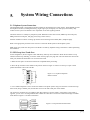
5.1. Telephone System Connections
The PCMTIM module is the telephone interface module for the PCM Paging Control System. The PCMTIM provides
the telephone interface (including talk battery), night ringer input, emergency over ride input, and auxiliary relay
contacts for the system. The module is also responsible for all tone signaling features.
The PCM connects to virtually any telephone system: PBX station lines and CO lines, PBX loop start trunk ports,
PBX ground start trunk ports, and page ports (using contact closure).
Interface installation consists of setting dip switches and connecting with modular (RJ11) telephone plugs.
Refer to the appropriate procedure in this section to connect the PCM System to the telephone system.
Note: In all cases, make sure that power to the PCM is off and any amplifiers being connected to it before performing
the installation.
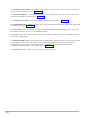
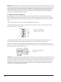
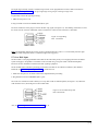
5.2. PBX Loop Start Trunk Port
In this configuration, the unit supplies a 48V talk battery and loop current detection. When the unit detects a loop
resistance between Tip and Ring, it activates. When the loop opens, the page ends. The unit follows the status of the
trunk port; default and VOX timers are not used in this mode.
1. Make sure that power is off and all connections completed before proceeding.
2. Move the dip switches on the module to the position shown in Figure 5-1 below. Use the tip of a pen or other
pointed instrument to move the switches.
Figure 5-1: Loop Start Telephone
Selector Switch
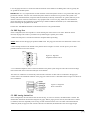
3. Use a modular telephone cord to connect the module to the phone system. Plug one end of the cord into the Loop
Start Trunk (using a modular jack) and the other end in to the TEL LINE jack on the module.
The center two conductors are Tip and Ring (48V DC) and have a specific polarity. If the polarity of the trunk is
opposite, you can use a reversing modular cord to make the connection or reverse the connection through a modular
block. Refer to Figure 5-2 for more information.
Figure 5-2: Loop Start/Ground Start RJ11
[13]
IMPORTANT: The polarity of the Tip & Ring contacts of the RJ11 jack for the Tel Line and Over Ride were chosen
so that when a standard modular cord (one with the tops of both end plugs on the same side of the flat cable) is used
to connect the PCM to a modular wall block, the modular block G (Tip) terminal will be positive with respect to the
R (Ring) terminal. Because of variations in types of modular cords and when stripping a modular cord for direct
connection, always check the polarity of the center conductors or R & G terminals to determine Tip & Ring (the
positive lead is Tip and the negative lead is Ring).
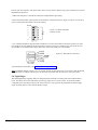
5.3. PBX Ground Start Trunk Port
In this configuration, the unit supplies 48V talk battery and loop current detector. When the ground start trunk
grounds Ring, the unit responds by closing the connection to Tip, which completes the access procedure. When the
loop is opened, the page ends. The unit follows the status of the trunk; default and VOX timers are not used in this
mode.
1. Make sure that power is off and all connection completed before proceeding.
2. Move the dip switches on the module to the position shown in Figure 5-3 below. Use the tip of a pen or other
pointed instrument to move the switches.
Figure 5-3: Ground Start
Telephone Selector Switch
3. Use a modular telephone cord to connect the module to the phone system. Plug one end of the cord into the
Ground Start Trunk (using a modular jack) and the other end in to the TEL LINE jack on the module.
The center two conductors are Tip and Ring (48V DC) and are polarity sensitive. If the polarity of the trunk is
opposite, you can use a reversing modular cord to make the connection or reverse the connection through a modular
block. Refer to Figure 5-4 for more information.
Figure 5-4: Loop Start RJ11
Connections
IMPORTANT: The polarity of the Tip & Ring contacts of the RJ11 jack for the Tel Line and Over Ride were chosen
so that when a standard modular cord (one with the tops of both end plugs on the same side of the flat cable) is used
to connect the PCM to a modular wall block, the modular block G (Tip) terminal will be positive with respect to the
R (Ring) terminal. Because of variations in types of modular cords, and when stripping a modular cord for direct
connection, always check the polarity of the center conductors or R & G terminals to determine Tip & Ring (the
positive lead is Tip and the negative lead is Ring).
[14]
4. Use 24-gauge solid wire to connect the GND ST terminal on the module to the PBX ground. This is typically the
AC ground for the PBX system.
IMPORTANT: It is very important that no other terminals of the PCM system connect to AC ground when using the
ground start interface. Also, the case of the PCM system cannot be connected to AC ground. If the system is not
working and no PCM terminals (except the GND ST terminal) are directly connected to AC ground, there may be an
indirect connection. Check the connections to any equipment with a 3-wire AC plug. Make sure that unbalanced
inputs and outputs of this equipment are isolated using a model LUWMTIA transformer (Corn Code 405891680)
before connecting the equipment to the PCM.
The PA OUT and HPBGM terminals on the PCM do not have to be ground-isolated.
5.4. PBX Page Port
In this configuration, the unit responds to a contact shorting the closure source to its return. When the short is
removed, the page ends. Audio is provided to the system through a separate pair of leads.
1. Make sure that power is off and all connections completed before proceeding.
NOTE: Make sure that the page port produces DTMF tones. The page port must also be hi-directional in order to use
talk back.
2. Move the dip switches on the module to the position shown in Figure 5-5 below. Use the tip of a pen or other
pointed instrument to move the switches.
Figure 5-5: Page Port
Telephone Selector Switch
3. Use a modular telephone cord to connect the module to the phone system. Plug one end of the cord into the Page
Port and the other end in to the TEL LINE jack on the module.
The center two conductors are used for dry audio and the connectors on either side are connected to the page port
contact closure. The maximum resistance of the page port contact closure is 1000 ohms. Refer to Figure 5-6 below for
more information.
Figure 5-6: Page Port
RJ11 Connections
5.5. PBX Analog Station Port
In this configuration, the unit answers after the first full ring. As soon as it answers, the default timer is started. The
default timer determines the maximum length of any page. When a paging zone is selected, the VOX timer is started
(if enabled). This timer repeatedly resets as long as audio is detected on the line. If no audio is detected within the
VOX time period, the page will end. If audio continues to be detected, the default timer will control page length.
[15]
The unit will also respond to CPC pulses (short losses of loop current). When a CPC pulse is detected, the unit will
immediately drop the line.
1. Make sure that power is off and all connections completed before proceeding.
2. Move the TEL INT SEL (dip) switches on the module to the position shown in Figure 5-7 below. Use the tip of
a pen or other pointed instrument to move the switches.
Figure 5-7: Station Telephone
Selector Switch
3. Use a modular telephone cord (minimum 2-conductor) to connect the module to the phone system. The center
two conductors are Tip and Ring and are not polarity sensitive (see Figure 5-8 below). Plug one end of the cord
into the PBX or CO modular jack and the other end in to the TEL LINE jack on the module.
Figure 5-8: Station RJ11 Connections
4. Set Default and VOX timers. See System Programming, Section 11.
Note: The default timeout is factory set to 30 seconds, and the VOX timeout is set to 6 seconds. If both the default
and VOX timers are inhibited, the only way to disconnect the system from the station line is the CPC pulse.
5.6. Night Ringer
The PCM Night Ringer signaling feature is designed to alert personnel to incoming calls after normal business
hours. The feature can be activated either by a 90V ring signal or by a contact closure. In the factory default
configuration, the night ringer sounds in all zones; however, a zone group can be programmed so that the night
ringer can sound only in a user-selected number of zones.
[16]
The night ringer normally sounds a simulated ring tone but can be programmed to sound a chime tone. Refer to
System Programming, Section 11 to set up a night ringer zone group or to change to ringer tone.
To physically connect the night ringer wiring:
1. Make sure that power is off.
2. Plug a modular cord into the NIGHT RING (RJ11) jack.
The center conductors of the plug are used for the 90V ring signal (see Figure 5-9). The flanking conductors are used
for contact closure activation. Maximum contact resistance for contact closure activation is 1000 ohms.
Figure 5-9: Night Ring
RJ11 Connections
Note: The Night Ring feature has priority just above background music. There is a 5-second delay after the night
ring stops before background music is restored (bridges inter-ring pause).
5.7. Over Ride Input
The Over Ride is a non-programmable feature that lets the caller take priority over all paging functions and make a
system-wide page to all speakers. The feature can be activated using a loop start trunk or dedicated telephone.
Provisions are also included to interface with other signaling equipment.
The Over Ride feature includes a quad beep pre-announce tone that can be enabled or inhibited. (The default is
inhibited). See System Programming, Section 11 to enable the tone.
1. Make sure that power is off and all connections completed before proceeding.
2. Plug modular cord into OVER RIDE (RJ-11) jack.
The center two conductors interface directly to a Loop Start Trunk or dedicated phone (see Figure 5-10). When the
trunk becomes active, the PCM goes into Over Ride mode.
Figure 5-10: Over Ride Loop Start
RJ11 Connections
Also, see connecting to an External Audio Source, page 53.
[17]
[18]
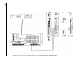
6.
Paging Amplifier Connections
The paging amplifier audio connections are made to the PCMTBM module terminal strip. If the amplifier has a
paging control input, this is connected to the RLY TWO terminals on the PCMTIM module (see Figure 6-1). The
paging amplifier must have a balanced 600-ohm input. The amplifier should be located close to the PCM system
to keep cable lengths reasonably short.
NOTE: To make all audio connections, use 22 AWG shielded, twisted pair on all wire runs. Com Code:
401882956, PEC Code: 2734-SPK.
CAUTION: Make sure the amplifier is turned off or unplugged before wiring.
[19]
[20]
7.
Background Music
The PCM system is very flexible in how it can provide background music throughout the system:
• Background music can be continuously supplied to all zones not being paged. (Requires two amplifiers of the
same power rating.)
• Background music can be supplied by the same amplifier that is supplying paging. (Music input is available on
amplifier.)
• Background music can be supplied by same amplifier that is supplying paging. (No dedicated music input
available on amplifier.)
• Background music or different background music can be supplied to a select group of zones.
• Background music can be supplied to self-amplified (LO-PWR) zones.
• Background music can be inhibited in select groups.
The BGM SRC terminals are used to control background music operations when using a single power amplifier
that does not provide a separate music input. This feature is only used when a single amplifier will be used for both
background music and paging (background music is lost in all zones when a page is made).
NOTE: This input and its associated control is not used when using amplifiers with separate music inputs and
paging control terminals because background music is supplied directly to the amplifier.
7.1. Helpful Hints When Connecting Background Music to the Paging Control System
1. When using the BGMSRC (background music source) input on the PCMTIM as input for background music, the
music is muted to all speakers when any zone is selected. The source input signal is line level.
2. When the HPBGM (high-powered background music) input on the PCMCPU is used, music is muted only in the
zone selected. The source input has to be an amplified signal.
3. When the LPBGM (low power background music) input on the PCMCPU is used as an input for background
music, music is muted only to the zone selected. In this application, either amplified speakers or an amplifier per
zone is used. PCMZPM output power switch is set to LO-PWR. The input background music is line level.
4. When the Local BGM input on the PCMZPM is selected as input for background music, music is muted only to
the zone selected. An amplified signal is required at this input if using 70V speakers.
NOTE: When you want to mute the background music only to the zone in which you are paging, use 2, 3 or 4.
[21]
[22]
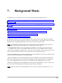
7.2. Background Music Continuously Supplied To All Zones Not Being Paged
See Figure 7-1 on page 20 for connection with a high-powered background music source or Figure 7-2 on page 22
for connection with a low-powered background music source.
NOTE: Requires second amplifier of the same power rating as the paging amplifier.
NOTE: This configuration is not recommended for systems that will use zones with talk back.
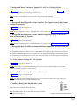
7.3. Background Music Supplied By Same Amplifier That Supplies Paging, Music Input
Available On Amplifier
See Figure 7-4 on page 24 for connections.
NOTE: Requires programming of the 1 Amp BGM feature to be enabled - see System Programming, Section 11
7.4. Background Music Supplied by Same Amplifier Supplying Paging, No Dedicated
Music Input Available On Amplifier
See Figure 7-5 on page 25 for connections.
NOTE: Requires programming of the 1 Amp BGM feature to be enabled - see System Programming, Section 11.
7.5. Background Music Or Different Background Music Supplied To A Select Group Of
Zones
Each PCMZPM module has the ability to have a separate BGM source supply background music to the zones on
that module. PCMZPM modules can be set to operate with 70V speaker and amplifiers or self-amplifed speakers.
The compatible type of background music source (70V for passive speakers or low-level signal for self-amplified
speakers) must be supplied to the module.
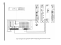
7.5.1. Zone Modules Working With 70V Speakers
See Figure 7-6 on page 26 for connections.
NOTE: You must move both GLOBAL BGM jumpers to the OUT position before making the connections.
Volume is controlled by amplifier’s volume control.
7.5.2. Zone Modules Working With Self-Amplified Speakers
See Figure 7-7 on page 27 for connections.
NOTE: You must move both GLOBAL BGM jumpers to the OUT position before making the connections.
Volume is controlled by the zone module’s LPBGM control.
7.6. Inhibiting Background Music In Select Zones
Background music in any zone can be inhibited by moving both of the zone’s BGM
jumpers from the IN position to the OUT position.
Note: Both BGM jumpers must be moved for the background music
to be inhibited (see Figure 7-3).
Figure 7-3: Background Music Jumpers
[23]
[24]
[25]
[26]
[27]
This page intentionally left blank
[28]
8.
Zone Speaker Wiring and Setup
8.1. Wiring to 70V Speakers
See Figure 8-2 on page 30 for wiring.
NOTE: Make sure PCMZPM OUTPUT switch is set to HI PWR. To set the switch, remove the locking plate, place
switch in desired position, and re-secure the locking plate. The locking plate can be rotated to match the switch
setting.
8.2. Wiring to Self-Amplified Speaker or Dedicated Amplifier
See Figure 8-3 on page 31 for wiring.
NOTE: Make sure PCMZPM OUTPUT switch is set to LO PWR. To set the switch, remove the locking plate, place
switch in desired position, and re-secure the locking plate. The locking plate can be rotated to match the switch
setting.
NOTE: The Tip lead of the self-amplified speaker or dedicated amplifier should be connected to the zone's "+"
(positive) terminal and the Ring lead to the zone's "-" (negative) terminal for proper phasing.
8.3. Setting a Zone for Talk Back Operation
Any zone of 70V speakers can be made into a talk back zone that provides hands-free two-way communications
between the zone and the telephone. The Talk back switches at the top of the PCMZPM module (see Figure 8-1) set
the operation mode. During all-call and group zone pages, talk back is inhibited. Talk back operation is not available
in zone modules that are set for LO PWR operation.
Talk back is not advisable in zones that have more than 4 speakers or where the environment is very noisy since both
reduce the clarity of the talk back signal.
Using a second amplifier to provide background music to all zones not being paged is not recommended when talk
back is being used. Bleed through of the background music signal onto the talk back signal can be significant
depending on system wiring.
Use the TALK BACK DELAY and TALK BACK VOLUME controls to adjust for smooth two-way conversations.
NOISE REDUCTION can be set to ON to mute listen background noise when audio activity is low.
ZONE A
ZONE B
ZONE C
Figure 8-1: Talk Back Switches
OFF
ON
TALKBACK
[29]
Figure 8-2: Zone Wiring to Speakers
[30]
[31]
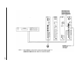
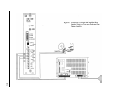
Figure 9-1: Connection of Relays to the Relay Driver Outputs
[32]
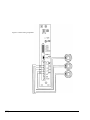
9.
Optional Wiring
9.1. CPU to Emergency Signaling
External input control is available to trigger a tone signal from the PCM over the paging system. Shorting EM/SC to
the GND terminal will produce a user-programmed tone into a specific zone group.
This feature is typically used to signal shift changes using a contact closure pair from an external master clock. The
tone signal can be directed to a specific group of zones by programming them into the EM/SC zone group.
The length and type of tone can also be programmed as well. A Follow Contact programming option allows the tone
to be emitted for as long as the external contacts remain closed.
See System Programming, Section 11 for information on programming the EM/SC feature.
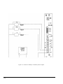
9.2. CPU to Re-Synch (Master Clock)
The PCM system contains a real time clock that is used to control the trigger for up to 8 separate "Time Tones". In
order to ensure that the PCM will remain in sync with external master clocks, a Re-Synchronization feature is
provided.
Shorting the AUX and GND terminals together will reset the real time clock to a predetermined time. By
programming this time so that it coincides with the time of a master clock contact closure, the PCM will be resynchronized with the master clock.
The time of day of the re-synchronization must first be programmed into the PCM and the feature enabled for this
feature to work. See System Programming, Section 11 for further information on this function.
9.3. Relay Drivers
Each zone module has three relay driver output terminals - RD A, RD B, and RD C - one for each speaker zone.
When a zone is active, its associated relay driver is shorted to the RD COM terminal through an open collector
transistor (see Figure 9-1). These drivers can be used to activate external equipment or relays.
IMPORTANT: These outputs are not contact closures and have specific voltage and current requirements. The power
supply for these relays must be 12V DC or less. The total sink current per driver cannot exceed 100mA.
NOTE: Some power supplies are rated at 12V DC, but when lightly loaded, are considerably higher in output
voltage. If the power supply for the relay has an unloaded output of greater than 13V DC, the relay drivers may begin
to conduct, thereby energizing the relay. If this problem occurs, you can either replace the supply with a regulated
supply, or use a lower voltage supply.
[33]
This page intentionally left blank
[34]
10.
Power-Up of PCM and
Associated Equipment
10.1. Power-Up Sequence
All equipment in the paging system should remain off until the system wiring is completed. This is the recommended
power-up sequence of the paging equipment after initial wiring:
1. Double check that all PCMZPM modules are set for the correct type of operation - HI PWR for 70V speakers or
LO PWR for self-amplified speakers and dedicated amplifiers.
2. Turn all system volume controls to minimum.
3. Connect the power supply coaxial connector to the jack on the PCMCPU module and plug the power supply into a
110V AC wall outlet.
4. Power up all power amplifiers and self-amplified speakers.
5. Power up background music sources.
6. Power up other external devices.
7. Adjust all volume controls to desired levels.
10.2. Priority Order
The following is a list of the priority operation of the PCM Zone Paging System.
1. Over Ride (Highest)
2. Emergency/Shift Change (EM/SC)
3. Time Triggers
4. Voice Page/Code Call
5. Night Ring
6. Background Music (Lowest)
[35]
This page intentionally left blank
[36]
11.
System Programming
System programming lets you set certain PCM options and tone features using the DTMF keys of a telephone. It
also lets you to program paging zone groups and signaling zone groups.
All programming is accomplished through the TEL LINE jack on the PCMTIM module regardless of the
telephone interface used.
NOTE: To simplify initial programming, it is recommended that you use Loop Start Trunk configuration with a
single line 2500-type telephone or your Test Set connected to the TEL LINE input. You do not need to program
the system to access zones. The system is ready from the factory to access individual zones and All-Call.
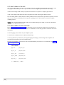
To program the PCM system, follow these instructions:
PCM
CPU
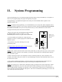
1. Remove the switch lock on the PCMCPU module and place
the PROGRAM/RUN switch (see Figure 11-1) to the
PROGRAM position (down). The green LED will illuminate.
S1
S2
S3
S4
2. Access the PCM system (either use a single 2500-type
telephone or Test Set, or dial the paging access number from the
telephone system).
3. You will hear 3 beep tones indicating access to the
programming mode.
4. Dial the Feature Code for the option you wish to program.
(See Feature Codes and Defaults, Section 12).
Press the [#] key after you enter a Feature Code.
0
SYS
ID
1
Figure 11-1:
Run Program
Switch
POWER
RUN
PROGRAM
SWITCH
LOCKING
PLATE
DATA
LINK
NOTE: After you have entered a Feature Code (and any other data), you must press the [#] key to enter it into the
system. If the system accepts the code (and data), you will hear a short double beep confirming that the data has
been stored in the system.
Continue with the next Feature Code immediately after the confirming double beep. If the information is not
accepted, you will hear a busy tone. In this case, you should hang up, check the code and the data, then re-access
the system and try again.
5. Once you have finished programming, you must first hang up the programming phone and then place the
Program/Run switch in the Run position. The green LED will go out. Replace the switch lock.
NOTE: The system uses a 1 minute timer to determine a hang up in station access mode. If more than 1 minute
elapses between DTMF tones, the system will assume that the caller has hung up. This also means that if you
make a mistake and have to hang up, you will have to wait 1 minute before retrying. One way to shorten this is to
remove the plug from the TEL LINE jack and replace it. This forces an immediate system hang up (of course, this
only works if you are near the system).
[37]
11.1. Programming Paging Zone Groups
32 paging zone groups can be created. Each zone group can consist of up to 99 zones. To create a zone group:
1. Dial [*] followed by 2-digit number of zone group (01 - 32) you want to create. Follow this with the 2-digit
number of the zones you want to include in the zone group.
Example: If you want to create zone group 7 consisting of zones 2, 3, and 12, you would dial:
[*] [0] [7] [0] [2] [0] [3] [1] [2] [#]
NOTE: When finished, save the zone group data into memory by pressing [#].
2. Repeat the above procedure to program additional zone groups.
11.1.1. To Erase A Zone Paging or Signaling Group
Press [*] and the 2-digit zone group number, then press [#]. Once done, any attempt to call the zone group will
produce a busy tone.
11.2. Programming Signaling Zone Groups
Use the following procedure to create the signaling zone groups (Emergency/Shift Change, Night Ring, Code Call).
1. Dial the Feature Code for the zone group you wish to create ([*] [9] [2] for EM/SC, [*] [9] [3] for Night Ring, or
[*] [9] [4] for Code Call).
Then dial the 2-digit numbers of the zones you want to be in the zone group.
Example: If you want to create the EM/SC zone group consisting of zones 2, 3, and 12, you would dial:
[*] [9] [2] [0] [2] [0] [3] [1] [2] [#]
NOTE: When finished, save the zone group data into memory by pressing [#].
2. Repeat the above procedure to program additional zone groups.
11.3. Interface Default Timer
If the PCM system is connected to a PBX station port, you can set the maximum page duration (default timer). The
factory default for this timer is 30 seconds. If you wish to inhibit the default timer, enter the Feature Code followed
by "00". To change the time, enter the Feature Code and the new 2-digit number corresponding to the time desired.
The 2-digit number represents 10s of seconds (see Note 3 in Notes to Feature Codes on page 44).
11.4. Interface VOX Timer
If the PCM system is connected to a station port, you can set the default timer for the VOX time out. The default
value is 6 seconds. To inhibit the timer, enter the Feature Code followed by "0". To change the time, enter the
Feature Code followed by a single digit from 1 to 9, corresponding to 1 to 9 seconds.
11.5. Dialing Timeout
When the dialing timeout is enabled, the user must dial a DTMF digit within 15 seconds of the last digit or else the
system will produce an error tone. The user will then have to hang up and access the system again. In station access
mode, the PCM will drop the line after 5 seconds of error tone. This will free the paging system for another page
access.
[38]
11.6. Single Amp BGM Enable
Single amplifier BGM operation lets the PCM use the paging amplifier to provide high-powered BGM to passive
speakers when the paging system is idle. When this option is enabled, the BGM SRC terminals are connected to the
paging amplifier's input and HPBGM bus is connected to the paging amplifier's output. As soon as the PCM System
becomes active, the BGM SRC and HPBGM connections to the paging amplifier are removed and the amplifier is
ready for paging. When a page or tone signal is in progress, BGM is lost in all passive speaker zones not being paged.
The 1-amp BGM option must be inhibited when a second amplifier is used to supply the high-powered BGM.
11.7. Programming the Real Time Clock
A built-in real time clock keeps track of time when using the signaling functions of the PCMTBM module. See the
Feature Codes Chart (pages 41-44) for the code required to set the clock. Refer to the chart below and enter time in
24:00 hour format.
The real time clock in the PCMTBM module must be set to the current time of day for proper operation. Time must
be entered in 24:00 hour format.
24:00 Hour Time Chart
00:00 - Midnight
01:00 - 1 am
02:00 - 2 am
03:00 - 3 am
04:00 - 4 am
05:00 - 5 am
06:00 - 6 am
07:00 - 7 am
08:00 - 8 am
09:00 - 9 am
10:00 - 10 am
11:00 - 11 am
12:00 - Noon
13:00 - 1 pm
14:00 - 2 pm
15:00 - 3 pm
16:00 - 4 pm
17:00 - 5 pm
18:00 - 6 pm
19:00 - 7 pm
20:00 - 8 pm
21:00 - 9 pm
22:00 - 10 pm
23:00 - 11 pm
11.7.1. Clock Synchronization
An option is available to synchronize the PCM's real time clock to an external reference clock. The reference clock
must provide a contact closure at a particular time of day. Using the clock synchronization code, the PCM is
programmed for that same time of day. When the reference clock closes the contacts, the real time clock in the PCM
will reset itself to the programmed time of day. The clock synchronization function works independently of the clock
set function. This function can be inhibited to prevent accidental resetting of the real time clock.
11.8. Time-Triggered Events
The real time clock in the PCMTBM module gives the ability to have up to eight time-triggered tone events. They
can be used to signal breaks and shift changes throughout the day. Time-triggered events will sound at the same time
every day of the week. Each time trigger has its own zone group and tone selection. Time-triggered tones can also be
inhibited and enabled without changing any of the previously programmed data.
11.9. Setup Tone
The setup tone is available to assist in the adjustment of speaker volume. The setup tone is only available in the
programming mode. To activate the setup tone, dial 000 and hang up to deactivate the tone.
11.10. Reset Default Values
A Feature Code is available to reset the PCM system to the original factory default values. Note: All zone groups are
also reset. This process takes 5 - 10 seconds. Wait for confirmation tone before hanging up.
[39]
11.11. Relay Contacts
The PCM system provides a set of dual "C-form" contacts which can be used to activate external equipment. The
relay contacts are rated at 2A @ 30V DC/0.6A @ 120V AC (resistive). The relay changes state whenever a zone
is active, and stays in this state until the zone page is completed.
[40]
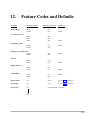
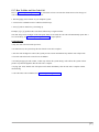
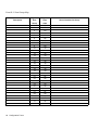
12.
Feature Codes and Defaults
FEATURE
FEATURE CODE
ADDITIONAL DATA
DEFAULT
Privacy Beep
Inhibit
Enable
006
007
Enable
Inhibit
Beep
Chime
003
004
005
Chime
Inhibit
Enable
001
002
Inhibit
Emergency Over Ride Tone
Inhibit
Enable
008
009
Inhibit
Pre-Announce Tone
Confirmation Tone
All-Call
Inhibit
Enable
010
011
Enable
Inhibit
Enable
012
013
Enable
Inhibit
Enable
018
019
Inhibit
Default Timer
050
00-99
03 (See note on page 44)
VOX Timer
051
0-9
6 (See note on page 44)
Zone Group
*01
Dialing Time-out
1-Amp BGM
Zones Numbers No Zones
*32
[41]
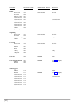
FEATURE
FEATURE CODE
ADDITIONAL DATA
DEFAULT
Zone Group
No Tone
Follow Contact
2-Second Tone
3-Second Tone
4-Second Tone
5-Second Tone
6-Second Tone
7-Second Tone
Chime
Quad Beep
*92
020
021
022
023
024
025
026
027
028
029
Zone Numbers
All Call
Night Ring
Zone Group
No Tone
Simulated Ring
Chime
*93
030
031
032
Zone Numbers
Code Call
Zone Group
Inhibit
Pattern
Echo
1 Play
1 Repeat
2 Repeat
*94
040
041
042
043
044
045
Zone Numbers
Clock Set
060
HHMM
00:00
Clock Synchronization
Inhibit
Enable
067
068
069
HHMM
See Note (page 44)
Inhibit
Time Trigger 1
Zone Group
Inhibit
Enable
2-Second Tone
3-Second Tone
4-Second Tone
5-Second Tone
6-Second Tone
7-Second Tone
8-Second Tone
Chime
*81
110
111
112
113
114
115
116
117
118
119
Zone Numbers
No Zones
Inhibit
See Note (page 44)
EM/SC
[42]
3-Second Tone
All-Call
Ring
All-Call
Inhibit
1 Play
HHMM
3-Second Tone
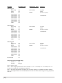
FEATURE
FEATURE CODE
ADDITIONAL DATA
DEFAULT
Time Trigger 2
Zone Group
Inhibit
Enable
2-Second Tone
3-Second Tone
4-Second Tone
5-Second Tone
6-Second Tone
7-Second Tone
8-Second Tone
Chime
*82
120
121
122
123
124
125
126
127
128
129
Zone Numbers
No Zones
Inhibit
See Note (page 44)
Time Trigger 3
Zone Group
Inhibit
Enable
2-Second Tone
3-Second Tone
4-Second Tone
5-Second Tone
6-Second Tone
7-Second Tone
8-Second Tone
Chime
*83
130
131
132
133
134
135
136
137
138
139
Zone Numbers
Time Trigger 4
Zone Group
Inhibit
Enable
2-Second Tone
3-Second Tone
4-Second Tone
5-Second Tone
6-Second Tone
7-Second Tone
8-Second Tone
Chime
*84
140
141
142
143
144
145
146
147
148
149
Time Trigger 5
Zone Group
Inhibit
Enable
2-Second Tone
3-Second Tone
4-Second Tone
5-Second Tone
6-Second Tone
7-Second Tone
8-Second Tone
Chime
*85
150
151
152
153
154
155
156
157
158
159
HHMM
3-Second Tone
HHMM
No Zones
Inhibit
See Note (page 44)
3-Second Tone
Zone Numbers
HHMM
No Zones
Inhibit
See Note (page 44)
3-Second Tone
Zone Numbers
HHMM
No Zones
Inhibit
See Note (page 44)
3-Second Tone
[43]
FEATURE
FEATURE CODE
ADDITIONAL DATA
DEFAULT
Time Trigger 6
Zone Group
Inhibit
Enable
2-Second Tone
3-Second Tone
4-Second Tone
5-Second Tone
6-Second Tone
7-Second Tone
8-Second Tone
Chime
*86
160
161
162
163
164
165
166
167
168
169
Zone Numbers
No Zones
Inhibit
See Note 3 (below)
Time Trigger 7
Zone Group
Inhibit
Enable
2-Second Tone
3-Second Tone
4-Second Tone
5-Second Tone
6-Second Tone
7-Second Tone
8-Second Tone
Chime
*87
170
171
172
173
174
175
176
177
178
179
Zone Numbers
Time Trigger 8
Zone Group
Inhibit
Enable
2-Second Tone
3-Second Tone
4-Second Tone
5-Second Tone
6-Second Tone
7-Second Tone
8-Second Tone
Chime
*88
180
181
182
183
184
185
186
187
188
189
Reset Default
999
HHMM
3-Second Tone
HHMM
No Zones
Inhibit
See Note 3 (below)
3-Second Tone
Zone Numbers
HHMM
No Zones
Inhibit
See Note 3 (below)
3-Second Tone
Setup Tone (in Program Mode Only)
Turn On
000
Turn Off
Hang Up
Notes to Feature Codes:
Note 1. These 2 digits represent time in 10s of seconds, i.e., "01" = 10 seconds, "03" = 30 seconds, "09" = 90
seconds, etc. Entering "00" will inhibit timer operation.
Note 2. This single digit indicates VOX delay time in seconds. Entering "0" will inhibit VOX timer operation.
Note 3. Entering the Feature Code without additional time data will enable feature using previously programmed
time data.
[44]
13.
Paging: How To Use The
PCM
13.1. Paging Zones
The PCM system supports from 3 to 99 different paging zones (in groups of 3). It also supports up to 32 paging
zone groups for voice paging application, and 11 zone groups for signalling applications (night ring, code call,
EM/SC, 8 time triggers). Each zone group consists of 1 to 99 (user-programmed) zones. Paging zone groups are
accessible by dialing a specific zone group number through the telephone. Signaling zone groups are automatically
activated by the system.
Each individual paging zone can be either of two types, one-way paging or two-way talk back (talk back requires
PCMTBM module and is operable only in central-amplified zones). Talk back is not available to zone groups.
Refer to System Programming, Section 11, for instructions on how to program zones and zone groups.
13.2. How To Page Zones
1. Dial the paging access number for your telephone system.
2. Listen for the confirmation tone if enabled (a double beep).
3. Dial the number of the zone you wish to page. All dialing must be two (2) digits, i.e., [0] [1] for zone 1, [0] [2]
for zone 2, etc., through [0] [9] for zone 9, then up to [9] [9] for zone 99. If a zone number does not exist, the
caller will hear a busy tone.
4. Make the page and hang up when finished.
13.3. How To Make An All-Call Page
1. Dial the paging access number for your telephone system.
2. Listen for the confirmation tone if enabled (double beep).
3. Dial [0] [0], make the All-Call page, and hang up when finished.
Note: See System Programming, Section 11, to disable All-Call.
13.4. How To Page A Zone Group
1. Dial the paging access number for your telephone system.
2. Listen for the confirmation tone if enabled (a double beep).
3. Dial [*] and the zone group number you wish to page. Zone group numbers consist of 2 digits.
Example: Dial: [*] [0] [1] for zone group 1, [*] [0] [2] for zone group 2, etc., through [*] [0] [9] for zone group 9,
then up to [*] [3] [2] for zone group 32 (maximum number of zone groups). Dialing numbers above 32 or dialing
a zone group that does not exist, will result in a busy signal.
NOTE: Talk Back is not available in zone group paging.
[45]
13.5. How To Make A Code Call
Code calling is the ability to activate a series of chime tones over a signalling zone group (the specific zones in the
zone group are determined by the user - up to 99 zones). The PCM supports pattern and echo code calling.
• Pattern Code Calling sounds a factory-set pattern of chime tones in response to a single keypad selection.
• Echo Code Calling sounds chime tones that correspond to the actual 2-digit keypad numbers entered.
The code calling feature is deactivated as the factory default. An auto repeat feature is provided to repeat the code call
once or twice with a 5-second delay between repeats. No paging access is allowed until a code call is complete
(including repeats).
NOTE: The voice paging function of the PCM system is inhibited during code calling. A code call is discarded if
interrupted by a higher priority function.
13.6. How To Make A Pattern Code Call
Refer to System Programming, Section 11, for instructions on how to activate this feature and to select the type of
code call, and/or activate the auto repeat feature. (As a minimum, the code call type must be selected in order to use
this feature.)
1. Dial the paging access number for your telephone system.
2. Listen for the confirmation tone if enabled (a double beep).
3. Press [#] followed by a number key from [0] through [9], then hang up. The resulting code call pattern will
correspond to the number in the Code Call Table below.
If the auto repeat feature is activated, the code call will automatically repeat after a five-second delay. (See System
Programming, Section 11.)
Code Call Table
[0] = CC
[5] = CC_CC
[1] = C_C
[6] = CC_CCC
[2] = C_CC
[7] = CCC_C
[3] = C_CCC
[8] = CCC_CC
[4] = CC_C
[9] = CCC_CCC
C = Chime tone, _ = pause.
[46]
13.7. How To Make An Echo Code Call
Refer to System Programming, Section 11, for instructions on how to activate this feature and to select the type of
code call, and/or activate the auto repeat feature.
1. Dial the paging access number for your telephone system.
2. Listen for the confirmation tone if enabled (a double beep).
3. Press [#] and two number keys, then hang up.
Example: [#] [3] [1] produces three tone bursts followed by a single tone burst.
You must always enter two digits. If the auto repeat feature is activated, the code call will automatically repeat after a
five-second delay. See System Programming, Section 11, for repeat options.
Code Call Notes:
• Only one code call can be made per access.
• On station access, the system drops the line after the code call is complete.
• After the code call digits are entered, the system provides a short confirmation beep and the code call proceeds.
• The caller will not hear the code call over the handset.
• On trunk port/page port with contact, a caller may call into the system during a code call but the system will not
produce any acknowledgement until the code call is complete.
• On page port VOX, another code call request can be made immediately after the code call is complete without
disconnecting.
• Code call feature can be inhibited. See System Programming, Section 11.
[47]
This page intentionally left blank
[48]
14.
Testing and Troubleshooting
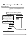
Functional Test Guide
Use the following chart to verify proper operation after installation. To start the test,
pick up a telephone and dial the access code for the port to which the PCM is
connected.
Does the PCM activate?
The PCM is activated if it returns a confirmation tone over the telephone.
NO
Check List
1. Double check for correct wiring to PCMTIM.
2. Ensure connections are making proper contact.
3. Check power supply. (Be sure all LEDs are lit on each
module.)
4. Make sure that PCMTIM dip switch settings correspond
to the type of tele input being used, loop start, etc...
YES
Is paging possible?
Press [00] on telephone
YES
NO
DONE
Does the PCM return a confirmation tone?
NO
YES
Is paging possible?
Press [00] on telephone
YES
NO
DONE
Follow Procedure B to determine if an audio
path can be established through the PCM.
Follow Procedure A to determine if the PCM is
functional.
[49]
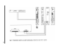
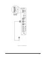
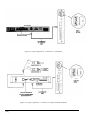
Procedure A
Refer to Figure 14-1 on page 51.
1. Disconnect PCM from the telephone system.
2. Set dip Switch 3, 4, and 5 to ON and 1, 2, 6, and 7 to OFF on the PCMTIM.
3. Connect a telephone test set/2500-type telephone to the TEL line input of the PCMTIM.
4. Go off hook with the test set/2500-type telephone.
5a. If confirmation tone is heard and a page can be made, the PCM telephone interface is working correctly. Go to
Procedure B.
If confirmation tone is not heard, check the wiring from the telephone system or check the port that has been
provided by the telephone system to ensure you have the dip switches set appropriately for that port.
See Section 5 for proper dip switch settings.
5b. If the settings and wiring are correct and the PCM still does not page, call Technical Support.
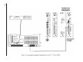
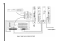
Procedure B
Refer to Figure 14-2 on page 52.
1. Access the PCM and press [00] on the paging telephone. Simulate a page by talking into the paging telephone.
2. While talking, monitor with a test set on the PCMTBM at PA IN & RT. If voice is heard, monitor with a test set on
the PCMTBM PA OUT & RT. If the voice is heard on the PA IN & RT and not on the PA OUT & RT, ensure the
amplifier’s input level control is turned up. If the input is turned up on the amplifier but you still have no voice on
the PCMTBM PA OUT & RT terminals, the amplifier may be defective. Call Technical Support to verify this.
3. If the voice is heard on both PA IN & RT and PA OUT & RT, then monitor the PCMZPM zone outputs. Ensure
that the PCMZPM Lo/Hi Power switch is in the Hi Power mode. If you are in the Lo Power mode and using external
amplifiers per zone, voice should be heard on the zone output. If it is heard, monitor each zone amplifier’s input, then
monitor the output of each amplifier. If the amplifier has no output, check the input level control of each amplifier.
Make sure it is turned up. If you still have no output, contact Technical Support.
[50]
Figure 14-1: Test Procedure A.
[51]
[52]
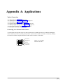
Appendix A: Applications
Typical Connections
* To Slave Amps (see Figure A-2 on page 54)
* To Ambient Level Controller (see Figure A-3 on page 55)
* To Call Stacker (see Figure A-4 on page 56)
* To Digital Feedback Eliminator (see Figure A-5 on page 56)
* To Multiple Digital Message Unit (see Figure A-6 on page 57)
* To Operate Door Speakers (see Figure A-7 on page 58)
* Connecting to an External Audio Source (see below)
Connecting to an External Audio Source
A contact closure and dry audio source can also be used for the Over Ride input. The two conductors flanking the
center conductors provide a dry audio gateway into the system-wide Over Ride. Over Ride is activated by shorting
the outermost conductors together. Maximum contact closure resistance is 1000 ohms.
6 - Closure Return
5 - Dry Audio (return)
4 - Not used
Figure A-1: Over Ride
External Audio RJ11
3 - Not used
2 - Dry Audio (hot)
1 - Closure Source
TEL LINE
[53]
[54]
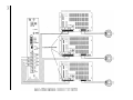
Figure A-3: Typical Application - Connecting to an Ambient Level Controller
[55]
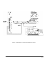
Figure A-4: Typical Application - Connection to a Call Stacker
Figure A-5: Typical Application - Connection to a Digital Feedback Eliminator
[56]
[57]
[58]
Appendix B: Tones
Confirmation Tone - A double-beep tone heard by the caller after dialing the paging access number and before
entering the desired zone number. The default for the tone is enabled. The tone can also be inhibited. See System
Programming, Section 11, if you wish to inhibit this tone.
Emergency/Shift Change (EM/SC) Tone - This tone is activated when the EM/SC terminal on the PCMCPU
module is shorted to the GND terminal. (Refer to the instructions included with the PCMCPU module for wiring.)
This tone has the second highest priority after Over Ride. Tone options available are: no tone, a 2 - 7 second tone
blast (3 seconds is default), a tone that follows the contact closure, a chime tone, or a quad beep. See System
Programming, Section 11, to change the tone.
Over Ride Tone - This tone is produced when this higest priority feature is activated. It produces a quad beep preannounce tone that can be enabled or inhibited. (The default is inhibited). See System Programming, Section 11, to
enable the tone.
Pre-Announce Tone - This tone is heard at the speakers being paged and at the telephone. It is either a chime
(default) or beep. The pre-announce tone can also be inhibited. See System Programming, Section 11, to change or
inhibit this tone.
Privacy Beep - This short (100msec.) tone is produced every 15 seconds into active talk back zones. The default
for this tone is enabled. The tone can also be inhibited. See System Programming, Section 11, if you wish to
inhibit this tone.
Setup Tone - This tone can be activated only when the PCM system is in Program mode (set with Run/Program
switch on PCMCPU module). It is a system-wide interrupted tone which can be used by the installer to check
speaker operation, set operational level of speaker zones, balance zones, etc.
Time-Triggered Tone - The PCMTBM contains a real-time clock and a time-trigger feature that provides up to
eight (8) time-triggered tones over separate signaling zone groups. The tone choices are: no tone, a 1 - 8 second
tone blast (3-second blast is the default), or a chime tone. See System Programming, Section 11, to set this feature.
NOTE: The volume level of all of the above tones are controlled by the TONE VOLUME control on the
PCMTIM. All tones are at the same level. Clockwise rotation of the control increases the level. Counterclockwise
rotation of the control decreases the level.
[59]
This page intentionally left blank
[60]
Appendix C: Glossary of
Programmable Features
1-Amp BGM: Enabling this feature allows a single amp to provide background music (BGM) and paging
throughout the system (BGM is lost in all zones during a zone page). This feature must be disabled when using a
separate BGM amplifier and a paging amplifier.
All-Call: System-wide all-call announcements made by dialing 00 can be inhibited.
Clock Set: The real time clock in the PCM is set using a 24-hour time format with this feature.
Clock Synchronization: Closing the AUX and GND terminals on the PCMCPU will reset the real time clock to
whatever time has been programmed in this feature. Both the time must be set and the feature enabled to use this
feature. Setting the time does not automatically enable the feature. Likewise, inhibiting the feature does not erase
the time setting.
Code Call: The PCM has the ability to produce chime code calls into a specific zone group. The zones in the
group, type of code call (using pre-programmed patterns or chiming in response to the digits dialed), and number
of plays of the code are programmable.
Confirmation Tone: Two short tone bursts heard only in the handset to indicate entry to the zone paging system.
Default Timer: The default timer determines the maximum time a page is in the station access mode. The timer is
programmable in 10 second increments up to 990 seconds ("99"). The timer can also be inhibited by using "00" as
the time length code.
Dialing Time Out: A 15-second dialing timeout is provided to prevent accidental lockouts. This time out can be
inhibited.
Emergency Over Ride Tone: A quick 4-tone burst that proceeds over ride announcements can be selected.
EM/SC Emergency/Shift Tone: This is an external contact closure triggered tone burst into a specific zone group.
The specific zones in the group, the length of the tone burst, or the type of tone can be programmed.
Night Ring: When activated by either a 90V ring signal or contact closure, the night ring tone sounds into a
specific zone group. The zone group and type of tone can be programmed.
Pre-Announce Tone: Short tone heard in the zone being paged at the start of the page.
Privacy Beep: A short beep heard every 15 seconds during a conversation with a talk back zone to discourage
eavesdropping.
Reset Defaults: Resets all programming features to original factory defaults.
Setup Tone: Used by the installer to check the operation of the speaker and amplifier system. Produces a systemwide beep tone to provide an operational check of the paging system. This is only available when the
RUN/PROGRAM switch is in the RUN position and the programming phone is off hook. Hanging up stops the
tone.
[61]
Time Triggers (1-8): Eight separate time-triggered tones can be programmed into the PCM. A specific zone group
can be programmed for each time-triggered tone, the time of the trigger, as well as the length or type of tone. Time
tones can be inhibited and re-enabled without losing previously set trigger times.
VOX Timer: The length of a silence interval before the PCM disconnects the page in station mode is set by this
feature. It can be set in 1 second increments from 1-9 seconds. Setting the time length to 0 will inhibit the timer.
Zone Groups: The PCM system allows zones to be grouped and accessed as one. Up to 32 zone groups can be
created, each with up to 99 individual zones in each. Zone group programming sets these groups.
[62]
Appendix D: Configuration Forms
* Zone Configuration (Form D-1 on page 64)
* Zone Group Map (Form D-2 on page 68)
[63]
Form D-1: Zone Configuration
Description
Physical
Physical
Music
Talk Back
Night Ring
Zone
Zone
in Zone
in Zone
in Zone
Number
Code
Y/N
Y/N
Y/N
1
1
2
2
3
3
4
4
5
5
6
6
7
7
8
8
9
9
10
10
11
11
12
12
13
13
14
14
15
15
16
16
17
17
18
18
19
19
20
20
21
21
22
22
23
23
24
24
25
25
26
26
27
27
Expansion 1
Expansion 2
64 Configuration Forms
Form D-1: Zone Configuration (Continued)
Description
Physical
Physical
Music
Talk Back
Night Ring
Zone
Zone
in Zone
in Zone
in Zone
Number
Code
Y/N
Y/N
Y/N
28
28
29
29
30
30
31
31
32
32
33
33
34
34
35
35
36
36
37
37
38
38
39
39
40
40
41
41
42
42
43
43
44
44
45
45
46
46
47
47
48
48
49
49
50
50
51
51
52
52
53
53
54
54
Expansion 3
Expansion 4
Expansion 5
Configuration Forms
65
Form D-1: Zone Configuration (Continued)
Description
Physical
Physical
Music
Talk Back
Night Ring
Zone
Zone
in Zone
in Zone
in Zone
Number
Code
Y/N
Y/N
Y/N
55
55
56
56
57
57
58
58
59
59
60
60
61
61
62
62
63
63
64
64
65
65
66
66
67
67
68
68
69
69
70
70
71
71
72
72
73
73
74
74
75
75
76
76
77
77
78
78
79
79
80
80
81
81
Expansion 6
Expansion 7
Expansion 8
66 Configuration Forms
Form D-1: Zone Configuration (Continued)
Description
Physical
Physical
Music
Talk Back
Night Ring
Zone
Zone
in Zone
in Zone
in Zone
Number
Code
Y/N
Y/N
Y/N
82
82
83
83
84
84
85
85
86
86
87
87
88
88
89
89
90
90
91
91
92
92
93
93
94
94
95
95
96
96
97
97
98
98
99
99
Expansion 9
Expansion 10
All Zones are accessed by 00
Configuration Forms
67
From D-2. Zone Groups Map
Description
68 Configuration Forms
Physical
Physical
Zone
Zone
Group
Code
1
*01
2
*02
3
*03
4
*04
5
*05
6
*06
7
*07
8
*08
9
*09
10
*10
11
*11
12
*12
13
*13
14
*14
15
*15
16
*16
17
*17
18
*18
19
*19
20
*20
21
*21
22
*22
23
*23
24
*24
25
*25
26
*26
27
*27
28
*28
29
*29
30
*30
31
*31
32
*32
Zones Contained In Group