1
®
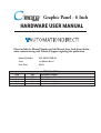
6-inch Micro-Graphic Panel
Hardware User Manual
EA1-MG6-USER-M
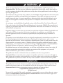
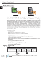
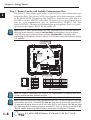
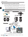
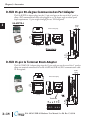
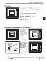
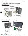
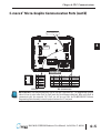
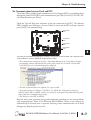
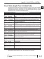
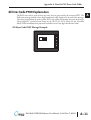
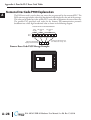
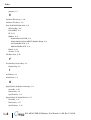
C-more 6” Micro-Graphic Panel
EA1-S6ML - shown in Portrait Mode
C-more 6” Micro-Graphic Panel
EA1-S6MLW - shown in Landscape Mode
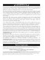
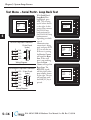
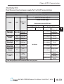
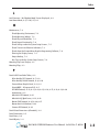
C-more 6” Micro-Graphic Panel Installed in a
21-button Portrait Keypad Bezel EA-MG6-BZ2P
C-more 6” Micro-Graphic Panel Installed in a
20-button Landscape Keypad Bezel EA-MG6-BZ2
®
Graphic Panel - 6 Inch
HARDWARE USER MANUAL
Please include the Manual Number and the Manual Issue, both shown below,
when communicating with Technical Support regarding this publication.
Manual Number:
EA1-MG6-USER-M
Issue:
1st Edition Rev C.
Issue Date:
09/10
Publication History
Issue
Date
Description of Changes
1st Edition
Rev. A
Rev. B
Rev. C
07/08
10/08
10/08
09/10
Original issue
Added CLICK PLC.
Added Mitsubishi Q / QnA
Added Allen Bradley PLC DF1 imformation and made minor corrections
WARNING Thank you for purchasing automation equipment from Automationdirect.com®, doing business as,
AutomationDirect. We want your new automation equipment to operate safely. Anyone who installs or
uses this equipment should read this publication (and any other relevant publications) before installing or
operating the equipment.
To minimize the risk of potential safety problems, you should follow all applicable local and national codes
that regulate the installation and operation of your equipment. These codes vary from area to area and
usually change with time. It is your responsibility to determine which codes should be followed, and to
verify that the equipment, installation, and operation is in compliance with the latest revision of these
codes.
At a minimum, you should follow all applicable sections of the National Fire Code, National Electrical
Code, and the codes of the National Electrical Manufacturer's Association (NEMA). There may be local
regulatory or government offices that can also help determine which codes and standards are necessary for
safe installation and operation.
Equipment damage or serious injury to personnel can result from the failure to follow all applicable codes
and standards. We do not guarantee the products described in this publication are suitable for your
particular application, nor do we assume any responsibility for your product design, installation, or
operation.
Our products are not fault-tolerant and are not designed, manufactured or intended for use or resale as online control equipment in hazardous environments requiring fail-safe performance, such as in the
operation of nuclear facilities, aircraft navigation or communication systems, air traffic control, direct life
support machines, or weapons systems, in which the failure of the product could lead directly to death,
personal injury, or severe physical or environmental damage ("High Risk Activities"). AutomationDirect
specifically disclaims any expressed or implied warranty of fitness for High Risk Activities.
For additional warranty and safety information, see the Terms and Conditions section of our catalog. If
you have any questions concerning the installation or operation of this equipment, or if you need
additional information, please call us at 770-844-4200.
This publication is based on information that was available at the time it was printed. At
AutomationDirect we constantly strive to improve our products and services, so we reserve the right to
make changes to the products and/or publications at any time without notice and without any obligation.
This publication may also discuss features that may not be available in certain revisions of the product.
Trademarks
This publication may contain references to products produced and/or offered by other companies. The
product and company names may be trademarked and are the sole property of their respective owners.
AutomationDirect disclaims any proprietary interest in the marks and names of others.
Copyright 2006-2010, Automationdirect.com® Incorporated
All Rights Reserved
No part of this manual shall be copied, reproduced, or transmitted in any way without the prior, written
consent of Automationdirect.com® Incorporated. AutomationDirect retains the exclusive rights to all
information included in this document.
ADVERTENCIA Gracias por comprar equipo de automatización de Automationdirect.com®. Deseamos que su nuevo equipo de
automatización opere de manera segura. Cualquier persona que instale o use este equipo debe leer esta
publicación (y cualquier otra publicación pertinente) antes de instalar u operar el equipo.
Para reducir al mínimo el riesgo debido a problemas de seguridad, debe seguir todos los códigos de seguridad
locales o nacionales aplicables que regulan la instalación y operación de su equipo. Estos códigos varian de área
en área y usualmente cambian con el tiempo. Es su responsabilidad determinar cuales códigos deben ser
seguidos y verificar que el equipo, instalación y operación estén en cumplimiento con la revisión mas reciente
de estos códigos.
Como mínimo, debe seguir las secciones aplicables del Código Nacional de Incendio, Código Nacional
Eléctrico, y los códigos de (NEMA) la Asociación Nacional de Fabricantes Eléctricos de USA. Puede haber
oficinas de normas locales o del gobierno que pueden ayudar a determinar cuales códigos y normas son
necesarios para una instalación y operación segura.
Si no se siguen todos los códigos y normas aplicables, puede resultar en daños al equipo o lesiones serias a
personas. No garantizamos los productos descritos en esta publicación para ser adecuados para su aplicación en
particular, ni asumimos ninguna responsabilidad por el diseño de su producto, la instalación u operación.
Nuestros productos no son tolerantes a fallas y no han sido diseñados, fabricados o intencionados para uso o
reventa como equipo de control en línea en ambientes peligrosos que requieren una ejecución sin fallas, tales
como operación en instalaciones nucleares, sistemas de navegación aérea, o de comunicación, control de tráfico
aéreo, máquinas de soporte de vida o sistemas de armamentos en las cuales la falla del producto puede resultar
directamente en muerte, heridas personales, o daños físicos o ambientales severos ("Actividades de Alto Riesgo").
Automationdirect.com específicamente rechaza cualquier garantía ya sea expresada o implicada para
actividades de alto riesgo.
Para información adicional acerca de garantía e información de seguridad, vea la sección de Términos y
Condiciones de nuestro catálogo. Si tiene alguna pregunta sobre instalación u operación de este equipo, o si
necesita información adicional, por favor llámenos al número 770-844-4200 en Estados Unidos.
Esta publicación está basada en la información disponible al momento de impresión.
En
Automationdirect.com nos esforzamos constantemente para mejorar nuestros productos y servicios, así que
nos reservamos el derecho de hacer cambios al producto y/o a las publicaciones en cualquier momento sin
notificación y sin ninguna obligación. Esta publicación también puede discutir características que no estén
disponibles en ciertas revisiones del producto.
Marcas Registradas
Esta publicación puede contener referencias a productos producidos y/u ofrecidos por otras compañías. Los nombres de las
compañías y productos pueden tener marcas registradas y son propiedad única de sus respectivos dueños. Automationdirect.com,
renuncia cualquier interés propietario en las marcas y nombres de otros.
PROPIEDAD LITERARIA 2006-2010, AUTOMATIONDIRECT.COM® INCORPORATED
Todos los derechos reservados
No se permite copiar, reproducir, o transmitir de ninguna forma ninguna parte de este manual sin previo consentimiento por escrito de
Automationdirect.com® Incorprated. Automationdirect.com retiene los derechos exclusivos a toda la información incluida en este
documento. Los usuarios de este equipo pueden copiar este documento solamente para instalar, configurar y mantener el equipo
correspondiente. También las instituciones de enseñanza pueden usar este manual para propósitos educativos.
AVERTISSEMENT Nous vous remercions d'avoir acheté l'équipement d'automatisation de Automationdirect.com®, en faisant des
affaires comme, AutomationDirect. Nous tenons à ce que votre nouvel équipement d'automatisation fonctionne en
toute sécurité. Toute personne qui installe ou utilise cet équipement doit lire la présente publication (et toutes les
autres publications pertinentes) avant de l'installer ou de l'utiliser.
Afin de réduire au minimum le risque d'éventuels problèmes de sécurité, vous devez respecter tous les codes locaux et
nationaux applicables régissant l'installation et le fonctionnement de votre équipement. Ces codes diffèrent d'une
région à l'autre et, habituellement, évoluent au fil du temps. Il vous incombe de déterminer les codes à respecter et
de vous assurer que l'équipement, l'installation et le fonctionnement sont conformes aux exigences de la version la
plus récente de ces codes.
Vous devez, à tout le moins, respecter toutes les sections applicables du Code national de prévention des incendies,
du Code national de l'électricité et des codes de la National Electrical Manufacturer's Association (NEMA). Des
organismes de réglementation ou des services gouvernementaux locaux peuvent également vous aider à déterminer
les codes ainsi que les normes à respecter pour assurer une installation et un fonctionnement sûrs.
L'omission de respecter la totalité des codes et des normes applicables peut entraîner des dommages à l'équipement
ou causer de graves blessures au personnel. Nous ne garantissons pas que les produits décrits dans cette publication
conviennent à votre application particulière et nous n'assumons aucune responsabilité à l'égard de la conception, de
l'installation ou du fonctionnement de votre produit.
Nos produits ne sont pas insensibles aux défaillances et ne sont ni conçus ni fabriqués pour l'utilisation ou la revente
en tant qu'équipement de commande en ligne dans des environnements dangereux nécessitant une sécurité absolue,
par exemple, l'exploitation d'installations nucléaires, les systèmes de navigation aérienne ou de communication, le
contrôle de la circulation aérienne, les équipements de survie ou les systèmes d'armes, pour lesquels la défaillance du
produit peut provoquer la mort, des blessures corporelles ou de graves dommages matériels ou environnementaux
(«activités à risque élevé»). La société AutomationDirect nie toute garantie expresse ou implicite d'aptitude à
l'emploi en ce qui a trait aux activités à risque élevé.
Pour des renseignements additionnels touchant la garantie et la sécurité, veuillez consulter la section Modalités et
conditions de notre documentation. Si vous avez des questions au sujet de l'installation ou du fonctionnement de cet
équipement, ou encore si vous avez besoin de renseignements supplémentaires, n'hésitez pas à nous téléphoner au
770-844-4200.
Cette publication s'appuie sur l'information qui était disponible au moment de l'impression. À la société
AutomationDirect, nous nous efforçons constamment d'améliorer nos produits et services. C'est pourquoi nous
nous réservons le droit d'apporter des modifications aux produits ou aux publications en tout temps, sans préavis ni
quelque obligation que ce soit. La présente publication peut aussi porter sur des caractéristiques susceptibles de ne
pas être offertes dans certaines versions révisées du produit.
Marques de commerce
La présente publication peut contenir des références à des produits fabriqués ou offerts par d'autres entreprises. Les
désignations des produits et des entreprises peuvent être des marques de commerce et appartiennent exclusivement à
leurs propriétaires respectifs. AutomationDirect nie tout intérêt dans les autres marques et désignations.
Copyright 2006-2010, Automationdirect.com® Incorporated
Tous droits réservés
Nulle partie de ce manuel ne doit être copiée, reproduite ou transmise de quelque façon que ce soit sans le
consentement préalable écrit de la société Automationdirect.com® Incorporated. AutomationDirect conserve les
droits exclusifs à l'égard de tous les renseignements contenus dans le présent document.
TABLE OF CONTENTS
Chapter 1: Getting Started . . . . . . . . . . . . . . . . . . . . . . . . . . . . . . . . .1–1
Introduction . . . . . . . . . . . . . . . . . . . . . . . . . . . . . . . . . . . . . . . . . . . . . . . . . . . . . . .1–2
Conventions Used . . . . . . . . . . . . . . . . . . . . . . . . . . . . . . . . . . . . . . . . . . . . . . . . . . .1–3
Product Overview . . . . . . . . . . . . . . . . . . . . . . . . . . . . . . . . . . . . . . . . . . . . . . . . . . .1–4
Agency Approvals . . . . . . . . . . . . . . . . . . . . . . . . . . . . . . . . . . . . . . . . . . . . . . . . . . .1–4
Part Number Key . . . . . . . . . . . . . . . . . . . . . . . . . . . . . . . . . . . . . . . . . . . . . . . . . . .1–5
Product Label Example: . . . . . . . . . . . . . . . . . . . . . . . . . . . . . . . . . . . . . . . . . . . . . .1–5
Serial Number and Date Code format: . . . . . . . . . . . . . . . . . . . . . . . . . . . . . . . . . .1–5
Quick Start Steps . . . . . . . . . . . . . . . . . . . . . . . . . . . . . . . . . . . . . . . . . . . . . . . . . . . .1–6
Step 1 – Unpack and Inspect . . . . . . . . . . . . . . . . . . . . . . . . . . . . . . . . . . . . . . . . . .1–6
Step 2 – Install Optional Hardware Accessories . . . . . . . . . . . . . . . . . . . . . . . . . . . .1–7
Step 3 – Become Familiar with Available Communication Ports . . . . . . . . . . . . . . . .1–8
Step 4 – Install C-more 6” Micro-Graphic Panel . . . . . . . . . . . . . . . . . . . . . . . . . . . .1–9
Enclosure Clearances . . . . . . . . . . . . . . . . . . . . . . . . . . . . . . . . . . . . . . . . . . . . . . .1–10
Step 5 – Connect C-more 6” Micro-Graphic Panel to Computer . . . . . . . . . . . . . .1–11
Step 6 – Provide Power to the C-more 6” Micro-Graphic Panel . . . . . . . . . . . . . . .1–12
Step 7 – Accessing the C-more 6” Micro-Graphic Panel Setup Screens . . . . . . . . .1–13
Step 8 – Choose C-more 6” Micro-Graphic Panel to PLC Protocol & Cables . . . . .1–14
Step 9 – Install the Programming Software and Develop a Project . . . . . . . . . . . .1–15
Step 10 – Connect C-more 6” Micro-Graphic Panel to PLC . . . . . . . . . . . . . . . . . .1–16
Table of Contents
Chapter 2: Specifications . . . . . . . . . . . . . . . . . . . . . . . . . . . . . . . . . . .2–1
Available Models . . . . . . . . . . . . . . . . . . . . . . . . . . . . . . . . . . . . . . . . . . . . . . . . . . . .2–2
Model Specifications . . . . . . . . . . . . . . . . . . . . . . . . . . . . . . . . . . . . . . . . . . . . . . . . .2–3
Panel Dimensions . . . . . . . . . . . . . . . . . . . . . . . . . . . . . . . . . . . . . . . . . . . . . . . . . . .2–5
Communications Ports . . . . . . . . . . . . . . . . . . . . . . . . . . . . . . . . . . . . . . . . . . . . . . .2–6
Chemical Compatibility . . . . . . . . . . . . . . . . . . . . . . . . . . . . . . . . . . . . . . . . . . . . . . .2–7
Chapter 3: Accessories . . . . . . . . . . . . . . . . . . . . . . . . . . . . . . . . . . . . .3–1
Accessories . . . . . . . . . . . . . . . . . . . . . . . . . . . . . . . . . . . . . . . . . . . . . . . . . . . . . . . .3–2
C-more Micro-Graphic Programming Software . . . . . . . . . . . . . . . . . . . . . . . . . . . .3–3
USB to RS-232 Programming Cable Assembly . . . . . . . . . . . . . . . . . . . . . . . . . . . . .3–6
20-Button Landscape (Horizontal) Keypad Bezel . . . . . . . . . . . . . . . . . . . . . . . . . .3–8
21-Button Portrait (Vertical) Keypad Bezel . . . . . . . . . . . . . . . . . . . . . . . . . . . . . .3–11
D-SUB 15-pin 90-degree Communication Port Adapter . . . . . . . . . . . . . . . . . . . .3–14
D-SUB 15-pin to Terminal Block Adapter . . . . . . . . . . . . . . . . . . . . . . . . . . . . . . . .3–14
Clear Screen Overlay . . . . . . . . . . . . . . . . . . . . . . . . . . . . . . . . . . . . . . . . . . . . . . . .3–15
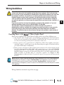
Chapter 4: Installation and Wiring . . . . . . . . . . . . . . . . . . . . . . . . . . .4–1
Safety Guidelines . . . . . . . . . . . . . . . . . . . . . . . . . . . . . . . . . . . . . . . . . . . . . . . . . . .4–2
Introduction . . . . . . . . . . . . . . . . . . . . . . . . . . . . . . . . . . . . . . . . . . . . . . . . . . . . . . .4–3
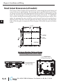
Panel Cutout Dimensions (all models) . . . . . . . . . . . . . . . . . . . . . . . . . . . . . . . . . . .4–4
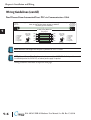
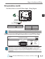
Wiring Guidelines . . . . . . . . . . . . . . . . . . . . . . . . . . . . . . . . . . . . . . . . . . . . . . . . . . .4–5
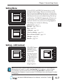
Chapter 5: System Setup Screens . . . . . . . . . . . . . . . . . . . . . . . . . . . .5–1
Introduction . . . . . . . . . . . . . . . . . . . . . . . . . . . . . . . . . . . . . . . . . . . . . . . . . . . . . . .5–2
Accessing the System Setup Screens . . . . . . . . . . . . . . . . . . . . . . . . . . . . . . . . . . . .5–3
System Setup Screens Flowchart . . . . . . . . . . . . . . . . . . . . . . . . . . . . . . . . . . . . . . .5–4
Setup Menu . . . . . . . . . . . . . . . . . . . . . . . . . . . . . . . . . . . . . . . . . . . . . . . . . . . . . . . .5–5
Information Menu . . . . . . . . . . . . . . . . . . . . . . . . . . . . . . . . . . . . . . . . . . . . . . . . . . .5–6
ii
®
EA1-MG6-USER-M Hardware User Manual, 1st Ed. Rev C, 09/10
Table of Contents
Memory . . . . . . . . . . . . . . . . . . . . . . . . . . . . . . . . . . . . . . . . . . . . . . . . . . . . . . . . . .5–6
Protocol . . . . . . . . . . . . . . . . . . . . . . . . . . . . . . . . . . . . . . . . . . . . . . . . . . . . . . . . . .5–6
Extensions . . . . . . . . . . . . . . . . . . . . . . . . . . . . . . . . . . . . . . . . . . . . . . . . . . . . . . . .5–6
Versions . . . . . . . . . . . . . . . . . . . . . . . . . . . . . . . . . . . . . . . . . . . . . . . . . . . . . . . . . .5–6
Setting Menu . . . . . . . . . . . . . . . . . . . . . . . . . . . . . . . . . . . . . . . . . . . . . . . . . . . . . .5–7
LCD Contrast . . . . . . . . . . . . . . . . . . . . . . . . . . . . . . . . . . . . . . . . . . . . . . . . . . . . . .5–7
Backlight, Model EA1-S6ML . . . . . . . . . . . . . . . . . . . . . . . . . . . . . . . . . . . . . . . . . . .5–8
Backlight, Model EA1-S6MLW . . . . . . . . . . . . . . . . . . . . . . . . . . . . . . . . . . . . . . . . .5–9
Beep . . . . . . . . . . . . . . . . . . . . . . . . . . . . . . . . . . . . . . . . . . . . . . . . . . . . . . . . . . .5–10
Calibration . . . . . . . . . . . . . . . . . . . . . . . . . . . . . . . . . . . . . . . . . . . . . . . . . . . . . . .5–11
Clear User Memory . . . . . . . . . . . . . . . . . . . . . . . . . . . . . . . . . . . . . . . . . . . . . . . .5–12
Reset to Factory Default . . . . . . . . . . . . . . . . . . . . . . . . . . . . . . . . . . . . . . . . . . . . .5–12
Hourglass . . . . . . . . . . . . . . . . . . . . . . . . . . . . . . . . . . . . . . . . . . . . . . . . . . . . . . . .5–13
Rotation . . . . . . . . . . . . . . . . . . . . . . . . . . . . . . . . . . . . . . . . . . . . . . . . . . . . . . . . .5–14
Test Menu . . . . . . . . . . . . . . . . . . . . . . . . . . . . . . . . . . . . . . . . . . . . . . . . . . . . . . . .5–15
Serial Port1 - Loop Back Test . . . . . . . . . . . . . . . . . . . . . . . . . . . . . . . . . . . . . . . . .5–15
Serial Port2 - Loop Back Test . . . . . . . . . . . . . . . . . . . . . . . . . . . . . . . . . . . . . . . . .5–16
PLC Enquiry Test . . . . . . . . . . . . . . . . . . . . . . . . . . . . . . . . . . . . . . . . . . . . . . . . . .5–17
Buzzer Test . . . . . . . . . . . . . . . . . . . . . . . . . . . . . . . . . . . . . . . . . . . . . . . . . . . . . .5–17
Touch Panel Test . . . . . . . . . . . . . . . . . . . . . . . . . . . . . . . . . . . . . . . . . . . . . . . . . .5–18
Exit . . . . . . . . . . . . . . . . . . . . . . . . . . . . . . . . . . . . . . . . . . . . . . . . . . . . . . . . . . . . . .5–18
Chapter 6: PLC Communications . . . . . . . . . . . . . . . . . . . . . . . . . . . . .6–1
Introduction . . . . . . . . . . . . . . . . . . . . . . . . . . . . . . . . . . . . . . . . . . . . . . . . . . . . . .6–2
Available PLC Protocols . . . . . . . . . . . . . . . . . . . . . . . . . . . . . . . . . . . . . . . . . . . . . .6–3
C-more 6” Micro-Graphic Communication Ports . . . . . . . . . . . . . . . . . . . . . . . . . . .6–4
DirectLOGIC PLCs Password Protection . . . . . . . . . . . . . . . . . . . . . . . . . . . . . . . . . .6–6
PLC Compatibility and Connection Charts . . . . . . . . . . . . . . . . . . . . . . . . . . . . . . .6–6
AutomationDirect CLICK PLC: . . . . . . . . . . . . . . . . . . . . . . . . . . . . . . . . . . . . . . . . .6–6
Direct LOGIC PLCs RS-422A/RS-485A: . . . . . . . . . . . . . . . . . . . . . . . . . . . . . . . . . . .6–7
Allen-Bradley: . . . . . . . . . . . . . . . . . . . . . . . . . . . . . . . . . . . . . . . . . . . . . . . . . . . . . .6–7
GE, Mitsubishi, Omron, Modicon and Siemens: . . . . . . . . . . . . . . . . . . . . . . . . . . . .6–7
How to use the PLC Compatibility and Connection Charts . . . . . . . . . . . . . . . . . . .6–8
Example: . . . . . . . . . . . . . . . . . . . . . . . . . . . . . . . . . . . . . . . . . . . . . . . . . . . . . . . . .6–8
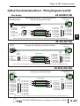
Cables from AutomationDirect . . . . . . . . . . . . . . . . . . . . . . . . . . . . . . . . . . . . . . . .6–15
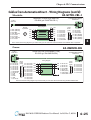
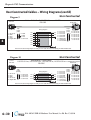
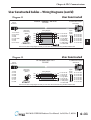
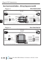
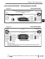
Cables from AutomationDirect – Wiring Diagrams . . . . . . . . . . . . . . . . . . . . . . . .6–17
®
EA1-MG6-USER-M Hardware User Manual, 1st Ed. Rev C, 09/10
iii
Table of Contents
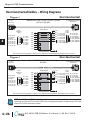
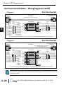
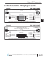
User Constructed Cables – Wiring Diagrams . . . . . . . . . . . . . . . . . . . . . . . . . . . . .6–26
RS-422A/RS-485A Multi-Drop Wiring Diagram Examples . . . . . . . . . . . . . . . . . . .6–34
Chapter 7: Maintenance . . . . . . . . . . . . . . . . . . . . . . . . . . . . . . . . . . . .7–1
Project Backup . . . . . . . . . . . . . . . . . . . . . . . . . . . . . . . . . . . . . . . . . . . . . . . . . . . . . .7–2
Check Operating Environment . . . . . . . . . . . . . . . . . . . . . . . . . . . . . . . . . . . . . . . . .7–2
Check Operating Voltage . . . . . . . . . . . . . . . . . . . . . . . . . . . . . . . . . . . . . . . . . . . . .7–2
Check Transmit and Receive Indicators . . . . . . . . . . . . . . . . . . . . . . . . . . . . . . . . . .7–3
Check Physical Conditions . . . . . . . . . . . . . . . . . . . . . . . . . . . . . . . . . . . . . . . . . . . .7–3
Run Tests under the System Setup Screens . . . . . . . . . . . . . . . . . . . . . . . . . . . . . . .7–4
Check Settings under the System Setup Screens . . . . . . . . . . . . . . . . . . . . . . . . . .7–5
Cleaning the Display Screen . . . . . . . . . . . . . . . . . . . . . . . . . . . . . . . . . . . . . . . . . . .7–5
Check Project Functionality . . . . . . . . . . . . . . . . . . . . . . . . . . . . . . . . . . . . . . . . . . .7–6
Checks from the C-more Micro-Graphic Programming Software . . . . . . . . . . . . . .7–6
Chapter 8: Troubleshooting . . . . . . . . . . . . . . . . . . . . . . . . . . . . . . . . .8–1
C-more Micro-Graphic Panel does not Power up . . . . . . . . . . . . . . . . . . . . . . . . . . .8–2
Display is Blank . . . . . . . . . . . . . . . . . . . . . . . . . . . . . . . . . . . . . . . . . . . . . . . . . . . . .8–2
Display is Dim . . . . . . . . . . . . . . . . . . . . . . . . . . . . . . . . . . . . . . . . . . . . . . . . . . . . . .8–3
No User Program . . . . . . . . . . . . . . . . . . . . . . . . . . . . . . . . . . . . . . . . . . . . . . . . . . .8–3
Lost Firmware – Red ‘Update Mode’ Screen Displayed . . . . . . . . . . . . . . . . . . . . . .8–4
Updating Firmware . . . . . . . . . . . . . . . . . . . . . . . . . . . . . . . . . . . . . . . . . . . . . . . . . .8–4
No Communications between Panel and PC (Personal Computer) . . . . . . . . . . . .8–5
No Communications between Panel and PLC . . . . . . . . . . . . . . . . . . . . . . . . . . . . .8–7
Panel & PLC Error Codes . . . . . . . . . . . . . . . . . . . . . . . . . . . . . . . . . . . . . . . . . . . . .8–8
C-more Micro-Graphic Panel Runtime Errors . . . . . . . . . . . . . . . . . . . . . . . . . . . . . .8–9
Electrical Noise Problems . . . . . . . . . . . . . . . . . . . . . . . . . . . . . . . . . . . . . . . . . . . .8–10
Chapter 9: Replacement Parts . . . . . . . . . . . . . . . . . . . . . . . . . . . . . . .9–1
Replacement Parts Overview . . . . . . . . . . . . . . . . . . . . . . . . . . . . . . . . . . . . . . . . . .9–2
Replacement Parts . . . . . . . . . . . . . . . . . . . . . . . . . . . . . . . . . . . . . . . . . . . . . . . . . .9–2
iv
®
EA1-MG6-USER-M Hardware User Manual, 1st Ed. Rev C, 09/10
Table of Contents
Customizing the Function Keys Insert Label . . . . . . . . . . . . . . . . . . . . . . . . . . . . . .9–3
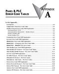
Appendix A: PLC Protocol Error Codes . . . . . . . . . . . . . . . . . . . . . . . .A–1
Introduction . . . . . . . . . . . . . . . . . . . . . . . . . . . . . . . . . . . . . . . . . . . . . . . . . . . . . . .A–2
C-more Micro-Graphic Panel Error Code Table . . . . . . . . . . . . . . . . . . . . . . . . . . . .A–3
Modbus Protocols Error Code P499 Explanation . . . . . . . . . . . . . . . . . . . . . . . . . .A–4
AutomationDirect CLICK . . . . . . . . . . . . . . . . . . . . . . . . . . . . . . . . . . . . . . . . . . . . .A–4
AutomationDirect DirectLOGIC - Modbus (Koyo) . . . . . . . . . . . . . . . . . . . . . . . . . . .A–4
Modicon Modbus RTU . . . . . . . . . . . . . . . . . . . . . . . . . . . . . . . . . . . . . . . . . . . . . .A–4
Entivity Modbus RTU . . . . . . . . . . . . . . . . . . . . . . . . . . . . . . . . . . . . . . . . . . . . . . . .A–4
DirectLOGIC Error Code P499 Explanation . . . . . . . . . . . . . . . . . . . . . . . . . . . . . . .A–5
DirectLOGIC – K-Sequence PLC Error Code Table . . . . . . . . . . . . . . . . . . . . . . . . . .A–5
DirectLOGIC – DirectNET PLC Error Codes . . . . . . . . . . . . . . . . . . . . . . . . . . . . . . . .A–5
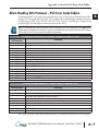
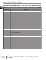
Allen-Bradley Error Code P499 Explanation . . . . . . . . . . . . . . . . . . . . . . . . . . . . . .A–6
Allen-Bradley DF1 Protocol – PLC Error Code Tables . . . . . . . . . . . . . . . . . . . . . . .A–7
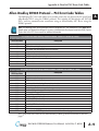
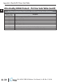
Allen-Bradley DH485 Protocol – PLC Error Code Tables . . . . . . . . . . . . . . . . . . . . .A–9
GE Error Code P499 Explanation . . . . . . . . . . . . . . . . . . . . . . . . . . . . . . . . . . . . . .A–11
GE SNPX Protocol – PLC Error Code Tables . . . . . . . . . . . . . . . . . . . . . . . . . . . . .A–12
Mitsubishi FX Protocol – PLC Error Codes . . . . . . . . . . . . . . . . . . . . . . . . . . . . . . .A–21
Mitsubishi Q / QnA and Q Series – PLC Error Codes . . . . . . . . . . . . . . . . . . . . . .A–21
Omron Error Code P499 Explanation . . . . . . . . . . . . . . . . . . . . . . . . . . . . . . . . . .A–23
Omron Host Link Protocol – PLC Error Code Table . . . . . . . . . . . . . . . . . . . . . . . .A–24
Omron FINS Protocol – PLC Error Code Table . . . . . . . . . . . . . . . . . . . . . . . . . . . .A–25
Siemens Error Code P499 Explanation . . . . . . . . . . . . . . . . . . . . . . . . . . . . . . . . .A–28
Siemens PPI Protocol – PLC Error Code Table . . . . . . . . . . . . . . . . . . . . . . . . . . . .A–29
Appendix B: C-more Micro-Graphic Panel Runtime Errors . . . . . . . . .B–1
Introduction . . . . . . . . . . . . . . . . . . . . . . . . . . . . . . . . . . . . . . . . . . . . . . . . . . . . . . .B–2
Runtime Errors . . . . . . . . . . . . . . . . . . . . . . . . . . . . . . . . . . . . . . . . . . . . . . . . . . . . .B–2
Index
®
EA1-MG6-USER-M Hardware User Manual, 1st Ed. Rev C, 09/10
v
GETTING STARTED
CHHAPTER
1
In This Chapter...
Introduction . . . . . . . . . . . . . . . . . . . . . . . . . . . . . . . . . . . . . . . . . . . . . . . . . . . . . . .1–2
Conventions Used . . . . . . . . . . . . . . . . . . . . . . . . . . . . . . . . . . . . . . . . . . . . . . . . . . .1–3
Product Overview . . . . . . . . . . . . . . . . . . . . . . . . . . . . . . . . . . . . . . . . . . . . . . . . . . .1–4
Agency Approvals . . . . . . . . . . . . . . . . . . . . . . . . . . . . . . . . . . . . . . . . . . . . . . . . . . .1–4
Part Number Key . . . . . . . . . . . . . . . . . . . . . . . . . . . . . . . . . . . . . . . . . . . . . . . . . . .1–5
Product Label Example: . . . . . . . . . . . . . . . . . . . . . . . . . . . . . . . . . . . . . . . . . . . . . .1–5
Serial Number and Date Code format: . . . . . . . . . . . . . . . . . . . . . . . . . . . . . . . . . .1–5
Quick Start Steps . . . . . . . . . . . . . . . . . . . . . . . . . . . . . . . . . . . . . . . . . . . . . . . . . . . .1–6
Step 1 – Unpack and Inspect . . . . . . . . . . . . . . . . . . . . . . . . . . . . . . . . . . . . . . . . . .1–6
Step 2 – Install Optional Hardware Accessories . . . . . . . . . . . . . . . . . . . . . . . . . . . .1–7
Step 3 – Become Familiar with Available Communication Ports . . . . . . . . . . . . . . . .1–8
Step 4 – Install C-more 6” Micro-Graphic Panel . . . . . . . . . . . . . . . . . . . . . . . . . . . .1–9
Enclosure Clearances . . . . . . . . . . . . . . . . . . . . . . . . . . . . . . . . . . . . . . . . . . . . . . .1–10
Step 5 – Connect C-more 6” Micro-Graphic Panel to Computer . . . . . . . . . . . . . .1–11
Step 6 – Provide Power to the C-more 6” Micro-Graphic Panel . . . . . . . . . . . . . . .1–12
Step 7 – Accessing the C-more 6” Micro-Graphic Panel Setup Screens . . . . . . . . .1–13
Step 8 – Choose C-more 6” Micro-Graphic Panel to PLC Protocol & Cables . . . . .1–14
Step 9 – Install the Programming Software and Develop a Project . . . . . . . . . . . .1–15
Step 10 – Connect C-more 6” Micro-Graphic Panel to PLC . . . . . . . . . . . . . . . . . .1–16
Chapter 1: Getting Started
1
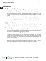
Introduction
The Purpose of this Manual
Thank you for purchasing from our C-more® Micro-Graphic family of products. This manual
describes AutomationDirect.com’s C-more 6” Micro-Graphic panels, their specifications,
included components and available accessories and provides you with important information
for installation, connectivity and setup. The manual shows you how to install, wire and use the
products. It also helps you understand how to interface the panels to other devices in a control
system.
This user manual contains important information for personnel who will install the panels and
accessories, and for the personnel who will be programming the panel. If you understand
control systems making use of operating interfaces such as the C-more Micro-Graphic panels,
our user manuals will provide all the information you need to get, and keep, your system up and
running.
Supplemental Manuals
If you are familiar with industrial control type devices, you may be able to get up and running
with just the aide of the Quick Start Guide that is included with each panel. You may also refer
to the online help that is available in the C-more Micro-Graphic programming software.
Technical Support
We strive to make our manuals the best in the industry. We rely on your feedback to let us know
if we are reaching our goal. If you cannot find the solution to your particular application, or, if
for any reason you need technical assistance, please call us at:
770–844–4200
Our technical support group will work with you to answer your questions. They are available
Monday through Friday from 9:00 A.M. to 6:00 P.M. Eastern Time. We also encourage you to
visit our web site where you can find technical and non-technical information about our
products and our company.
http://www.automationdirect.com
If you have a comment, question or suggestion about any of our products, services, or manuals,
please fill out and return the ‘Suggestions’ card that was included with this manual.
1–2
®
EA1-MG6-USER-M Hardware User Manual, 1st Ed. Rev C, 09/10
Chapter 1: Getting Started
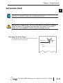
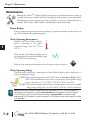
Conventions Used
1
When you see the “notepad” icon in the left-hand margin, the paragraph to its immediate right will be a
special note. The word NOTE: in boldface will mark the beginning of the text.
When you see the “exclamation mark” icon in the left-hand margin, the paragraph to its immediate
right will be a warning. This information could prevent injury, loss of property, or even death (in
extreme cases). The word WARNING: in boldface will mark the beginning of the text.
Key Topics for Each Chapter
The beginning of each chapter will list the key topics
that can be found in that chapter.
Getting Started
CHAPTER
1
In This Chapter...
General Information ............................ ....................................1-2
Spec fications ...................................... ....................................1-4
®
EA1-MG6-USER-M Hardware User Manual, 1st Ed. Rev C, 09/10
1–3
Chapter 1: Getting Started
1
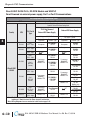
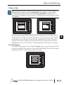
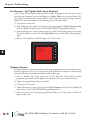
Product Overview
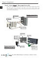
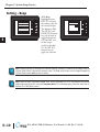
EA1-S6ML
EA1-S6MLW
shown in Landscape (Horizontal) mode
shown in Portrait (Vertical) mode
The C-more 6” Micro-Graphic panel has a 5.7-inch STN LCD monochrome 320 x 240 dot
display. Model EA1-S6ML has five selectable LED-driven backlight colors including Green,
Red, Amber, Yellow and Lime. Model EA1-S6MLW has five selectable LED-driven backlight
colors including White, Pink1, Pink2, Pink3 and Red. Both models feature five user-defined
function keys, each key with a user-defined red LED indicator. The panels can display up to 40
lines by 78 characters of static text and up to 40 lines by 40 characters of dynamic text with
embedded variables and phrases mixed with graphics at landscape orientation. Portrait
orientation can display 59 characters and 40 lines of static text and 40 lines by 40 characters of
dynamic text. Each model is rated NEMA 4/4X, IP-65 (when mounted correctly, for indoor use
only). The C-more 6” Micro-Graphic panels are powered from a 12-24 VDC power supply or
can operate in low-power mode when powered from the serial communications port of select
AutomationDirect PLCs.
Other features include:
• 1792 KB memory
• Built in RJ12 serial communications port (RS-232)
• Built in 15-pin serial communications port (RS-232/422/485)
• Adjustable contrast
• 2 optional keypad bezels, 20-button landscape and 21-button portrait mount
• Optional replaceable clear screen overlay
• Built in Alarm Control setup that activates beep, backlight flash, customized alarm banner, and red
LED blinking
• Up to 999 screens, limited only by memory usage
• 0 to 50 °C (32 to 122 °F) operating temperature range
• UL, cUL & CE agency approvals (see below for details)
• 2-year warranty from date of purchase
Agency Approvals
UL/CUL/CE Certification Numbers
Name
UL/CUL
UL508
CE
ISO-9000
C-more Micro-Graphic Panels
& Accessories
E157382
E157382
EN61131-2
Yes
C
1–4
®
UL
R
US
EA1-MG6-USER-M Hardware User Manual, 1st Ed. Rev C, 09/10
Chapter 1: Getting Started
Part Number Key
1
Panel Part Number Key
The C-more 6” Micro-Graphic panel part numbers consist of the following:
Display Size:
6: 5.7”
Series Name:
EA1: C more Micro Graphic
Display Color:
M: Monochrome
Backlight Type:
L: LED
EA1-S6MLx
Display Type:
S: STN
Features:
blank: Green / Red backlight
W:
White / Red backlight
Bezel Part Number Key
The optional C-more 6” Micro-Graphic keypad bezel part numbers consist of the following:
Series Name:
EA MG6: C more 6” Micro Graphic
Bezel Option Module
EA-MG6-XXXX
Module Type:
BZ2: 20 Key Bezel for landscape mode
BZ2P: 21 Key Bezel for portrait mode
Product Label Example:
R01. 1 2 3 4 5
MODEL:EA1-S6MLW
O
S6
EA1-S6ML
INPUT:12-24V
4 6.5W
5
Date code:****
MADE
D IN CHINA
LISTED
7M17
IND.CONT.EQ.
EA1-S6MLW
EA1-S6MLW
M + serial number
Serial Number and Date Code format:
[Part Number]+[YYMDDFNNN]
YYMF
Serial Number =
Date Code =
YY:
M:
DD:
F:
NNN:
®
Year (07 99 --- e.g. 07 2007)
Month (1 9, X, Y, Z --- e.g. X Oct.)
Day (1 31)
Manufacturing Site (0 9, A Z)
Sequence number for the date listed (000 999)
EA1-MG6-USER-M Hardware User Manual, 1st Ed. Rev C, 09/10
1–5
Chapter 1: Getting Started
1
Quick Start Steps
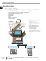
Step 1 – Unpack and Inspect
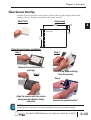
a.) Unpack the C-more 6” Micro-Graphic panel from its shipping carton. Included in the
carton are the following:
• C-more 6” Micro-Graphic panel (EA1-S6ML or EA1-S6MLW)
• DC power connector (EA-MG-DC-CON)
• cutout template
• mounting clips
• gasket
• function key label inserts
• Quick Start Guide
b.) Unpack any accessories that have
been ordered, such as:
Keypad Bezel, programming
cable, PLC communications
cable, etc.
c.) Inspect all equipment for
completeness. If anything is
missing or damaged,
immediately call the
AutomationDirect® returns
department @ 1-800-633-0405.
Mounting
Clips
Function Key
Label Inserts
DC Power
Connector
Cutout
Template
C-more 6 Inch
Micro-Graphic
Panel
Shipping Carton Contents
Optional Accessories
20-Button Horizontal Keypad Bezel
EA-MG6-BZ2
1–6
®
21-Button Vertical Keypad Bezel
EA-MG6-BZ2P
EA1-MG6-USER-M Hardware User Manual, 1st Ed. Rev C, 09/10
Chapter 1: Getting Started
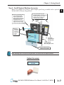
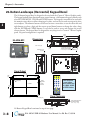
Step 2 – Install Optional Hardware Accessories
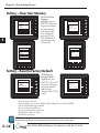
Below is an example of a C-more 6” Micro-Graphic panel being assembled with an optional
EA-MG6-BZ2 20-button Keypad Bezel.
2. Use the (4) Panel Mounting
Clips, EA-MG-BZ2-BRK,
that are supplied with the
panel, to secure panel to
keypad bezel and compress
the gasket between the
panel and the keypad bezel.
Tighten screws to a torque
of 21-28 oz-in [0.15-0.2 Nm].
1
3. Use (8) Bezel Mounting Clips,
EA-MG-BZ2-BRK, to secure keypad
bezel through enclosure cutout.
Tighten screws to a torque of
21-28 oz-in [0.15-0.2 Nm].
Function
Key Label
Insert
1. Remove
Expansion
Connector
Protective
Cover from
rear of
panel.
20 Button
Keypad Bezel
EA MG6 BZ2
C-more 6 Inch
Micro-Graphic Panel
4. Peel Protective Film
from front of panel.
NOTE: Mounting clips for the panel and keypad bezels are included with the respective product.
Optional Accessory
Clear Screen Overlay
EA-6-COV2
®
EA1-MG6-USER-M Hardware User Manual, 1st Ed. Rev C, 09/10
1–7
Chapter 1: Getting Started
Step 3 – Become Familiar with Available Communication Ports
1
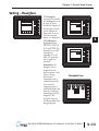
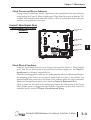
The C-more 6” Micro-Graphic panel includes a built-in RS-232 serial communications port
designated as Port1. This port uses an RJ12 type telephone jack to make connections to either
the EA-MG-PGM-CBL programming cable assembly or a communications cable, such as an
EA-2CBL, to interface with a PLC or controller. The panel can receive power through this port
from the serial communications port on AutomationDirect CLICK™ and select
Direct LOGIC PLCs. The other serial communications port designated as Port2 is a 15-pin Dsub connector that supports RS-232, RS-485 and RS-422.
NOTE: When the 6” panel is powered through Port1 from a connected PLC or PC, the screen brightness is
diminished because the panel is running in Low-Power Mode. For full brightness, connect an external
12-24 VDC power source to the panel’s power connection. Low-Power Mode is intended for initial
programming. For full brightness, connect an external 12-24 VDC power source when the panel is installed
in its application.
RJ12 serial
communications Port1
Expansion
Connector
R01.
2 3 4 5
MODEL:EA1 S6MLW
NPUT:12 24V 6 5W
Date code:** *
MADE IN CH NA
IS ED
7M17
ND.CONT EQ.
EA1-S6MLW + ser al number
8
1
15
9
PLC 15-pin serial
communications Port2
6 5 4 3 2 1
Pin
Signal
1
Logic GND
2
not used
3
RXD (232C)
4
TXD (232C)
5
+5 VDC
6
Logic GND
RS-232
Pin
Signal
Pin
1
Frame GND
6
LE
Signal
Pin
11
Signal
2
TXD (232C)
7
CTS (232C)
12 TXD (422/485)
3
RXD (232C)
8
RTS (232C)
13 Term Resistor
4
Future
9
RXD+ (422/485)
14 do not use
5
Logic GND
10 RXD (422/485)
15 do not use
TXD+ (422/485)
RS-232/422/485
NOTE: See Chapter 2: Specifications and Chapter 6: PLC Communications for additional details on the
available communication ports, protocols and cables.
NOTE: The panel has a built-in RJ12 serial communications port (Port1 - RS-232) and a built in 15-pin serial
communications port (Port2 - RS-232/422/485). Only one of the ports can be used with a connected PLC.
The programming software allows the user to select either Port1 or Port2 under the Panel Manager dialog
box. When using Port2 to communicate with the connected PLC, Port1 can still be used with the EA-MGPGM-CBL Software Programming Cable Assembly to transfer projects between the PC and panel.
1–8
®
EA1-MG6-USER-M Hardware User Manual, 1st Ed. Rev C, 09/10
Chapter 1: Getting Started
Step 4 – Install C-more 6” Micro-Graphic Panel
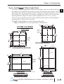
The C-more 6” Micro-Graphic panel can be mounted through a cutout in an enclosure by using
the template that is provided with the panel, or using the dimensions shown below. Cutout
dimensions for the 20-button landscape and 21-button portrait keypad bezel options are also
shown below. The keypad bezels also include a template that can be used. The enclosure
mounting thickness range for the panels and the keypad bezels is 0.04”–0.2” [1–5 mm].
The screw torque range for the screws used on the panel mounting clips and the keypad bezel
mounting clips is 21-28 oz-in [0.15-0.2 Nm].
See Chapter 2: Specifications for additional product dimensions.
Chapter 3: Accessories for accessory specifications and dimensions.
EA1-S6ML & EA1-S6MLW
Panel Cutout
0 260
[6 6]
0 256
[6 5]
+0 04
6 339 0 00
161 0 +10
0 260
[6 6]
+0 04
0 00
2 +10
4 811
0 260
[6 6]
122
1
R 118 [R3]
0 256
[6 5]
CUTOUT
OUTLINE
BEZEL
OUTLINE
0 256
[6 5]
6 339
+0 04
0 00
161 0 +10
R 118 [R3]
CUTOUT
OUTLINE
+0 04
4 811 0 00
122 2 +10
BEZEL
OUTLINE
0 256
[6 5]
CUTOUT
Portrait Mode (Vertical)
CUTOUT
BEZEL
OUTLINE
0 260
[6 6]
CUTOUT
OUTLINE
Landscape Mode (Horizontal)
0 382
[9 7]
CUTOUT
+0 04
0 00
6 +10
9 236
234
0 382
[9 7]
0 382
[9 7]
0 382
[9 7]
9 236
BEZEL
OUTLINE
R0 59 [R1 5]
CUTOUT
+0 04
0 00
0 +10
5 630
143
+0 04
0 00
234 6 +10
CUTOUT
OUTLINE
0 382
[9 7]
0 382
[9 7]
0 382
[9 7]
EA-MG6-BZ2
Landscape (Horizontal)
Keypad Bezel Cutout
®
Units Inches [mm]
R0 59 [R1 5]
5 630
+0 04
0 00
143 0 +10
0 382
[9 7]
EA-MG6-BZ2P
Portrait (Vertical)
Keypad Bezel Cutout
EA1-MG6-USER-M Hardware User Manual, 1st Ed. Rev C, 09/10
1–9
Chapter 1: Getting Started
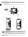
Enclosure Clearances
1
A 1.2” [30mm] minimum clearance is required inside an enclosure for proper ventilation of
the C-more Micro-Graphic panel.
1.2
[30.0]
EA1-S6ML(W)
Rear View
1.2
[30.0]
1.2
[30.0]
R01
MODE : A1 S6M W
N UT 12- 4V 6 5W
D te o e * **
MAD IN HI A
ITD
M7
ND C NT Q.
E 1 S6M W + se a num er
8
1
15
9
1.2
[30.0]
Enclosure
units: inches [mm]
Panel with Keypad
Bezel
Enclosure
Panel only
Enclosure
1.2
[30.0]
1.2
[30.0]
EA1-S6ML(W) with
EA-MG6-BZ2(P)
EA1-S6ML(W)
NOTE: Additional clearance inside the enclosure is required when connecting to the 15-pin serial
communications port (Port2).
1–10
®
EA1-MG6-USER-M Hardware User Manual, 1st Ed. Rev C, 09/10
Chapter 1: Getting Started
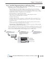
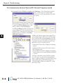
Step 5 – Install the Programming Software and Develop a Project
Following are the minimum system requirements for running C-more Micro-Graphic
Programming Software, EA-MG-PGMSW, on a PC:
1
• Personal Computer with a 333 MHz or higher processor (CPU) clock speed recommended;
(Windows® 2000 with Service Pack 4 or Windows® XP, 800 MHz or higher processor (CPU)
clock speed recommended (Windows® Vista (32 bit)); Intel® Pentium/Celeron family, or AMD®
K6/Athlon/Duron family, or compatible processor recommended
• Keyboard and Mouse or compatible pointing device
• Super VGA color video adapter and monitor with at least 800 x 600 pixels resolution
(1024 x 768 pixels recommended) 64K color minimum
• 150 MB free hard-disk space
• 128 MB free RAM (512 MB recommended); 512 MB free RAM (1GB recommended) for Vista
• CD-ROM or DVD drive for installing software from the CD, or internet access to download free
programming software
• USB port to use with an EA-MG-PGM-CBL, USB to RS232 Programming Cable Assembly for
project transfer from the programming software to the panel
• Operating System - Windows® XP Home / Professional Edition Service Pack 2, Windows® 2000
with Service Pack 4, or Windows® Vista (32 bit)
Insert the supplied CD-ROM into the PC’s CD-ROM drive and follow the instructions. If you
need assistance during the software installation, please refer to the supplied Software Installation
Guide or call the AutomationDirect Technical Support team at 770-844-4200.
Start
Simulate
a Project
Send
Project
Project to panel
Download your project to the
connected panel.
Allows you to check the operation of
your project before downloading it to
the panel.
Make a New Project
Select Project
Location
C \My Documents\C more Projects\ Browse
Project
MyProject
HMI Type
EA1 S6ML
PLC Protocol
DirectLogic K Sequence
Enter a name
for your project
Select the C-more
Micro-Graphic panel
Select the PLC Driver
Protocol Setup
®
EA1-MG6-USER-M Hardware User Manual, 1st Ed. Rev C, 09/10
1–11
Chapter 1: Getting Started
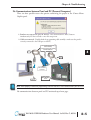
Step 6 – Connect C-more 6” Micro-Graphic Panel to Computer
1
NOTE: Install C-more Micro-Graphic Programming software before connecting the panel to the PC to ensure
the panel drivers install correctly.
Use an EA-MG-PGM-CBL, USB to RS-232 Programming Cable Assembly, from an USB
port type A on the project development PC, through the supplied converter, to the RJ12 RS232 programming/PLC serial communications port on the C-more Micro-Graphic panel as
shown below.
USB to RS-232 Programming Cable Assembly
PC to Panel Programming
Cable Assembly
(Includes serial & USB cables)
EA MG PGM CBL
USB
Cable
Serial
Cable
USB to RS232
Converter
User PC
C-more 6 inch
Micro Graphic
Panel
NOTE: When the panel is powered through Port1 from a connected PLC or PC, the screen brightness is
diminished because the panel is running in Low-Power Mode. For full brightness, connect an external
12-24 VDC power source to the panel’s power connection. Low-Power Mode is intended for initial
programming. For full brightness, connect an external 12-24 VDC power source when the panel is installed
in its application.
1–12
®
EA1-MG6-USER-M Hardware User Manual, 1st Ed. Rev C, 09/10
Chapter 1: Getting Started
Step 7 – Providing Power to the C-more 6” Micro-Graphic Panel
Power can be supplied to the C-more Micro-Graphic panel in one of three different ways.
1.) During operation, the panel functions in High-Power Mode when powered by a minimum 1 Amp
12 - 24 VDC power source. Recommended power supplies are AutomationDirect part number
PSP24-024S or PSP24-024C.
1
2.) The C-more Micro-Graphic panel is powered during programming from the PC through the USB
to RS-232 Programming Cable Assembly, EA-MG-PGM-CBL. The panel will operate in Lowpower mode when powered by the PC and result in a dim screen.
3.) Optionally, the C-more Micro-Graphic panel can function in Low-Power Mode powered from most
AutomationDirect PLC’s RJ12 serial communications port. Use a DV-1000CBL communications
cable, or a DV-1000CBL communications cable with a FA-15HD 15-pin HD DSub/RJ12 Adapter
connected to most AutomationDirect PLC’s 15-pin HD communications port (DL06, D2-250-1
& D2-260) PLCs for Low-Power operation. See Chapter 6: PLC Communications for additional
details. The panel will operate in low-power mode when powered by the PC.
To PLC
RJ12 Port
*Panel Powered from
AutomationDirect PLC via
Communications Cable
Power Supplied to Panel through Cable from CLICK and Direct Logic PLC RJ12 port: To C more
DL05, DL105, DL205, DL350, DL450, H2-WINPLC
Micro Graphic
Serial Port1
RS-232C (p/n DV-1000CBL)
10 feet [3.0 m] Maximum
Wiring Diagram
1
2
3
4
5
6
S g GND
+5 VDC
RXD
TXD
not used
S g GND
RJ12 6 pin
Phone Plug
(6P6C)
GND
6
1
GND
TXD
4
3
RXD
RXD
3
4
TXD
+5 V
2
5
+5 V
GND
1
6
GND
123456
RJ12 6 pin
Phone Plug
(6P6C)
1
2
3
4
5
6
Sig GND
not used
RXD
TXD
+5 VDC
Sig GND
123456
NOTE: When the 6” panel is powered through Port1 from a connected PLC or PC, the screen brightness is
diminished because the panel is running in Low-Power Mode. For full brightness, connect an external
12-24 VDC power source to the panel’s power connection. Low-Power Mode is intended for initial
programming. For full brightness, connect an external 12-24 VDC power source when the panel is installed
in its application.
Panel Powered from a DC Power Source - Wiring Diagram
R 1
MODEL A S6MLW
NPUT:12 2 V . W
a e od :
ADE N CH NA
L TD
M17
I D CO T Q.
EA - 6M W + e al umb r
Recommended
DC Supply Fuse
750 mA fast acting,
ADC p/n AGC 75
GND
Equipment
Ground
8
1
15
9
Supply to Panel
1 A @ 12 24 VDC
(10 8 26 4 VDC)
–
+
NOTE: Recommended DC power supply to power the C-more Micro Graphic Panel, AutomationDirect Part No.
PSP24-024S or PSP24-024C.
®
EA1-MG6-USER-M Hardware User Manual, 1st Ed. Rev C, 09/10
1–13
Chapter 1: Getting Started
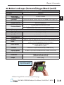
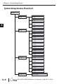
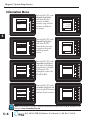
Step 8 – Accessing the C-more 6” Micro-Graphic Panel Setup Screens
To access the Setup Menu of the panel’s setup screens, press the the BAK [F1] and ENT [F5]
function keys simultaneously for three (3) seconds.
1
From the Setup Menu, information about the panel can be obtained, settings can be adjusted,
and panel functions can be tested.
NOTE: See Chapter 5: System Setup Screens for details on using the setup screen settings and functions.
Menu Flow Chart
Setup Menu
[pg 5 5]
1 Information
[pg 5 6]
1 Memory
[pg 5 6]
2 Protocol
[pg 5 6]
3 Extens ons
[pg 5 6]
BAK
4 Versions
[pg 5 6]
SETUP MENU
1
2
3
4
Information
Setting
Test Menu
Exit
2 Setting
[pg 5 7]
>
>
>
>
1 LCD Contrast
[pg 5 7]
UP
2 Backlight
[pg 5 8]
DWN
ENT
3 Beep
[pg 5 10]
ENT
4 Calibration
[pg 5 11]
5 Clear User Memory
[pg 5 12]
6 Reset to Factory Default
[pg 5 12]
7 Hourglass
[pg 5 13]
BAK
8 Rotation
[pg 5 14]
MEMORY
Total
1835008 Bytes
Usage
3 Test Menu
[pg 5 15]
1 Serial Port1
[pg 5 15]
Loop Back Test
2 Ser al Port2
[pg 5 16]
Loop Back Test
26206 Bytes
Free
1808802 Bytes
3 PLC Enquiry Test
[pg 5 17]
4 Buzzer Test
[pg 5 17]
5 Touch Panel Test
[pg 5 18]
4 Exit
[pg 5 18]
1–14
®
Do you want to exit from System Screen?
No[F1] / Yes[F5]
EA1-MG6-USER-M Hardware User Manual, 1st Ed. Rev C, 09/10
Chapter 1: Getting Started
Step 9 – Choose C-more 6” Micro-Graphic Panel to PLC Protocol & Cables
PLC Drivers
Available PLC Protocols
Serial - port2 only
AutomationDirect CLICK
AutomationDirect K-sequence
AutomationDirect DirectNET
AutomationDirect Modbus
Modicon Modbus RTU
Entivity Modbus RTU
Allen-Bradley DF1 Half Duplex
Allen-Bradley DF1 Full Duplex
Allen-Bradley PLC5 DF1
Allen-Bradley DH485
GE SNPX (90/30, 90/70, Micro 90, VersaMax Micro)
Mitsubishi FX
Mitsubishi Q & QnA
Omron Host Link (C200 Adapter, C500)
Omron FINS Serial (CJ1, CS1)
Siemens PPI (S7-200 CPU)
Available purchased cables
Cable Description
Cable Description
Cable Part No.
Cables used with serial Port1
AutomationDirect CLICK, Direct LOGIC
PLC RJ-12 port, DL05, DL06, DL105,
DL205, D3-350, D4-450 & H2-WinPLC
(RS-232C)
DV-1000CBL
Note: The PLC can provide 5 VDC through this cable. No
external 12-24 VDC souce is required, however,
screen brightness is diminished and the alarm beep
will not function.
Direct LOGIC DL405 PLC 15-pin D-sub
port, DL405
(RS-232C)
D4-1000CBL
Direct LOGIC (VGA Style) 15-pin port,
DL06, D2-250 (250-1), D2-260
(RS-232C)
Use with DV-1000CBL cable.
FA-15HD
Direct LOGIC PLC 15-pin D-sub port,
DL405
(RS-232C).
Direct LOGIC PLC RJ-11 port, D3-340
(RS-232C).
1
Serial - port1 or port2
FA-CABKIT
OP-3CBL-1
Cable Part No.
Cables used with serial Port2
AutomationDirect CLICK, Direct LOGIC PLC
RJ-12 port, DL05, DL06, DL105, DL205,
D3-350, D4-450 & H2-WinPLC (RS-232C)
Direct LOGIC (VGA Style) 15-pin port,
DL06, D2-250 (250-1), D2-260
(RS-232C).
Direct LOGIC PLC RJ-11 port, D3-340
(RS-232C).
Direct LOGIC DL405 PLC 15-pin D-sub
port, DL405 (RS-232C).
Direct LOGIC PLC 25-pin D-sub port,
DL405, D3-350, DL305 DCU and all DCM’s
(RS-232C).
Allen-Bradley MicroLogix 1000, 1100,
1200 & 1500 (RS-232C)
Allen-Bradley SLC 5-03/04/05,
ControlLogix, CompactLogix, FlexLogix
DF1 port (RS-232C)
Allen-Bradley PLC-5 DF1 port
(RS-232C)
Allen-Bradley MicroLogix, SLC 5-01/02/03,
PLC5 DH485 port (RS-232C)
GE 90/30, 90/70, Micro 90, Versamax
Micro (Port2) 15-pin D-sub port
(RS-422A)
MITSUBISHI FX Series 25-pin port
(RS-422A)
MITSUBISHI FX Series 8-pin mini-DIN
(RS-422A)
OMRON Host Link (C200 Adapter, C500)
(RS-232C)
EA-2CBL
EA-2CBL-1
EA-3CBL
EA-4CBL-1
EA-4CBL-2
EA-MLOGIX-CBL
EA-SLC-232-CBL
EA-PLC5-232-CBL
EA-DH485-CBL
EA-90-30-CBL
EA-MITSU-CBL
EA-MITSU-CBL-1
EA-OMRON-CBL
NOTE: See Chapter 6: PLC Communications for a detailed chart of PLC compatibility & cable connections.
Chapter 6 includes wiring diagrams for end user construction of certain cables.
®
EA1-MG6-USER-M Hardware User Manual, 1st Ed. Rev C, 09/10
1–15
Chapter 1: Getting Started
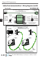
Step 10 – Connect C-more 6” Micro-Graphic Panel to PLC
Connect the serial communications cable between the C-more Micro-Graphic panel and the
PLC. The panel can be connected to the PLC via the panel’s built-in RJ12 serial
communications port (RS-232) or 15-pin serial communications port with either RS-232, RS422 or RS-485 communications.
1
Example of panel’s Port 1
connected to a CLICK PLC
C-more 6 Inch
Micro-Graphic
Panel
CLICK PLC
Port 1
DV 1000CBL
serial cable
Port 2
C-more 6 Inch
Micro-Graphic
Panel
Recommended
DC Supply Fuse
750 mA fast acting,
ADC p/n AGC-75
DL-06 PLC
Port
2
Port
2
Example of panel’s Port 2
connected to a DL06 PLC
1–16
®
PSP-24-024S
Power Supply
C-more to
Direct LOGIC
VGA 15 pin port
serial cable
p/n EA 2CBL 1
EA1-MG6-USER-M Hardware User Manual, 1st Ed. Rev C, 09/10
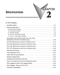
SPECIFICATIONS
CHHAPTER
2
In This Chapter...
Available Models . . . . . . . . . . . . . . . . . . . . . . . . . . . . . . . . . . . . . . . . . . . . . . . . . . . .2–2
Model Specifications . . . . . . . . . . . . . . . . . . . . . . . . . . . . . . . . . . . . . . . . . . . . . . . . .2–3
Panel Dimensions . . . . . . . . . . . . . . . . . . . . . . . . . . . . . . . . . . . . . . . . . . . . . . . . . . .2–5
Communications Ports . . . . . . . . . . . . . . . . . . . . . . . . . . . . . . . . . . . . . . . . . . . . . . .2–6
Chemical Compatibility . . . . . . . . . . . . . . . . . . . . . . . . . . . . . . . . . . . . . . . . . . . . . . .2–7
Chapter 2: Specifications
Available Models
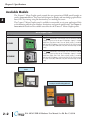
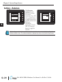
The C-more 6” Micro-Graphic panels expand the next generation of HMI panels brought to
you by AutomationDirect. They have been designed to display and interchange graphical data
from a PLC by viewing, using the function keys, or touching the screen.
The C-more 6” Micro-Graphic panel is available in two models to suit your application. Refer
to the following table for part numbers, descriptions and general specifications. See Chapter 3:
Accessories for details on the available accessories for the C-more 6” Micro-Graphic panels.
2
Micro-Graphic Panels
Part Number
Description
EA1-S6ML
5.7-inch C-more Micro-Graphic Touch Panel with STN LCD monochrome, 320x240
dot display. The panel has red and green LED backlights. Supports 5 selectable
backlight colors (Red, Green, Amber, Lime, and Yellow). Includes 5 user-defined
function keys with LED indicators. 2 built in serial Ports (RS-232 RJ12 port and 15
pin D-sub RS-232/422/485). NEMA 4/4X, IP-65 (when mounted correctly; for indoor
use only).
EA1-S6MLW
5.7-inch C-more Micro-Graphic Touch Panel with STN LCD monochrome, 320x240
dot display. The panel has white and red LED backlights. Supports 5 selectable
backlight colors (White, Pink1, Pink2, Pink3, and Red). Includes 5 user-defined
function keys with LED indicators. 2 built in serial Ports (RS-232 RJ12 port and 15
pin D-sub RS-232/422/485). NEMA 4/4X, IP-65 (when mounted correctly; for indoor
use only
C-more 6” Micro-Graphic
Panel
C-more 6” Micro-Graphic Panels Installed in
Landscape and Portrait Keypad Bezels
2–2
®
EA1-MG6-USER-M Hardware User Manual, 1st Ed. Rev C, 09/10
Chapter 2: Specifications
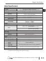
Model Specifications
Specifications
320 x 240 dots LCD display(Landscape Mode),
five user defined keypad function buttons, and five user defined LEDs
Description:
Display:
• Type
2
5 7" STN monochrome LCD, graphical characters
320 (W) x 240 (H) dots (Landscape Mode)
240 (W) x 320 (H) dots (Portrait Mode)
• Resolution
• Color
• Viewing Area Size
• Active Area Size
• Contrast
• Viewing Angle
2 colors (normal / inverse)
4.614” (W) x 3.480” (H) [117.2 mm x 88.4 mm]
4.535” (W) x 3.400” (H) [115.2 mm x 86.4 mm]
Adjusted from the panel’s built-in configuration setup menu
3, 9 o’clock axis –> 45 degrees
6 o’clock axis –> 40 degrees
12 o’clock axis –> 20 degrees
Backlight:
• Type
LED
Model EA1-S6ML : 5 user defined colors:
Red, Green, Amber, Lime, and Yellow
• Color
Model EA1-S6MLW: 5 user defined colors:
White, Pink1, Pink2, Pink3 and Red
• User Replaceable
Touch Screen:
•Type
• Operation
• Life
Features:
• User Memory
• Number of Screens
• Beep (Internal)
• Keypad Function
Buttons
• Keypad Function
Button LEDs
• Serial Communications
• Expansion Connection
No
Analog touch panel
82 gram force [0.8 N] maximum
Minimum of 1,000,000 cycles
1792 kBytes
Up to 999 – limited by project memory usage
Yes
Five user defined function key push buttons with the ability to label.
Minimum of 500,000 cycles
Each function key button includes a red LED that can be user programmed.
Built-in RJ12 serial communications port (RS-232)
and 15-pin D-sub serial communications port (RS-232, RS-485/422).
Yes – used with optional Keypad Bezels, EA-MG6-BZ2 & EA-MG6-BZ2P.
Specification table continued at the top of the next page.
®
EA1-MG6-USER-M Hardware User Manual, 1st Ed. Rev C, 09/10
2–3
Chapter 2: Specifications
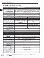
Model Specifications (cont’d)
Specifications (cont’d)
2
Screen Objects:
• Functional Devices
• Static Shapes
• Displayable Fonts
Push Button, Switch, Indicator Button, Indicator Light, Graphic Indicator Light, Numeric
Display, Numeric Entry, Inc/Dec Value, Bar Graph, Bitmap Button, Static Bitmap, Dynamic
Bitmap, Recipe Button, Static Text, Lookup Text, Dynamic Text, Screen Change Push Button,
Screen Selector, Adjust Contrast, Function, Key Configuration Object, Real Time Graph,
Line Graph, Analog Meter.
Lines, Rectangles, Circles and Frames
Fixed fonts: 6x6, 6x8, 8x16, 16x16, 32x16, 32x32, and Windows fonts
Electrical:
Low Power Mode
• Input Voltage Range
• Input Power
• Power Consumption
• Recommended Fuse
• Max. Inrush Current
• Acceptable External
Power Drop
Environmental:
• Operating Temperature
• Storage Temperature
• Humidity
• Environmental Air
• Vibration
• Shock
• Noise Immunity
• Enclosure
• Agency Approvals
High Power Mode
5.0 VDC (4.75 – 5 25 VDC)
12/24 VDC (10.2 – 26.4 VDC)
Supplied through the panel’s RJ12 serial
communications port connection when used Supplied from an external 12-24 VDC power
with most AutomationDirect PLCs having a
source
RJ12 communication port or from a PC during
programming.
6.5 W @ 10.2 VDC (630 mA),
1.05 W @ 5 VDC (210 mA)
12 VDC (540 mA), 24 VDC (250 mA)
No fuse required when directly connected to a
Type AGC fast acting glass fuse,
PLC or PC with recommended cable.
750 mA, 250 VAC, ADC p/n AGC-75
1 A for 500 µs
10 A for 500 µs
Maximum 1 ms
0 to 50 °C (32 to 122 °F)
–20 to +60 °C (–4 to +140 °F)
5–95% RH, non-condensing
No corrosive gases permitted
IEC60068-2-6 (Test Fc), 5-9 Hz: 3.5 mm amplitude, 9-150 Hz: 1.0G, sweeping, at a rate of
1 octave/min. (±10%), 10 sweep cycles per axis on each of 3 mutually perpendicular axes
IEC60068-2-27 (Test Ea), 15 G peak, 11 ms duration, three shocks in each direction
per axis, on 3 mutually perpendicular axes (total of 18 shocks)
NEMA ICS3-304
RFI, (145 MHz, 440 Mhz 10 W @ 10 cm)
Impulse 1000 V @ 1 µs pulse
NEMA 4/4X, IP-65 (When mounted correctly, for indoor use only.)
CE (EN61131-2), UL508, CUL Canadian C22.2 No. 142-M95, UL File E157382
Physical:
6.850” (W) x 5.331” (H) x 2.13” (D) [174.0 mm x 135.4 mm x 54.1 mm] (Landscape Mode)
5.331” (W) x 6.850” (H) x 2.13” (D) [135.4 mm x 174.0 mm x 54.1 mm] (Portrait Mode)
• Dimensions
• Enclosure Mounting
Thickness Range
• Mounting Clip Screw
Torque Range
• Depth from bezel rear
• Weight
2–4
®
0.04” – 0.2” [1 – 5 mm]
21 – 28 oz-in [0.15 – 0.2 Nm]
1.894” [47.1 mm]
30.69 oz. (870 g)
EA1-MG6-USER-M Hardware User Manual, 1st Ed. Rev C, 09/10
Chapter 2: Specifications
Panel Dimensions
6.295
[159.9]
MOUNTING CLIP
(4) places
Panel Dimensions
2.13
1.453
[54.1] 1.689 [36.9]
[42.9]
2
GASKET
6.850
[174.0]
.236
[6.0]
Units: Inches [mm]
4.770
[121.3]
5.331
[135.4]
Enclosure Thickness
ENCLOSURE MOUNTING
THICKNESS RANGE
0.04” - 0.2” [1 - 5mm]
Mounting Clip Screw Torque
MOUNTING CLIP
SCREW TORQUE RANGE
21 - 28 oz-in [0.15-0.2 Nm]
MODE : A - 6MLW
N UT 12 2 V 6 5W
D te od :****
MADE N CH NA
R 11 2 3 4 5
S D
M7
ND.CONT EQ.
EA - 6MLW {0 52 15 011
®
EA1-MG6-USER-M Hardware User Manual, 1st Ed. Rev C, 09/10
2–5
Chapter 2: Specifications
Communications Ports
2
RJ12 serial
communications Port1
Expansion
Connector
R01 1 2 3 4 5
MODEL:EA1 S6MLW
INPUT:12-24V 6.5W
Date code:****
MADE IN CHINA
IS ED
7M17
IND CONT EQ.
EA1-S6MLW + ser al number
8
1
15
9
PLC 15-pin serial
communications Port2
6 5 4 3 2 1
Pin
Signal
1
Logic GND
2
not used
3
RXD (232C)
4
TXD (232C)
5
+5 VDC
6
Logic GND
RS-232
Pin
Signal
Pin
1
Frame GND
6
LE
Signal
Pin
11
Signal
2
TXD (232C)
7
CTS (232C)
12 TXD (422/485)
3
RXD (232C)
8
RTS (232C)
13 Term Resistor
4
Future
9
RXD+ (422/485)
14 do not use
5
Logic GND
10 RXD (422/485)
15 do not use
TXD+ (422/485)
RS-232/422/485
NOTE: The panel has one built-in RJ12 serial communications port (Port1 - RS-232) and one 15-pin serial
communications port (Port2 - RS-232/422/485). Only one of the ports can be used with a connected PLC.
The programming software allows the user to select either Comm. Port1 or Comm. Port2 under the Panel
Manager dialog box. When using Port2 to communicate with the connected PLC, Port1 can still be used with
the EA-MG-PGM-CBL Software Programming Cable Assembly to transfer projects between the PC and panel.
2–6
®
EA1-MG6-USER-M Hardware User Manual, 1st Ed. Rev C, 09/10
Chapter 2: Specifications
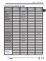
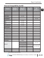
Chemical Compatibility
The C-more Micro-Graphic panels are built of three different materials that may be exposed to
elements outside of the enclosure. The panel’s screen has a polyester (PET) surface. The bezel
uses ABS plastic materials and the panel’s gasket is a silicone rubber material. The following
tables are provided to make you aware of the general compatibility between chemicals that may
be present in your work environment and the various materials used in the manufacture of the
panel. Use the table to determine those chemicals that are safe to use around your C-more
Micro-Graphic panel and those that may harm it. The tables are made up of specifications
provided by the manufacturer of the listed material. The tables rate these chemicals as either
Excellent, Good, Not Recommended, or Not Usable. Because the ratings are for ideal
conditions at room temperature, consider all factors when evaluating your application. Areas left
blank have not been tested by the manufacturer and therefore information of compatibility is
not available.
Chemicals
Screen Sheet – PC
[Density %,
Temperature °C]
Acetaldehyde
Bezel – ABS
[Density %,
Temperature °C]
2
Sheet –
Gasket – Silicone Bezel Key
PET
[Density %,
[Density %,
Temperature °C] Temperature
°C]
Not Recommended
[10, 20 °C] Excellent
[10, 20 °C] Excellent
Acetic Acid
[50, 20 °C] Not Usable
[50-70, 20 °C] Not Usable
[100, 20 °C] Not Usable
Acetic anhydride
Acetone
Acetophenone
Acetylene
Acrylonitrile
Alcohol - Butyl Ether
Alcohol - Ethanol
Alcohol - Isopropyl
Alums NH3, Cr, K
Aluminum acetate
Aluminum bromide
Aluminum chloride
Aluminum nitrate
Aluminum sulfate
Ammonia [anhydrous]
Ammonia gas [cold]
Not Recommended
Not Usable
Not Usable
Excellent
Not Usable
Excellent
Not Recommended
Excellent
Excellent
Excellent
Excellent
Excellent
Good
Good
Excellent
Excellent
Good
Good
Table continued at top of next page.
®
EA1-MG6-USER-M Hardware User Manual, 1st Ed. Rev C, 09/10
2–7
Chapter 2: Specifications
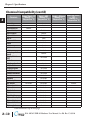
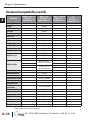
Chemical Compatibility (cont’d)
Chemicals
2
Screen Sheet – PC
[Density %,
Temperature °C]
Bezel – ABS
[Density %,
Temperature °C]
Ammonia liquid
Gasket – Silicone
[Density %,
Temperature °C]
Bezel Key Sheet –
PET
[Density %,
Temperature °C]
Good
[12%] Not Usable
Ammonia water
[28%] Not Usable
Ammonium carbonate
Ammonium chloride
Ammonium hydroxide
[ammonia water]
Ammonium nitrate
Ammonium persulfate
Ammonium phosphate
Ammonium sulfate
Amyl acetate
Amyl alcohol
Aniline dyes
Animal oil [lard]
Aqua regia
Arsenic acid
Asphalt
Barium chloride
Barium hydroxide
Barium sulfate
Barium sulfide
Beer
Beet sugar liquors
Benzaldehyde
Benzene [Benzol]
Benzene
Benzine
Benzyl alcohol
Benzyl benzoate
Benzyl chloride
Borax
Boric acid
Excellent
Excellent
Excellent
Excellent
Excellent
Excellent
Excellent
Not Usable
Good
Not Recommended
Good
Not Usable
Not Recommended
Excellent
Excellent
Excellent
Excellent
Excellent
Excellent
Excellent
Not Recommended
Not Recommended
Excellent
Not Usable
Not Usable
Not Recommended
Not Usable
Not Usable
Excellent
Good
Bromine
Not Usable
Table continued at top of next page.
2–8
®
EA1-MG6-USER-M Hardware User Manual, 1st Ed. Rev C, 09/10
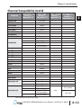
Chapter 2: Specifications
Chemical Compatibility (cont’d)
Chemicals
Screen Sheet – PC
[Density %,
Temperature °C]
Butane
Butter
Butyl acetate
Butyl acrylate
Butyl alcohol
Butyl Cellosolve
Calcium actetate
Calcium bisulfite
Calcium chloride
Calcium hydroxide
Calcium hypochlorite
Calcium nitrate
Calcium sulfide
Cane sugar liquors
Carbon dioxide
Carbon disulfide
Carbonic acid
Carbon tetrachloride
Castor oil
China wood [tung] oil
Chlorine gas [dry]
Chlorine gas [wet]
Chlorine liquid
Chlorinated solvents
Chloroacetic acid
Chloroacetone
Chloroform
Chlorophenol
Chlorosulfonic acid
Chlorotoluene
Bezel – ABS
[Density %,
Temperature °C]
Gasket – Silicone
[Density %,
Temperature °C]
Bezel Key Sheet–
PET
[Density %,
Temperature °C]
2
Excellent
Good
Not Usable
Not Usable
[Butanol] Good
Not Usable
Excellent
Good
Excellent
Excellent
[20, 20 °C] Excellent
Excellent
Excellent
Excellent
Excellent
Not Usable
Good
Not Usable
Excellent
Not Recommended
Excellent
Not Usable
Not Usable
Not Usable
Not Usable
Not Usable
Not Usable
Not Usable
Excellent
Not Usable
Not Usable
Not Usable
[2, 70 °C] Not Usable
[5, 70 °C] Not Usable
Chromic acid
[10, 70 °C] Not Usable
[25, 70 °C] Not Usable
Table continued at top of next page.
®
EA1-MG6-USER-M Hardware User Manual, 1st Ed. Rev C, 09/10
2–9
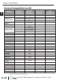
Chapter 2: Specifications
Chemical Compatibility (cont’d)
Chemicals
2
Screen Sheet – PC
[Density %,
Temperature °C]
Citric acid
Cocoanut oil
Concentrated HCI
Copper chloride
Copper cyanide
Copper sulfate
Corn oil
Cottonseed oil
Creosol
Cyclohexane
Cyclohexanol
Cyclohexanone
Developing solutions
[Hypos]
Dibutyl phthalate
[DBP]
Dichlorobenzene
Diethylene glycol
Diethyl ether
Disopropyl ketone
Dimethyl aniline
Dimethyl formamide
Dioxane
Dipentene
Epichlorohydrine
Ethyl acetate
Ethyl acetoacetate
Ethyl acrylate
Ethyl alcohol
Ethyl benzene
Ethyl chloride
Ethylene chlorohydrin
Ethylene diamine
Ethylene dichloride
Ethylene glycol
Bezel – ABS
[Density %,
Temperature °C]
Gasket – Silicone
[Density %,
Temperature °C]
Bezel Key Sheet –
PET
[Density %,
Temperature °C]
Good
Good
Excellent
Excellent
Excellent
Excellent
Good
Good
Not Usable
Good
Good
Not Usable
Not Usable
Excellent
Not Usable
Not Usable
Good
Not Usable
Not Usable
Not Usable
Not Usable
Not Usable
Not Usable
Not Usable
Not Usable
Not Usable
Excellent
Not Usable
Not Usable
Not Recommended
Excellent
Not Usable
Not Usable
Not Usable
Not Usable
Not Usable
Excellent
Table continued at top of next page.
2–10
®
EA1-MG6-USER-M Hardware User Manual, 1st Ed. Rev C, 09/10
Chapter 2: Specifications
Chemical Compatibility (cont’d)
Chemicals
Screen Sheet – PC
[Density %,
Temperature °C]
Ethylene oxide
Fatty acid
Ferric chloride
Ferric nitrate
Ferric sulfate
Fluorboric acid
Fluorobenzene
Fluosilicic acid
Bezel – ABS
[Density %,
Temperature °C]
Sheet –
Gasket – Silicone Bezel Key
PET
[Density %,
[Density %,
Temperature °C] Temperature
°C]
2
Not Usable
Good
Excellent
Excellent
Excellent
Not Recommended
Not Usable
Not Recommended
[40, 20 °C] Good
[25, 20 °C] Excellent
Formaldehyde
[50, 20 °C] Good
[90, 20 °C]
Not Recommended
Freon
Freon 11
Freon 12
Freon 113
Freon 114
Fuel oil
Gasoline
Gelatin
Glauber’s salt
Glue
Glycerin
Grease
Hexane
Hexyl alcohol
[45° C] Excellent
Not Recommended
Good
Not Usable
Not Recommended
Good
Excellent
Not Recommended
Not Usable
Excellent
Excellent
Excellent
Excellent
Excellent
Not Recommended
Good
[20, 20 °C] Not Usable
Hydrobromic acid
[20-70, 20 °C] Not Usable
[37, 20 °C] Not Usable
[10, 20 °C] Excellent
[20, 20 °C] Good
[20-80, 20 °C]
Not Recommended
[38, 20 °C]
Not Recommended
Hydrochloric acid
[15%] Excellent
Good
[30%] Good
Table continued at top of next page.
®
EA1-MG6-USER-M Hardware User Manual, 1st Ed. Rev C, 09/10
2–11
Chapter 2: Specifications
Chemical Compatibility (cont’d)
Chemicals
2
Screen Sheet – PC
[Density %,
Temperature °C]
Bezel – ABS
[Density %,
Temperature °C]
Hydrocyanic acid
Gasket – Silicone
[Density %,
Temperature °C]
Bezel Key Sheet –
PET
[Density %,
Temperature °C]
Excellent
[10, 20 °C] Excellent
Hydrofluoric acid
[20, 20 °C] Excellent
[40,RT] Good
Hydrofluoric acid
anhydrous
Hydrogen
Not Usable
Excellent
[5, 20 °C]
Not Recommended
[5-50, 20 °C]
Not Recommended
[30, 20 °C] Not Usable
Hydrogen peroxide
Hydrogen sulfide
Hydorquinone
Hypochlorous acid
Isobutyl alcohol
Isopropyl acetate
Isopropyl alcohol
JP fuels (1-6)
Kerosene
Lacquer
Lactic acid
Lard
Lead acetate
Lead nitrate
Lead sulfamate
Linoleic acid
Linseed oil
Liquified petroleum
gas [LPG]
Lubricating oil
Lye solution
Magnesium chloride
Magnesium hydroxide
Magnesium sulfate
Maleic acid
Excellent
Not Recommended
Not Recommended
Good
Not Usable
Excellent
Good
Good
Good
Not Usable
Excellent
Excellent
Excellent
Good
Good
Excellent
Excellent
Excellent
Excellent
Excellent
Excellent
Excellent
Excellent
Excellent
Table continued at top of next page.
2–12
®
EA1-MG6-USER-M Hardware User Manual, 1st Ed. Rev C, 09/10
Chapter 2: Specifications
Chemical Compatibility (cont’d)
Chemicals
Screen Sheet – PC
[Density %,
Temperature °C]
Marcuric chloride
MEK
Mercury
Metacresol
Methyl acetate
Methyl alcohol
Methyl Benzoate
Methyl chloride
Methyl ethyl ketone
[MEK]
Methyl isobutyl ketone
[MIBK]
Methyl methacrylate
Methyl dichloride
Methyl Salicylate
Milk
Mineral oil
Monochlorobenzene
Naptha
Napthalene
Napthenic acid
Natural gas
Natural oil
Nickel acetate
Nickel chloride
Nickel sulfate
Bezel – ABS
[Density %,
Temperature °C]
Sheet –
Gasket – Silicone Bezel Key
PET
[Density %,
[Density %,
Temperature °C] Temperature
°C]
2
Excellent
Not Usable
Good
Excellent
Not Usable
Not Usable
Not Recommended
Excellent
Not Usable
Not Usable
Not Usable
Not Usable
Not Usable
Not Usable
Not Usable
Not Usable
Excellent
Excellent
Excellent
Not Usable
Not Usable
Good
Excellent
Good
Excellent
Excellent
Excellent
Excellent
Excellent
[10, 20 °C] Good
[10-70, 20 °C] Not Usable
[30%] Good
[30, 20 °C] Not Usable
Nitric acid
[30-70, 20 °C] Not Usable
[61.3, 20 °C] Not Usable
[30%] Not Usable
[Vapor, RT] Not Usable
Nitrobenzene
Nitroethane
Nitromethane
Not Usable
Not Usable
Not Usable
Not Usable
Table continued at top of next page.
®
EA1-MG6-USER-M Hardware User Manual, 1st Ed. Rev C, 09/10
2–13
Chapter 2: Specifications
Chemical Compatibility (cont’d)
Chemicals
2
Screen Sheet – PC
[Density %,
Temperature °C]
Nitropropane
Nitrogen
Octyl alcohol
Oleic acid
Olive oil
Oxalic acid
Oxygen
Ozone
Palmitic acid
Perchloroethylene
Petroleum
Phenol
Bezel – ABS
[Density %,
Temperature °C]
Sheet –
Gasket – Silicone Bezel Key
PET
[Density %,
[Density %,
Temperature °C] Temperature
°C]
Not Usable
Excellent
Good
Excellent
Excellent
Excellent
Excellent
Not Recommended
Excellent
Not Usable
Excellent
Not Usable
Not Usable
[50, 20 °C] Good
Phospheric acid
[50-70, 20 °C] Not Usable
[75, 20 °C] Not Usable
[Sulfuric acid 20%
+ nitric acid 4%] Good
Pickling solution
[Sulfuric acid 40%
+ nitric acid 15%]
Not Recommended
Good
Pine oil
Potassium chloride
Potassium cyanide
Potassium dichromate
Potassium hydroxide
Potassium nitrate
Potassium
permangante
Potassium sulfate
Propane
Propyl acetate
Propyl alcohol
Salt water
Silicone oils
Silver nitrate
Excellent
Excellent
[10, 20 °C] Excellent
Excellent
[10%] Not Usable
Excellent
[5, 20 °C] Excellent
Excellent
Excellent
Not Usable
Good
Excellent
Good
Excellent
Table continued at top of next page.
2–14
®
EA1-MG6-USER-M Hardware User Manual, 1st Ed. Rev C, 09/10
Chapter 2: Specifications
Chemical Compatibility (cont’d)
Chemicals
Screen Sheet – PC
[Density %,
Temperature °C]
Bezel – ABS
[Density %,
Temperature °C]
Skydrol 500
Skydrol 7000
Soap solutions
Soda ash
Sodium bicarbonate
Sodium bisulfate
Sodium borate
Sodium carbonate
Sodium chloride
Sodium cyanide
Sheet –
Gasket – Silicone Bezel Key
PET
[Density %,
[Density %,
Temperature °C] Temperature
°C]
2
Not Usable
Not Usable
Excellent
Excellent
Excellent
Good
Excellent
[10%] Excellent
Excellent
Excellent
[10, 20 °C] Excellent
Sodium hydroxide
[30, 20 °C] Excellent
[30-70, 20 °C] Not Usable
Good
[1%] Excellent
[10%] Not Usable
[5, 20 °C] Excellent
Sodium hydrochlorite
[5-70, 20 °C] Not Usable
Sodium
metaphosphate
Sodium nitrate
Sodium perborate
Sodium peroxide
Sodium phosphate
Sodium thiosulfate
Sodium sulfate
[Glauber’s salt]
Sodium sulfite
Soybean oil
Stannic chloride
Excellent
Excellent
Excellent
Not Usable
Excellent
Excellent
Good
Excellent
Excellent
Good
[below 150 degrees]
Not Usable
[above 150 degrees]
Not Usable
Excellent
Steam
Steam
Stearic acid
Styrene
Sucrose solutions
Sulfur
Sulfur dioxide
Not Recommended
Excellent
Excellent
Good
Table continued at top of next page.
®
EA1-MG6-USER-M Hardware User Manual, 1st Ed. Rev C, 09/10
2–15
Chapter 2: Specifications
Chemical Compatibility (cont’d)
Chemicals
2
Screen Sheet – PC
[Density %,
Temperature °C]
Bezel – ABS
[Density %,
Temperature °C]
Gasket – Silicone Bezel Key – PET
[Density %,
[Density %,
Temperature °C] Temperature °C]
[10, 20 °C] Excellent
[20%] Excellent
[10-70, 20 °C] Not Usable
[30, 20 °C] Excellent
Sulfuric acid
[30-70, 20 °C]
Not Recommended
Not Usable
[98, 20 °C] Not Usable
[80%] Not Usable
[Vapor, 20 °C] Not Usable
Sulpherous acid
Tannic acid
Tar
Tartaric acid
Terpineol
Tetrachloroethane
Tetraethyl lead
Tetralin
Tetrahydrofuran
Thionyl chloride
Toluene
Trichloroethylene
[Trichlene]
Triethanol amine
Turpentine oil
Vegetable oil
Vinegar
Water
Whiskey
Xylene
Zeolites
Zinc acetate
Zinc chloride
Zinc sulfate
2–16
[60%] Excellent
[10, 20 °C] Good
Good
Not Recommended
Excellent
Not Recommended
Not Usable
Excellent
Good
Not Usable
Not Usable
Not Usable
Not Usable
Not Usable
Not Usable
Not Usable
Excellent
Not Usable
Good
Good
Good
Excellent
Excellent
Excellent
Not Usable
Not Usable
Excellent
Excellent
Excellent
Excellent
Excellent
Excellent
®
EA1-MG6-USER-M Hardware User Manual, 1st Ed. Rev C, 09/10
ACCESSORIES
CHHAPTER
3
In This Chapter...
Accessories . . . . . . . . . . . . . . . . . . . . . . . . . . . . . . . . . . . . . . . . . . . . . . . . . . . . . . . .3–2
C-more Micro-Graphic Programming Software . . . . . . . . . . . . . . . . . . . . . . . . . . . .3–3
USB to RS-232 Programming Cable Assembly . . . . . . . . . . . . . . . . . . . . . . . . . . . . .3–6
20-Button Landscape (Horizontal) Keypad Bezel . . . . . . . . . . . . . . . . . . . . . . . . . .3–8
21-Button Portrait (Vertical) Keypad Bezel . . . . . . . . . . . . . . . . . . . . . . . . . . . . . .3–11
D-SUB 15-pin 90-degree Communication Port Adapter . . . . . . . . . . . . . . . . . . . .3–14
D-SUB 15-pin to Terminal Block Adapter . . . . . . . . . . . . . . . . . . . . . . . . . . . . . . . .3–14
Clear Screen Overlay . . . . . . . . . . . . . . . . . . . . . . . . . . . . . . . . . . . . . . . . . . . . . . . .3–15
Chapter 3: Accessories
Accessories
Micro-Graphic Programming Software & Programming Cable
Part Number
3
Description
C-more Micro-Graphic panel Windows-based configuration software.
Requires Windows 2000 with Service Pack 4, XP Home or Professional
with Service Pack 2 or Windows Vista. Requires USB port connection
from PC to touch panel. Includes CD-ROM. Programming cable
(EA-MG-PGM-CBL) sold separately. Downloadable version available
from the Web site at no charge. Software Help Files included in
download.
6-ft. cable assembly to connect personal computer to any C-more
Micro-Graphic panel for setup and programming. (Note: This cable
assembly uses the PC's USB port and converts the signals to serial
transmissions. The USB port supplies 5 VDC to the Micro-Graphic
panel for low-power mode configuration operations). Assembly
includes standard USB A-type connector to B-type connector cable,
custom converter, and an RS232C cable with RJ12 modular connector
on each end.
EA-MG-PGMSW
EA-MG-PGM-CBL
Micro-Graphic Panel Accessories
Part Number
Description
EA-MG6-BZ2
For Landscape (Horizontal) Mounted Panels. 20-button keypad bezel
with numeric keypad for C-more 6” Micro-Graphic panels, 4 arrow
adjust keys, and ESCAPE, MENU, CLEAR and ENTER buttons. Helps to
reduce screen wear in heavy-duty applications where operators can
use the keypad to enter numeric data. Designed for easy drop-in of the
Micro-Graphic panels.
EA-MG6-BZ2P
For Portait (Vertical) Mounted Panels. 21-button keypad bezel with
numeric keypad for C-more 6” Micro-Graphic panels, 4 arrow adjust
keys, and ESCAPE, MENU, CLEAR and (2) ENTER buttons. Helps to
reduce screen wear in heavy-duty applications where operators can
use the keypad to enter numeric data. Designed for easy drop-in of the
Micro-Graphic panels.
EA-6-COV2
Optional clear screen overlay used to protect C-more Micro-Graphic
displays from minor scratches and wear. Package contains 3 clear
screen overlays.
3–2
®
EA1-MG6-USER-M Hardware User Manual, 1st Ed. Rev C, 09/10
Chapter 3: Accessories
C-more Micro-Graphic Programming Software
C-more® Micro-Graphic Programming Software is a
spin-off of its powerful sibling C-more Touch Panel. It
offers very high end features designed to reduce your
configuration time. Simply drag and drop the objects from
the object bar (right side of screen) onto the the screen
construction area. Then configure your PLC tags and click
on the objects you wish to use. Use the built-in simulator to review your work on your PC
before ever downloading your project!
3
NOTE: Software and Firmware Version 2.0 or later is required with models EA1-S6ML and
EA1-S6MLW. Available for free download at www.automationdirect.com.
Thumbnail project preview pane
Helps keep track of multi-screen projects.
Built-in user object/screen libraries
Save time by re-using your custom objects
and screens.
Scrolling object selection window
Lets you find the object you want fast. Just
drag and drop it on the screen.
Scrolling help window
Gives you helpful information on each object
Built-in project simulator
• Runs your project on your PC
• Test all of your screens before downloading
• Time savings pays for the panel
PC Requirements:
Following are the minimum system requirements for running C-more 6” Micro-Graphic
Programming Software, EA-MG-PGMSW, on a PC:
• USB port for project transfer from software to touch panel
• Personal Computer with a 333 MHz or higher processor (CPU) clock speed recommended;
(Windows® 2000 with Service Pack 4 or Windows® XP, 800 MHz or higher processor (CPU)
clock speed recommended (Windows® Vista (32 bit)); Intel® Pentium/Celeron family, or AMD®
K6/Athlon/Duron family, or compatible processor recommended
• Keyboard and Mouse or compatible pointing device
• Super VGA color video adapter and monitor with at least 800 x 600 pixels resolution
(1024 x 768 pixels recommended) 64K color minimum
• 150 MB free hard-disk space
• 128 MB free RAM (512 MB recommended); 512 MB free RAM (1GB recommended) for Vista
• CD-ROM or DVD drive for installing software from the CD or internet access to download
• Operating System - Windows® XP Home / Professional Edition with Service Pack 2, Windows®
2000 with Service Pack 4, Windows® Vista or Windows® 7.
®
EA1-MG6-USER-M Hardware User Manual, 1st Ed. Rev C, 09/10
3–3
Chapter 3: Accessories
Micro-Graphic Programming Software (cont’d)
C-more Micro-Graphic Panel Objects
Object
3
Graphic
Object
The Line object, just like with drawing tools, allows the user to insert a
straight line drawing into a project. When a Line is inserted into a
project, a window opens to allow the user to setup all available
parameters for the Line object. Some of the uses for Line Objects
include but are not limited to adding callouts, pointers, or indicators.
The Numeric Display consists of a frame that displays a real-time
numeric value according to the value of data received from an assigned
Tag Name. The Numeric Display supports numeric Signed Decimal,
Unsigned Decimal, BCD, and Floating Point data types with up to 11
digits, including decimal point. User Defined Alpha Numeric Prefix and
Suffix values are also supported.
The Rectangle object, just like with drawing tools, allows the user to
insert a drawing of a Rectangle as well as other geometric shapes into
a project. When this object is inserted into a project, a window opens to
allow the user to setup all available parameters for the Rectangle object.
The Numeric Entry object is used to enter a value from your Panel to
a PLC Register. This object, when selected, opens a Numeric Keypad
that allows the user to enter a new value that will be written to the
assigned Tag Name. The Numeric Entry supports numeric Signed
Decimal, Unsigned Decimal, BCD, and Floating Point data types with up
to 11 digits, including decimal points. User Defined Alpha Numeric Prefix
and Suffix values are also supported.
The Circle object, just like with drawing tools, allows the user to insert
a drawing of a Circle or ellipse shape into a project. When this object is
inserted into a project, a window opens to allow the user to setup all
available parameters for the Circle object.
The Increment/Decrement Value object is used to add or subtract a
value by pressing a button on the Panel. Basically the object uses two
Tags, one to read a value from and another to write a modified value to.
The Increment/Decrement Value supports numeric Signed Decimal,
Unsigned Decimal, BCD, and Floating Point data types with up to 11
digits, including decimal points. The Increment and decrement values
are also user selectable.
The Frame object allows the user to insert a Frame to the project that
can be used to Frame other objects. Some of the uses for Frame object
include but are not limited to graphically separating objects for different
operations that may appear on one screen and emphasizing
pushbuttons or other objects that may require more attention by the
operator.
The Real Time Graph object displays the value stored in up to two PLC
tags, over a history of up to 24 points each. One point is added at each
refresh.
The Pushbutton object is available from the Button Category of the
Object List window. The Pushbutton object is an electronic version of a
typical Pushbutton normally found on control panels. The Pushbutton
object can be used to activate or deactivate components assigned to a
Discrete Tag Name.
The Line Graph object displays the values of up to 24 PLC address
points. Up to two address arrays can be displayed. The line is drawn in
its entirety at each refresh.
The Switch object is an electronic version of a typical Switch that
normally can be found on control panels. The Switch object can be used
to activate or deactivate components assigned to a Discrete Tag Name.
The Analog Meter object is used to display the current value of a Tag
Name.
The Indicator Button object is available from the Button Category of
the Object List window. The Indicator Button object is an electronic
version of a typical Indicator Button normally found on control panels.
The Indicator Button is a combination of a Pushbutton and an Indicator
Light. The Indicator Button can be used to activate or deactivate
components assigned to a Discrete Tag Name.
The Bar Meter object is used to monitor up to two assigned Tag Names
continuously. This object has various appearances depending upon the
relative value of the tags. The Bar Meter can be used to create digital
versions of level, current, and flow meters to name a few samples, or
gauges that measure speed and other measurable data.
The Indicator Light object is an electronic version of a typical Indicator
Light normally found on industrial control panels. The Indicator Light can
be configured to display the status of the assigned Discrete Tag Name.
The Bitmap Button object offers the ability to use a Bitmap graphic to
perform the functions of a Button. This allows users to create their own
graphics and implement them within the software project. The Bitmap
Button object can be used to activate or deactivate components
assigned to a Discrete Tag Name. The C-more Micro-Graphic display
only supports two colors, black and white.
The Graphic Indicator Light object is a more enhanced version of the
“Indicator Light Object” that allows the user to choose more detailed
graphics to display the status of a tag. This object is an electronic
version of a typical Indicator Light normally found on industrial control
panels. The Indicator Light can be configured to display the status of the
assigned Discrete Tag Name.
The Static Bitmap offers the ability to display a Bitmap graphic on any
screen. The Static Bitmap does not change state. Refer to the Dynamic
Bitmap Object if you require the graphic object to change state based
on a Tag Value in your PLC. The dialog box for a "Static Bitmap" object
allows you to "read from disk" and select a graphic file for import.
Graphics must be in one of the following formats: .BMP .WMF .JPG
.JPEG
C-more Micro-Graphic Panel Objects continued at top of next page.
3–4
®
EA1-MG6-USER-M Hardware User Manual, 1st Ed. Rev C, 09/10
Graphic
Chapter 3: Accessories
Micro-Graphic Programming Software (cont’d)
C-more Micro-Graphic Panel Objects
Object
Graphic
Object
Recipe objects make it easy to make a large number of tag changes
with the push of a single button. Create Recipes with up to 99 entries,
and multiple sets of values. Then just push a button to load an entire set
of values into the group of recipe tags.
The Scroll Text object is available from the Text Category of the Object
List window. The Scroll Text object is an electronic version of a marquee.
It is similar to the Static Text Object. If the text in the object does not fit
in the window, it will scroll from right to left across the window. The Scroll
Text object does not require a Tag Name assignment. The Scroll Text
Object has a maximum character limit of 128 characters.
The Dynamic Bitmap object offers the ability to make an object using
two different Bitmap graphics that will display one graphic when the Tag
is On and a different graphic when the Tag is Off. Use your own bitmap
designs or use some of the bitmaps provided with the software that are
located in the User Graphic Library.
The Screen Change Pushbutton object is available from the Control
Category of the Object List window. The Screen Change Pushbutton
object is a pushbutton that can be configured to activate another screen
in the project. This object may be edited to various colors and sizes.
Users can configure the button to activate the Power-Up screen,
Forward Screen, Previous Screen, or any one of the project screens.
The Static Text object is used to display a Frame with a personalized
Message. This Frame and Message can be placed on any screen and
any location within the screen.
The Screen Selector object is available from the Control Category of
the Object List window. This object is an enhanced version of the
Screen Change pushbutton in that it offers many more features and
defaults with data from screens in the project. This helps to save time by
not having to create Screen change buttons for each screen. This object
may be edited to various colors and sizes.
The Lookup Text object is used to display a Frame with a personalized
Message. This Frame and Message can be placed on any screen and
any location within the screen. The object is always displayed like a sign
but is configured to display only the message prompted by an assigned
Tag Name. Messages are retrieved from a Message Database which is
configured by the user with text defined by the user. The Lookup Text
Object will scroll text up to 128 characters.
The Adjust Display Contrast object is used to allow the operator to
adjust the Panel Display Contrast. The default Display setting often
works in most applications, however lighting may vary based on the
location of each application. In these cases the operator can use this
object to make adjustments. The current display setting value will
appear on the top of the button and will change as the arrow keys are
pressed. This button can be modified to various sizes.
The Dynamic Text object is used to display text that is retrieved from
data stored in a Tag. The Tag Name is assigned to registers in the PLC
that contain set character data. The data can be stored in the PLC in
ASCII format and may include information such as machine numbers,
locations, part numbers, and such. The Message can be configured to
be visible (Trigger) when an associated Tag Name is On or Off. This
object can be placed on any screen and any location within the screen.
The Dynamic Text Object will scroll text up to 40 characters.
The Function object is used to assign the panels function key buttons
to a particular action as well as assigning the control of the LED On/Off
status. When a button has been assigned as a shift button, the then F1
through F5 will become F6 through F10. The Function Object buttons
will activate when the hardware button is pressed or when the object is
pressed on the screen. The object size is restricted so that the keys will
line up with the hardware function keys on the panel.
®
EA1-MG6-USER-M Hardware User Manual, 1st Ed. Rev C, 09/10
Graphic
3
3–5
Chapter 3: Accessories
USB to RS-232 Programming Cable Assembly
Using the C-more Micro-Graphic Programming Software for project development, the
C-more 6” Micro-Graphic panel can be connected to a PC (personal computer) by using the
USB-to-RS-232 cable assembly, part number EA-MG-PGM-CBL.
3
• Connect the USB programming cable ( included) from a USB port type A on the PC to the USB type
B port on the converter (included). Next connect the serial programming cable from the converter’s
RJ12 port to the panel’s RJ12 serial port. The panel receives power from the USB port of the PC that
it is connected to through the USB to RS-232 converter assembly.
NOTE: Install C-more Micro-Graphic Programming software before connecting the panel to the PC to ensure
the panel drivers install correctly.
EA-MG-PGM-CBL
Converter Dimensions
Converter Status LEDs
LED Status Indicators
RxD
TxD
PWR
PC to Panel Programming
Cable Assembly
(Includes serial & USB cables)
EA-MG-PGM-CBL
USB Connectivity
USB
Cable
Serial
Cable
USB to RS232
Converter
User PC
C-more 6 inch
Micro Graphic
Panel
USB to RS-232 Programming Cable Assembly continued at top of next page.
3–6
®
EA1-MG6-USER-M Hardware User Manual, 1st Ed. Rev C, 09/10
Chapter 3: Accessories
USB to RS232 Programming Cable Assembly (cont’d)
USB to RS232 Converter Specifications
Part Number:
EA-MG-PGM-CBL
Description:
6-ft. cable assembly to connect personal computer to any C-more Micro-Graphic panel for
setup and programming. (Note: This cable assembly uses the PC's USB port and converts the
signals to serial transmissions. The USB port supplies 5 VDC to the C-more Micro-Graphic
panel for low-power mode configuration operations.) Assembly includes standard USB Atype connector to B-type connector cable, custom converter, and an RS232C cable with RJ12
modular connector on each end.
3
Hardware:
• USB Interface
• Serial Interface
• Baud Rate
• Input Voltage
• Power Consumption
Accessory Cables:
• USB Cable
• Serial Cable
Environmental:
• Operating Temperature
• Storage Temperature
• Humidity
• Environmental air
• Vibration
• Shock
USB Specification Rev. 1.1
Connector: USB Type B jack to accept USB Type B cable plug
RS232 (EIA-232-E)
Connector: RJ12 phone jack 6p to accept RJ12 cable plug
115.2 kbps Maximum
5 VDC (Supplied thru serial interface cable.)
50 mA (Does not include power to panel and/or bezel.)
USB Type A plug to PC on one end, USB Type B plug to converter on other end,
0.30 m [1 foot] length (* Note)
RJ12 phone plug connectors on both ends, 2.0 m [6.56 feet] length (* Note)
0 to 50 °C (32 to 122 °F)
-20 to 60 °C (-4 to 140 °F)
5 to 95 % RH (non-condensing)
No corrosive gases permitted
IEC60068-2-6 (Test Fc), 5-9 Hz: 3.5 mm amplitude, 9-150 Hz: 1.0G, sweeping, at a rate of
1 octave/min. (±10%), 10 sweep cycles per axis on each of 3 mutually perpendicular axes
IEC60068-2-27 (Test Ea), 15 G peak, 11 ms duration, three shocks in each direction
per axis, on 3 mutually perpendicular axes (total of 18 shocks)
Physical:
2.559” (W) x 1.417” (H) x 0.886” (D)
[65.0 mm x 36.0 mm x 22.5 mm]
1.06 oz. [30 g]
• Dimensions
• Weight
* Note: Maximum cable length for either the USB or serial cable should not exceed 2.0 m [6.56 feet] in length.
®
EA1-MG6-USER-M Hardware User Manual, 1st Ed. Rev C, 09/10
3–7
Chapter 3: Accessories
20-Button Landscape (Horizontal) Keypad Bezel
The 20-button keypad bezel is designed to be used with the C-more 6” Micro-Graphic panels.
The keypad includes four directional arrow cursor buttons, a full numeric keypad, and one each
of an ESCAPE, MENU, CLEAR and ENTER button. The keypad is intended to be used with
the numeric entry object to allow changing of a value, and can also be used to navigate & select
screen objects. The numeric buttons can be used to enter a new value, or use the cursor left and
right buttons to select a digit and the cursor up and down buttons to change the value, along
with the ENTER and CLEAR buttons. It can also be used to access and navigate the screen
selector feature. The keypad bezel is designed for easy drop-in of a C-more 6” Micro-Graphic
panel. No panel configuration is required.
3
10 000
[254 0]
9 195
[233 5]
Dimensions
EA-MG6-BZ2
2 094 1 882
[53 2] [47 8]
Units Inches [mm]
MOUNTING CLIP (Qty 8)
SCREW TORQUE RANGE
21 28 oz in [0 15 0 2 Nm]
0 394
[10 0]
MOUNTING CLIP
(8) places
6 394
[162 4]
5 588
[141 9]
GASKET
Ec
Menu
CLR
7
8
9
4
5
6
1
2
3
+/-
0
En er
Panel Cutout
9 236
+0 04
0 00
234 6 +10
0 382
[9 7]
0 382
[9 7]
0 382
[9 7]
BEZEL
OUTLINE
R0 59 [R1 5]
CUTOUT
+0 04
0 00
0 +10
5 630
143
CUTOUT
OUTLINE
Esc
Menu
CLR
7
8
9
4
5
6
1
2
3
+/-
0
Four directional
cursor buttons,
numeric buttons and
ESC, MENU, CLEAR
and ENTER buttons.
Ent r
0 382
[9 7]
Units Inches [mm]
Panel Thickness
ENCLOSURE MOUNTING
THICKNESS RANGE
0 04” 0 2” [1 5mm]
20-Button Keypad Bezel continued at top of next page.
3–8
®
EA1-MG6-USER-M Hardware User Manual, 1st Ed. Rev C, 09/10
Chapter 3: Accessories
20-Button Landscape (Horizontal) Keypad Bezel (cont’d)
20-Button Keypad Bezel Specifications
Part Number:
General:
• Micro-Graphic
Panels Supported
• Connection
• Power Consumption
• Keypad Button Life
EA-MG6-BZ2
EA-S6ML, EA-S6MLW
Connects with expansion connector on the rear of the C-more 6” Micro-Graphic panel.
3
None
Minimum of 500,000 cycles
(8) mounting clips, EA-MG-BZ2-BRK, included.
• Enclosure Mounting
Environmental:
• Operating Temperature
• Storage Temperature
• Humidity
• Environmental air
• Vibration
• Shock
• Noise Immunity
• Enclosure
Note: The C-more 6” Micro-Graphic panel is installed into the keypad bezel using the
(4) mounting clips, EA-MG-BZ2-BRK, that are supplied with the panel.
0 to 50 °C (32 to 122 °F)
-20 to 60 °C (-4 to 140 °F)
5 to 95 % RH (non-condensing)
No corrosive gases permitted
IEC60068-2-6 (Test Fc), 5-9 Hz: 3.5 mm amplitude, 9-150 Hz: 1.0G, sweeping, at a rate of
1 octave/min. (±10%), 10 sweep cycles per axis on each of 3 mutually perpendicular axes
IEC60068-2-27 (Test Ea), 15 G peak, 11 ms duration, three shocks in each direction
per axis, on 3 mutually perpendicular axes (total of 18 shocks)
NEMA ICS3-304
RFI, (145 MHz, 440 Mhz 10 W @ 10 cm)
Impulse 1000 V @ 1 µs pulse
NEMA 4/4X, IP-65 (When mounted correctly, for indoor use only.)
• Agency Approvals
CE (EN61131-2), UL508, CUL Canadian C22.2 No. 142-M95, UL File E157382
Physical:
10.000” (W) x 6.394” (H) x 2.488” (D)
[254.0 mm x 162.4 mm x 63 2 mm]
• Dimensions
• Weight
26.1 oz. [740 g]
C-more 6” Micro Graphic Panel
being installed in a 20 button
Keypad bezel EA-MG6-BZ2
20-Button Keypad Bezel continued at top of next page.
®
EA1-MG6-USER-M Hardware User Manual, 1st Ed. Rev C, 09/10
3–9
Chapter 3: Accessories
20-Button Horizontal (Landscape) Keypad Bezel (cont’d)
Panel and 20-Button Keypad Bezel Assembly
3
2. Use the (4) Panel Mounting
Clips, EA MG BZ2 BRK,
that are supplied with the
panel, to secure panel to
keypad bezel and compress
the gasket between the
panel and the keypad bezel.
Tighten screws to a torque
of 21 28 oz in [0.15 0.2 Nm].
3. Use (8) Bezel Mounting Clips,
EA MG BZ2 BRK, to secure keypad
bezel through enclosure cutout.
Tighten screws to a torque of
21 28 oz in [0.15 0.2 Nm].
Function
Key Label
Insert
1. Remove
Expansion
Connector
Protective
Cover from
rear of
panel.
20 Button
Keypad Bezel
EA MG6 BZ2
C-more 6 Inch
Micro-Graphic Panel
4. Peel Protective Film
from front of panel.
NOTE: Mounting clips for the panel and keypad bezels are included with the respective product.
3–10
®
EA1-MG6-USER-M Hardware User Manual, 1st Ed. Rev C, 09/10
Chapter 3: Accessories
21-Button Portrait (Vertical) Keypad Bezel
The 21-button keypad bezel is designed to be used with the C-more 6” Micro-Graphic panels.
The keypad includes four directional arrow cursor buttons, a full numeric keypad, and one
each of an ESCAPE, MENU, CLEAR and two ENTER buttons. The keypad is intended to
be used with the numeric entry object to allow changing of a value, and can also be used to
navigate & select screen objects. The numeric buttons can be used to enter a new value, or use
the cursor left and right buttons to select a digit and the cursor up and down buttons to
change the value, along with the ENTER and CLEAR buttons. It can also be used to access
and navigate the screen selector feature. The keypad bezel is designed for easy drop-in of a
C-more 6” Micro-Graphic panel. No panel configuration is required.
EA-MG6-BZ2P
3
6 394
[162 4]
5 588
[141 9]
Dimensions
Units Inches [mm]
MOUNTING CLIP (Qty 8)
SCREW TORQUE RANGE
21 28 oz in [0 15 0 2 Nm]
MOUNTING CLIP
(8) places
2 094
[53 2]
1 882
[47 8]
0 394
[10 0]
10 000
[254 0]
9 195
[233 5]
Panel Cutout
GASKET
BEZEL
OUTLINE
CUTOUT
OUTLINE
8
9
M nu
4
5
6
CLR
1
2
3
Etr
+/-
0
Esc
7
Esc
0 382
[9 7]
7
nter
CUTOUT
9 236
+0 04
0 00
0 382
[9 7]
0 382
[9 7]
4
9
5
6
CLR
1
2
3
Ent r
+/-
0
M nu
234 6 +10
8
En er
Four directional
cursor buttons,
numeric buttons,
and ESC, MENU,
CLEAR and two
ENTER buttons.
Panel Thickness
R0 59 [R1 5]
+0 04
5 630 0 00
143 0 +10
0 382
[9 7]
ENCLOSURE MOUNTING
THICKNESS RANGE
0 04” 0 2” [1 5mm]
21-Button Keypad Bezel continued at top of next page.
®
EA1-MG6-USER-M Hardware User Manual, 1st Ed. Rev C, 09/10
3–11
Chapter 3: Accessories
21-Button Vertical (Portrait) Keypad Bezel (cont’d)
21-Button Keypad Bezel Specifications
3
Part Number:
General:
• Micro-Graphic
Panels Supported
• Connection
• Power Consumption
• Keypad Button Life
EA-MG6-BZ2P
EA-S6ML, EA-S6MLW
Connects with expansion connector on the rear of the C-more 6” Micro-Graphic panel.
None
Minimum of 500,000 cycles
(8) mounting clips, EA-MG-BZ2-BRK, included.
• Enclosure Mounting
Note: The C-more 6” Micro-Graphic panel is installed into the keypad bezel using the
(4) mounting clips, EA-MG-BZ2-BRK, that are supplied with the panel.
Environmental:
• Operating Temperature
• Storage Temperature
• Humidity
• Environmental air
• Vibration
• Shock
• Noise Immunity
• Enclosure
0 to 50 °C (32 to 122 °F)
-20 to 60 °C (-4 to 140 °F)
5 to 95 % RH (non-condensing)
No corrosive gases permitted
IEC60068-2-6 (Test Fc), 5-9 Hz: 3.5 mm amplitude, 9-150 Hz: 1.0G, sweeping, at a rate of
1 octave/min. (±10%), 10 sweep cycles per axis on each of 3 mutually perpendicular axes
IEC60068-2-27 (Test Ea), 15 G peak, 11 ms duration, three shocks in each direction
per axis, on 3 mutually perpendicular axes (total of 18 shocks)
NEMA ICS3-304
RFI, (145 MHz, 440 Mhz 10 W @ 10 cm)
Impulse 1000 V @ 1 µs pulse
NEMA 4/4X, IP-65 (When mounted correctly, for indoor use only.)
• Agency Approvals
CE (EN61131-2), UL508, CUL Canadian C22.2 No. 142-M95, UL File E157382
Physical:
6.394” (W) x 10.000” (H) x 2.488” (D)
[162.4 mm x 254.0 mm x 63.2 mm]
• Dimensions
• Weight
26.1 oz. [740 g]
C-more 6” Micro Graphic Panel
installed in a 21 button Keypad
bezel EA-MG6-BZ2P
21-Button Keypad Bezel continued at top of next page.
3–12
®
EA1-MG6-USER-M Hardware User Manual, 1st Ed. Rev C, 09/10
Chapter 3: Accessories
21-Button Vertical (Portrait) Keypad Bezel (cont’d)
Panel and 21-Button Keypad Bezel Assembly
3. Use (8) Bezel Mounting Clips,
EA MG BZ2 BRK, to secure keypad
bezel through enclosure cutout.
Tighten screws to a torque of
3
4. Peel Protective Film
from front of panel.
1. Remove
Expansion
Connector
Protective
Cover from
rear of
panel.
2. Use the (4) Panel Mounting
Clips, EA MG BZ2 BRK,
that are supplied with the
panel, to secure panel to
keypad bezel and compress
the gasket between the
panel and the keypad bezel.
Tighten screws to a torque
of 21 28 oz in [0.15 0.2 Nm].
Function
Key Label
Insert
C-more 6-Inch
Micro-Graphic
Panel
21 Button
Keypad Bezel
EA MG6 BZ2
NOTE: Mounting clips for the panel and keypad bezels are included with the respective product.
®
EA1-MG6-USER-M Hardware User Manual, 1st Ed. Rev C, 09/10
3–13
Chapter 3: Accessories
D-SUB 15-pin 90-degree Communication Port Adapter
The EA-ADPTR-4 adapter plugs into the 15-pin serial port on the rear of the 6” panel to
allow a PLC communication cable to be plugged in at a 90 degree angle to reduce panel
depth requirements. 15-pin straight through pin-out. UL Recognized.
EA-ADPTR-4
3
0.333
[8.5]
Units: inches [mm]
1 605
[40 8]
Date code
Country of Origin
KOYO ELECTRON CS INDUSTRIES CO LTD
EA ADPTR 4
IOIOI – PLC
1.873
[47.6]
0.793
[20.2]
0 751
[19 1]
Dimensions
D-SUB 15-pin to Terminal Block Adapter
The EA-COMCON-3 adapter plugs into the 15-pin serial port on the rear of the 6” panel to
allow wire terminal connections for an RS-422/RS-485/DH-485 PLC communication cable.
UL Recognized.
0.687
[17.5]
Units: inches [mm]
1 756
[44 6]
Date code
Country of O igin
1.873
[47.6]
RD+
RD–
SD+
SD–
GND
EA COMCON 3
TERM
KOYO ELECTRON CS NDUSTRIES CO LTD
1.126
[28.6]
3–14
®
0 903
[22 9]
TERM
RD+
RD–
SD+
SD–
GND
Terminals
EA1-MG6-USER-M Hardware User Manual, 1st Ed. Rev C, 09/10
Chapter 3: Accessories
Clear Screen Overlay
Optional clear screen overlay used to protect C-more Micro-Graphic displays from minor
scratches and wear. Package contains three clear screen overlays.
Dimensions
EA-6-COV2
4.913
[124.8]
0.197
[5.0]
3
EA 6 COV2
0.157
[4.0]
3.795
[96.4]
Clear Screen Overlay Installation
Step 2
Step 1
Remove the overlay from the
package
Step 3
Remove the paper backing
from the overlay
Step 4
Align the overlay with the screen
and press the adhesive firmly
into place
Remove the protective film*
*NOTE: The protective cover ships with a thin protective sheet on the face of the cover that needs to be
carefully removed. If your panel is not clear, the protective sheet may not have been removed.
®
EA1-MG6-USER-M Hardware User Manual, 1st Ed. Rev C, 09/10
3–15
INSTALLATION & WIRING
CHHAPTER
4
In This Chapter...
Safety Guidelines . . . . . . . . . . . . . . . . . . . . . . . . . . . . . . . . . . . . . . . . . . . . . . . . . . .4–2
Introduction . . . . . . . . . . . . . . . . . . . . . . . . . . . . . . . . . . . . . . . . . . . . . . . . . . . . . . .4–3
Panel Cutout Dimensions (all models) . . . . . . . . . . . . . . . . . . . . . . . . . . . . . . . . . . .4–4
Wiring Guidelines . . . . . . . . . . . . . . . . . . . . . . . . . . . . . . . . . . . . . . . . . . . . . . . . . . .4–5
Chapter 4: Installation and Wiring
Safety Guidelines
NOTE: Products with CE marks perform their required functions safely and adhere to relevant standards as
specified by CE directives provided they are used according to their intended purpose and that the
instructions in this manual are adhered to. The protection provided by the equipment may be impaired if this
equipment is used in a manner not specified in this manual. A listing of our international affiliates is available
on our Web site: http://www.automationdirect.com
4
WARNING: Providing a safe operating environment for personnel and equipment is your responsibility and
should be your primary goal during system planning and installation. Automation systems can fail and
may result in situations that can cause serious injury to personnel or damage to equipment. Do not rely
on the automation system alone to provide a safe operating environment. You should use external
electromechanical devices, such as relays or limit switches, that are independent of the PLC application
to provide protection for any part of the system that may cause personal injury or damage. Every
automation application is different, so there may be special requirements for your particular application.
Make sure you follow all national, state, and local government requirements for the proper installation
and use of your equipment.
Plan for Safety
The best way to provide a safe operating environment is to make personnel and equipment safety
part of the planning process. You should examine every aspect of the system to determine which areas
are critical to operator or machine safety. If you are not familiar with control system installation
practices, or your company does not have established installation guidelines, you should obtain
additional information from the following sources.
• NEMA — The National Electrical Manufacturers Association, located in Washington, D.C. publishes
many different documents that discuss standards for industrial control systems. You can order these
publications directly from NEMA. Some of these include:
ICS 1, General Standards for Industrial Control and Systems
ICS 3, Industrial Systems
ICS 6, Enclosures for Industrial Control Systems
• NEC — The National Electrical Code provides regulations concerning the installation and use of
various types of electrical equipment. Copies of the NEC Handbook can often be obtained from your
local electrical equipment distributor or your local library.
• Local and State Agencies — many local governments and state governments have additional
requirements above and beyond those described in the NEC Handbook. Check with your local
Electrical Inspector or Fire Marshall office for information.
4–2
®
EA1-MG6-USER-M Hardware User Manual, 1st Ed. Rev C, 09/10
Chapter 4: Installation and Wiring
Introduction
The installation and wiring of C-more 6” Micro-Graphic panels require selecting an appropriate
location for the panel, laying out the cutout dimensions on the surface of the control cabinet
that the panel will be mounted through, securing the panel with the provided mounting clips,
tightening the screws to the appropriate torque rating to assure the gasket is sealing correctly,
and finally connecting the appropriate power source to the panel.
NOTE: Each C-more 6” Micro-Graphic panel is provided with a cutout template to simplify marking the proper
cutout size on the surface of the control cabinet that the panel will be mounted through.The keypad bezels
are also provided with an appropriate cutout template for mounting convenience.
4
The C-more 6” Micro-Graphic panels include four mounting clips. They are fitted to the panel
by inserting two tabs into mating slots on the panel and then sliding the clip into a narrower
slot to secure it in place.
If using the panel with a Keypad Bezel, then install the panel into the keypad bezel and secure
with the mounting clips that are provided with the panel to seal the panel gasket. Create a
cutout in the enclosure that the assembled panel and keypad bezel will be mounted through and
secure the assembly with the mounting clips that are provided with the keypad bezel. See
Chapter 3: Accessories for additional details.
Mounting Clips
EA-MG-BZ2-BRK
NOTE: The C-more 6” Micro-Graphic panel (EA1-S6ML & EA1-S6MLW), 20-Button Keypad Bezel (EA-MG6BZ2) and 21-Button Keypad Bezel (EA-MG6-BZ2P) use the same type of mounting clip (EA-MG-BZ2-BRK).
®
EA1-MG6-USER-M Hardware User Manual, 1st Ed. Rev C, 09/10
4–3
Chapter 4: Installation and Wiring
Panel Cutout Dimensions (all models)
4
The C-more 6” Micro-Graphic panel is mounted into a cutout through the control cabinet and
secured with four (4) mounting clips. The mounting clips are provided with the panel. There
are slots on each side of the panel’s long dimension that the two tabs on each mounting clip will
match. The mounting clips are held in place by inserting the tabs into the “T” shaped holes
(slots) and then moving the mounting clip toward the rear of the panel to keep it in place. Next
tighten the mounting clip screws to pull the rear of the panel’s bezel to the control cabinet’s
mounting surface. The screws need to be tightened to the torque rating shown in the illustration
below so that the gasket is compressed to form the proper seal between the panel and cabinet
surface.
6.339
0.256
[6.5]
0.260
[6.6]
+0 04
0 00
161.0 +10
0.256
[6.5]
R .118 [R3]
CUTOUT
OUTLINE
4.811
+0 04
0 00
BEZEL
OUTLINE
122.2 +10
CUTOUT
0.260
[6.6]
Enclosure Mounting Thickness Ranges
and Mounting Bracket Screw Torque
MOUNTING CLIP
SCREW TORQUE RANGE
21 - 28 oz-in [0.15-0.2 Nm]
ENCLOSURE MOUNTING
THICKNESS RANGE
0.04” - 0.2” [1 - 5mm]
MODEL EA1 S6M W
INPUT:12 24V 6 5
D te ode:* **
MADE N CHINA
R0
S ED
7M 7
ND.CONT EQ.
EA1 S6MLW? 075 015001
4–4
®
EA1-MG6-USER-M Hardware User Manual, 1st Ed. Rev C, 09/10
Chapter 4: Installation and Wiring
Wiring Guidelines
WARNING: To minimize the risk of potential safety problems, you should follow all applicable local and
national codes that regulate the installation and operation of your equipment. These codes vary from
area to area and it is your responsibility to determine which codes should be followed, and to verify that
the equipment, installation, and operation are in compliance with the latest revision of these codes.
Equipment damage or serious injury to personnel can result from the failure to follow all applicable
codes and standards. We do not guarantee the products described in this publication are suitable for
your particular application, nor do we assume any responsibility for your product design, installation, or
operation.
If you have any questions concerning the installation or operation of this equipment, or if you need
additional information, please call us at 1-800-633-0405 or 770-844-4200.
This publication is based on information that was available at the time it was printed. At
Automationdirect.com® we constantly strive to improve our products and services, so we reserve the
right to make changes to the products and/or publications at any time without notice and without
obligation. This publication may also discuss features that may not be available in certain revisions of
the product.
4
Providing Power to the C-more 6” Micro-Graphic Panel
Power can be supplied to the C-more Micro-Graphic panel in one of three different ways.
1.) The C-more 6” Micro-Graphic panel is powered during programming from the PC through the
USB to RS-232 Programming Cable Assembly, EA-MG-PGM-CBL. The panel will operate in
Low-Power mode when powered by the PC and result in a dim screen.
2.) During operation, the 6” panel functions in High-Power Mode when supplied powered by a
minimum 1 Amp 12 - 24 VDC power source. Recommended power supplies are AutomationDirect
part number PSP24-024S or PSP24-024C.
3) During operation, the C-more 6” Micro-Graphic panel can function in Low-Power Mode powered
from most AutomationDirect PLC’s RJ12 serial communications port. Use a DV-1000CBL
communications cable, or a DV-1000CBL communications cable with a FA-15HD 15-pin HD
DSub/RJ12 Adapter connected to most AutomationDirect PLC’s 15-pin HD communications port
(DL06, D2-250-1 & D2-260) PLCs for Low-Power operation. See Chapter 6: PLC
Communications for additional details. The panel will operate in low-power mode when powered
by the PC.
NOTE: When the 6” panel is powered through Port1 from a connected PLC or PC, the screen brightness is
diminished because the panel is running in Low-Power Mode. For full brightness, connect an external
12-24 VDC power source to the panel’s power connection. Low-Power Mode is intended for initial
programming. For full brightness, connect an external 12-24 VDC power source when the panel is installed
in its application.
Wiring Guidelines continued at top of the next page.
®
EA1-MG6-USER-M Hardware User Manual, 1st Ed. Rev C, 09/10
4–5
Chapter 4: Installation and Wiring
Wiring Guidelines (cont’d)
Panel Powered from AutomationDirect PLC via Communications Cable
To PLC
RJ12 Port
Power Supplied to Panel through Cable from CLICK and Direct Logic PLC RJ12 port: To C-more
DL05, DL105, DL205, DL350, DL450, H2 WINPLC
Micro-Graphic
Serial Port1
RS 232C (p/n DV 1000CBL)
10 feet [3.0 m] Maximum
4
Wiring Diagram
RJ12 6-pin
Phone Plug
(6P6C)
1 = Sig GND
2 = +5 VDC
3 = RXD
4 = TXD
5 = not used
6 = Sig GND
GND
6
1
GND
TXD
4
3
RXD
RXD
3
4
TXD
+5 V
2
5
+5 V
GND
1
6
GND
123456
RJ12 6-pin
Phone Plug
(6P6C)
1 = Sig GND
2 = not used
3 = RXD
4 = TXD
5 = +5 VDC
6 = Sig GND
123456
NOTE: Maximum cable length when the panel is powered via a PLC is 10 feet.
NOTE: Only one C-more Micro-Graphic panel can be powered by a CLICK PLC. If a 2nd panel is connected
to a different port on the CLICK PLC, an external power supply is required.
Wiring Guidelines continued at top of the next page.
4–6
®
EA1-MG6-USER-M Hardware User Manual, 1st Ed. Rev C, 09/10
Chapter 4: Installation and Wiring
Wiring Guidelines (cont’d)
Panel Powered from an external DC Power Supply – Wiring Diagrams
4
01
MODEL EA1-S6MLW
I PUT 12 24V 6 5W
D te od : * *
MADE N CH NA
L S ED
7M 7
ND.CON . Q.
EA1 S M W + s r al umber
Recommended
DC Supply Fuse
750 mA fast acting,
ADC p/n AGC-75
1
9
Supply to Panel:
1 A @ 12 - 24 VDC
(10.8 - 26.4 VDC)
GND
Equipment
Ground
8
15
–
+
Tightening Torque
Power supply wire connection
Required Wire Specification
1.7 lb-in (0.2 Nm)
Supported temperature
Wire Material
Wire Size
Over 60 °C
Copper
16 - 22 AWG
NOTE: Recommended DC power supply, AutomationDirect Part No. PSP24-024S or PSP24-024C.
Maximum communication cable length when powered from an external DC Power Adapter
To PLC
Port Connector
Cable wiring example when power is supplied to panel from
an external DC Power Adapter
To C-more
Micro-Graphic
Serial Port 1
50 feet [15.0 m] Maximum
Wiring Diagram
GND
1
GND
RXD
3
RXD
TXD
4
TXD
GND
6
GND
RJ12 6-pin
Phone Plug
(6P6C)
1 = Sig GND
2 = do not use
3 = RXD
4 = TXD
5 = +5 VDC
6 = Sig GND
123456
NOTE: When the 6” panel is powered through Port1 from a connected PLC or PC, the screen brightness is
diminished because the panel is running in Low-Power Mode. For full brightness, connect an external
12-24 VDC power source to the panel’s power connection. Low-Power Mode is intended for initial
programming. For full brightness, connect an external 12-24 VDC power source when the panel is installed
in its application.
®
EA1-MG6-USER-M Hardware User Manual, 1st Ed. Rev C, 09/10
4–7
SYSTEM SETUP SCREENS
CHHAPTER
5
In This Chapter...
Introduction . . . . . . . . . . . . . . . . . . . . . . . . . . . . . . . . . . . . . . . . . . . . . . . . . . . . . . .5–2
Accessing the System Setup Screens . . . . . . . . . . . . . . . . . . . . . . . . . . . . . . . . . . . .5–3
System Setup Screens Flowchart . . . . . . . . . . . . . . . . . . . . . . . . . . . . . . . . . . . . . . .5–4
Setup Menu . . . . . . . . . . . . . . . . . . . . . . . . . . . . . . . . . . . . . . . . . . . . . . . . . . . . . . . .5–5
Information Menu . . . . . . . . . . . . . . . . . . . . . . . . . . . . . . . . . . . . . . . . . . . . . . . . . . .5–6
Memory . . . . . . . . . . . . . . . . . . . . . . . . . . . . . . . . . . . . . . . . . . . . . . . . . . . . . . . . . .5–6
Protocol . . . . . . . . . . . . . . . . . . . . . . . . . . . . . . . . . . . . . . . . . . . . . . . . . . . . . . . . . .5–6
Extensions . . . . . . . . . . . . . . . . . . . . . . . . . . . . . . . . . . . . . . . . . . . . . . . . . . . . . . . .5–6
Versions . . . . . . . . . . . . . . . . . . . . . . . . . . . . . . . . . . . . . . . . . . . . . . . . . . . . . . . . . .5–6
Setting Menu . . . . . . . . . . . . . . . . . . . . . . . . . . . . . . . . . . . . . . . . . . . . . . . . . . . . . .5–7
LCD Contrast . . . . . . . . . . . . . . . . . . . . . . . . . . . . . . . . . . . . . . . . . . . . . . . . . . . . . .5–7
Backlight, Model EA1-S6ML . . . . . . . . . . . . . . . . . . . . . . . . . . . . . . . . . . . . . . . . . . .5–8
Backlight, Model EA1-S6MLW . . . . . . . . . . . . . . . . . . . . . . . . . . . . . . . . . . . . . . . . .5–9
Beep . . . . . . . . . . . . . . . . . . . . . . . . . . . . . . . . . . . . . . . . . . . . . . . . . . . . . . . . . . .5–10
Calibration . . . . . . . . . . . . . . . . . . . . . . . . . . . . . . . . . . . . . . . . . . . . . . . . . . . . . . .5–11
Clear User Memory . . . . . . . . . . . . . . . . . . . . . . . . . . . . . . . . . . . . . . . . . . . . . . . .5–12
Reset to Factory Default . . . . . . . . . . . . . . . . . . . . . . . . . . . . . . . . . . . . . . . . . . . . .5–12
Hourglass . . . . . . . . . . . . . . . . . . . . . . . . . . . . . . . . . . . . . . . . . . . . . . . . . . . . . . . .5–13
Rotation . . . . . . . . . . . . . . . . . . . . . . . . . . . . . . . . . . . . . . . . . . . . . . . . . . . . . . . . .5–14
Test Menu . . . . . . . . . . . . . . . . . . . . . . . . . . . . . . . . . . . . . . . . . . . . . . . . . . . . . . . .5–15
Serial Port1 - Loop Back Test . . . . . . . . . . . . . . . . . . . . . . . . . . . . . . . . . . . . . . . . .5–15
Serial Port2 - Loop Back Test . . . . . . . . . . . . . . . . . . . . . . . . . . . . . . . . . . . . . . . . .5–16
PLC Enquiry Test . . . . . . . . . . . . . . . . . . . . . . . . . . . . . . . . . . . . . . . . . . . . . . . . . .5–17
Buzzer Test . . . . . . . . . . . . . . . . . . . . . . . . . . . . . . . . . . . . . . . . . . . . . . . . . . . . . .5–17
Touch Panel Test . . . . . . . . . . . . . . . . . . . . . . . . . . . . . . . . . . . . . . . . . . . . . . . . . .5–18
Exit . . . . . . . . . . . . . . . . . . . . . . . . . . . . . . . . . . . . . . . . . . . . . . . . . . . . . . . . . . . . . .5–18
Chapter 5: System Setup Screens
Introduction
The C-more® Micro-Graphic panels include a series of built-in System Setup Screens that
allow the user to view detailed information about the panel, adjust features, test various
functions of the panel, clear memory, and reset all values and conditions back to the original
factory defaults.
The following is presented to give the user a detailed step by step look at:
• How to access the System Setup Screens
• What adjustments and features are available
• When and why the feature may need to be adjusted or used
• How to adjust and/or interrupt the features
5
The System Setup Screens are split into three categories to make it easy for the user to view
information, make adjustments, or test the panel. The three Setup Menu selections are:
Information
Here you will find detailed information about the panel’s available memory and usage, the
protocol being used by the panel, if an optional keypad bezel is installed and version
information for the firmware and boot loader.
Setting
This is the area for adjusting the contrast of the display, selecting one of the five backlight colors
(red, amber, yellow, lime or green for EA1-S6ML or white, pink1, pink2, pink3 or red for EA1S6MLW), enabling or disabling the internal beeper, calibrating the touch panel, clearing the
user memory, resetting all of the settings back to the factory defaults, and setting the loading
screen hourglass icon delay time or disabling the display of the hourglass icon.
The Setting factory default values are:
• LCD Contrast value of 8
• Green backlight color for EA1-S6ML, white backlight color for EA1-S6MLW
• The internal audible beeper enabled
• Forced touch panel calibration
• User program cleared from memory
• Hourglass icon delay of 350 ms.
• Horizontal orientation
Test Menu
The test menu includes options to initiate communication tests of the two serial ports, to test
communications with the PLC, to test operation of the panel’s beeper and to test the touch
panel surface. Refer to the serial port 1 and serial port 2 loop back test sections of this chapter
for details on loop back connector wiring.
5–2
®
EA1-MG6-USER-M Hardware User Manual, 1st Ed. Rev C, 09/10
Chapter 5: System Setup Screens
Accessing the System Setup Screens
To access the Setup Menu of the panel System Setup Screens, press the panel’s BAK [F1] and
ENT [F5] function keys simultaneously for three (3) seconds as shown below. The System
Setup Screens’ Setup Menu will be displayed as shown at the bottom of this page.
Press both the F1 and F5 function
keys simultaneously for 3
seconds to bring up the System
Setup Screens’ Setup Menu.
C-more 6”
Micro-Graphic
Panel
5
BAK
SETUP MENU
1
2
3
4
SETUP MENU
1
2
3
4
Information
Setting
Test Menu
Exit
>
>
>
>
Information
Setting
Test Menu
Exit
>
>
>
>
UP
DWN
ENT
ENT
ENT
BAK
UP
®
DWN
ENT
EA1-MG6-USER-M Hardware User Manual, 1st Ed. Rev C, 09/10
5–3
Chapter 5: System Setup Screens
System Setup Screens Flowchart
Setup Menu
[pg. 5-5]
1. Information
[pg. 5-6]
1. Memory
[pg. 5-6]
2. Protocol
[pg. 5-6]
3. Extensions
[pg. 5-6]
5
4. Versions
[pg. 5-6]
2. Setting
[pg. 5-7]
1. LCD Contrast
[pg. 5-7]
2. Backlight
[pg. 5-8]
3. Beep
[pg. 5-10]
4. Calibration
[pg. 5-11]
5. Clear User Memory
[pg. 5-12]
6. Reset to Factory Default
[pg. 5-12]
7. Hourglass
[pg. 5-13]
8. Rotation
[pg. 5-14]
3. Test Menu
[pg. 5-15]
1. Serial Port1
[pg. 5-15]
Loop Back Test
2. Serial Port2
[pg. 5-16]
Loop Back Test
3. PLC Enquiry Test
[pg. 5-17]
4. Buzzer Test
[pg. 5-17]
5. Touch Panel Test
[pg. 5-18]
4. Exit
[pg. 5-18]
5–4
®
Do you want to exit from System Screen?
No[F1] / Yes[F5]
EA1-MG6-USER-M Hardware User Manual, 1st Ed. Rev C, 09/10
Chapter 5: System Setup Screens
Setup Menu
BAK
SETUP MENU
1
2
3
4
Information
Setting
Test Menu
Exit
>
>
>
>
To navigate the different selections under the Setup Menu,
use the function keys BAK [F1] to return to the project
screen or previous screen, UP [F3] to cursor up, DWN [F4]
to cursor down, and ENT [F5] to enter a selection.
UP
DWN
ENT
ENT
Pressing ENT [F5] with Information highlighted will take
you to the Information menu screen. See page 5-6.
5
BAK
SETUP MENU
1
2
3
4
Information
Setting
Test Menu
Exit
>
>
>
>
UP
Pressing ENT [F5] with Setting highlighted will take you to
the Setting menu screen. See page 5-7.
DWN
ENT
ENT
BAK
Pressing ENT [F5] with Test Menu highlighted will take you
to the Test Menu screen. See page 5-15.
SETUP MENU
1
2
3
4
Information
Setting
Test Menu
Exit
>
>
>
>
UP
DWN
ENT
ENT
BAK
SETUP MENU
1
2
3
4
Information
Setting
Test Menu
Exit
>
>
>
>
UP
DWN
Pressing ENT [F5] with Exit highlighted will allow the used
to decided whether to Exit or not Exit the System Setup
Screens. See page 5-18.
ENT
ENT
®
EA1-MG6-USER-M Hardware User Manual, 1st Ed. Rev C, 09/10
5–5
Chapter 5: System Setup Screens
Information Menu
BAK
INFORMATION
1
2
3
4
Memory
Protocol
Extensions
Versions
>
>
>
>
UP
DWN
ENT
ENT
Pressing ENT [F5] with
Memory highlighted
will show the total
memory available,
memory usage and free
memory available for
the project.
BAK
MEMORY
Total
1835008 Bytes
Usage
26206 Bytes
Free
1808802 Bytes
5
BAK
INFORMATION
1
2
3
4
Memory
Protocol
Extensions
Versions
>
>
>
>
UP
DWN
ENT
ENT
BAK
INFORMATION
1
2
3
4
Memory
Protocol
Extensions
Versions
>
>
>
>
UP
DWN
ENT
ENT
BAK
INFORMATION
1
2
3
4
Memory
Protocol
Extensions
Versions
>
>
>
>
UP
Pressing ENT [F5] with
Protocol highlighted
will show the PLC
Protocol that has been
assigned to the panel
and the protocol
version.
Pressing ENT [F5] with
Extensions highlighted
will show if an optional
keypad bezel is installed
on the panel. The
example here shows the
EA-MG6-BZ2.
Pressing ENT [F5] with
Versions highlighted will
show the panel’s firmware
and boot loader versions.*
BAK
PROTOCOL
Protocol Type
DirectLogic K Sequence
Version
063
BAK
EXTENSIONS
Detected Devices
BZ2
BAK
VERSIONS
Firmware
Boot Loader
1 50 8 40
V2 00
DWN
ENT
ENT
*Note: Firware Version 2.0 or later is required with models EA1-S6ML and EA1-S6MLW. Available for free
download at www.automationdirect.com
5–6
®
EA1-MG6-USER-M Hardware User Manual, 1st Ed. Rev C, 09/10
Chapter 5: System Setup Screens
Setting Menu
BAK
SETTING
1
2
3
4
5
6
LCD Contrast
>
Backlight
>
Beep
>
Calibration
>
Clear User Memory
Reset to Factory Default
NXT
UP
DWN
ENT
ENT
BAK
SETTING
7 Hourglass
8 Rotation
>
>
NXT
UP
DWN
ENT
ENT
Use the UP [F3] and DWN [F4] function keys to scroll
through the list of settings. There are six selections on the
first screen and two additional selections on a second screen.
You can also use the NXT [F2] function key to go back and
forth between the two screens without having to use the up
and down keys. The BAK [F1] function key will return you
to the previous screen. Use the ENT [F5] function key to
make your selection once you have the setting highlighted.
The Setting screen includes the following:
LCD Contrast - page 5-7
Backlight – page 5-8 to 5-9
Beep – page 5-10
Calibration – page 5-11
Clear User Memory – page 5-12
Reset to Factory Default – page 5-12
Hourglass – page 5-13
Rotation – page 5-14
5
Setting – LCD Contrast
BAK
SETUP MENU
1
2
3
4
Information
Setting
Test Menu
Exit
>
>
>
>
UP
DWN
ENT
ENT
With LCD Contrast
highlighted, press
ENT [F5] to bring
up the screen
showing the current
value. The default is
8. The contrast can
be adjusted between
1 and 16, with 1
being the least
contrast and 16
being the greatest.
BAK
LCD CONTRAST
Current Value
8
UP
DWN
ENT
APL
NOTE: When the panel is powered through Port1 from a connected PLC or PC, the screen brightness is
diminished because the panel is running in Low-Power Mode. For full brightness, connect an external
12-24 VDC power source to the panel’s power connection. Low-Power Mode is intended for initial
programming. For full brightness, connect an external 12-24 VDC power source when the panel is installed
in its application.
®
EA1-MG6-USER-M Hardware User Manual, 1st Ed. Rev C, 09/10
5–7
Chapter 5: System Setup Screens
Setting – Backlight, Model EA1-S6ML
BAK
SETTING
1
2
3
4
5
6
LCD Contrast
>
Backlight
>
Beep
>
Calibration
>
Clear User Memory
Reset to Factory Default
NXT
UP
DWN
ENT
ENT
5
BAK
BACKLIGHT
Current Value
lime
UP
DWN
ENT
APL
Lime
With Backlight
highlighted, press
ENT [F5] to show
the current
backlight screen
color. For model
EA1-S6ML, the
default is green. The
UP [F3] and DWN
[F4] function keys
can be used to scroll
through the five
available backlight
colors (green, lime,
yellow, amber and
red). Use the APL
[F5] function key to
apply the new color.
Shown here are the
various backlight
colors.
BAK
BACKLIGHT
Current Value
green
UP
DWN
ENT
APL
Green
BAK
BACKLIGHT
Current Value
yellow
UP
DWN
ENT
APL
Yellow
BAK
BACKLIGHT
BAK
BACKLIGHT
Current Value
Current Value
amber
red
UP
UP
DWN
DWN
ENT
ENT
APL
Amber
APL
Red
Note: Loading a project to the panel will override whatever color is choosen from the System Setup Screens’
Backlight color selection screen. The selected color is displayed only when in the System Setup Screens.
5–8
®
EA1-MG6-USER-M Hardware User Manual, 1st Ed. Rev C, 09/10
Chapter 5: System Setup Screens
Setting – Backlight, Model EA1-S6MLW
BAK
SETTING
1
2
3
4
5
6
LCD Contrast
>
Backlight
>
Beep
>
Ca ibration
>
Clear User Memory
Reset to Factory Default
NXT
UP
DWN
ENT
ENT
BAK
BACKLIGHT
Current Value
pink1
UP
DWN
ENT
APL
Pink1
With Backlight
highlighted, press
ENT [F5] to show
the current
backlight screen
color. For model
EA1-S6MLW, the
default is white. The
UP [F3] and DWN
[F4] function keys
can be used to scroll
through the five
available backlight
colors (white, pink1,
pink2, pink3 and
red). Use the APL
[F5] function key to
apply the new color.
Shown here are the
various backlight
colors.
BAK
BACKLIGHT
Current Value
white
UP
DWN
ENT
APL
5
White
BAK
BACKLIGHT
Current Value
pink2
UP
DWN
ENT
APL
Pink2
BAK
BACKLIGHT
BAK
BACKLIGHT
Current Value
Current Value
pink3
red
UP
UP
DWN
DWN
ENT
ENT
APL
Pink3
APL
Red
Note: Loading a project to the panel will override whatever color is choosen from the System Setup Screens’
Backlight color selection screen. The selected color is displayed only when in the System Setup Screens.
®
EA1-MG6-USER-M Hardware User Manual, 1st Ed. Rev C, 09/10
5–9
Chapter 5: System Setup Screens
Setting – Beep
BAK
SETTING
1
2
3
4
5
6
LCD Contrast
>
Backlight
>
Beep
>
Calibration
>
Clear User Memory
Reset to Factory Defau t
NXT
UP
DWN
ENT
ENT
5
With Beep
highlighted, press
ENT [F5] to show
the current value for
the internal beeper.
The default is ON.
The UP [F3] and
DWN [F4] function
keys can be used to
toggle between the
ON and OFF state
for the beeper
(enable or disable).
Use the APL [F5]
function key to
apply the selection.
BAK
BEEP
Current Value
on
UP
DWN
ENT
APL
Note: Loading a project to the panel will override whatever selection is choosen for the beeper from the
System Setup Screens’ Beep on/off selection screen. The Beep on/off choice can be changed through the
System Setup Screens after a project is loaded.
Note: When the panel is powered through Port1 from a connected PLC or PC, the beep will not function
properly because the panel is running in Low-power mode. To use the beep signal, power the panel from an
external 12-24 VDC power source.
5–10
®
EA1-MG6-USER-M Hardware User Manual, 1st Ed. Rev C, 09/10
Chapter 5: System Setup Screens
Setting – Calibration
BAK
SETTING
1
2
3
4
5
6
LCD Contrast
>
Backlight
>
Beep
>
Ca ibration
>
Clear User Memory
Reset to Factory Default
NXT
UP
DWN
ENT
ENT
With Calibration
highlighted, press
ENT [F5] to bring
up the first
calibration screen as
shown on the right.
Touch the “cross” in
the upper left corner
as accurately as you
can. When the
screen is touched,
the cross will move
to each corner and
finally to the center
of the screen. If the
touch points are
within the built-in
calibration
tolerance, the final
screen will allow
you to either save
and quit from the
calibration
procedure, or allow
you to retry. If the
points that were
touched are not
within the
calibration
tolerance, you will
be returned to the
first calibration
screen and will need
to start over.
Press Cross Mark
Panel will not
Communicate
in this mode
Press F1 to Quit
5
Press Cross Mark
Panel will not
Communicate
in this mode
Press F1 to Quit
Press Cross Mark
Press F1 to Quit
F5 to Save & Quit
F1 to Retry
®
EA1-MG6-USER-M Hardware User Manual, 1st Ed. Rev C, 09/10
5–11
Chapter 5: System Setup Screens
Setting – Clear User Memory
BAK
SETTING
1
2
3
4
5
6
NXT
LCD Contrast
>
Backlight
>
Beep
>
Calibration
>
Clear User Memory
Reset to Factory Default
UP
DWN
ENT
ENT
5
With Clear User
Memory
highlighted, press
ENT [F5]. You will
be given the choice
to either proceed
with clearing the
user memory by
pressing [F5] for
YES or allowed to
cancel by pressing
[F1] for NO.
BAK
SETTING
NXT
Are you sure you
want to clear
memory?
ENT
SETTING
LCD Contrast
>
Backlight
>
Beep
>
Cal bration
>
Clear User Memory
Reset to Factory Default
Are you sure you
want to clear
memory?
No[F1] / Yes[F5]
ENT
BAK
NXT
UP
DWN
ENT
SETTING
1
2
3
4
5
6
UP
No[F1] / Yes[F5]
DWN
ENT
ENT
BAK
NXT
UP
DWN
ENT
Setting – Reset to Factory Default
BAK
SETTING
1
2
3
4
5
6
LCD Contrast
>
Backlight
>
Beep
>
Calibration
>
Clear User Memory
Reset to Factory Default
NXT
UP
DWN
ENT
ENT
With Reset to
Factory Default
highlighted, press
ENT [F5]. Press [F5]
to restore all settings
to factory defaults
and clear user
memory. Press [F1] to
cancel.
BAK
SETTING
NXT
Are you sure you
want to clear
memory?
No[F1] / Yes[F5]
UP
DWN
ENT
ENT
The Factory Default values are:
• LCD Contrast value of 8
• Green backlight color for EA1-S6ML, white backlight color for EA1-S6MLW
• The internal audible beeper enabled
• Forced touch panel calibration
• User program cleared from memory
• Hourglass icon delay of 350 ms.
• Horizontal orientation
NOTE: User memory is cleared when factory defaults are reset. Use the C-more Micro-Graphic
programming software to read the program from the panel iand save a backup copy.
5–12
®
EA1-MG6-USER-M Hardware User Manual, 1st Ed. Rev C, 09/10
Chapter 5: System Setup Screens
Setting – Hourglass
BAK
SETTING
7 Hourglass
8 Rotation
>
>
NXT
UP
DWN
ENT
ENT
®
The Hourglass
selection listed under
the Setting menu can
be used to either
disable the display of
the hourglass icon or
set the amount of
delay time (0 ms to
1000 ms) desired
before it is displayed.
With Hourglass
highlighted, press
ENT [F5]. The UP
[F3] and DWN [F4]
function keys scroll
through the
selections. Use the
APL [F5] function
key to apply the
selection.
Explanation: An
hourglass icon is
displayed on the
panel anytime a new
screen is being
loaded until
communication is
established with the
new screen. If
communication is
established before the
delay has timed out,
no hourglass will be
displayed. The
hourglass icon can
also be disabled from
being displayed.
BAK
HOURGLASS
Delay/Disable
ICON
350ms
UP
DWN
ENT
APL
5
BAK
HOURGLASS
Delay/Disable
ICON
Disable
UP
DWN
ENT
APL
Hourglass Icon
EA1-MG6-USER-M Hardware User Manual, 1st Ed. Rev C, 09/10
5–13
Chapter 5: System Setup Screens
Setting – Rotation
BAK
SETTING
7 Hourglass
8 Rotation
NXT
>
>
UP
DWN
ENT
ENT
5
With Rotation
highlighted, press
ENT [F5] to show
the current
orientation. Press UP
[F3] and DWN [F4]
to toggle between the
portrait (vertical) and
landscape
(horizontal)
orientation. Use the
APL [F5] function
button to apply the
selection.
BAK
ROTATION
Portrait Mode
off
UP
DWN
ENT
APL
Note: Loading a project to the panel will override the orientation choosen from the System Setup Screens’
Rotation selection screen. The selected orientation is displayed only when in the System Setup Screens.
5–14
®
EA1-MG6-USER-M Hardware User Manual, 1st Ed. Rev C, 09/10
Chapter 5: System Setup Screens
Test Menu
Use the UP [F3] and DWN [F4] function keys to scroll
through the list of tests. The BAK [F1] function key will
return you to the previous screen. Use the ENT [F5] function
key to make your selection once you have the test
highlighted.
The Test Menu screen includes the following:
Serial Port1 - Loop Back Test – page 5-15
Serial Port2 - Loop Back Test – page 5-16
PLC Enquiry Test – page 5-17
Buzzer Test – page 5-17
Touch Panel Test – page 5-18
BAK
TEST MENU
1
2
3
4
5
Serial Port1 Loop Back
Serial Port2 Loop Back
PLC Enquiry Test
Buzzer Test
Touch Panel Test
UP
DWN
ENT
ENT
5
Test Menu – Serial Port1 - Loop Back Test
BAK
TEST MENU
1 Serial Port1 Loop Back
2
ck
Use Loop Back
3
Connector and
4
Press ENT
5
UP
DWN
ENT
ENT
RJ12 Loop-back Connector
RJ12 6-pin
Phone Plug
(6P6C)
Jumper
Pin 3 to 4
3
RXD
4
TXD
123456
Wiring Diagram
®
With Serial Port1 Loop Back Test
highlighted, press
ENT [F5] to bring
up the screen shown
to the left. Connect
a loop back
connector
constructed as
shown here and
press ENT [F5] to
start the test. If the
test is passing, the
Receive Counts will
equal the Bytes
Sent. If the serial
port is not working,
then the Error
Counts will equal
the Bytes Sent. The
test will continue
until the BAK [F1]
key is pressed.
BAK
LOOP BACK TEST
Serial Port1
Bytes Sent
Rcv Counts
Err Counts
124
124
0
UP
DWN
ESC
ENT
BAK
LOOP BACK TEST
Serial Port1
Bytes Sent
Rcv Counts
Err Counts
124
0
124
UP
DWN
ESC
EA1-MG6-USER-M Hardware User Manual, 1st Ed. Rev C, 09/10
ENT
5–15
Chapter 5: System Setup Screens
Test Menu – Serial Port2 - Loop Back Test
BAK
LOOP BACK TEST
Serial Port2
Bytes Sent
Rcv Counts
Err Counts
RTS/CTS
124
124
0
pass
UP
DWN
ESC
ENT
5
RS-232 Loop-back Connector
15-pin D-sub
(male)
2
TXD
3
RXD
7
CTS
8
RTS
15
1
Wiring Diagram
RS-422/485 Loop-back Connector
7 CTS 15-pin D-sub
(male)
8
RTS
9
15
RXD+
11
TXD+
10
RXD
12
TXD
With Serial Port2 Loop Back Test
highlighted, press
ENT [F5] to bring
up the screen shown
to the right. At this
point, either connect
the RS-232 loop
back connector or
the RS-422/485 loop
backconnector,
depending on which
type of
communications
connection is being
used, and press ENT
[F5] to start the test.
If the test is passing,
the Receive Counts
will equal the Bytes
Sent. If the serial
port is not working,
then the Error
Counts will equal the
Bytes Sent. The
RTS/CTS signals
will also show either
pass or fail as shown
to the right. The test
will continue until
the BAK [F1] key is
pressed.
BAK
TEST MENU
1 Serial Port1 Loop Back
2
k
Use Loop Back
3
Connector and
4
Press ENT
5
UP
DWN
ENT
ENT
BAK
LOOP BACK TEST
Serial Port2
Bytes Sent
Rcv Counts
Err Counts
RTS/CTS
124
124
0
pass
UP
DWN
ESC
ENT
BAK
LOOP BACK TEST
Serial Port2
Bytes Sent
Rcv Counts
Err Counts
RTS/CTS
124
0
124
fail
UP
DWN
ESC
ENT
1
Wiring Diagram
5–16
®
EA1-MG6-USER-M Hardware User Manual, 1st Ed. Rev C, 09/10
Chapter 5: System Setup Screens
Test Menu – PLC Enquiry Test
BAK
TEST MENU
1
2
3
4
5
Serial Port1 Loop Back
Serial Port2 Loop Back
PLC Enquiry Test
Buzzer Test
Touch Panel Test
UP
DWN
ENT
ENT
BAK
PLC ENQUIRY TEST
DirectLogic K Sequence
Data1 Test Passed
Data2 Test Passed
Data3 Test Passed
Data4 Test Passed
ESC
With PLC Enquiry
Test highlighted,
press ENT [F5] to
bring up the screen
shown to the right.
If the PLC is
connected to the
panel, press ENT
[F5] to start the test.
Four data tests will
be performed and
indicated as either
Test Passed or Test
Failed as shown on
this page. The BAK
[F1] key can be
pressed to cancel the
test and/or returned
to the previous
screen.
BAK
TEST MENU
1
2
3
4
5
Serial Port1 Loop Back
Connect Panel to k
UP
PLC
Touch Panel Test
DWN
ENT
ENT
5
Test Menu – Buzzer Test
BAK
TEST MENU
1
2
3
4
5
Serial Port1 Loop Back
Serial Port2 Loop Back
PLC Enquiry Test
Buzzer Test
Touch Panel Test
With Buzzer Test selection highlighted, press ENT [F5] to
run the test on the internal audible beeper. The beeper will
sequence up the scale through eight notes and then start over.
The BAK [F1] key can be pressed to cancel the test.
UP
DWN
ENT
ENT
Note: The beeper tone is not selectable. The beeper function can not be turned on or off from this screen,
refer to the Setting menu.
Note: When the panel is powered through Port1 from a connected PLC or PC, the beep will not function
properly because the panel is running in Low-Power Mode To use the beep signal, power the panel from an
external 12-24 VDC power source.
®
EA1-MG6-USER-M Hardware User Manual, 1st Ed. Rev C, 09/10
5–17
Chapter 5: System Setup Screens
Test Menu - Touch Panel Test
BAK
TEST MENU
1
2
3
4
5
Serial Port1 Loop Back
Serial Port2 Loop Back
PLC Enquiry Test
Buzzer Test
Touch Panel Test
UP
DWN
ENT
ENT
5
With Touch Panel Test
highlighted, press ENT
[F5] to bring up the
screen shown to the
right. Touch any area of
the screen to visualize
the active area of the
touch screen. If the
touch panel area is
working properly, the
screen will blacken at
the area touched. Use
this test to identify any
area that is not
responding properly.
Press any key [F1 to F5]
to return to the Test
Menu.
Press Key to Quit
Exit
BAK
SETUP MENU
1 Do you want to
2 exit from System
3 Screen?
4
No[F1] / Yes[F5]
UP
With Exit highlighted, press ENT [F5] to bring up the screen
shown to the left. You will be given the choice to either
proceed with exiting the System Setup Screens by pressing
[F5] for YES or allowed to cancel by pressing [F1] for NO.
You will be returned to the project screen if answering YES.
DWN
ENT
ENT
BAK
If there is no user program loaded into the panel, then a NO
USER PROGRAM message as shown to the left will be
displayed.
SETUP MENU
1 Do you want to
2 exit from System
NO USER PROGRAM
UP
No[F1] / Yes[F5]
DWN
ENT
ENT
5–18
®
EA1-MG6-USER-M Hardware User Manual, 1st Ed. Rev C, 09/10
PLC COMMUNICATIONS
CHHAPTER
6
In This Chapter...
Introduction . . . . . . . . . . . . . . . . . . . . . . . . . . . . . . . . . . . . . . . . . . . . . . . . . . . . . . .6–2
Available PLC Protocols . . . . . . . . . . . . . . . . . . . . . . . . . . . . . . . . . . . . . . . . . . . . . .6–3
C-more 6” Micro-Graphic Communication Ports . . . . . . . . . . . . . . . . . . . . . . . . . . .6–4
DirectLOGIC PLCs Password Protection . . . . . . . . . . . . . . . . . . . . . . . . . . . . . . . . . .6–6
PLC Compatibility and Connection Charts . . . . . . . . . . . . . . . . . . . . . . . . . . . . . . .6–6
AutomationDirect CLICK PLC: . . . . . . . . . . . . . . . . . . . . . . . . . . . . . . . . . . . . . . . . .6–6
Direct LOGIC PLCs RS-422A/RS-485A: . . . . . . . . . . . . . . . . . . . . . . . . . . . . . . . . . . .6–7
Allen-Bradley: . . . . . . . . . . . . . . . . . . . . . . . . . . . . . . . . . . . . . . . . . . . . . . . . . . . . . .6–7
GE, Mitsubishi, Omron, Modicon and Siemens: . . . . . . . . . . . . . . . . . . . . . . . . . . . .6–7
How to use the PLC Compatibility and Connection Charts . . . . . . . . . . . . . . . . . . .6–8
Example: . . . . . . . . . . . . . . . . . . . . . . . . . . . . . . . . . . . . . . . . . . . . . . . . . . . . . . . . .6–8
Cables from AutomationDirect . . . . . . . . . . . . . . . . . . . . . . . . . . . . . . . . . . . . . . . .6–15
Cables from AutomationDirect – Wiring Diagrams . . . . . . . . . . . . . . . . . . . . . . . .6–17
User Constructed Cables – Wiring Diagrams . . . . . . . . . . . . . . . . . . . . . . . . . . . . .6–26
RS-422A/RS-485A Multi-Drop Wiring Diagram Examples . . . . . . . . . . . . . . . . . . .6–34
Chapter 6: PLC Communications
Introduction
The C-more® 6” Micro-Graphic panels are capable of communicating with AutomationDirect
CLICK and the entire DirectLOGIC family of PLCs. The panel is capable of communicating
using RS232 on Port1 and RS232, RS422 or RS485 on Port2. When using Port1, a RJ12 serial
port, the C-more 6” Micro-Graphic panel connects with the CLICK, DL05, DL06, DL105,
DL205, D3-350 and DL405 CPUs using the following cables.
• DV-1000CBL – connects to CLICK, DL05, DL06, DL105, DL205, D3-350 and D4-450 phone
jack: RJ12 - RJ12
• D4-1000CBL – connects to all DL405 CPU 15-pin ports. : RJ12 - 15-pin D-sub
The C-more® 6” Micro-Graphic panel can also communicate using RS232, RS422 or RS485
using the following cables.
6
• EA-2CBL - connects to CLICK, DL05, DL105, DL205, DL350, DL450, H2-WINPLC phone jack:
RJ12 - 15 pin D-sub.
• EA-2CBL-1 - connects to D2-250, D250-1, D2-260, DL06 VGA connector: 15-pin HD - 15 pin
D-sub.
The panel also has the ability to communicate with Allen-Bradley PLCs that support the AllenBradley DF1 and DH485 protocols. Use Port2 with the following cables to connect the panel
to a majority of Allen-Bradley PLCs.
• EA-MLOGIX-CBL – connects to AB MicroLogix 1000, 1100, 1200 & 1500: 15-pin D-sub - 8-pin DIN
• EA-SLC-232-CBL – connects to AB SLC 5/03, /04, /05, ControlLogix, CompactLogix, FlexLogix:
15-pin D-sub - 9-pin Dshell female
• EA-PLC5-232-CBL – connects to AB PLC5: 15-pin Dshell - 25-pin Dshell
• EA-DH485-CBL – connects to AB MicroLogix, SLC500, and any PLC using AB AIC device: 15pin Dshell - RJ45 8-pin
The PLC Compatibility and Connection Chart tables on the following pages list all of the
various PLCs and protocols that can be configured. Other third party PLCs include GE,
Mitsubishi, Omron, Modicon and Siemens. The rest of this chapter shows the pin to pin
connections of all the available cables plus wiring diagrams to construct cables.
NOTE: Refer to the PLC Compatability and Connection Charts beginning on page 6-8 for a complete listing of
PLC connections for the C-more 6” Micro-Graphic panel.
NOTE: A maximum cable length of 10 feet between the C-more Micro-Graphic panel and the PLC is
recommended when powering the panel from the PLC.
NOTE: When the panel is powered through Port1 from a connected PLC or PC, the screen brightness is
diminished because the panel is running in Low-Power Mode. For full brightness, connect an external
12-24 VDC power source to the panel’s power connection. Low-Power Mode is intended for initial
programming. For full brightness, connect an external 12-24 VDC power source when the panel is installed
in its application.
6–2
®
EA1-MG6-USER-M Hardware User Manual, 1st Ed. Rev C, 09/10
Chapter 6: PLC Communications
Introduction (cont’d)
Available PLC Protocols
PLC Drivers
Serial - port1 or port2
Serial - port2 only
AutomationDirect CLICK
AutomationDirect K-sequence
AutomationDirect DirectNET
AutomationDirect Modbus
Modicon Modbus RTU
Entivity Modbus RTU
Allen-Bradley DF1 Half Duplex
Allen-Bradley DF1 Full Duplex
Allen-Bradley PLC5 DF1
Allen-Bradley DH485
GE SNPX (90/30, 90/70, Micro 90, VersaMax Micro)
Mitsubishi FX
Mitsubishi Q & QnA
Omron Host Link (C200 Adapter, C500)
Omron FINS Serial (CJ1, CS1)
Siemens PPI (S7-200 CPU)
6
The panel can also be connected to more than one PLC by using RS-422 or RS-485 wired in
a multi-drop configuration. Port1 and Port2 cannot simultaneously communicate with
multiple PLC’s. See the example wiring diagrams at the end of this chapter for details.
If you have difficulty determining whether the particular PLC and/or protocol you are using
will work with C-more Micro-Graphic panels, please contact our technical support group at
770-844-4200.
®
EA1-MG6-USER-M Hardware User Manual, 1st Ed. Rev C, 09/10
6–3
Chapter 6: PLC Communications
C-more 6” Micro-Graphic Communication Ports
Example of panel’s Port1
connected to a CLICK PLC
C-more 6 Inch
Micro-Graphic
Panel
CLICK PLC
Port 1
6
DV-1000CBL
serial cable
Port 2
Example of panel’s Port2
connected to a DL06 PLC
DL06 PLC
Port
2
C-more 6 Inch
Micro-Graphic
Panel
6–4
®
Port
2
Panel to
Direct LOGIC
VGA 15-pin port
serial cable
p/n EA-2CBL-1
EA1-MG6-USER-M Hardware User Manual, 1st Ed. Rev C, 09/10
Chapter 6: PLC Communications
C-more 6” Micro-Graphic Communication Ports (cont’d)
RJ12 serial
communications Port1
6
Expansion
Connector
R01 1 2 3 4 5
MODEL:EA1 S6MLW
INPUT 12-24V 6 5W
Date code:* **
MADE N CH NA
L STED
7M17
ND CONT EQ.
EA1-S6MLW + ser al number
8
1
15
9
PLC 15-pin serial
communications Port2
6 5 4 3 2 1
Pin
Signal
1
Logic GND
2
not used
3
RXD (232C)
4
TXD (232C)
5
+5 VDC
6
Logic GND
RS-232
Pin
Signal
Pin
1
Frame GND
6
LE
Signal
Pin
11
Signal
2
TXD (232C)
7
CTS (232C)
12 TXD (422/485)
3
RXD (232C)
8
RTS (232C)
13 Term Resistor
4
Future
9
RXD+ (422/485)
14 do not use
5
Logic GND
10 RXD (422/485)
15 do not use
TXD+ (422/485)
RS-232/422/485
NOTE: Only one of the communication ports can be used with a connected PLC. The programming software
allows the user to select either Port1 or Port2 under the Panel Manager dialog box. When using Port2 to
communicate with the connected PLC, Port1 can still be used with the EA-MG-PGM-CBL Software
Programming Cable Assembly to transfer projects between the PC and panel.
®
EA1-MG6-USER-M Hardware User Manual, 1st Ed. Rev C, 09/10
6–5
Chapter 6: PLC Communications
DirectLOGIC PLCs Password Protection
NOTE: DirectLOGIC PLCs support multi-level password protection of the ladder program. This allows
password protection while not locking the communication port to an operator interface. The multilevel
password can be invoked by creating a password with an upper case "A" followed by any variation of seven
numeric characters (e.g. A1234567). Please refer to the specific PLC user manual for further details.
PLC Compatibility and Connection Charts
6
The following pages include charts that list the possible connections available between several
brands of PLC’s and the C-more 6” Micro-Graphic panel. AutomationDirect PLC’s have the
ability to communicate and provide power to the panel using Port1 (RS-232). Port2 is a 15-pin
D-sub communication port that supports RS-232, RS-485 and RS-422. An external 1 Amp @
12-24 VDC external power source is required when using Port2.
Note: Recommended DC power supply to power the C-more Micro-Graphic Panel, AutomationDirect Part
No. PSP24-024S or PSP24-024C.
The charts include the various PLC protocols that can be used with each combination of PLC
port and panel port.
The charts list the recommended cables and/or manufactured devices that can be used to make
up the communications link, and also refers to wiring diagrams that can be used to construct
cables for connecting the PLC’s port to the panel’s port. The constructed cables are referred to
as Diagram 1 through 13 and start on page 6-26.
Following the charts is a list of cables that can be purchased, including their wiring diagrams,
and also wiring diagrams that are referenced from the charts that can be used to construct the
referenced cables.
AutomationDirect CLICK PLC:
AutomationDirect’s practically free PLC, CLICK, can be used with RS-232 2-wire networks.
C-more Micro-Graphic panels are an ideal partner for CLICK which:
• Is low cost
• Is easy to use
• Uses standard Modbus communication
• Is programmed by free CLICK programming software
• Has com ports that provide 5 VDC
• The maximum communication speed between a CLICK PLC and a C-more Micro-Graphic panel is
38.4 Kbps.
Note: Only one C-more Micro-Graphic panel can be powered by an AutomationDirect PLC. If connecting
C-more Micro-Graphic panels to more than one port on and AutomationDirect PLC, the additional panel
must use an external power supply.
6–6
®
EA1-MG6-USER-M Hardware User Manual, 1st Ed. Rev C, 09/10
Chapter 6: PLC Communications
PLC Compatibility and Connection Charts (cont’d)
Direct LOGIC PLCs RS-422A/RS-485A:
When using the RS-422A/RS-485A communications capabilities of the C-more Micro-Graphic
Serial Port (Port 2), the termination resistor is placed between the RXD– and RXD+ terminals
on the PLC side of the connection between the touch panel and PLC. The Termination Resistor
value is based on the characteristic impedance of the cable being used. To enable the built-in
120 Ohm Termination Resistor, jumper pin 13 (termination resistor) to pin 9 (RXD+) on the
C-more 15-pin PLC communications port.
Allen-Bradley:
As stated in this chapter’s introduction, the panel also has the ability to communicate with
Allen-Bradley PLCs that support the Allen-Bradley DF1 and DH485 protocols. The chart for
the various Allen-Bradley PLCs includes recommended cables.
GE, Mitsubishi, Omron, Modicon and Siemens:
6
Other 3rd party PLCs can be used with the C-more Micro-Graphic panel. These PLCs are listed
in a chart and various wiring diagrams are shown to allow connectivity.
®
EA1-MG6-USER-M Hardware User Manual, 1st Ed. Rev C, 09/10
6–7
Chapter 6: PLC Communications
How to use the PLC Compatibility and Connection Charts
1.) Find the PLC Family being used.
2.) Find the particular PLC model in the PLC family.
3.) Find the PLC communications port you will be connecting to the C-more Micro-Graphic
panel.
4.) Read across the chart to determine if the C-more Micro-Graphic panel’s Port1 and / or Port2
can be used and then determine the cable and other components, manufactured or user
constructed, are required.
Example:
6
PLC Compatibility & Connection Chart
C-more Micro-Graphic Panel
PLC
Panel to PLC Cabling Components Required for
Specific Port and Protocol being used.
Family
PLC Port &
Type
CPU
**PLC Port Powered
or
External DC Power Supply
Using panel’s RJ12 Port1
CLICK
all versions
all versions
Direct LOGIC
DL05
D0-DCM
Port 1
RJ12 - 6 pin
Port 1
RJ12 - 6 pin
Port 2
RJ12 - 6 pin
Port 1
RJ12 - 6 pin
Port 2
DB15HD
(female)
Protocol(s)
Supported
AutomationDirect
Modbus (CLICK)
Components &
Network Type
DV-1000CBL*
RS-232
K-sequence,
Direct NET,
Modbus RTU
DV-1000CBL*
RS-232
DV-1000CBL*
RS-232
K-sequence,
Direct NET,
Modbus RTU
DV-1000CBL*
+ FA-15HD
RS-232
External DC Power Supply
Using panel’s Port2
DB 15-pin - female
Protocol(s)
Components &
Supported
Network Type
AutomationDirect
EA-2CBL
Modbus (CLICK)
RS-232
K-sequence,
Direct NET,
Modbus RTU
K-sequence,
Direct NET,
Modbus RTU
Modbus RTU
6–8
®
EA-2CBL
RS-232
EA-2CBL
RS-232
EA-2CBL-1
RS-232
** See Diagram 1
RS-422
** See Diagram 2
RS-485
Modbus only
EA1-MG6-USER-M Hardware User Manual, 1st Ed. Rev C, 09/10
Chapter 6: PLC Communications
AutomationDirect CLICK PLC,
DirectLOGIC DL05, DL06, D0-DCM Module & DL105 PLCs
Panel Powered via external power supply, Port1 or Port2 Communications
PLC Compatibility & Connection Chart
C-more Micro-Graphic Panel
PLC
Panel to PLC Cabling Components Required for
Specific Port and Protocol being used.
Family
PLC Port &
Type
CPU
*PLC Port Powered
or
External DC Power Supply
Using panel’s RJ12 Port1
CLICK
all versions
all versions
Direct LOGIC
DL05
D0-DCM
Port 1
RJ12 - 6 pin
Port 1
RJ12 - 6 pin
Port 2
RJ12 - 6 pin
Port 1
RJ12 - 6 pin
Port 2
DB15HD
(female)
Protocol(s)
Supported
AutomationDirect
Modbus (CLICK)
Components &
Network Type
DV-1000CBL*
RS-232
K-sequence,
Direct NET,
Modbus RTU
DV-1000CBL*
RS-232
DV-1000CBL*
RS-232
K-sequence,
Direct NET,
Modbus RTU
DV-1000CBL*
+ FA-15HD
RS-232
External DC Power Supply
Using panel’s Port2
DB 15-pin - female
Protocol(s)
Components &
Supported
Network Type
AutomationDirect
EA-2CBL
Modbus (CLICK)
RS-232
K-sequence,
Direct NET,
Modbus RTU
K-sequence,
Direct NET,
Modbus RTU
Modbus RTU
Port 1
RJ12 - 6 pin
all versions
Port 2
DB15HD
(female)
DV-1000CBL*
RS-232
K-sequence,
Direct NET,
Modbus RTU
DV-1000CBL*
+ FA-15HD
RS-232
K-sequence,
Direct NET,
Modbus RTU
Modbus RTU
Direct
LOGICDL06
Port 1
RJ12 - 6 pin
D0-DCM
Port 2
DB15HD
(female)
DV-1000CBL*
RS-232
K-sequence,
Direct NET,
Modbus RTU
DV-1000CBL*
+ FA-15HD
RS-232
K-sequence,
Direct NET,
Modbus RTU
Modbus RTU
Direct LOGIC
DL105
all versions
Port 1
RJ12 - 6 pin
K-sequence
DV-1000CBL*
RS-232
K-sequence
6
EA-2CBL
RS-232
EA-2CBL
RS-232
EA-2CBL-1
RS-232
** See Diagram 1
RS-422
** See Diagram 2
RS-485
Modbus only
EA-2CBL
RS-232
EA-2CBL-1
RS-232
** See Diagram 1
RS-422
** See Diagram 2
RS-485
Modbus only
EA-2CBL
RS-232
EA-2CBL-1
RS-232
** See Diagram 1
RS-422
** See Diagram 2
RS-485
Modbus only
EA-2CBL
RS-232
* Note: The PLC can provide 5 VDC through this cable. No external 12-24 VDC souce is required, however, screen
brightness is diminished and the alarm beep will not function.
** Note: Wiring Diagrams for user constructed cables start on page 6-26.
®
EA1-MG6-USER-M Hardware User Manual, 1st Ed. Rev C, 09/10
6–9
Chapter 6: PLC Communications
DirectLOGIC DL205 PLCs, D2-DCM Module and WINPLC
Panel Powered via external power supply, Port1 or Port2 Communications
PLC Compatibility & Connection Chart
PLC
C-more Micro-Graphic Panel
Panel to PLC Cabling Components Required for
Specific Port and Protocol being used.
Family
PLC Port &
Type
CPU
*PLC Port Powered
or
External DC Power Supply
Using panel’s RJ12 Port1
Protocol(s)
Supported
6
D2-230
D2-240
Port 1
RJ12 - 6 pin
K-sequence
Port 1
RJ12 - 6 pin
K-sequence
Port 2
RJ12 - 6 pin
K-sequence,
Direct NET
Port 1
RJ12 - 6 pin
D2-250-1
Direct LOGIC
DL205
Port 2
DB15HD
(female)
Components &
Network Type
DV-1000CBL*
RS-232
DV-1000CBL*
RS-232
External DC Power Supply
Using panel’s Port2
DB 15-pin - female
Protocol(s)
Components &
Supported
Network Type
EA-2CBL
K-sequence
RS-232
K-sequence
K-sequence,
Direct NET
DV-1000CBL*
RS-232
K-sequence,
Direct NET,
Modbus RTU
Port 1
RJ12 - 6 pin
DV-1000CBL*
+ FA-15HD
RS-232
DV-1000CBL*
RS-232
EA-2CBL
RS-232
EA-2CBL
RS-232
K-sequence,
Direct NET,
Modbus RTU
EA-2CBL-1
RS-232
** See Diagram 1
RS-422
K-sequence,
Direct NET,
Modbus RTU
EA-2CBL
RS-232
EA-2CBL-1
RS-232
D2-260
** See Diagram 1
Port 2
DV-1000CBL*
RS-422
DB15HD
+ FA-15HD
(female)
RS-232
** See Diagram 2
Modbus RTU
RS-485
Modbus only
EA-4CBL-2
Port 1
K-sequence,
RS-232
** See Diagram 3
Direct NET
D2-DCM
Direct NET,
DB 25 pin
RS-232
** See Diagram 6
Modbus RTU
(female)
RS-422
Port
1
DV-1000CBL*
EA-2CBL
WINPLC
Modbus RTU
Modbus RTU
RJ12 - 6 pin
RS-232
RS-232
* Note: The PLC can provide 5 VDC through this cable. No external 12-24 VDC souce is required, however, screen
brightness is diminished and the alarm beep will not function.
** Note: Wiring Diagrams for user constructed cables start on page 6-26.
K-sequence,
Direct NET,
Modbus RTU
6–10
®
EA1-MG6-USER-M Hardware User Manual, 1st Ed. Rev C, 09/10
Chapter 6: PLC Communications
DirectLOGIC DL305 PLCs and D3-DCM Module
Panel Powered via external power supply, Port1 or Port2 Communications
PLC Compatibility & Connection Chart
PLC
C-more Micro-Graphic Panel
Panel to PLC Cabling Components Required for
Specific Port and Protocol being used.
Family
PLC Port &
Type
CPU
*PLC Port Powered
or
External DC Power Supply
Using panel’s RJ12 Port1
D3-330 or
D3-340
D3-232-DCU
DB 25 pin
(female)
D3-422-DCU
DB 25 pin
(female)
Protocol(s)
Supported
Components &
Network Type
Direct NET
** See Diagram 3
RS-232
Not Possible
Port 1
RJ11 - 4 pin
Direct NET
Port 2
RJ11 - 4 pin
Direct NET,
Modbus RTU
Port 1
RJ12 - 6 pin
K-sequence,
Direct NET
D3-340
Direct LOGIC
DL305
External DC Power Supply
Using panel’s Port2
DB 15-pin - female
Protocol(s)
Components &
Supported
Network Type
Direct NET
** See Diagram 3
RS-232
Direct NET
** See Diagram 6
RS-422
6
Direct NET
OP-3CBL-1
RS-232
DV-1000CBL*
RS-232
Direct NET,
Modbus RTU
K-sequence,
Direct NET
EA-3CBL
RS-232
EA-2CBL
RS-232
EA-4CBL-2
RS-232
** See Diagram 4
RS-422
EA-4CBL-2
Port 1
K-sequence,
RS-232
D3-DCM
** See Diagram 3
Direct NET,
Direct NET
DB 25 pin
D3-350 only
RS-232
** See Diagram 6
Modbus RTU
(female)
RS-422
* Note: The PLC can provide 5 VDC through this cable. No external 12-24 VDC souce is required, however, screen
brightness is diminished and the alarm beep will not function.
** Note: Wiring Diagrams for user constructed cables start on page 6-26.
D3-350
®
Port 2
DB 25 pin
(female)
K-sequence,
Direct NET,
Modbus RTU
** See Diagram 3
RS-232
K-sequence,
Direct NET,
Modbus RTU
EA1-MG6-USER-M Hardware User Manual, 1st Ed. Rev C, 09/10
6–11
Chapter 6: PLC Communications
DirectLOGIC DL405 PLCs and D4-DCM Module
Panel Powered via external power supply, Port1 or Port2 Communications
PLC Compatibility & Connection Chart
PLC
C-more Micro-Graphic Panel
Panel to PLC Cabling Components Required for
Specific Port and Protocol being used.
Family
PLC Port &
Type
CPU
*PLC Port Powered
or
External DC Power Supply
Using panel’s RJ12 Port1
Protocol(s)
Supported
6
Port 0
DB 15 pin
(female)
K-sequence
Port 1
DB 25 pin
(female)
K-sequence,
Direct NET
Port 0
DB 15 pin
(female)
EA-4CBL-1
RS-232
DV-1000CBL*
& FA-CABKIT
RS-232
K-sequence,
Direct NET
EA-4CBL-2
RS-232
** See Diagram 4
RS-422
K-sequence
D4-1000CBL
or DV-1000CBL*
& FA-CABKIT
RS-232
K-sequence
EA-4CBL-1
RS-232
Port 1
DB 25 pin
(female)
K-sequence,
Direct NET
DV-1000CBL*
& FA-CABKIT
RS-232
K-sequence,
Direct NET
EA-4CBL-2
RS-232
** See Diagram 4
RS-422
Port 0
DB 15 pin
(female)
K-sequence
D4-1000CBL
or DV-1000CBL*
& FA-CABKIT
RS-232
K-sequence
EA-4CBL-1
RS-232
Port 1
DB 25 pin
(female)
K-sequence,
Direct NET,
Modbus RTU
DV-1000CBL*
& FA-CABKIT
RS-232
K-sequence,
Direct NET,
Modbus RTU
EA-4CBL-2
RS-232
** See Diagram 4
RS-422
K-sequence,
Direct NET,
Modbus RTU
** See Diagram 5
RS-422
K-sequence,
Direct NET
EA-2CBL
RS-232
D4-440
D4-450
Using panel’s Port2
DB 15-pin - female
Protocol(s)
Components &
Supported
Network Type
K-sequence
D4-430
Direct LOGIC
DL405
Components &
Network Type
D4-1000CBL
or DV-1000CBL*
& FA-CABKIT
RS-232
External DC Power Supply
Port 3
DB 25 pin
(female)
Port 2
RJ12 - 6 pin
Not Possible
K-sequence,
Direct NET
DV-1000CBL*
RS-232
EA-4CBL-2
RS-232
** See Diagram 6
RS-422
* Note: The PLC can provide 5 VDC through this cable. No external 12-24 VDC souce is required, however, screen
brightness is diminished and the alarm beep will not function.
** Note: Wiring Diagrams for user constructed cables start on page 6-26.
Port 1
DB 25 pin
(female)
D4-DCM
6–12
®
K-sequence,
Direct NET,
Modbus RTU
** See Diagram 3
RS-232
Direct NET
EA1-MG6-USER-M Hardware User Manual, 1st Ed. Rev C, 09/10
Chapter 6: PLC Communications
Allen-Bradley PLCs
Panel Powered via external power supply, Port1 or Port2 Communications
PLC Compatibility & Connection Chart
C-more Micro-Graphic Panel
PLC
Panel to PLC Cabling Components Required for
Specific Port and Protocol being used.
External DC Power Supply
Family
PLC Port &
Type
CPU
Powered from an external 24 VDC source
Using panel’s RJ12 Port1
Protocol(s)
Supported
Allen-Bradley
MicroLogix
1000, 1100,
1200, 1500
Allen-Bradley
SLC500
5/03, 5/04,
5/05
5/01, 5/02,
5/03
8-pin
mini-din port
RJ45 8-pin
phone plug
9-pin
D-sub port
RJ45 8-pin
phone plug
Allen-Bradley
ControlLogix
all
9-pin
D-sub port
Allen-Bradley
CompactLogix
all
9-pin
D-sub port
Allen-Bradley
FlexLogix
all
9-pin
D-sub port
Allen-Bradley
PLC5
Components &
Network Type
Not Possible
25-pin
D-sub port
all
RJ45 8-pin
phone plug
Using panel’s Port2
DB 15-pin - female
Protocol(s)
Components &
Supported
Network Type
DF1 Full Duplex, EA-MLOGIX-CBL
DF1 Half Duplex
RS-232
EA-DH485-CBL
DH485/AIC/AIC+
RS-232
DF1 Full Duplex, EA-SLC-232-CBL
DF1 Half Duplex
RS-232
EA-DH485-CBL
DH485/AIC/AIC+
RS-232
DF1 Full Duplex,
DF1 Half Duplex
EA-SLC-232-CBL
RS-232
DF1 Full Duplex,
DF1 Half Duplex
EA-SLC-232-CBL
RS-232
DF1 Full Duplex,
DF1 Half Duplex
EA-SLC-232-CBL
RS-232
6
EA-PLC5-232-CBL
RS-232
** See Diagram 16
RS-422
EA-DH485-CBL
DH485/AIC/AIC+
RS-232
DF1 Full Duplex
** Note: Wiring Diagrams for user constructed cables start on page 6-26.
®
EA1-MG6-USER-M Hardware User Manual, 1st Ed. Rev C, 09/10
6–13
Chapter 6: PLC Communications
GE, Mitsubishi, Omron, Modicon and Siemens PLCs
Panel Powered via external power supply, Port1 or Port2 Communications
PLC Compatibility & Connection Chart
C-more Micro-Graphic Panel
PLC
Panel to PLC Cabling Components Required for
Specific Port and Protocol being used.
External DC Power Supply
Family
PLC Port &
Type
CPU
Powered from an external 24 VDC source.
Using panel’s RJ12 Port1
Protocol(s)
Supported
6
90/30, 90/70
GE
Micro 90,
VersaMax
Micro
Melsec
FX Series
Mitsubishi
Components &
Network Type
Using panel’s Port2
DB 15-pin - female
Protocol(s)
Components &
Supported
Network Type
15-pin
D-sub port
RJ45
Port 1
SNPX
15-pin
D-sub port
Port 2
EA-90-30-CBL
RS-422
** See Diagram
12
RS-232
EA-90-30-CBL
RS-422
25-pin
D-sub port
CPU Direct
8-pin
mini-din port
EA-MITSU-CBL
RS-422
EA-MITSU-CBL-1
RS-422
Q / QnA
** See Diagram
14
RS-232C
** See Diagram
15
RS-232C
25-pin
D-sub port
Host Link
EA-OMRON-CBL
RS-232
9-pin
D-sub port
Host Link
FINS
** See Diagram
7&8
RS-232
Modicon
984 CPU,
Quantum
113 CPU,
AEG
Modicon
Micro Series
110 CPU
varies
Modbus RTU
** See Diagram
9, 10 & 11
RS-232
Siemens
S7-200
CPU
9-pin
D-sub port
0 or 1
PPI
** See Diagram
13
RS-485
9-pin
D-sub port
Q / QnA
6-pin
mini-din port
Omron
C200
(Adapter),
C500
CJ1, CS1,
CQM1,
CPM1,
CPM2
C200 CPU
Not Possible
** Note: Wiring Diagrams for user constructed cables start on page 6-26.
6–14
®
EA1-MG6-USER-M Hardware User Manual, 1st Ed. Rev C, 09/10
Chapter 6: PLC Communications
Cables from AutomationDirect
Cable Description
DV-1000CBL
Note: The PLC can provide 5 VDC through this cable. No
external 12-24 VDC souce is required, however,
screen brightness is diminished and the alarm beep
will not function.
Direct LOGIC DL405 PLC 15-pin D-sub
port, DL405
(RS-232C)
Direct LOGIC (VGA Style) 15-pin port,
DL06, D2-250 (250-1), D2-260
(RS-232C)
Use with DV-1000CBL cable.
Direct LOGIC PLC 15-pin D-sub port,
DL405
(RS-232C).
Direct LOGIC PLC RJ-11 port, D3-340
(RS-232C).
D4-1000CBL
FA-15HD
FA-CABKIT
OP-3CBL-1
Part No. EA-2CBL
AutomationDirect CLICK, Direct LOGIC PLC
RJ-12 port, DL05, DL06, DL105, DL205,
D3-350, D4-450 & H2-WinPLC (RS-232C)
Direct LOGIC (VGA Style) 15-pin port,
DL06, D2-250 (250-1), D2-260
(RS-232C).
Direct LOGIC PLC RJ-11 port, D3-340
(RS-232C).
Direct LOGIC DL405 PLC 15-pin D-sub
port, DL405 (RS-232C).
Direct LOGIC PLC 25-pin D-sub port,
DL405, D3-350, DL305 DCU and all DCM’s
(RS-232C).
Allen-Bradley MicroLogix 1000, 1100,
1200 & 1500 (RS-232C)
Allen-Bradley SLC 5-03/04/05,
ControlLogix, CompactLogix, FlexLogix
DF1 port (RS-232C)
Allen-Bradley PLC-5 DF1 port
(RS-232C)
Allen-Bradley MicroLogix, SLC 5-01/02/03,
PLC5 DH485 port (RS-232C)
GE 90/30, 90/70, Micro 90, Versamax
Micro (Port2) 15-pin D-sub port
(RS-422A)
MITSUBISHI FX Series 25-pin port
(RS-422A)
MITSUBISHI FX Series 8-pin mini-DIN
(RS-422A)
OMRON Host Link (C200 Adapter, C500)
(RS-232C)
Part No. EA-2CBL-1
Part No. EA-4CBL-1
®
Cable Part No.
Cables used with serial Port2
Cables used with serial Port1
AutomationDirect CLICK, Direct LOGIC
PLC RJ-12 port, DL05, DL06, DL105,
DL205, D3-350, D4-450 & H2-WinPLC
(RS-232C)
Cable Description
Cable Part No.
EA-2CBL
EA-2CBL-1
EA-3CBL
EA-4CBL-1
EA-4CBL-2
6
EA-MLOGIX-CBL
EA-SLC-232-CBL
EA-PLC5-232-CBL
EA-DH485-CBL
EA-90-30-CBL
EA-MITSU-CBL
EA-MITSU-CBL-1
EA-OMRON-CBL
Part No. EA-3CBL
Part No. EA-4CBL-2
EA1-MG6-USER-M Hardware User Manual, 1st Ed. Rev C, 09/10
6–15
Chapter 6: PLC Communications
Cables from AutomationDirect (cont’d)
Part No. DV-1000CBL
Part No. OP-3CBL-1
Part No. FA-15HD
6
Part No. D4-1000CBL
Part No. FA-CABKIT
Part No. EA-MLOGIX-CBL
Part No. EA-SLC-232-CBL
Part No. EA-DH485-CBL
Part No. EA-MITSU-CBL
6–16
Part No. EA-90-30-CBL
Part No. EA-MITSU-CBL-1
®
Part No. EA-PLC5-232-CBL
Part No. EA-OMRON-CBL
EA1-MG6-USER-M Hardware User Manual, 1st Ed. Rev C, 09/10
Chapter 6: PLC Communications
Cables from AutomationDirect – Wiring Diagrams
The following series of wiring diagrams show the connectors and wiring details for the
communication cables that are used between the C-more Micro-Graphic panels and various
PLCs. Part numbers are included with the pre-made cables that can be purchased from
AutomationDirect. The information presented will allow the user to construct their own cables
if so desired.
EA-2CBL
CLICK & Direct LOGIC:
Productivity Series, CLICK and Direct Logic PLC RJ12 port:
DL05, DL06, DL105, DL205, DL350, DL450, H2-WINPLC
RS-232C (p/n EA-2CBL)
To PLC
RJ12 Port
RJ12 6-pin
Phone Plug
(6P6C)
1 = Sig GND
2 = do not use
3 = RXD
4 = TXD
5 = do not use
6 = do not use
123456
Wiring Diagram
TXD
4
3
RXD
RXD
3
2
TXD
GND
1
5
shield
1
8 = do not use
7 = do not use
6 = do not use
5 = Logic GND
4 = do not use
3 = RXD (232C)
2 = TXD (232C)
1 = Frame GND
To C-more Micro-Graphic
Serial Port2
15-pin
D-sub
(male)
15
1
15 = do not use
14 = do not use
13 = do not use
12 = do not use
11 = do not use
10 = do not use
9 = do not use
6
Note: Use the above wiring diagram if you need to make your own cable. We recommend using 22 AWG shielded cable.
Note: Only one C-more Micro-Graphic panel can be powered by an AutomationDirect PLC. If connecting
C-more Micro-Graphic panels to more than one port on and AutomationDirect PLC, the additional panel
must use an external power supply.
Direct LOGIC:
EA-2CBL-1
Direct Logic PLC (VGA style) 15-pin HD port:
D2-250, D2-250-1, D2-260, DL06
RS-232C (p/n EA-2CBL-1)
To PLC
15-Pin HD Port
To C-more Micro-Graphic
Serial Port2
Wiring Diagram
15-pin
15-pin
HD D-sub
D-sub
2
3 RXD
TXD
(male)
(male) 15 = do not use
15 = do not use
8 = do not use
8 = do not use
2
3
TXD 7 = do not use
14 = do not use RXD
7 = Sig GND
15
15 14 = do not use
5
13 = do not use GND 7
6 = do not use
6 = donot use
13 = do not use
12 = do not use
5 = CTS
5 = Logic GND
12 = do not use
4
11 = do not use RTS
4 = RTS
4 = do not use
11 = do not use
10 = do not use CTS 5
3 = RXD
3 = RXD (232C)
1 6
10 = do not use
1
9 = do not use
2 = TXD
2 = TXD (232C)
9 = do not use
1 = +5 VDC - N/C
1
1 = Frame GND
shield
HD = High Density
Note: Use the above wiring diagram if you need to make your own cable. We recommend using 22 AWG shielded cable.
®
EA1-MG6-USER-M Hardware User Manual, 1st Ed. Rev C, 09/10
6–17
Chapter 6: PLC Communications
Cables from AutomationDirect – Wiring Diagrams (cont’d)
Direct LOGIC:
EA-3CBL
Direct Logic PLC RJ11 port: D3-340
RS-232C (p/n EA-3CBL)
To PLC
RJ11 Port
RJ11 4-pin
Phone Plug
(4P4C)
6
1 = Sig ground
2 = do not use
3 = RXD
4 = TXD
1234
Wiring Diagram
TXD
4
3
RXD
RXD
3
2
TXD
GND
1
5
shield
1
To C-more Micro-Graphic
Serial Port2
8 = do not use
7 = do not use
6 = do not use
5 = Logic GND
4 = do not use
3 = RXD (232C)
2 = TXD (232C)
1 = Frame GND
15-pin
D-sub
(male)
15
1
15 = do not use
14 = do not use
13 = do not use
12 = do not use
11 = do not use
10 = do not use
9 = do not use
Note: Use the above wiring diagram if you need to make your own cable. We recommend using 22 AWG shielded cable.
EA-4CBL-1
Direct Logic PLC 15-pin D-sub port: DL405,
RS-232C (p/n EA-4CBL-1)
To PLC
15-Pin Port
To C-more Micro-Graphic
Serial Port2
Wiring Diagram
15-pin
D-sub
8 = YOM Sense (male)
7 = CTS
15
6 = do not use
5 = do not use
4 = Online
3 = RXD (232C)
2 = TXD (232C)
1 = YOP Sense 1
15 = Logic GND
14 = Logic GND
13 = Logic GND
12 = do not use
11 = do not use
10 = do not use
9 = do not use
See PLC user manual
for pin out details.
TXD
2
3
RXD
RXD
3
2
TXD
online
4
5
GND 13
GND 14
GND 15
YOP
1
CTS
7
YOM
8
15-pin
D-sub
8 = do not used (male)
7 = do not used
15
6 = do not used
5 = Logic GND
4 = do not used
3 = RXD (232C)
2 = TXD (232C) 1
1 = Frame GND
15 = do not use
14 = do not use
13 = do not use
12 = do not use
11 = do not use
10 = do not use
9 = do not use
1
shield
Note: Use the above wiring diagram if you need to make your own cable. We recommend using 22 AWG shielded cable.
6–18
®
EA1-MG6-USER-M Hardware User Manual, 1st Ed. Rev C, 09/10
Chapter 6: PLC Communications
Cables from AutomationDirect – Wiring Diagrams (cont’d)
Direct LOGIC:
EA-4CBL-2
Direct Logic PLC 25-pin D-sub port: DL405, D3-350,
DL305 DCU, and all DCMs,
RS-232C (p/n EA-4CBL-2)
To PLC
25-Pin Port
To C-more Micro-Graphic
Serial Port2
Wiring Diagram
25-pin
D-sub
(male)
15-pin
D-sub
3 RXD 8 = do not use
13 = do not use
25 = do not use TXD 2
(male) 15 = do not use
12 = do not use
25 24 = do not use
7
=
do
not
use
3
2
14 = do not use
TXD
11 = do not use
23 = do not use RXD
15 13 = do not use
6 = do not use
10 = do not use
5
22 = do not use GND 7
5 = Logic GND
12 = do not use
9 = do not use
21 = do not use
4
4 = do not use
11 = do not use
8 = do not use
20 = do not use RTS
3
=
RXD
(232C)
10 = do not use
7 = Signal GND
19 = do not use CTS 5
2 = TXD (232C) 1
6 = do not use
9 = do not use
18
=
do
not
use
5 = CTS
1 = Frame GND
1
17 = do not use
4 = RTS
shield
16 = do not use
3 = RXD
2 = TXD
15 = do not use
1
1 = do not use
14 = do not use
Note: Use the above wiring diagram if you need to make your own cable. We recommend using 22 AWG shielded cable.
®
EA1-MG6-USER-M Hardware User Manual, 1st Ed. Rev C, 09/10
6
6–19
Chapter 6: PLC Communications
Cables from AutomationDirect – Wiring Diagrams (cont’d)
DV-1000CBL
To PLC
RJ12 Port
Power Supplied to Panel through Cable from CLICK and Direct Logic PLC RJ12 port: To C-more
DL05, DL105, DL205, DL350, DL450, H2-WINPLC
Micro-Graphic
Serial Port1
RS-232C (p/n DV-1000CBL)
10 feet [3.0 m] Maximum
Wiring Diagram
RJ12 6-pin
Phone Plug
(6P6C)
1 = Sig GND
2 = +5 VDC
3 = RXD
4 = TXD
5 = not used
6 = Sig GND
6
GND
6
1
GND
TXD
4
3
RXD
RXD
3
4
TXD
+5 V
2
5
+5 V
GND
1
6
GND
123456
RJ12 6-pin
Phone Plug
(6P6C)
1 = Sig GND
2 = not used
3 = RXD
4 = TXD
5 = +5 VDC
6 = Sig GND
123456
Note: Only one C-more Micro-Graphic panel can be powered by an AutomationDirect PLC. If connecting
C-more Micro-Graphic panels to more than one port on and AutomationDirect PLC, the additional panel
must use an external power supply.
OP-3CBL-1
Direct Logic PLC RJ11 port: D3-340 Port 1 & 2
RS-232C (p/n OP-3CBL-1)
To PLC
RJ11 Port
RJ11 4-pin
Phone Plug
(4P4C)
1 = RXD
2 = TXD
3 = do not use
4 = Sig GND
RJ12 6-pin
Phone Plug
(6P6C)
Wiring Diagram
1234
To C-more
Micro-Graphic
Serial Port1
RXD
1
4
TXD
TXD
2
3
RXD
GND
4
1
123456
1 = Sig GND
2 = not used
3 = RXD
4 = TXD
5 = +5 VDC
6 = Sig GND
Note: Use the above wiring diagram if you need to make your own cable. We recommend using 22 AWG shielded cable.
D4-1000CBL
DirectLogic DL405 PLC Port 0: DL-450 Port 0
RS-232C (p/n D4-1000CBL)
To DL405 PLC
Port 0
To C-more
Micro-Graphic
Serial Port1
Wiring Diagram
15-pin
D-sub
8 = YOM Sense (male)
7 = CTS
15
6 = do not use
5 = do not use
4 = Online
3 = RXD (232C)
2 = TXD (232C)
1 = YOP Sense 1
15
6
11
5
5V
RXD
3
4
TXD
TXD
2
3
RXD
12
2
GND
14
1
YOP
1
CTS
7
GND
15 = Logic GND
14 = Logic GND
13 = Logic GND
12 = do not use
11 = do not use
10 = do not use
9 = do not use
See PLC user manual
for pin out details.
YOM
GND
GND
1 = GND
2 = do not use
3 = RXD
4 = TXD
5 = +5 VDC
6 = GND
RJ12 6-pin
Phone Plug
(6P6C)
123456
8
4
13
6–20
®
EA1-MG6-USER-M Hardware User Manual, 1st Ed. Rev C, 09/10
Chapter 6: PLC Communications
Cables from AutomationDirect - Wiring Diagrams (cont’d)
EA-MLOGIX-CBL
Allen-Bradley:
Allen-Bradley MicroLogix™ 1000/1100/1200/1500
RS-232C (p/n EA-MLOGIX-CBL)
To AB MicroLogix RS-232
communication channel
Mini Din
8-pin Male
6
3
8
7
4
5
1 2
Wiring Diagram
0 290”
1 = do not use
2 = Sig GND
3 = do not use
4 = RXD
5 = do not use
6 = do not use
7 = TXD
8 = do not use
0.35”
DIA. Nonstandard
TXD
7
3
RXD
RXD
4
2
TXD
GND
2
5
1
shield
keying
To C-more Micro-Graphic
Serial Port2
15-pin
D-sub
8 = do not use
(male)
7 = do not use
15
6 = do not use
5 = Logic GND
4 = do not use
3 = RXD (232C)
2 = TXD (232C) 1
1 = Frame GND
15 = do not use
14 = do not use
13 = do not use
12 = do not use
11 = do not use
10 = do not use
9 = do not use
Note: Use the above wiring diagram if you need to make your own cable. We recommend using 22 AWG shielded cable.
6
EA-SLC-232-CBL
Allen-Bradley SLC 5-03/04/05, ControlLogix, CompactLogix,
FlexLogix, DF1, RS-232C (p/n EA-SLC-232-CBL)
To PLC
9-Pin Port
9-pin
D-sub
(female)
1 = do not use 1
2 = RXD
3 = TXD
4 = do not use
5 = Signal GND
9
Wiring Diagram
6 = do not use TXD
7 = do not use
8 = do not use RXD
9 = do not use GND
3
3
2
2
5
5
shield
1
To C-more Micro-Graphic
Serial Port2
15-pin
D-sub
8 = do not use (male)
7 = do not use
15
RXD 6 = do not use
5 = Logic GND
TXD
4 = do not use
3 = RXD (232C)
2 = TXD (232C) 1
1 = Frame GND
15 = do not use
14 = do not use
13 = do not use
12 = do not use
11 = do not use
10 = do not use
9 = do not use
Note: Use the above wiring diagram if you need to make your own cable. We recommend using 22 AWG shielded cable.
EA-PLC5-232-CBL
Allen-Bradley PLC5, DF1,
RS-232C (p/n EA-PLC5-232-CBL)
To PLC
25-Pin Port
To C-more Micro-Graphic
Serial Port2
Wiring Diagram
25-pin
15-pin
D-sub
D-sub
3 RXD 8 = do not use
13 = do not use (male) 25 = do not use TXD 2
(male) 15 = do not use
12 = do not use
25 24 = do not use
3
2 TXD 7 = do not use
14 = do not use
11 = do not use
23 = do not use RXD
15 13 = do not use
6 = do not use
10 = do not use
5
22 = do not use GND 7
5
=
Logic
GND
12 = do not use
9 = do not use
21 = do not use
1
4 = do not use
11 = do not use
8 = do not use
shield
20
=
do
not
use
3 = RXD (232C)
10 = do not use
7 = Signal GND
19 = do not use
2 = TXD (232C) 1
6 = do not use
9 = do not use
18 = do not use
5 = do not use
1 = Frame GND
17 = do not use
4 = do not use
16 = do not use
3 = RXD
2 = TXD
15 = do not use
1
1 = do not use
14 = do not use
Note: Use the above wiring diagram if you need to make your own cable. We recommend using 22 AWG shielded cable.
®
EA1-MG6-USER-M Hardware User Manual, 1st Ed. Rev C, 09/10
6–21
Chapter 6: PLC Communications
Cables from AutomationDirect - Wiring Diagrams (cont’d)
EA-DH485-CBL
Allen-Bradley:
Allen-Bradley SLC500™, 5/01, /02, /03 DH-485
Point-to-Point
RS-485A (p/n EA-DH485-CBL)
To AB SLC500
DH-485 Port
To C-more Micro-Graphic
Serial Port2
Wiring Diagram
6
1 = TXD/RXD+
2 = TXD/RXD–
3 = do not use
4 = Signal GND
5 = LE
6 = do not use
7 = Signal GND
8 = do not use
RJ45 8-pin
Phone Plug
(8P8C)
TXD/RXD+
13
9
Term.
1
TXD/RXD–
2
10
RD–
11
SD+
12
SD–
6
LE *
LE *
5
GND
4
GND
7
RD+
5
shield
15-pin
D-sub
8 = do not use (male)
7 = do not use
15
6 = LE
5 = Logic GND
4 = do not use
3 = do not use
2 = do not use 1
1 = Frame GND
15 = do not use
14 = do not use
13 = Termination
12 = SD– (RS485)
11 = SD+ (RS485)
10 = RD– (RS485)
9 = RD+ (RS485)
* Note: The LE signal is wired in the cable
as shown, but not required for
point-to-point communications.
1
Note: Use the above wiring diagram if you need to make your own cable. We recommend Belden 9842 shielded cable or equivalent.
Allen Bradley SLC500™, 5/01, /02, /03 DH 485/AIC to Multiple C-more 6” Micro Graphic Panels
RS 485A (using C-more cable p/n EA DH485 CBL)
Allen-Bradley
SLC 500 Modular
PLC Controller
DH-485 Link
(See manufacturer’s literature for details.)
Channel 1 must be
set to DH485
DH 485
DH 485
Peripheral
Peripheral
J2
J2
CPU
J1
CPU
J1
Power
Power
AB 1747-AIC
DH485 Link Coupler
AB 1747-C11 A
Cable
AB 1747-AIC
DH485 Link Coupler
C-more
6” Micro-Graphic
Panel
C-more
6” Micro-Graphic
Panel
Port2
Port2
C-more
EA-DH485-CBL
Cable
C-more
EA-DH485-CBL
Cable
Note: The above diagram shows connecting multiple C-more Micro-Graphic panels to an Allen-Bradley DH485/AIC
network using the AB DH485 Link Coupler, p/n 1747-AIC. Select the “Allen-Bradly DH485/AIC SLC500 MircroLogix”
driver in the C-more Programming Software when starting the project. Also, set the AB channel configuration for DH485.
6–22
®
EA1-MG6-USER-M Hardware User Manual, 1st Ed. Rev C, 09/10
Chapter 6: PLC Communications
Cables from AutomationDirect - Wiring Diagrams (cont’d)
Allen-Bradley:
Allen Bradley SLC500™ 5/03 DH 485/AIC to Multiple C-more 6” Micro Graphic Panels
(using C-more cables p/n EA MLOGIX CBL, EA SLC 232 CBL)
Allen-Bradley
SLC 5/03 Modular
PLC Controller
DH-485 Link
(See manufacturer’s literature for details.)
Channel 0 must be
set to DH485
AB 1761-NET-AIC
AIC + Advanced
Interface Converter
C-more
6” Micro-Graphic
Panel
AB 1761-NET-AIC
AIC + Advanced
Interface Converter
6
C-more
EA-MLOGIX-CBL
Cable
C-more
6” Micro-Graphic
Panel
AB 1747-CP3
RS-232 Cable
To additional
C-more
Touch Panel
Port2
Port2
C-more
EA-MLOGIX-CBL
Cable
C-more
EA-SLC-232-CBL
Cable
Note: The above diagram shows connecting multiple C-more Micro-Graphic panels to an Allen-Bradley DH485/AIC network using the
AB AIC+ Advanced Interface Converter, p/n 1761-NET-AIC. Select the “Allen-Bradly DH485/AIC SLC500 MircroLogix” driver
in the C-more Micro Programming Software when starting the project. Also, set the AB channel configuration for DH485.
®
EA1-MG6-USER-M Hardware User Manual, 1st Ed. Rev C, 09/10
6–23
Chapter 6: PLC Communications
Cables from AutomationDirect - Wiring Diagrams (cont’d)
GE:
EA-90-30-CBL
GE 90/30, 90/70, Micro 90 and VersaMax Micro (Port 2)
15-pin D-sub port, RS-422A (p/n EA-90-30-CBL)
To PLC
15-Pin Port
6
15-pin
D-sub
8 = CTS(B’)
7 = Logic GND (male)
15
6 = do not use
5 = +5V
4 = do not use
3 = do not use
2 = do not use
1 = do not use 1
Wiring Diagram
15 = CTS(A’)
14 = do not use
13 = SD(B)
12 = SD(A)
11 = RD(B’)
10 = RD(A’)
9 = do not use
13
Term.
SD(B)
13
9
RD+
SD(A)
12
10
RD(B’)
11
11
RD(A’) 10
GND 7
12
CTS(B’)
8
CTS(A’)
15
+5V
8 = do not use
RD– 7 = do not use
SD+ 6 = do not use
5 = Logic GND
SD– 4 = do not use
5
3 = do not use
2 = do not use
1 = Frame GND
To C-more Micro-Graphic
Serial Port2
15-pin
D-sub
(male) 15 = do not use
14 = do not use
15
13 = Termination
12 = SD– (RS422)
11 = SD+ (RS422)
10 = RD– (RS422)
1
9 = RD+ (RS422)
5
shield
1
Note: Use the above wiring diagram if you need to make your own cable. We recommend Belden 8103 shielded cable or equivalent.
Mitsubishi:
EA-MITSU-CBL
Mitsubishi FX Series 25-pin D-sub port,
RS-422A (p/n EA-MITSU-CBL)
To PLC
25-Pin Port
Wiring Diagram
25-pin
D-sub
(male)
To C-more Micro-Graphic
Serial Port2
13
15-pin
Term.
D-sub
9 RD+
13 = do not use
25 = do not use SD+
(male)
8 = do not use
15 = do not use
12 = do not use
24
=
do
not
use
25
10 RD– 7 = do not use
SD– 16
14 = do not use
11 = do not use
23 = do not use
15
6
=
do
not
use
2
11
13 = Termination
10 = do not use
SD+
22 = do not use RD+
5 = Logic GND
9 = do not use
12 = SD– (RS422)
21 = do not use RD– 15
12 SD–
8 = do not use
4 = do not use
11 = SD+ (RS422)
20 = do not use
7 = Signal GND
5
7
3
=
do
not
use
10 = RD– (RS422)
19 = do not use GND
6 = do not use
2
=
do
not
use
1
9 = RD+ (RS422)
18 = do not use GND 4
5 = do not use
1 = Frame GND
17 = do not use
4 = Signal GND
1
shield
16 = SD– (RS422)
3 = SD+ (RS422)
2 = RD+ (RS422) 1
15 = RD– (RS422)
1 = do not use
14 = do not use
Note: Use the above wiring diagram if you need to make your own cable. We recommend Belden 8103 shielded cable or equivalent.
6–24
3
®
EA1-MG6-USER-M Hardware User Manual, 1st Ed. Rev C, 09/10
Chapter 6: PLC Communications
Cables from AutomationDirect - Wiring Diagrams (cont’d)
EA-MITSU-CBL-1
Mitsubishi:
Mitsubishi FX Series 8-pin MINI-DIN,
RS-422A (p/n EA-MITSU-CBL-1)
To PLC
8-Pin Port
1 = RD– (RS-422)
2 = RD+ (RS-422)
3 = Sig GND
4 = SD– (RS-422)
5 = do not use
6 = do not use
7 = SD+ (RS-422)
8 = do not use
Wiring Diagram
Mini Din
8-pin Male
6
3
Term.
9
RD+
SD–
4
10
RD–
RD+
2
11
SD+
RD–
1
12
SD–
GND
3
5
8
7
4
13
SD+
7
5
1 2
shield
1
To C-more Micro-Graphic
Serial Port2
15-pin
D-sub
8 = do not use
(male)
7 = do not use
15
6 = do not use
5 = Logic GND
4 = do not use
3 = do not use
2 = do not use
1
1 = Frame GND
15 = do not use
14 = do not use
13 = Termination
12 = SD– (RS422)
11 = SD+ (RS422)
10 = RD– (RS422)
9 = RD+ (RS422)
Note: Use the above wiring diagram if you need to make your own cable. We recommend Belden 8103 shielded cable or equivalent.
Omron:
6
EA-OMRON-CBL
Omron Host Link (C200 Adapter, C500),
RS-232C (p/n EA-OMRON-CBL)
To PLC
25-Pin Port
To C-more Micro-Graphic
Serial Port2
Wiring Diagram
25-pin
D-sub
(male)
15-pin
D-sub
3 RXD 8 = do not use
13 = do not use
25 = do not use TXD 2
(male) 15 = do not use
12 = do not use
25 24 = do not use
7
=
do
not
use
3
2
14 = do not use
TXD
11 = do not use
23 = do not use RXD
15 13 = do not use
6 = do not use
10 = do not use
5
22 = do not use GND 7
5 = Logic GND
12 = do not use
9 = do not use
21 = do not use
4
4 = do not use
11 = do not use
8 = do not use
20 = do not use RTS
3
=
RXD
(232C)
10 = do not use
7 = Signal GND
19 = do not use CTS 5
2 = TXD (232C) 1
6 = do not use
9 = do not use
18 = do not use
5 = CTS
1 = Frame GND
1
17 = do not use
4 = RTS
shield
16 = do not use
3 = RXD
2 = TXD
15 = do not use
1
1 = do not use
14 = do not use
Note: Use the above wiring diagram if you need to make your own cable. We recommend using 22 AWG shielded cable.
®
EA1-MG6-USER-M Hardware User Manual, 1st Ed. Rev C, 09/10
6–25
Chapter 6: PLC Communications
User Constructed Cables – Wiring Diagrams
User Constructed
Diagram 1
Direct LOGIC DL06, D2-250, D2-250-1, D2-260
(all Port 2) RS-422A
To PLC
15-Pin Port
Wiring Diagram
15-pin
HD D-sub
(male)
6
8 = do not use
7 = Sig GND
6 = RXD–
5 = do not use
4 = do not use
3 = do not use
2 = do not use
1 = do not use
15
1 6
15 = CTS–
14 = CTS+
13 = RXD+
12 = RTS11 = RTS+
10 = TXD–
9 = TXD+
13
TXD+
9
TXD–
10
10
RXD+
13
11
RXD–
6
12
GND
7
5
RTS–
12
CTS–
15
RTS+
11
CTS+
14
9
shield
To C-more Micro-Graphic
Serial Port2
15-pin
D-sub
8 = do not use (male) 15 = do not use
RD– 7 = do not use
14 = do not use
15
6 = do not use
13 = Termination
SD+
5 = Logic GND
12 = SD– (RS422)
SD– 4 = do not use
11 = SD+ (RS422)
3 = do not use
10 = RD– (RS422)
2 = do not use 1
9 = RD+ (RS422)
1 = Frame GND
Term.
RD+
1
Note: Use the above wiring diagram to make your own cable. We recommend Belden 8103 shielded cable or equivalent.
User Constructed
Diagram 2
Direct LOGIC DL06, D2-260 (both Port 2)
RS-485A
To PLC
15-Pin Port
Wiring Diagram
15-pin
HD D-sub
(male)
8 = do not use
7 = Sig GND
6 = RXD–
5 = do not use
4 = do not use
3 = do not use
2 = do not use
1 = do not use
15
1 6
RXD+
15 = CTS–
14 = CTS+
13 = RXD+
12 = RTS11 = RTS+
10 = TXD–
9 = TXD+
13
13
9
TXD+
9
11
TXD–
10
10
RXD–
6
12
GND
7
5
RTS–
12
CTS–
15
RTS+
11
CTS+
14
shield
To C-more Micro-Graphic
Serial Port2
15-pin
D-sub
(male)
8 = do not use
15 = do not use
SD+ 7 = do not use
14 = do not use
15
6 = do not use
13 = Termination
RD–
5 = Logic GND
12 = SD– (RS485)
SD– 4 = do not use
11 = SD+ (RS485)
3 = do not use
10 = RD– (RS485)
2 = do not use 1
9 = RD+ (RS485)
1 = Frame GND
Term.
RD+
1
Note: Use the above wiring diagram to make your own cable. We recommend Belden 9842 shielded cable or equivalent.
NOTE: The RS-422 and RS-485 wiring diagrams shown above are not for multi-drop networks involving
connecting more than one PLC to a panel. Refer to the wiring diagram examples starting on page 6-38 if more
than one PLC will be connected to a panel.
6–26
®
EA1-MG6-USER-M Hardware User Manual, 1st Ed. Rev C, 09/10
Chapter 6: PLC Communications
User Constructed Cables – Wiring Diagrams (cont’d)
User Constructed
Diagram 3
To DCM
25-Pin Port
Direct Logic D2-DCM 25-pin D-sub port:
RS-232C
To C-more Micro-Graphic
Serial Port2
Wiring Diagram
25-pin
D-sub
(male)
3 RXD
13 = do not use
25 = do not use TXD
RJ12 6-pin
12 = do not use
Phone Plug
25 24 = do not use
4 TXD
3
1 = Sig GND
11 = do not use
23 = do not use RXD
(6P6C)
2 = do not use
10 = do not use
6
22 = do not use GND 7
9 = do not use
3 = RXD
21 = do not use
4
8 = do not use
4 = TXD
20 = do not use RTS
7 = Signal GND
5 = +5 VDC
19 = do not use CTS 5
6 = +5 VDC
6 = Sig GND
18 = do not use +5 V 6
5 +5 V
5 = CTS
123456
17 = do not use
4 = RTS
shield
16 = do not use
3 = RXD
2 = TXD
15 = do not use
1
1 = do not use
14 = do not use
Note: Use the above wiring diagram if you need to make your own cable. We recommend using 22 AWG shielded cable.
2
User Constructed
Diagram 4
Direct LOGIC D4-430/D4-440/D4-450 Port 1
and D3-350 Port 2, all RS-422A
To PLC
25-Pin Port
13 = do not use
12 = do not use
11 = CTS+
10 = RXD–
(RS422)
9 = RXD+
(RS422)
8 = do not use
7=0V
6 = do not use
5 = do not use
4 = do not use
3 = do not use
2 = do not use
1 = do not use
Wiring Diagram
25-pin
D-sub
(male)
1
6
25 = do not use
24 = do not use
25 23 = CTS–
22 = do not use
21 = do not use
20 = do not use
19 = RTS+
18 = RTS–
17 = do not use
16 = TXD–
(RS422)
15 = do not use
14 = TXD+
(RS422)
13
TXD+
14
TXD–
16
10
RXD+
9
11
RXD–
10
12
0V
7
5
RTS–
18
CTS–
23
RTS+
19
CTS+
11
9
shield
To C-more Micro-Graphic
Serial Port2
15-pin
D-sub
8 = do not use (male) 15 = do not use
RD– 7 = do not use
14 = do not use
15
6 = do not use
13 = Termination
SD+
5 = Logic GND
12 = SD– (RS422)
SD– 4 = do not use
11 = SD+ (RS422)
3 = do not use
10 = RD– (RS422)
2 = do not use 1
9 = RD+ (RS422)
1 = Frame GND
Term.
RD+
1
Note: Use the above wiring diagram to make your own cable. We recommend Belden 8103 shielded cable or equivalent.
NOTE: The RS-422 wiring diagram shown above is not for multi-drop networks involving connecting more
than one PLC to a panel. Refer to the wiring diagram example on page 6-38 if more than one PLC will be
connected to a panel.
®
EA1-MG6-USER-M Hardware User Manual, 1st Ed. Rev C, 09/10
6–27
Chapter 6: PLC Communications
User Constructed Cables – Wiring Diagrams (cont’d)
Diagram 5
User Constructed
Direct LOGIC D4-450 Port 3
RS-422A
To PLC
25-Pin Port
To C-more Micro-Graphic
Serial Port2
RTS and CTS are not present on this port.
6
13 = TXD–
(RS422)
12 = TXD+
(RS422)
11 = do not use
10 = do not use
9 = do not use
8 = do not use
7=0V
6 = do not use
5 = do not use
4 = do not use
3 = do not use
2 = do not use
1 = do not use
Wiring Diagram
25-pin
D-sub
(male)
1
25 = RXD–
(RS422)
24 = RXD+
25
(RS422)
23 = do not use
22 = do not use
21 = do not use
20 = do not use
19 = do not use
18 = do not use
17 = do not use
16 = do not use
15 = do not use
14 = do not use
TXD+
12
13
9
TXD–
13
10
RXD+
24
11
RXD–
25
12
0V
7
5
shield
1
15-pin
D-sub
(male)
8 = do not use
15 = do not use
RD– 7 = do not use
14 = do not use
15
6 = do not use
13 = Termination
SD+
5 = Logic GND
12 = SD– (RS422)
SD– 4 = do not use
11 = SD+ (RS422)
3 = do not use
10 = RD– (RS422)
2 = do not use 1
9 = RD+ (RS422)
1 = Frame GND
Term.
RD+
Note: Use the above wiring diagram to make your own cable. We recommend Belden 8103 shielded cable or equivalent.
Diagram 6
User Constructed
Direct LOGIC D2-DCM*, D3-DCM* & D4-DCM*
RS-422A
To PLC
25-Pin Port
To C-more Micro-Graphic
Serial Port2
*Note: The DCM modules must be set for:
Direct NET Slave, HEX mode.
Wiring Diagram
13 Term.
15-pin
25 = do not use
D-sub
24 = do not use TXD+ 14
9 RD+
13 = CTS–
(male)
8 = do not use
15 = do not use
23 = do not use
12 = CTS+
10
15
RD– 7 = do not use
14 = do not use
11 = RTS–
25 22 = do not use TXD–
15
6
=
do
not
use
13 = Termination
10 = RTS+
11 SD+
21 = do not use RXD+ 17
5
=
Logic
GND
9 = do not use
12 = SD– (RS422)
20 = do not use
16
12 SD– 4 = do not use
8 = do not use
11 = SD+ (RS422)
19 = do not use RXD–
7=0V
3 = do not use
7
5
10 = RD– (RS422)
18 = do not use
0V
6 = do not use
2
=
do
not
use
1
9 = RD+ (RS422)
17 = RXD+
11
5 = do not use
RTS–
1
=
Frame
GND
(RS422)
4 = do not use
13
16
=
RXD–
CTS–
3 = do not use
(RS422)
2 = do not use
RTS+ 10
15 = TXD–
1 = do not use 1
CTS+ 12
(RS422)
1
14 = TXD+
shield
(RS422)
Note: Use the above wiring diagram to make your own cable. We recommend Belden 8103 shielded cable or equivalent.
25-pin
D-sub
(male)
NOTE: The RS-422 wiring diagrams shown above are not for multi-drop networks involving connecting more
than one PLC to a panel. Refer to the wiring diagram example on page 6-38 if more than one PLC will be
connected to a panel.
6–28
®
EA1-MG6-USER-M Hardware User Manual, 1st Ed. Rev C, 09/10
Chapter 6: PLC Communications
User Constructed Cables – Wiring Diagrams (cont’d)
User Constructed
Diagram 7
Omron FINS (CQM1, CPM1, CPM2, C200, CJ1 & CS1)
RS-232C
To PLC
9-Pin Port
9-pin
D-sub
(male)
9
1 = do not use
2 = TXD
3 = RXD
4 = RTS
1
5 = CTS
Wiring Diagram
6 = do not use TXD
7 = do not use
8 = do not use RXD
9 = Signal GND SG
2
3
RXD
3
2
TXD
9
5
RTS
4
CTS
5
shield
To C-more Micro-Graphic
Serial Port2
15-pin
D-sub
8 = do not use (male)
7 = do not use
6 = do not use
15
5 = Logic GND
4 = do not use
3 = RXD (232C)
2 = TXD (232C)
1 = Frame GND 1
15 = do not use
14 = do not use
13 = do not use
12 = do not use
11 = do not use
10 = do not use
9 = do not use
1
6
Note: Use the above wiring diagram to make your own cable. We recommend using 22 AWG shielded cable.
Diagram 8
User Constructed
Omron Host Link CQM1 using
CQM1-CIF02 Peripheral Port Connecting Cable
RS-232C
To Peripheral
Port Cable
9-pin
D-sub
(male)
1 = do not use
2 = RXD
3 = TXD
4 = do not use
5 = Signal GND 1
9
Wiring Diagram
6 = do not use TXD
7 = do not use
8 = do not use RXD
9 = do not use GND
3
3
RXD
2
2
TXD
5
5
shield
1
To C-more Micro-Graphic
Serial Port2
15-pin
D-sub
8 = do not use
(male)
7 = do not use
6 = do not use
15
5 = Logic GND
4 = do not use
3 = RXD (232C)
2 = TXD (232C)
1 = Frame GND 1
15 = do not use
14 = do not use
13 = do not use
12 = do not use
11 = do not use
10 = do not use
9 = do not use
Note: Use the above wiring diagram to make your own cable. We recommend using 22 AWG shielded cable.
®
EA1-MG6-USER-M Hardware User Manual, 1st Ed. Rev C, 09/10
6–29
Chapter 6: PLC Communications
User Constructed Cables – Wiring Diagrams (cont’d)
User Constructed
Diagram 9
Modicon™ ModBus™, 984 CPU, Quanum 113 CPU
RS-232C
To PLC
9-Pin Port
9-pin
D-sub
(male)
1 = do not use
2 = RXD
3 = TXD
4 = DTR
5 = Signal GND 1
9
Wiring Diagram
6 = DSR
7 = RTS
8 = CTS
9 = do not use
6
TXD
3
3
RXD
RXD
2
2
TXD
GND
5
5
DTR
4
DSR
6
RTS
7
CTS
8
shield
To C-more Micro-Graphic
Serial Port2
15-pin
D-sub
8 = do not use (male)
7 = do not use
15
6 = do not use
5 = Logic GND
4 = do not use
3 = RXD (232C)
2 = TXD (232C) 1
1 = Frame GND
15 = do not use
14 = do not use
13 = do not use
12 = do not use
11 = do not use
10 = do not use
9 = do not use
1
Note: Use the above wiring diagram to make your own cable. We recommend using 22 AWG shielded cable.
User Constructed
Diagram 10
AEG Modicon™ Micro Series:
110 CPU 311-xx, 110 CPU 411-xx, 110 CPU 512-xx, 110 CPU 612-xx
RS-232C
To PLC
9-Pin Port
9-pin
D-sub
(female)
1 = do not use 1
2 = TXD
3 = RXD
4 = do not use
5 = Signal GND
Wiring Diagram
6 = do not use
7 = do not use
8 = do not use
9 = do not use
9
TXD
2
3
RXD
RXD
3
2
TXD
GND
5
5
shield
1
To C-more Micro-Graphic
Serial Port2
15-pin
D-sub
8 = do not use (male)
7 = do not use
6 = do not use
15
5 = Logic GND
4 = do not use
3 = RXD (232C)
2 = TXD (232C)
1 = Frame GND 1
15 = do not use
14 = do not use
13 = do not use
12 = do not use
11 = do not use
10 = do not use
9 = do not use
Note: Use the above wiring diagram to make your own cable. We recommend using 22 AWG shielded cable.
6–30
®
EA1-MG6-USER-M Hardware User Manual, 1st Ed. Rev C, 09/10
Chapter 6: PLC Communications
User Constructed Cables – Wiring Diagrams (cont’d)
User Constructed
Diagram 11
Modicon™ ModBus™ with RJ45
RS-232C
To PLC
RJ45 Port
1 = do not use
2 = do not use
3 = TXD
4 = RXD
5 = Logic GND
6 = RTS
7 = CTS
8 = do not use
RJ45 8-pin
Phone Plug
(8P8C)
To C-more Micro-Graphic
Serial Port2
Wiring Diagram
TXD
3
3
RXD
4
2
GND
5
5
RTS
6
CTS
7
shield
1
RXD
8 = do not use
15-pin
D-sub
(male)
TXD 7 = do not use
6 = donot use
5 = Logic GND
4 = do not use
3 = RXD (232C)
2 = TXD (232C) 1
1 = Frame GND
15 = do not use
15 14 = do not use
13 = do not use
12 = do not use
11 = do not use
10 = do not use
9 = do not use
6
Note: Use the above wiring diagram to make your own cable. We recommend using 22 AWG shielded cable.
User Constructed
Diagram 12
GE VersaMax Micro Port 1
RS-232C
To PLC
RJ45 Port 1
1 = RTS
2 = CTS
3 = RXD
4 = TXD
5 = DCD
6 = DTR
7 = +5V
8 = GND
RJ45 8-pin
Phone Plug
(8P8C)
To C-more Micro-Graphic
Serial Port2
Wiring Diagram
TXD
4
3
RXD
3
2
GND
8
5
shield
1
8 = do not use
15-pin
D-sub
(male)
RXD 7 = do not use
TXD 6 = donot use
5 = Logic GND
4 = do not use
3 = RXD (232C)
2 = TXD (232C) 1
1 = Frame GND
15 = do not use
15 14 = do not use
13 = do not use
12 = do not use
11 = do not use
10 = do not use
9 = do not use
Note: Use the above wiring diagram to make your own cable. We recommend using 22 AWG shielded cable.
®
EA1-MG6-USER-M Hardware User Manual, 1st Ed. Rev C, 09/10
6–31
Chapter 6: PLC Communications
User Constructed Cables – Wiring Diagrams (cont’d)
User Constructed
Diagram 13
Siemens S7-200 CPU Port 0 or 1
RS-485A
To PLC
9-Pin Port
Wiring Diagram
13
Term.
RS-485
Signal B
3
9
RD+
11
6 = +5 VDC
RS-485
7 = +24 VDC
Signal A
8 = RS485 Sig A
9 = do not use
Logic
SD+
8
10
RD–
12
SD–
9-pin
D-sub
(male)
6
1
1 = Logic Com
2 = Logic Com
3 = RS485 Sig B
4 = do not use
5 = Logic Com
9
Common
5
5
shield
1
To C-more Micro-Graphic
Serial Port2
15-pin
D-sub
(male)
8 = do not use
15 = do not use
7 = do not use
14 = do not use
15
6 = do not use
13 = Termination
5 = Logic GND
12 = SD– (RS485)
4 = do not use
11 = SD+ (RS485)
3 = do not use
10 = RD– (RS485)
2 = do not use 1
9 = RD+ (RS485)
1 = Frame GND
Note: Use the above wiring diagram to make your own cable. We recommend Belden 9842 shielded cable or equivalent.
User Constructed
Diagram 14
To PLC
9-Pin Port
Mitsubishi Q / QnA Serial PLC
QJ71C24N
RS-232C
To C-more Micro-Graphic
Serial Port2
Wiring Diagram
CD
9-pin
D-sub
(female)
1
1 = CD
2 = RXD
3 = TXD
4 = DTR
5 = Signal GND
9
1
DTR
4
DSR
6
RS
6 = DSR
7 = RS
CS
8 = CS
9 = do not use TXD
7
8
3
3
RXD
2
2
GND
5
shield
5
1
15-pin
D-sub
8 = do not use (male)
7 = do not use
15
6 = do not use
5 = Logic GND
4 = do not use
RXD
3 = RXD (232C)
TXD 2 = TXD (232C)
1
1 = Frame GND
15 = do not use
14 = do not use
13 = do not use
12 = do not use
11 = do not use
10 = do not use
9 = do not use
Note: Use the above wiring diagram if you need to make your own cable. We recommend using 22 AWG shielded cable.
6–32
®
EA1-MG6-USER-M Hardware User Manual, 1st Ed. Rev C, 09/10
Chapter 6: PLC Communications
User Constructed Cables – Wiring Diagrams (cont’d)
User Constructed
Diagram 15
Mitsubishi Q02 / Q02H / Q06H / Q12H / Q25H Serial Driver
and QnA Serial Driver with Direct Connection to
the Serial Port on Q00 and Q01 CPU’s
RS-232C
To PLC
6-Pin Port
To C-more Micro-Graphic
Serial Port2
15-pin
D-sub
(male)
8
=
do
not
use
15 = do not use
1 = RXD (232C)
7 = do not use
2 = TXD (232C)
15 14 = do not use
2
3 RXD
TXD
6 = donot use
13 = do not use
3 = Logic GND
2 TXD 5 = Logic GND
12 = do not use
4 = do not use
5
6
RXD 1
4
=
do
not
use
11 = do not use
5 = do not use
5
3
4
GND 3
3 = RXD (232C)
10 = do not use
6 = do not use
1
1 2
2 = TXD (232C) 1
9 = do not use
shield
1 = Frame GND
Note: Use the above wiring diagram to make your own cable. We recommend using 22 AWG shielded cable.
Mini Din
6-pin Male
Wiring Diagram
6
User Constructed
Diagram 16
Allen Bradley PLC5 DF1
RS-422
To PLC
25-Pin Port
To C-more Micro-Graphic
Serial Port2
Wiring Diagram
25-pin
D-sub
(male)
15-pin
D-sub
10 RD – 8 = do not use
25 = do not use TXD +
13 = do not use
(male) 15 = do not use
12 = do not use
25 24 = do not use
7
=
do
not
use
12
3
14 = do not use
SD –
11 = do not use
23 = do not use RXD +
15 13 = do not use
6 = do not use
10 = do not use
5
7
22 = do not use GND
5
=
Logic
GND
12 = SD –
9 = do not use
21 = do not use
9 RD + 4 = do not use
11 = SD +
8 = do not use
TXD – 14
20 = do not use
3
=
do
not
use
10 = RD –
7 = Signal GND
11
16
19
=
do
not
use
RXD
–
SD
+
2 = do not use 1
6 = do not use
9 = RD +
18 = do not use
5 = do not use
1 = Frame GND
1
17 = do not use
4 = do not use
shield
16 = RXD –
3 = RXD +
2 = TXD +
15 = do not use
1
1 = do not use
14 = TXD –
Notes:
1. Polarities must be swapped.
2. Handshaking is turned off
3. Use the above wiring diagram if you need to make your own cable. We recommend using 8103 shielded cable or equivalent.
4. Refer to the PLC-5 Programmable Controllers User Manual Switch Setting Reference for details on switch settings to define
the controller's serial port electrical interface.
2
®
EA1-MG6-USER-M Hardware User Manual, 1st Ed. Rev C, 09/10
6–33
Chapter 6: PLC Communications
RS-422A/RS-485A Multi-Drop Wiring Diagram Examples
DirectLOGIC
DL205 PLC
DirectLOGIC
DL06 PLC
Port 2
(Slave)
Port 2
6
(Slave)
Shielded Cable
Shielded Cable
Note: We recommend Belden 8103 shielded cable or equivalent.
10
6
7
13 11 14 12 15
10
6
CTS–
RTS–
CTS+
RTS+
RXD+
TXD+
9
RXD–
GND
CTS–
RTS–
CTS+
RTS+
RXD+
TXD+
9
RXD–
TXD–
GND
7
TXD–
To D2-250-1 PLC port 2
To DL06 PLC port 2
13 11 14 12 15
*
15-pin
HD D-sub
8 = do not use (male) 15 = CTS–
7 = Sig GND
14 = CTS+
15
6 = RXD–
13 = RXD+
5 = do not use
12 = RTS4 = do not use
11 = RTS+
3 = do not use 1
10 = TXD–
6
2 = do not use
9 = TXD+
1 = do not use
HD = High Density
RXD+
RXD+
RXD
RXD
TXD+
TXD+
TXD
TXD
Signal GND
shield
Signal GND
* Termination resistors required at both ends of the
network receive data signals to match the impedance
of the cable (between 100 and 500 ohms).
Typical RS-422 Multi-Drop Wiring Diagram
6–34
®
EA1-MG6-USER-M Hardware User Manual, 1st Ed. Rev C, 09/10
Chapter 6: PLC Communications
RS-422A/RS-485A Multi-Drop Wiring Diagram Examples(cont’d)
DirectLOGIC
DL06 PLC
C-more
6” Micro-Graphic
Panel
Port2
(Slave)
(Master)
Port 2
6
Shielded Cable
Shielded Cable
Note: We recommend Belden 8103 shielded cable or equivalent.
10
6
5
13 11 14 12 15
15-pin
HD D-sub
8 = do not use (male) 15 = CTS–
7 = Sig GND
14 = CTS+
15
6 = RXD–
13 = RXD+
5 = do not use
12 = RTS4 = do not use
11 = RTS+
3 = do not use 1
10 = TXD–
6
2 = do not use
9 = TXD+
1 = do not use
HD = High Density
15-pin
8 = do not use D-sub
7 = do not use (male)
15
6 = do not use
5 = Logic GND
4 = do not use
3 = do not use
2 = do not use 1
1 = Frame GND
RXD+
10
9
Term.
*
12 11 13
SHD
SD–
SD+
RD–
GND
CTS–
RTS–
CTS+
RTS+
RXD+
TXD+
9
RXD–
TXD–
GND
7
RD+
To C-more Micro-Graphic
Serial Port2
To DL06 PLC port 2
1
15 = do not use
14 = do not use
13 = Termination
12 = SD– (RS422)
11 = SD+ (RS422)
10 = RD– (RS422)
9 = RD+ (RS422)
RXD+
RXD
RXD
TXD+
TXD+
TXD
TXD
Signal GND
shield
Signal GND
shield
Termination resistors required at both ends of the
* network
receive data signals to match the impedance
of the cable (between 100 and 500 ohms). Jumper pin
to 9 on the C-more 6” Micro-Graphic Serial Port2
Typical RS-422 Multi-Drop Wiring Diagram (cont’d) 13
15-pin connector to place the 120⏲ internal resistor
into the network. If the cable impedance is different,
then use an external resistor matched to the cable
impedance.
®
EA1-MG6-USER-M Hardware User Manual, 1st Ed. Rev C, 09/10
6–35
Chapter 6: PLC Communications
RS-422A/RS-485A Multi-Drop Wiring Diagram Examples(cont’d)
DirectLOGIC
DL205 PLC
DirectLOGIC
DL06 PLC
Port 2
Port 2
6
Shielded Cable
Shielded Cable
Note: We recommend Belden 88102 shielded cable or equivalent.
6
10 13
7
6
10 13
CTS–
RTS–
CTS+
TXD+
9
RTS+
TXD–
RXD+
GND
11 14 12 15
RXD–
CTS–
To D2-250-1 PLC port 2
RTS–
CTS+
TXD+
9
RTS+
TXD–
RXD+
GND
7
RXD–
To DL06 PLC port 2
11 14 12 15
*
15-pin
HD D-sub
8 = do not use (male) 15 = CTS–
7 = Sig GND
14 = CTS+
15
6 = RXD–
13 = RXD+
5 = do not use
12 = RTS4 = do not use
11 = RTS+
3 = do not use 1
10 = TXD–
6
2 = do not use
9 = TXD+
1 = do not use
HD = High Density
TXD+ / RXD+
TXD+ / RXD+
TXD / RXD
TXD / RXD
Signal GND
* Termination resistors required at both ends of
the network to match the impedance of the cable
(between 100 and 500 ohms).
6–36
®
shield
Signal GND
Typical RS-485 Multi-Drop Wiring Diagram
EA1-MG6-USER-M Hardware User Manual, 1st Ed. Rev C, 09/10
Chapter 6: PLC Communications
RS-422A/RS-485A Multi-Drop Wiring Diagram Examples(cont’d)
DirectLOGIC
DL06 PLC
C-more
6” Micro-Graphic
Panel
Port2
Shielded Cable
(Master)
6
Port 2
Shielded Cable
Note: We recommend Belden 88102 shielded cable or equivalent.
6
10 13
15-pin
HD D-sub
8 = do not use (male)
15 = CTS–
7 = Sig GND
14 = CTS+
15
6 = RXD–
13 = RXD+
5 = do not use
12 = RTS4 = do not use
11 = RTS+
3 = do not use 1
10 = TXD–
6
2 = do not use
9 = TXD+
1 = do not use
HD = High Density
11 14 12 15
5
9
Term.
SHD
SD+
SD–
*
11 13
1
15-pin
8 = do not use D-sub 15 = do not use
7 = do not use (male) 14 = do not use
15 13 = Termination
6 = do not use
5 = Logic GND
12 = SD– (RS485)
4 = do not use
11 = SD+ (RS485)
3 = do not use
10 = RD– (RS485)
2 = do not use 1
9 = RD+ (RS485)
1 = Frame GND
TXD+ / RXD+
TXD+ / RXD+
TXD / RXD
TXD / RXD
Signal GND
10 12
RD+
GND
CTS–
RTS–
CTS+
TXD+
9
RTS+
TXD–
RXD+
RXD–
GND
7
RD–
To C-more Micro-Graphic
Serial Port2
To DL06 PLC port 2
shield
Signal GND
shield
Termination resistors required at both ends of the
*network
receive data signals to match the impedance
Typical RS-485 Multi-Drop Wiring Diagram (cont’d)
®
of the cable (between 100 and 500 ohms). Jumper pin
13 to 9 on the C-more 6” Micro-Graphic Serial Port2
15-pin connector to place the 120⏲ internal resistor
into the network. If the cable impedance is different,
then use an external resistor matched to the cable
impedance.
EA1-MG6-USER-M Hardware User Manual, 1st Ed. Rev C, 09/10
6–37
MAINTENANCE
CHHAPTER
7
In This Chapter...
Project Backup . . . . . . . . . . . . . . . . . . . . . . . . . . . . . . . . . . . . . . . . . . . . . . . . . . . . . .7–2
Check Operating Environment . . . . . . . . . . . . . . . . . . . . . . . . . . . . . . . . . . . . . . . . .7–2
Check Operating Voltage . . . . . . . . . . . . . . . . . . . . . . . . . . . . . . . . . . . . . . . . . . . . .7–2
Check Transmit and Receive Indicators . . . . . . . . . . . . . . . . . . . . . . . . . . . . . . . . . .7–3
Check Physical Conditions . . . . . . . . . . . . . . . . . . . . . . . . . . . . . . . . . . . . . . . . . . . .7–3
Run Tests under the System Setup Screens . . . . . . . . . . . . . . . . . . . . . . . . . . . . . . .7–4
Check Settings under the System Setup Screens . . . . . . . . . . . . . . . . . . . . . . . . . .7–5
Cleaning the Display Screen . . . . . . . . . . . . . . . . . . . . . . . . . . . . . . . . . . . . . . . . . . .7–5
Check Project Functionality . . . . . . . . . . . . . . . . . . . . . . . . . . . . . . . . . . . . . . . . . . .7–6
Checks from the C-more Micro-Graphic Programming Software . . . . . . . . . . . . . .7–6
Chapter 7: Maintenance
Maintenance
Although the C-more® 6” Micro-Graphic panels require very little maintenance, setting up
a routine maintenance schedule will insure the longevity of the product in your application.
The following are some suggestions of items to include in a preventive maintenance list or
schedule. Most of these items should be scheduled quarterly or bi-annually.
Project Backup
During a routine preventive maintenance schedule is a good time to make sure that there is an
up-to-date backup of the application project.
Check Operating Environment
7
Make sure the C-more Micro-Graphic
panel is operating in the proper
temperature range: (0 to 50 °C (32 to
122 °F)).
Make sure the C-more Micro-Graphic panel is
operating within the specified humidity range:
(5–95% RH, non-condensing).
Make sure the operating environment is free of corrosive vapors and gasses.
CORROSIVE
8
Check Operating Voltage
Check the input voltage that is powering the C-more Micro-Graphic panel to make sure it is
within the appropriate range.
5 VDC: If the panel is being powered with 5 VDC from an AUTOMATIONDIRECT PLC’s
RJ12 serial communications port to Port 1 on the panel, the acceptable voltage
range to the panel is 4.75-5.25 VDC (1.05 W @ 5 VDC (210 mA)).
24 VDC: If the panel is being powered from an external power source the acceptable
voltage range to the panel is 10.2-26.4 VDC (6.5W @ 10.2 VDC (630mA)).
NOTE: When the panel is powered through Port1 from a connected PLC or PC, the screen brightness is
diminished because the panel is running in Low-Power Mode. For full brightness, connect an external
12-24 VDC power source to the panel’s power connection. Low-Power Mode is intended for initial
programming. For full brightness, connect an external 12-24 VDC power source when the panel is installed
in its application.
7–2
®
EA1-MG6-USER-M Hardware User Manual, 1st Ed. Rev C, 09/10
Chapter 7: Maintenance
Check Transmit and Receive Indicators
During a routine maintenance check is a good time to take a quick look at the status indicators
on the back of the C-more 6” Micro-Graphic panel. There should be activity on both the TxD
and RxD LED indicators when connected serially to a PLC or control device from either port
and data is being updated on the screen.
C-more 6” Micro-Graphic Panel
Communication Ports Status
Indicators
TxD Indicator
Port1
RxD Indicator
Port1
TxD Indicator
Port2
R01.
MODEL EA1-S6MLW
NPUT 12-24V 6 5W
Date code:****
MADE N CHINA
L S ED
7M17
ND CONT EQ.
EA1 S6MLW + ser al number
8
1
15
9
7
RxD Indicator
Port2
Check Physical Conditions
Make sure that harmful chemicals are not being used around the C-more 6” Micro-Graphic
panel. Look for any deterioration of the panel’s bezel and front display area. See Chapter 2:
Specifications for a chemical compatibility list.
Check the mounting gasket to make sure it is sealing properly and has not deteriorated. Replace
the mounting gasket if there are any signs of deterioration, or if there is any evidence that
moisture/liquids have penetrated to the inside of the enclosure where the panel is mounted.
Information on replacement gaskets can be found in Chapter 9: Replacement Parts.
Check to make sure that none of the cooling vents around the inside section of the C-more
Micro-Graphic panel are clogged with dust or debris. Also make sure that there is clearance
around the panel as shown in Chapter 4: Installation and Wiring.
®
EA1-MG6-USER-M Hardware User Manual, 1st Ed. Rev C, 09/10
7–3
Chapter 7: Maintenance
Run Tests under the System Setup Screens
Use the C-more 6” Micro-Graphic panel’s System Setup Screens to test communication ports,
PLC connectivity, the internal beeper and touch screen operation. See Chapter 5: System Setup
Screens for additional details.
BAK
TEST MENU
1
2
3
4
5
Serial Port1 Loop Back
Serial Port2 Loop Back
PLC Enquiry Test
Buzzer Test
Touch Panel Test
UP
DWN
ENT
ENT
7
Serial Port1 - Performs a test to verify the RJ12 serial communications port (Port 1) on the
panel is operating correctly. Requires a loop back connector inserted into the port to properly
run the test. A wiring diagram for the loop back connector is shown below.
Serial Port2 - Performs a test to verify either the RS-232 or the RS485/422 serial
communications functionality from the 15-pin connector (Port 2) on the panel is operating
correctly. A loop back connector inserted into the port is required for proper testing. Wiring
diagrams for RS-232 and RS-485/422 loop back connectors are shown below.
RJ12 Loop-back Connector
RJ12 6-pin
Phone Plug
(6P6C)
Jumper
Pin 3 to 4
RS-232 Loop-back Connector
15-pin D-sub
(male)
2
TXD
3
RXD
3
RXD
7
4
CTS
TXD
8
RTS
123456
Wiring Diagram
15
1
Wiring Diagram
RS-422/485 Loop-back Connector
7 CTS 15-pin D-sub
(male)
8
RTS
9
RXD+
11
TXD+
10
RXD
12
TXD
15
1
Wiring Diagram
PLC Enquiry Test - Tests the communications with the selected PLC protocol between the
panel and a connected PLC. Is used with both Port1 and Port2.
Buzzer Test - Use this option to test the internal audible beeper of the panel.
Touch Panel Test - Tests the response of the touch screen area to contact. This test is used to
make sure the touch screen area is responding properly.
NOTE: Only one of the ports can be used with a connected PLC. The programming software allows the user
to select either Port1 or Port2 under the Panel Manager dialog box. When using Port2 to communicate with
the connected PLC, Port1 can still be used with the EA-MG-PGM-CBL Software Programming Cable
Assembly to transfer projects between the PC and panel.
7–4
®
EA1-MG6-USER-M Hardware User Manual, 1st Ed. Rev C, 09/10
Chapter 7: Maintenance
Check Settings under the System Setup Screens
Use the C-more 6” Micro-Graphic panel’s System Setup Screens to check the various settings
such as the LCD contrast, background color, beep and orientation. See Chapter 5: System
Setup Screens for additional details.
LCD Contrast - Used to adjust the LCD display’s contrast. The default is a value of 8, and the
range is 1 to 16, with 16 being the highest contrast. Adjust as necessary.
Beep - Used to enable or disable the internal audible beeper. the default is beep on.
Calibration - Used to calibrate the touch screen on the panel.
Cleaning the Display Screen
The display screen should be cleaned periodically by wiping it with a lint free damp cloth using
a mild soap solution. Dry the surface when finished with a lint free cloth. Do not use cleaning
solvents (ammonia, alcohol, acetone, etc.) which may damage the plastic housing and touch
screen.
The longevity of the touch screen can be increased by the use of a EA-6-COV2 clear screen
overlay. See Chapter 3: Accessories for additional information on the screen overlay.
To prevent damage to the touch screen, avoid touching the screen with sharp objects, striking
the screen with a hard object, using abrasives on the screen, or using excessive force when
pressing the touch screen.
®
EA1-MG6-USER-M Hardware User Manual, 1st Ed. Rev C, 09/10
7
7–5
Chapter 7: Maintenance
Check Project Functionality
During a routine maintenance schedule is a good time to check the functionality of your
application, making sure that various areas on different screens do what they were designed to
do. An outline or specification for the application is a useful tool for testing the various aspects
of your application. As a starting point, you may want to run through all the screens to make
sure they are accessible.
If there are any trouble-shooting procedures programmed into the C-more 6” Micro-Graphic
panel application, now is a good time to also check these aids.
Checks from the C-more Micro-Graphic Programming Software
7
7–6
If you have a PC available with the C-more Micro-Graphic Programming Software,
EA-MG-PGMSW, installed, and the panel is connected to the PC, you can check the status of
the panel from the Panel Information window.
The Panel Information window shown below will indicate the panel type, if a keypad bezel has
been installed, the total memory, memory used, free memory, firmware version, mask ROM
version, and the PLC protocol selected for its serial communication ports. The programming
software can also be used to update the panel’s firmware to the latest version.
®
EA1-MG6-USER-M Hardware User Manual, 1st Ed. Rev C, 09/10
Chapter 7: Maintenance
Notes:
7
®
EA1-MG6-USER-M Hardware User Manual, 1st Ed. Rev C, 09/10
7–7
TROUBLESHOOTING
CHHAPTER
8
In This Chapter...
C-more 6” Micro-Graphic Panel does not Power up . . . . . . . . . . . . . . . . . . . . . . . .8–2
Display is Blank . . . . . . . . . . . . . . . . . . . . . . . . . . . . . . . . . . . . . . . . . . . . . . . . . . . . .8–2
Display is Dim . . . . . . . . . . . . . . . . . . . . . . . . . . . . . . . . . . . . . . . . . . . . . . . . . . . . . .8–3
No User Program . . . . . . . . . . . . . . . . . . . . . . . . . . . . . . . . . . . . . . . . . . . . . . . . . . .8–3
Lost Firmware – Red ‘Update Mode’ Screen Displayed . . . . . . . . . . . . . . . . . . . . . .8–4
Updating Firmware . . . . . . . . . . . . . . . . . . . . . . . . . . . . . . . . . . . . . . . . . . . . . . . . . .8–4
No Communications between Panel and PC (Personal Computer) . . . . . . . . . . . .8–5
No Communications between Panel and PLC . . . . . . . . . . . . . . . . . . . . . . . . . . . . .8–7
Panel & PLC Error Codes . . . . . . . . . . . . . . . . . . . . . . . . . . . . . . . . . . . . . . . . . . . . .8–8
C-more Micro-Graphic Panel Runtime Errors . . . . . . . . . . . . . . . . . . . . . . . . . . . . . .8–9
Electrical Noise Problems . . . . . . . . . . . . . . . . . . . . . . . . . . . . . . . . . . . . . . . . . . . .8–10
Chapter 8: Troubleshooting
Troubleshooting
The following are some problems that may be encountered during the installation and
operation of your C-more® Micro-Graphic panel. We have made some suggestions on
what to check in order to correct the problem.
C-more 6” Micro-Graphic Panel does not Power up
Powered from 5 VDC: If the panel’s display is blank, not responding, and the panel is powered
from a 5 VDC power source such as a PC or PLC, check the incoming DC voltage level with
a voltmeter. The DC voltage level should be in the range of 4.75 to 5.25 VDC. If the incoming
DC voltage is zero, check any fusing that may be in the circuit. If the fuse is open, determine
cause and replace.
Powered from 12-24 VDC: If the panel’s display is blank, not responding, and the panel is
powered from a 12-24 VDC power source, check the incoming DC voltage level to the adapter
with a voltmeter. The DC voltage level to the adapter should be in the range of 10.2-26.4 VDC.
If the incoming DC voltage is zero, check any fusing that may be in the circuit. If the fuse is
open, determine cause and replace.
8
Display is Blank
Also if the panel’s display is blank, check the TxD and RxD indicators on the back side of the
panel while the panel is communicating with the PLC. The LED indicators should be on or
flashing at a fast rate. Indicator activity shows that the panel is communicating with the PLC.
If there is communication activity, but the display is still blank, there is the possibility the
program in the PLC is controlling the display. Try pressing the F1 and F5 keys simultaneously
for 3 seconds. The panel will change to the System Setup Screen menu if the screen is being
forced to display a blank screen by the PLC program. Also, check the PLC program, it may have
the screen in the off state by placing a 0 in the current screen tag.
TxD Indicator
Port1
RxD Indicator
Port1
TxD Indicator
Port2
R01
MODEL:EA1-S6MLW
NPUT:12-24V 6 5W
Date cod : ***
MADE IN CHINA
L ST D
7M17
IND CONT EQ.
EA1-S6MLW + se ial number
8
1
15
9
RxD Indicator
Port2
NOTE: When the panel is powered through Port1 from a connected PLC or PC, the screen brightness is
diminished because the panel is running in Low-Power Mode. For full brightness, connect an external
12-24 VDC power source to the panel’s power connection. Low-Power Mode is intended for initial
programming. For full brightness, connect an external 12-24 VDC power source when the panel is installed
in its application..
8–2
®
EA1-MG6-USER-M Hardware User Manual, 1st Ed. Rev C, 09/10
Chapter 8: Troubleshooting
Display is Dim
NOTE: When the panel is powered through Port1 from a connected PLC or PC, the screen brightness is
diminished because the panel is running in Low-Power Mode. For full brightness, connect an external
12-24 VDC power source to the panel’s power connection. Low-Power Mode is intended for initial
programming. For full brightness, connect an external 12-24 VDC power source when the panel is installed
in its application.
BAK
BAK
SETTING
1
2
3
4
5
6
LCD CONTRAST
LCD Contrast
>
Backlight
>
Beep
>
Calibration
>
Clear User Memory
Reset to Factory Default
NXT
Current Value
8
UP
UP
DWN
DWN
ENT
ENT
APL
ENT
Press the F1 and F5 keys simultaneously for 3 seconds and the panel will bring up the the
System Setup Screen menu. Select the Setting menu, and then select item 1; LCD Contrast.
The default value is 8. Adjust the current value from 1 to 16 and the panel's contrast should
become greater as the value moves toward 16 and it should become less as the value moves
toward 1. If this does not happen, then the panel may need to be replaced. See note above.
LCD Contrast: The contrast of LCD has 16 levels of adjustment. The default is a value of 8.
8
No User Program
If the panel is displaying the message "No User Program" after it is powered up, then there is
no project downloaded into the panel. Using the EA-MG-PGMSW C-more Micro-Graphic
Programming Software, download your project to the panel.
BAK
SETUP MENU
1 Do you want to
2 exit from System
NO USER PROGRAM
UP
No[F1] / Yes[F5]
DWN
ENT
ENT
®
EA1-MG6-USER-M Hardware User Manual, 1st Ed. Rev C, 09/10
8–3
Chapter 8: Troubleshooting
Lost Firmware – Red ‘Update Mode’ Screen Displayed
If the C-more Micro-Graphic panel’s firmware becomes corrupted or for some reason is lost
from the panel’s memory, the panel will display the Update Mode screen as shown below. This
can happen if communication between the PC and the panel is interupted during a firmware
update. To resolve the problem, try the following steps in the order shown:
1.) Cycle power to the panel.
2.) If the problem persists, update the firmware to the panel using the Update Firmware utility
under the Panel pull down menu in the EA-MG-PGMSW Programming Software.
3.) If the problem persists, depress function keys F1 and F5 while cycling power to the panel.
The panel should come up in the red Update Mode screen as shown below. Perform Step 2
again.
4.) If there is still a problem, call Tech Support @ 770-844-4200.
Update Mode
Port1 [ 6pin]
115 2K / 8 / 0 / 1
Port2 [ 15pin]
115 2K / 8 / 0 / 1
Data Change Push Key1
8
Updating Firmware
The panel firmware version must match both the programming software version and the version
that the program was saved as. If a version needs to be updated, for example, to take advantage
of new functionality or product line additions follow these steps:
1.) Create a backup copy of the project on the PC. From the C-more Micro-Graphic
programming software, read the project from the panel and save to a desired location.
2.) Update the programming software on the PC.
3.) Cycle power to the panel.
4.) Update the firmware to the panel using the Update Firmware utility under the Panel pull
down menu in the EA-MG-PGMSW Programming Software.
5.) Open the project in the updated programming software. Save the project. Transfer the
project to the panel.
8–4
®
EA1-MG6-USER-M Hardware User Manual, 1st Ed. Rev C, 09/10
Chapter 8: Troubleshooting
No Communications between Panel and PC (Personal Computer)
There are three possible causes that prevent transferring the project to the C-more MicroGraphic panel.
1. Panel not on setup screen (press F1 and F5) - Press and hold the F1 and F5 buttons
simultaneously for three seconds to enter the setup screen.
2. Cable not connected - Double check the programming cable asembly to make sure the panel is
correctly connected to the USB port on the PC.
PC to Panel Programming
Cable Assembly
(Includes serial & USB cables)
EA-MG-PGM-CBL
8
USB
Cable
Serial
Cable
USB to RS232
Converter
User PC
C-more 6 inch
Micro Graphic
Panel
NOTE: When properly installed the programming cable will look like a serial communications port to the PC.
No communications between panel and PC continued top of next page.
®
EA1-MG6-USER-M Hardware User Manual, 1st Ed. Rev C, 09/10
8–5
Chapter 8: Troubleshooting
No Communications between Panel and PC (Personal Computer) (cont’d)
3. Not using the correct COM port assigned to the USB adapter - If the C-more Micro-Graphic
panel is on the setup screen and the cable
connection is correct, then check the PC COM
port setting.
If you are unsure which COM port the C-more
Micro-Graphic programming cable is connected
to, click on the Device Manager button. This
will open Windows ® Device Manager.
In the Device Manager window, view the active
ports by clicking the + button beside the Ports
(COM & LPT) menu item. The C-more MicroGraphic panel uses a USB driver called Koyo
USB-Serial Comm Port.
8
COM4 is the USB port used in this example. If you
cannot find the Koyo USB-Serial Comm Port under
Ports (COM & LBT) in Device Manager, the USB
driver may not be correctly installed or the driver has
a problem. Disconnect the cable from the PC and
follow these steps to re-install the driver:
• Uninstall the C-more Micro-Graphic programming
software.
• Unplug the cable between the PC and the C-more
Micro-Graphic panel.
• Re-install the C-more Micro-Graphic programming
software. Make sure the install USB driver checkbox
is selected.
If you have selected the correct COM port and the
error still occurs, try connecting the programming
cable to a different USB port on the PC and try again.
If the problem persists, call Technical Support at
(770) 844-4200, available from 9:00 A.M. to 6:00
P.M. Eastern Time.
8–6
®
EA1-MG6-USER-M Hardware User Manual, 1st Ed. Rev C, 09/10
Chapter 8: Troubleshooting
No Communications between Panel and PLC
The C-more Micro-Graphic panel communicates with a designated PLC or controlling device
through the panel’s RS-232 RJ12 serial communications port (Port1) or RS-232 / RS-485 / RS422 communications port (Port2).
Check the Txd and Rxd status indicators of the port connected to the PLC. The indicator
LED’s should be on or flashing at a fast rate. If there is activity on the LED indicators, then the
panel and PLC are communicating.
TxD Indicator
Port1
RxD Indicator
Port1
TxD Indicator
Port2
R01.
2
4
MODEL EA1-S6MLW
NPUT:12-24V 6.5W
Date code ** *
MADE N CH NA
L STED
7M 7
IND CONT.EQ.
EA1-S6MLW + se ial number
8
1
15
9
RxD Indicator
Port2
8
On either serial communications port, if there is no activity on one or both TxD and RxD LED
status indicators, then it should be suspected that either:
• The communication settings are incorrect - Open Panel Manager in the C-more Micro-Graphic
programming software and verify that the correct panel Comm. Port is selected. Verify that the
correct PLC protocol is selected and properly configured.
• The cable is bad and needs to be replaced - Try a proven cable.
• Test panel serial port. See Chapter 5, Serial Port - Loop Back Test. If the panel’s serial port is
defective and if a cable is available, switch to the other port on the panel. If possible switch the panel
with a panel that is communicating properly.
• The serial port on the PLC is defective
Electrical noise, pulse generating wiring and/or improper grounding can also cause problems
with communications. Refer to the Electrical Noise Problems section in this chapter for
additional help if electrical noise is suspected. Selecting a lower communication rate in Panel
Manager may help the panel resist noise.
®
EA1-MG6-USER-M Hardware User Manual, 1st Ed. Rev C, 09/10
8–7
Chapter 8: Troubleshooting
Panel & PLC Error Codes
The C-more Micro-Graphic panel includes built-in PLC communication protocol diagnostics
that monitor the exchange of data between the panel and the PLC. The diagnostics look for the
proper exchange of data, correct handshaking signals, addressing errors, incorrect data bytes,
wrong packet format, etc. The diagnostics also monitor and display any of the errors that the
designated PLC generates if there is a problem with the PLC’s communications. The PLC
generated errors are interpreted by the C-more Micro-Graphic programming software and are
displayed across the top of the panel’s display embedded as a hexadecimal value in error code
P499.
If a C-more Micro-Graphic communication error does occur, the error message will be displayed
in the upper left of the panel’s display screen along with the error code number. The error code
with error message will blink off and on. .
NOTE: See Appendix A: Panel & PLC Error Code Tables for a complete list of all error codes.
8
Panel Communications
Error Code Example
P001: PLC COM Time Out
Start
8–8
®
Stop
EA1-MG6-USER-M Hardware User Manual, 1st Ed. Rev C, 09/10
Chapter 8: Troubleshooting
C-more Micro-Graphic Panel Runtime Errors
The C-more Micro-Graphic panel includes built-in diagnostics that check for proper operation
of the panel when it is running a project that has been transferred to its memory. Faults detected
while the panel is running will produce a “Runtime” error. These errors are displayed in a
popup window in the center of the panel’s display.
Troubleshooting a Panel Runtime Error:
Follow these steps to troubleshoot a panel runtime error.
1. Check the panel cable connections.
2. Cycle power at the panel.
3. Resend the project.
4. If the error still occurs, reset the panel back to factory default. Refer to Chapter 5 for details
NOTE: User memory is cleared when factory defaults are reset. Use the C-more Micro-Graphic
programming software to read the program from the panel and save a backup copy.
Panel Errors
If more than one panel error occurs, each error message will display sequentially for three
seconds with a two second delay between each message.
When only one panel error is active, that message will display continuously until it is no longer
active.
8
Micro-Graphic Panel Errors
Error Code Error Message
Possible Solutions
R001
PC software tool Timeout
R002
CRC Error occurred during
project transfer from PC.
Check cables and connections.
Cycle power at the panel.
See Chapter 8 for Electrical Noise Problems.
Check the area for sources of noise: electrical motors, transformers, etc.
Check for proper grounding
Resend the project.
R003
R006
Project Check Sum Error.
Resend Project file to Panel.
Protocol Module Check Sum
Error. Resend Project File to
Panel
Panel Check Sum Error. Panel
Info (Not Project) will be
initialized.
SW Ver. Mismatch. Use
software Ver.xx xx.
R100
Option module detected
without external power
R004
R005
R101
Cycle power.
Resend the project.
From the Setup Menu screen, reset panel options.
Update to current version programming software and panel firmware.
EA-MG-SP1 or EA-MG-P1 optional power adapter module is installed
on a C-more 3” Micro-Graphic panel without a 12-24 VDC power
source. Provide 12-24 VDC power to the optional module.
EA-MG-SP1 or EA-MG-P1 optional power adapter module for a C-more
Unsupported module detected 3” Micro-Graphic panel is installed on a C-more 6” Micro-Graphic panel.
Remove the EA-MG-SP1 or EA-MG-P1.
®
EA1-MG6-USER-M Hardware User Manual, 1st Ed. Rev C, 09/10
8–9
Chapter 8: Troubleshooting
Electrical Noise Problems
Most noise problems result from improper grounding of the system. A good earth ground can
be the single most effective way to correct noise problems. If a ground is not available, install a
ground rod as close to the system as possible. Ensure all ground wires are single point grounds
and are not daisy chained from one device to another. Ground metal enclosures around the
system. A loose wire can act as a large antenna, introducing noise into the system. Therefore,
tighten all connections in your system. Loose ground wires are more susceptible to noise than
the other wires in your system. Review Chapter 4: Installation & Wiring if you have questions
regarding how to ground the touch panel.
Electrical noise can enter the system through the power source for the touch panel. Installing a
properly wired isolation transformer (neutral grounded) for all AC sources can help the
problem, but only if wired correctly. DC sources should be well-grounded good quality
supplies.
Never run communication cables or low-voltage power wiring close to high voltage wiring or
pulse generating wiring that controls such devices as solenoids, servos, VFOs, etc.
Selecting a lower communication rate in Panel Manager may help the panel resist noise.
8
8–10
®
EA1-MG6-USER-M Hardware User Manual, 1st Ed. Rev C, 09/10
REPLACEMENT PARTS
CHHAPTER
9
In This Chapter...
Replacement Parts Overview . . . . . . . . . . . . . . . . . . . . . . . . . . . . . . . . . . . . . . . . . .9–2
Replacement Parts . . . . . . . . . . . . . . . . . . . . . . . . . . . . . . . . . . . . . . . . . . . . . . . . . .9–2
Customizing the Function Keys Insert Label . . . . . . . . . . . . . . . . . . . . . . . . . . . . . .9–3
Chapter 9: Replacement Parts
Replacement Parts Overview
Part Number
EA-MG-BZ2-BRK
EA-MG-DC-CON
EA-MG6-S6ML-GSK
EA-MG6-BZ2-GSK
EA-MG-S6ML-FKL
EA-6-COV2
Description
Replacement mounting clip for
C-more 6” Micro-Graphic panel and
keypad bezels (pk of 8)
Replacement adapter DC power
connector (pk of 5)
Replacement mounting gasket for
C-more 6” Micro-Graphic panels
Replacement mounting gasket for
C-more 6” Micro-Graphic keypad
bezels EA-MG-BZ2(P)
Replacement function key label
insert for C-more 6” Micro-Graphic
panels (pk of 5; 3 blank, 1 F1-F5 for
landscape, 1 F1-F5 for portrait)
Clear Screen Overlay (pk of 3)
Replacement Parts
9
Mounting Clips for 6” panel or
bezel
Part No. EA-MG-BZ2-BRK
(pk of 8)
DC Power Connector
Part No. EA-MG-DC-CON
Function Keys Label Inserts
Part No. EA-MG6-S6ML-FKL
(pk of 5; 3 blank,
1 F1-F5 for landscape,
1 F1-F5 for portrait)
Keypad Bezel Gasket
Part No. EA-MG6-BZ2-GSK
(pk of 5)
Panel Gasket
Part No. EA-MG6-S6ML-GSK
Clear Screen Overlay
EA-6-COV2
(pk of 3)
9–2
®
EA1-MG6-USER-M Hardware User Manual, 1st Ed. Rev C, 09/10
Chapter 9: Replacement Parts
Customizing the Function Keys Insert Label
Step 1 - Remove existing
function key label insert
using a small tool such as
jeweler’s screw driver.
Step 3 - If desired, print and
apply self adhesive labels to
the blank insert.
Step 2 - Remove the
protective film from the
blank key label insert.
Step 4 - Install the new insert
into the slot in the side of the
panel and lock tab into place.
9
4.803
[122.0]
0.563
[14.3]
0.282
[7.15]
®
0.709
[18.0]
Typical
Units: inches [mm]
EA1-MG6-USER-M Hardware User Manual, 1st Ed. Rev C, 09/10
9–3
PANEL & PLC
ERROR CODE TABLES
APPPENDIX
A
In This Appendix...
Introduction . . . . . . . . . . . . . . . . . . . . . . . . . . . . . . . . . . . . . . . . . . . . . . . . . . . . . . .A–2
C-more Micro-Graphic Panel Error Code Table . . . . . . . . . . . . . . . . . . . . . . . . . . . .A–3
Modbus Protocols Error Code P499 Explanation . . . . . . . . . . . . . . . . . . . . . . . . . .A–4
AutomationDirect CLICK . . . . . . . . . . . . . . . . . . . . . . . . . . . . . . . . . . . . . . . . . . . . .A–4
AutomationDirect DirectLOGIC - Modbus (Koyo) . . . . . . . . . . . . . . . . . . . . . . . . . . .A–4
Modicon Modbus RTU . . . . . . . . . . . . . . . . . . . . . . . . . . . . . . . . . . . . . . . . . . . . . .A–4
Entivity Modbus RTU . . . . . . . . . . . . . . . . . . . . . . . . . . . . . . . . . . . . . . . . . . . . . . . .A–4
DirectLOGIC Error Code P499 Explanation . . . . . . . . . . . . . . . . . . . . . . . . . . . . . . .A–5
DirectLOGIC – K-Sequence PLC Error Code Table . . . . . . . . . . . . . . . . . . . . . . . . . .A–5
DirectLOGIC – DirectNET PLC Error Codes . . . . . . . . . . . . . . . . . . . . . . . . . . . . . . . .A–5
Allen-Bradley Error Code P499 Explanation . . . . . . . . . . . . . . . . . . . . . . . . . . . . . .A–6
Allen-Bradley DF1 Protocol – PLC Error Code Tables . . . . . . . . . . . . . . . . . . . . . . .A–7
Allen-Bradley DH485 Protocol – PLC Error Code Tables . . . . . . . . . . . . . . . . . . . . .A–9
GE Error Code P499 Explanation . . . . . . . . . . . . . . . . . . . . . . . . . . . . . . . . . . . . . .A–11
GE SNPX Protocol – PLC Error Code Tables . . . . . . . . . . . . . . . . . . . . . . . . . . . . .A–12
Mitsubishi FX Protocol – PLC Error Codes . . . . . . . . . . . . . . . . . . . . . . . . . . . . . . .A–21
Mitsubishi Q / QnA and Q Series – PLC Error Codes . . . . . . . . . . . . . . . . . . . . . .A–21
Omron Error Code P499 Explanation . . . . . . . . . . . . . . . . . . . . . . . . . . . . . . . . . .A–23
Omron Host Link Protocol – PLC Error Code Table . . . . . . . . . . . . . . . . . . . . . . . .A–24
Omron FINS Protocol – PLC Error Code Table . . . . . . . . . . . . . . . . . . . . . . . . . . . .A–25
Siemens Error Code P499 Explanation . . . . . . . . . . . . . . . . . . . . . . . . . . . . . . . . .A–28
Siemens PPI Protocol – PLC Error Code Table . . . . . . . . . . . . . . . . . . . . . . . . . . . .A–29
Appendix A: Panel & PLC Error Code Tables
A
Introduction
The C-more® Micro-Graphic panels are capable of communicating over RS232, RS422 and
RS485 serial networks. They communicate with CLICK PLC’s, all controllers in the Direct
LOGIC family of PLCs utilizing various protocols and certain 3rd party PLCs. For a complete
list of the supported PLCs and protocols, see the PLC Drivers table in Chapter 6: PLC
Communications.
As with any network communications, errors may occur. To simplify identification of the
possible cause of the error, we have provided tables listing these errors. If a C-more MicroGraphic panel communications error, or other related data exchange error does occur, the error
message will appear across the top of the display screen as shown in the example below. A
complete table of the panel generated errors, with their respective error codes, error messages,
and the possible causes of the error follows.
The C-more Micro-Graphic panel also monitors any errors that are generated by the PLC that
is connected to it. If any of the PLC generated errors are detected, they are displayed across the
top of the panel’s display embedded as a hexadecimal value in error code P499. An explanation
of how the specific PLC error is identified in the panel error code P499 is shown preceeding the
specific manufacturer’s PLC error tables. How the hexadecimal error code value is interpreted
is slightly different between manufacturers, so it is important to check the explanation at the
beginning of each manufacturer’s tables. Since these errors are generated by the PLC, refer to the
PLC manufacturers documentation for further explanation.
If you have difficulty determining the cause of the error, please refer to Chapter 8:
Troubleshooting for some troubleshooting tips or contact our technical support group at
770-844-4200.
C-more Micro-Graphic Panel Error Example
P001: PLC COM Time Out
Start
A–2
®
Stop
EA1-MG6-USER-M Hardware User Manual, 1st Ed. Rev C, 09/10
Appendix A: Panel & PLC Error Code Tables
C-more Micro-Graphic Panel Error Code Table
The following table includes all of the error codes and error messages that the panel will display
if the listed cause is detected. All of these errors involve problems that could result with the
panel communicating with the connected PLC. Be aware that not all of the panel errors are used
with each type of PLC that can be connected to the panel.
A
C-more Micro-Graphic Panel Error Table
Error Code
Error Message
Cause
P001
PLC Com Time Out
A timeout occurred after sending a request to the PLC.
P002
NAK Received
A negative acknowledgement (NAK) control code has been generated during a read/write
request.
P003
EOT Received
An end of transmission has been sent by PLC in response to a read/write/setbit request.
P004
STX is Not Found
A Start of Text (STX) control code was not found in the data packet received from the PLC.
P005
ETX/ETB NotFound
P006
LRC Not Match
P007
CRC Not Match
Neither an End of Text (ETX) nor an End of Transmission Block (ETB) control code was found in
the data packet received from the PLC.
There was an incorrect Longitudinal Redundancy Check (LRC) control code in the
communications packet received from the PLC. This is an indication that the data in the packet is
corrupted.
There was an incorrect Cyclic Redundancy Check (CRC) control code in the communications
packet received from the PLC. This is an indication that the data in the packet is corrupted.
P008
Address NotMatch
The address value returned in the data packet from the PLC is incorrect.
P009
Re.INV.FUN.Code
The function code returned in the data packet from the PLC is incorrect.
P010
DataSizeNotMatch
There are an incorrect number of bytes found in the data packet returned from the PLC.
P011
INV.Val.FUN.Code
There is an invalid value in the function code.
P012
INVALID COMMAND
There was an invalid command sent to the PLC that wasn’t recognized by the PLC.
P013
ENQ Received
P014
TransID NotMatch
If the data packet does not include a negative acknowledgement (NAK - 0x15 value) in the defined
packet field, then an enquiry (ENQ) control code error will be displayed.
This error will be displayed if after checking the Transaction ID Byte in the data packet, there is
no match to what was requested.
P015
Device Not Found
A PLC device designated as Device could not be found.
P016
DataByte Com.Err
The data part of the packet received contains 0 bytes of data.
P017
Out of Add.Range
The touch panel requested a file number larger than 255.
P019
Parity Error
Parity error occurred.
P021
PLC# Not Match
PLC Number does not match
P023
Not Connected
Cable not connected properly
P024
No Other Dev.
Cannot detect other devices
P025
PollingListErr.
Panel not in polling list
P028
No Response
PLC failed to Respond: %PLC Node#%??
C-more Micro-Graphic Panel Error Code Table continued on the next page.
®
EA1-MG6-USER-M Hardware User Manual, 1st Ed. Rev C, 09/10
A–3
Appendix A: Panel & PLC Error Code Tables
A
C-more Micro-Graphic Panel Error Code Table (cont’d)
C-more Micro-Graphic Panel Error Table (cont’d)
Error Code
Error Message
Cause
P701
ErrCode Received -> A PLC generated error code with a hexadecimal value of XXXX has been returned from the
Recv .Err Code XXXX PLC. * See the explanation for error code P499 proceeding each set of PLC error code tables.
Data cannot be written to the Serial port.
Can'tWriteS.Port
Data was sent to the PLC via the Serial Port.
If this error shows on the Panel, it indicates a Hardware Problem.
There was an error while allocating memory for the read buffer. When this error is displayed, a
RD.Buff.MEM Full
memory leak may have occurred.
Request to inaccessible memory from the HMI layer to the PLC protocol layer. This error is an
INV.PLC Address
indication that there is a problem in the HMI layer.
P702
INV.FUN.Code
A Read/Write/SetBit request has been sent to an invalid memory area. This error is an
indication that there is a problem in the HMI layer.
P703
WRT.PLC.ReadOnly
A PLC Write request was made to the PLC’s Read-Only memory area.This error is an indication
that there is a problem in the HMI layer or the PLC protocol layer.
P499*
P500
P700
Modbus Protocols Error Code P499 Explanation
The following table lists the errors that can be generated by the Modbus protocols:
AutomationDirect CLICK
AutomationDirect DirectLOGIC - Modbus (Koyo)
Modicon Modbus RTU
Entivity Modbus RTU
Note: The following errors can be generated from the designated PLC, are monitored by the C-more MicroGraphic panel, and displayed on the panel’s screen as a hexadecimal value in panel error code P499, if active.
PLC Error Codes Modbus Protocols
Panel Error
Code
0x0001
0x0002
0x0003
0x0004
A–4
Name
Meaning
The function code received in the query is not an allowable action for the server (or slave). This
may be because the function code is only applicable to newer devices and was not
implemented in the unit selected. It could also indicate that the server (or slave) is in the wrong
state to process a request of this type, for example because it is unconfigured and is being
asked to return registered values.
The data address received in the query is not an allowable address for the server (or slave).
More specifically, the combination of reference number and transfer length is invalid. For a
controller with 100 registers, the PDU addresses the first register as 0, and the last one as 99.
ILLEGAL DATA If a request is submitted with a starting register address of 96 and a quantity of registers of 4,
ADDRESS
then the request will successfully operate (address-wise at least) on registers 96, 97, 98, 99. If
a request is submitted with a starting register of 96 and a quantity of registers of 5, then the
request will fail with Exception code 0x02 "Illegal Data Address" since it attempts to operate on
registers 96, 97, 98, 99 and 100, and there is no register with address 100.
A value contained in the query data field is not an allowable value for server (or slave). This
a fault in the structure of the remainder of a complex request, such as that the implied
ILLEGAL DATA indicates
length is incorrect. It specifically does NOT mean that a data item submitted for storage in a
VALUE
register has a value outside the expectation of the application program, since the Modbus
protocol is unaware of the significance of any particular value of any particular register.
SLAVE DEVICE An unrecoverable error occurred while the server (or slave) was attempting to perform the
FAILURE
requested action.
ILLEGAL
FUNCTION
®
EA1-MG6-USER-M Hardware User Manual, 1st Ed. Rev C, 09/10
Appendix A: Panel & PLC Error Code Tables
DirectLOGIC Error Code P499 Explanation
The P499 error code is used to show any errors that are generated by the connected PLC. The
P499 error message includes a four digit hexadecimal value displayed at the end of the message.
This value can be found in the specific PLC’s error tables to determine the cause of the error.
The possible PLC generated error codes for the various Direct LOGIC communication
protocols breakdown into a four digit hexadecimal value.
A
Direct LOGIC PLC Error Code Displayed Example:
P499: Recv. Err Code 0002
Start
Stop
DirectLOGIC – K-Sequence PLC Error Code Table
The following table lists the errors that can be generated by the DirectLOGIC PLC when using
the K-Sequence protocol.
Note: The following errors can be generated from the designated PLC, are monitored by the C-more MicroGraphic panel, and displayed on the panel’s screen as a hexadecimal value in panel error code P499, if active.
Please refer to the PLC users manual for additional information.
PLC Error Codes for Direct LOGIC – K-Sequence
Panel Error Code
P499 Hex Value
01F8
020D
021C
Description
Error setting value.
Error in key mode.
Password protected.
DirectLOGIC – DirectNET PLC Error Codes
There are no PLC generated errors that occur when using the DirectNET protocol.
®
EA1-MG6-USER-M Hardware User Manual, 1st Ed. Rev C, 09/10
A–5
Appendix A: Panel & PLC Error Code Tables
A
Allen-Bradley Error Code P499 Explanation
The P499 error code is used to show any errors that are generated by the connected PLC. The
P499 error message includes a four digit hexadecimal value displayed at the end of the message.
This value can be looked up in the specific PLC’s error tables to determine the cause of the error.
The possible PLC generated error codes for the Allen-Bradley DF1 and DH485
communication protocol is represented by a hexadecimal value as shown in the following
diagram. Please note that the error code is broken down into three sections. It is possible for
more than one type of PLC error to be displayed in this value.
AB DF1 Protocol Error Code P499 Breakdown
Remote
4-7 bits
Local
0-3 bits
EXT STS
byte
AB DF1 Protocol – Multiple Error Code Examples
Remote
4-7 bits
16-bit
Word
Local
0-3 bits
0
1
7
Example 3
F x
x
Example of an EXT STS error
for a “Type mismatch.”
hex
x
Error P499
Value Displayed
x
x
x
x
x 1 x
+
x
+
x 0 x
+
EXT STS
byte
F
Example 2
1 x
x
+
1 1 1 1 0 0 0 0 0 0 0 1 0 1 1 1
15 14 13 12 11 10 9 8 7 6 5 4 3 2 1 0
P499 Error Code Message
Displayed Hexadecimal Value
Example 1
F x
x
x 1 x
+
x 0 9
=
x
F 0 0 9
+
x
x 0 0
=
1 1 0 0
x
F 1 0 9
Allen-Bradley PLC Error Code Displayed Example
Error Recieved = P499: Recv. Err Code 3200
Remote = 0x3000 = Remote node host is missing,
disconnected or shut down.
Local - 0x0200 = Cannot Guarantee Delivery; Link
Layer. The remote node specified does not
ACK Command
EXT STS = 0000 = None
Remote
4-7 bits
Local
0-3 bits
3
x
x
x
x
x
0
0
0
0
+
x
2
+
EXT STS
byte
x
x
Error P499
Value
Displayed
3
2
=
P499: Recv. Err Code F017
Start
A–6
®
x 0 9
=
Stop
EA1-MG6-USER-M Hardware User Manual, 1st Ed. Rev C, 09/10
Appendix A: Panel & PLC Error Code Tables
Allen-Bradley DF1 Protocol – PLC Error Code Tables
The following PLC error tables cover possible errors that are detected by the panel from AllenBradley PLCs using the DF1 protocol. This includes full and half duplex communications for
the MicroLogix 1000, 1100. 1200 & 1500, SLC 5/03, /04, /05, ControlLogix, CompactLogix
and FlexLogix, and full duplex communications for the PLC5.
A
Note: The following errors can be generated from the designated PLC, are monitored by the C-more MicroGraphic panel, and displayed on the panel’s screen as a hexadecimal value in panel error code P499, if active.
Please refer to the PLC users manual for additional information.
PLC Errors for Allen-Bradley DF1 Protocol, Remote STS Errors (4-7 bits)
Panel Error Code
P499 Hex Value
0x0
0x10
0x20
0x30
0x40
0x50
0x60
0x70
0x80
0x90
0xA0
0xB0
0xC0
0xD0
0xE0
0xF0
Description
Success; no error.
Illegal command or format.
Host has a problem and will not communicate.
Remote node host is missing, disconnected, or shut down.
Host could not complete function due to hardware fault.
Addressing problem or memory protect rungs.
Function not allowed due to command protection selection.
Processor is in Program Mode.
Compatibility mode file missing or communication zone problem.
Remote node cannot buffer command.
Wait ACK (1775 KA buffer full).
Remote node problem due to download.
Wait ACK (1775 KA buffer full).
not used
not used
Error code in the EXT STS byte. See the error code table on the next page.
PLC Errors for Allen-Bradley DF1 Protocol, Local STS Errors (0-3 bits)
Panel Error Code
P499 Hex Value
0x0
0x1
0x2
0x3
0x4
0x5
0x6
0x7
0x8
Description
Success; no error.
DST node is out of buffer space.
Cannot guarantee delivery; link layer.
(The remote node specified does not ACK command.)
Duplicate token holder detected.
Local port is disconnected.
Application layer timed out waiting for response.
Duplicate node detected.
Station is offline.
Hardware fault.
(PLC generated error codes for the Allen-Bradley DF1 Protocol continued on the next page.)
®
EA1-MG6-USER-M Hardware User Manual, 1st Ed. Rev C, 09/10
A–7
Appendix A: Panel & PLC Error Code Tables
Allen-Bradley DF1 Protocol – PLC Error Code Tables (cont’d)
A
PLC Errors for Allen-Bradley DF1 Protocol, EXT STS Command Code for F0 Command
Panel Error Code
P499 Hex Value
0x0
0x1
0x2
0x3
0x4
0x5
0x6
0x7
0x8
0x9
0xA
0xB
0xC
0xD
0xE
0xF
0x10
0x11
0x12
0x13
0x14
0x15
0x16
0x17
0x18
0x19
0x22
0x23
0x24
0x1A
0x1B
0x1C
0x1D
0x1E
0x1F
A–8
Description
not used
A field has an illegal value.
Fewer levels specified in address than minimum for any address.
More levels specified in address than system supports.
Symbol not found.
Symbol is of improper format.
Address does not point to something usable.
File is wrong size.
Cannot complete request; situation has changed since start of the command.
Data or file size is too large.
Transaction size plus word address is too large.
Access denied; improper privilege.
Condition cannot be generated; resource is not available.
Condition already exists; resource is readily available.
Command cannot be executed.
Histogram overflow.
No access.
Illegal data type.
Invalid parameter or invalid data.
Address reference exists to deleted area.
Command execution failure for unknown reason;
possible PLC 3 histogram overflow.
Data conversion error.
Scanner not able to communicate with 1771 rack adapter.
Type mismatch.
1771 module response was not valid.
Duplicated label.
Remote rack fault.
Timeout.
Unknown error.
File is open; another node owns it.
Another node is the program owner.
Reserved
Reserved
Data table element protection violation.
Temporary internal problem.
®
EA1-MG6-USER-M Hardware User Manual, 1st Ed. Rev C, 09/10
Appendix A: Panel & PLC Error Code Tables
Allen-Bradley DH485 Protocol – PLC Error Code Tables
The following PLC error code tables cover possible errors that are detected by the panel from
Allen-Bradley PLCs using the DH485 protocol. This includes all MicroLogix and SLC500
PLCs, and any communication connection using an Allen-Bradley AIC device using the
DH485 protocol.
A
Note: The following errors can be generated from the designated PLC, are monitored by the C-more MicroGraphic panel, and displayed on the panel’s screen as a hexadecimal value in panel error code P499, if active.
Please refer to the PLC users manual for additional information.
PLC Errors for Allen-Bradley DH485 Protocol, Local STS Errors (0-3 bits)
Panel Error Code
P499 Hex Value
0x0
0x1
Description
Success; no error.
DST node is out of buffer space.
Cannot guarantee delivery; link layer.
(The remote node specified does not ACK command.)
Duplicate token holder detected.
Local port is disconnected.
Application layer timed out waiting for response.
Duplicate node detected.
Station is offline.
Hardware fault.
0x2
0x3
0x4
0x5
0x6
0x7
0x8
PLC Errors for Allen-Bradley DH485 Protocol, Remote STS Errors (4-7 bits)
Panel Error Code
P499 Hex Value
0x0
0x10
0x20
0x30
0x40
0x50
0x60
0x70
0x80
0x90
0xA0
0xB0
0xC0
0xD0
0xE0
0xF0
Description
Success; no error.
Illegal command or format.
Host has a problem and will not communicate.
Remote node host is missing, disconnected, or shut down.
Host could not complete function due to hardware fault.
Addressing problem or memory protect rungs.
Function not allowed due to command protection selection.
Processor is in Program Mode.
Compatibility mode file missing or communication zone problem.
Remote node cannot buffer command.
Wait ACK (1775 KA buffer full).
Remote node problem due to download.
Wait ACK (1775 KA buffer full).
not used
not used
Error code in the EXT STS byte. See the error code table on the next page.
(PLC generated error codes for the Allen-Bradley DH485 protocol continued on the next
page.)
®
EA1-MG6-USER-M Hardware User Manual, 1st Ed. Rev C, 09/10
A–9
Appendix A: Panel & PLC Error Code Tables
A
Allen-Bradley DH485 Protocol – PLC Error Code Tables (cont’d)
PLC Errors for Allen-Bradley DH485 Protocol, EXT STS Command Code for F0 Command
Panel Error Code
P499 Hex Value
0x7
0xB
0xC
0xE
0x12
0x14
0x19
0x1A
0x1B
A–10
Description
Insufficient memory module size (0000h is returned).
Access denied; privilege violation.
Resource not available or cannot do.
CMD cannot be executed.
Invalid parameter.
Failure during processing.
Duplicate label.
File open by another node + owner's local node address, 1 byte.
Program owned by another node + program owner's local node address, 1 byte.
®
EA1-MG6-USER-M Hardware User Manual, 1st Ed. Rev C, 09/10
Appendix A: Panel & PLC Error Code Tables
GE Error Code P499 Explanation
The P499 error code is used to show any errors that are generated by the connected PLC. The
P499 error message includes a four digit hexadecimal value displayed at the end of the message.
This value can be looked up in the specific PLC’s error tables to determine the cause of the error.
The possible PLC generated error codes for the GE 90-30, 90-70, Micro 90 and VersaMax
Micro SNPX communication protocols breakdown into a four digit hexadecimal value.
A
GE Error Code P499 Message Example:
P499: Recv. Err Code 020C
Start
®
Stop
EA1-MG6-USER-M Hardware User Manual, 1st Ed. Rev C, 09/10
A–11
Appendix A: Panel & PLC Error Code Tables
A
GE SNPX Protocol – PLC Error Code Tables
The following table lists the errors that can be generated by the GE 90-30, 90-70 and VersaMax
PLC when using the SNPX protocol.
Note: The following errors can be generated from the designated PLC, are monitored by the C-more MicroGraphic panel, and displayed on the panel’s screen as a hexadecimal value in panel error code P499, if active.
Please refer to the PLC users manual for additional information.
PLC Errors for GE SNPX Protocol (Major)
Panel Error Code
P499 Hex Value
No error
0x0002
0x0004
0x0005
0x0006
0x0007
0x000A
0x000B
0x000C
0x000D
0x000E
0x000F
0x0013
0x0050
0x0051
0x0055
0x0056
0x0057
0x0058
Description
Successful completion. (This is the expected completion value in the COMMREQ Status Word.)
Insufficient Privilege. For Series 90-70 PLC, the minor error code contains the privilege level required for
the service request.
Protocol Sequence Error. The CPU has received a message that is out of order.
Service Request Error, the minor error code contains the specific error code.
Illegal Mailbox Type. Service request mailbox type is either undefined or unexpected.
The PLC CPU’s Service Request Queue is full. The master should retry later. It is recommended that the
master wait a minimum of 10 msec before sending another service request.
SNP DOS Driver Error. The minor error code contains the specific error code.
Illegal Service Request. The requested service is either not defined or not supported. (This value is returned
in lieu of the actual 01h value passed in the SNP error message, to avoid confusion with the normal
successful COMMREQ completion.)
Local SNP/SNP-X Error. An error occurred within the SNP task in the CMM module in this PLC.
This error may occur in either an SNP master or an SNP slave. The minor error code contains the specific
error code.
Remote SNP Error. An error occurred within the SNP slave task in the CMM module in the remote PLC.
The minor error code contains the specific error code.
Autodial Error. An error occurred while attempting to send a command string to an attached external
modem. The minor error code contains the specific error code.
SNP-X slave error. An error occurred within the SNPX task in the remote slave device. The minor error
code contains the specific error code.
Port configurator error.
Problem with sending mail to the slave Service Request task.
(Series 90-70 PLC CPUs only)
Problem with getting mail from the slave Service Request task.
(Series 90-70 PLC CPUs only)
Slave SNP task timed out before receiving an SRP response.
(Series 90-70 PLC CPUs only)
Slave SNP task could not find the requested datagram connection.
(Series 90-70 PLC CPUs only)
Slave SNP task encountered an error in trying to write the datagram.
(Series 90-70 PLC CPUs only)
Slave SNP task encountered an error in trying to update the datagram.
(Series 90-70 PLC CPUs only)
(PLC generated error codes for the GE 90-30, 90-70 and VersaMax SNPX protocol
continued on the next page.)
A–12
®
EA1-MG6-USER-M Hardware User Manual, 1st Ed. Rev C, 09/10
Appendix A: Panel & PLC Error Code Tables
GE SNPX Protocol– PLC Error Code Tables (cont’d)
A
PLC Errors for GE SNPX Protocol (Minor-Major) (cont’d)
Panel Error Code
P499 Hex Value
Description
PLC Error 0x010C
PLC Error 0x010E
WAIT-type COMMREQ is not permitted; must use NOW AIT-type.
Not used
PLC Error 0x010F
The service request code in an X-Request message is unsupported or invalid at this time. This error may
occur if an SNP-X communication session has not been success fully established at the slave device.
PLC Error 0x020C
PLC Error 0x020E
PLC Error 0x030F
PLC Error 0x0313
PLC Error 0x040C
COMMREQ command is not supported.
The modem command string length exceeds 250 characters.
Insufficient privilege level in the slave PLC CPU for the requested SNP-X service.
Password protection at PLC CPU may be preventing the requested service.
Unsupported COMMREQ. These errors are only generated when there is no protocol currently being run on
a port, and the port receives a COMMREQ.
(The port may be disabled or an error has occurred in processing a new configuration).
SNP communication is not active. Must initiate a new SNP communication by sending an Attach or Long
Attach COMMREQ.
COMMREQ Data Block Length is too small.
Output command string data is missing or incomplete.
Invalid slave memory type in X-Request message.
Invalid COMMREQ length.
SNP slave did not respond to Attach message from master.
PLC Error 0x040E
Serial output timeout. The CMM module was unable to transmit the modem autodial output from the serial
port. (May be due to missing CTS signal when the CMM is configured to use hardware flow control.)
PLC Error 0x040F
PLC Error 0x0413
Invalid slave memory address or range in X-Request message.
Invalid COMMREQ status word location.
Unable to write SNP Status Word to local PLC memory;
may be due to invalid Status Word memory type or address.
Response was not received from modem. Check modem and cable.
Invalid data length in X-Request message.
Data length must be non-zero, and may not exceed decimal 1000 bytes.
Invalid COMMREQ data.
Master device memory type is not valid in this PLC.
Modem responded with BUSY.
Modem is unable to complete the requested connection. The remote modem is already in use; retry the
connection request at a later time.
X-Buffer data length does not match the service request in X-Request message.
The X-Buffer message length is obtained from the Next Message Length field in the X-Request message;
the length of the data within the buffer message is always the message length.
Master device memory address or length is zero.
Modem responded with NO CARRIER.
Modem is unable to complete the requested connection.
Check the local and remote modems and the telephone line.
Queue Full indication from Service Request Processor in slave PLC CPU.
The slave is temporarily unable to complete the service request.
The master should try again later. It is recommended that the master wait at least 10 msec before repeating
the X-Request.
PLC Error 0x020F
PLC Error 0x0213
PLC Error 0x030C
PLC Error 0x030E
PLC Error 0x050C
PLC Error 0x050E
PLC Error 0x050F
PLC Error 0x0513
PLC Error 0x060C
PLC Error 0x060E
PLC Error 0x060F
PLC Error 0x070C
PLC Error 0x070E
PLC Error 0x070F
(PLC generated error codes for the GE 90-30, 90-70 and VersaMax SNPX protocol
continued on the next page.)
®
EA1-MG6-USER-M Hardware User Manual, 1st Ed. Rev C, 09/10
A–13
Appendix A: Panel & PLC Error Code Tables
A
GE SNPX Protocol– PLC Error Code Tables (cont’d)
PLC Errors for GE SNPX Protocol (Minor-Major) (cont’d)
Panel Error Code
P499 Hex Value
0x080C
0x080E
0x080F
Description
Unable to read or write master device memory locations specified in COMMREQ. Usually caused by invalid
memory address for this PLC. SNP message exchange may have taken place.
Modem responded with NO DIALTONE. Modem is unable to complete the requested connection. Check the
modem connections and the telephone line.
Service Request Processor response exceeds 1000 bytes;
the SNP-X slave device cannot return the data in an X-Response message.
(This error applies to CMM module only.)
0x090C
Master device memory data length exceeds maximum data size of CMM module (2048 bytes). Must use a
smaller data length. Use multiple COMMREQs if total data length exceeds this maximum value.
0x090E
Modem responded with ERROR. Modem is unable to complete the requested command. Check the modem
command string and modem.
Slave device memory type is missing or not valid.
Modem responded with RING, indicating that the modem is being called by another modem. Modem is
unable to complete the requested command. Retry the modem command at a later time.
Slave device memory address is missing or zero.
An unknown response was received from the modem. Modem is unable to complete the requested
command. Check the modem command string and modem. The modem response is expected to be either
CONNECT or OK.
COMMREQ Data Block Length is too small.
(When expected COMMREQ length is 6 words or less. An improper length may cause other minor error
codes 6-11.)
Invalid Diagnostic Status Word (DSW) starting word or length.
Invalid maximum SNP message data size.
Must be an even value from 42 to 2048.
Invalid Privilege Level. Must be 0 through 4 or -1.
Invalid Fault Table selector.
Must be 1 for I/O Fault Table, or 2 for PLC Fault Table.
Unexpected Service Request Processor error.
(This error applies to CMM module only; the unexpected SRP error code is saved in the Diagnostic Status
Words in the CMM module.)
Invalid Fault Table starting index.
Must be 1-32 for I/O Fault Table, or 1-16 for PLC.
Invalid fault count. Must be 1-32 for I/O Fault Table, or 1-16 for PLC Fault Table.
Invalid Set PLC Date/Time mode. Must be 1-4.
Invalid Set PLC Date/Time date, time, or day-of-week value.
Unable to retrieve master device PLC time/date from PLC CPU.
Requested service is not permitted in a Broadcast request. The master must direct the X-Request message
to a specific SNP-X slave device.
Invalid slave PLC type.
Must be 0 for Series 90-70, or 1 for Series 90-30 or Series 90-20.
Invalid datagram type.
Must be 01h for normal datagram, or 81h (129) for permanent datagram.
Missing or too many datagram point formats. Must be 1-32.
Invalid datagram point format data.
0x0A0C
0x0A0E
0x0B0C
0x0B0E
0x0C0C
0x0D0C
0x0E0C
0x0F0C
0x100C
0x100F
0x110C
0x120C
0x130C
0x140C
0x150C
0x150F
0x160C
0x170C
0x180C
0x190C
(PLC generated error codes for the GE 90-30, 90-70 and VersaMax SNPX protocol
continued on the next page.)
A–14
®
EA1-MG6-USER-M Hardware User Manual, 1st Ed. Rev C, 09/10
Appendix A: Panel & PLC Error Code Tables
GE SNPX Protocol– PLC Error Code Tables (cont’d)
A
PLC Errors for GE SNPX Protocol (Minor-Major) (cont’d)
Panel Error Code
P499 Hex Value
0x1A0C
0x1B0C
0x1C0C
0x1D0C
0x1E0C
0x1F0C
0x200C
0x200F
0x210C
0x210F
0x220C
0x220F
0x230C
0x230F
0x240C
0x250C
0x260C
0x270C
0x280C
0x290C
Description
Datagram area size is too small to include data for all specified point formats.
Invalid number of Control Program Names. Must be 1-8.
SNP-X Request exceeds maximum data size (1000 bytes).
Must use a smaller data length. Use multiple COMMREQs if necessary.
Invalid SNP-X communication session type.
Must be 0 for a single slave device, or 1 for multiple slave devices.
Illegal destination SNP ID specified for SNP-X slave. Must be 0-7 ASCII characters, plus a terminating null
character (00h). The Null SNP ID (eight bytes of 00h) may be used to specify any single device. The
Broadcast SNP ID (eight bytes of FFh) may be use to specify all slave devices on the serial link.
Destination SNP ID does not match SNP-X session type.
The Broadcast SNP ID is not permitted in a single-slave SNP-X session.
The Null SNP ID is not permitted in a multiple-slave SNP-X session.
Inactivity timeout (T3’). The SNP slave has not received any new SNP messages within the configured T3’
time interval.
Invalid Message Type field in a received X-Request message.
The message type of an X-Request message must be 58h = ’X’.
A Parity error has occurred on an Attach, Attach Response, or Update Real–time Datagram message.
Communications have not been established.
Invalid Next Message Type or Next Message Length field in a received X Request message. If this request
does not use a buffer (0-2 bytes of data), the Next Message Type must be zero. If this request will be
followed with a buffer message (more than 2 byte.)), the Next Message Type must be 54h = ’T’, and the
Next Message Length must specify the length of the X-Buffer message. Valid X-Buffer message lengths are
9-1008 bytes (data length plus 8 bytes).
A BCC (Block Check Code) error has occurred on an Attach, Attach Response, or Update Realtime
Datagram message. Communications have not been established.
Invalid Message Type field in a received X-Buffer message.
The message type of an X-Buffer message must be 54h = ’T’.
A Framing or Overrun serial error has occurred on an Attach, Attach Response, or Update Realtime
Datagram message. Communications have not been established.
Invalid Next Message Type field in a received X-Buffer message. Since an X-Buffer message is never
followed by another message, the Next Message Type must always be zero.
An invalid SNP message type was received when an Attach, Attach Response, or Update Realtime
Datagram message was required. Communications have not been established.
An invalid next message length value was specified in an Attach, Attach Response, or Update Realtime
Datagram message. Communications have not been established.
An unexpected SNP message type was received when an Attach, Attach Response, or Update Realtime
Datagram was required. Communications have not been established.
Another Break was received while SNP slave was waiting for an Attach or Update Realtime Datagram
message.
An SNP message has been sent and retried the maximum number of times.
A maximum of two retries are permitted.
A retry is caused by a NAK from from the remote SNP device.
A received SNP message has been NAKed the maximum number of two times.
The NAKed message may be retransmitted a maximum of two times.
(PLC generated error codes for the GE 90-30, 90-70 and VersaMax SNPX protocol
continued on the next page.)
®
EA1-MG6-USER-M Hardware User Manual, 1st Ed. Rev C, 09/10
A–15
Appendix A: Panel & PLC Error Code Tables
A
GE SNPX Protocol– PLC Error Code Tables (cont’d)
PLC Errors for GE SNPX Protocol (Minor-Major) (cont’d)
Panel Error Code
P499 Hex Value
0x2A0C
0x2B0C
0x2C0C
0x2D0C
0x2E0C
0x2F0C
0x300C
0x310C
0x320C
0x330C
0x340C
0x350C
0x360C
0x370C
0x380C
0x390C
0x400C
0x400D
0x400F
Description
An unknown message was received when an acknowledge (ACK or NAK) was required.
Sequence Error. An unexpected SNP message type was received.
Received SNP message contains bad next message length value.
Acknowledge timeout. An acknowledge (ACK or NAK) was not received within the configured T2 time
interval. A slave device may generate this error if the master device has aborted after maximum response
NAKs and does not NAK the next response retry.
Response timeout. The SNP Master did not receive an SNP Response message within the configured T5’
time interval.
Buffer message timeout. An expected Text Buffer or Connection Data message was not received within the
configured T5’’ time interval.
Serial output timeout. The CMM module was unable to transmit a Break, an SNP message, or SNP
acknowledge (ACK or NAK) from the serial port. (May be due to missing CTS signal when the CMM
module is configured to use hardware flow control.)
SNP slave did not receive a response from the Service Request Processor in the PLC CPU.
COMMREQ timeout.
The COMMREQ did not complete within the configured time interval.
An SNP Request or Response was aborted prior to completion due to reception of a Break.
PLC backplane communications error
Invalid Piggyback Status data memory type or address.
Communications have not been established.
Invalid SNP Slave SNP ID. Must be a 0-7 ASCII characters, plus a terminating null character (00h). The Null
SNP ID (eight bytes of 00h) may be used to specify any single slave device.
The SNP master has received a response message containing an unexpected data length. Usually indicates
a problem with the remote SNP slave device. May occur when Series 90-70 commands (Task Memory or
Program Block Memory Read/Write) are issued to a Series 90-30 slave device.
Response code in received SNP-X response message does not match expected value. (Response code
must equal the request code +80h.)
SNP-X Response message exceeds maximum data size (decimal 1000 bytes).
Data in the Response is ignored.
A parity error has occurred on an X-Attach Response message when establishing a new SNP-X
communication session. Communications have not been established.
The requested service is not supported by the SNP slave.
Serial output timeout. The slave was unable to transmit an SNP-X message from the serial port. (May be
due to missing CTS signal when the CMM module is configured to use hardware flow control.)
(PLC generated error codes for the GE Fanuc 90-30, 90-70 and VersaMax SNPX protocol
continued on the next page.)
A–16
®
EA1-MG6-USER-M Hardware User Manual, 1st Ed. Rev C, 09/10
Appendix A: Panel & PLC Error Code Tables
GE SNPX Protocol – PLC Error Code Tables (cont’d)
A
PLC Errors for GE SNPX Protocol (Minor-Major) (cont’d)
Panel Error Code
P499 Hex Value
0x410C
0x410D
0x410F
0x420C
0x420D
0x420F
0x430C
0x430D
0x430F
0x440C
0x440D
0x440F
0x450C
0x460C
0x500C
0x500F
0x510C
0x510F
0x520C
0x520F
Description
A framing or overrun error has occurred on an X-Attach Response message when establishing a new SNPX communication session.
Communications have not been established.
SNP slave on CMM module requires PLC CPU privilege level 2 to operate. The SNP slave has rejected a
request to change to a higher or lower privilege level.
An SNP-X request was aborted prior to completion due to reception of a Break.
A BCC (Block Check Code) error has occurred on an X-Attach Response message when establishing a new
SNP-X communication session.
Communications have not been established.
SNP Request or Response message exceeds maximum data length of the CMM module. (Total data length
for Mailbox and all following Buffer messages is 2048 bytes.) The master must use a smaller data length.
Use multiple requests if total data length exceeds the maximum value.
An X-Buffer message was received containing greater than 1000 bytes of data. The data is ignored.
An invalid message type was received when an X-Attach Response was required when establishing a new
SNP-X communication session.
Communications have not been established.
Improper Write Datagram message format. Series 90-70 slave devices use a different format for this
message than Series 90-30 or Series 90-20 slave devices. The master must use the proper message
format for this SNP slave device. (The SNP master in the CMMmodule sends this message as part of the
Establish Datagram COMMREQ command. The datagram has been partially established, but is not usable;
the datagram should be cancelled by using the Datagram ID returned by the COMMREQ.)
The SNP-X slave did not receive a response from the Service Request Processor in the PLC CPU.
An invalid next message type value was detected in an X-Attach Response message when establishing a
new SNP-X communication session.
Communications have not been established.
A datagram error occurred in a Series 90-70 slave device (dual-port error).
PLC backplane communications error.
An invalid response code was detected in an X-Attach Response message when establishing a new SNP-X
communication session.
Communications have not been established.
An expected X-Attach Response message was not received within the response timeout interval when
establishing a new SNP-X communication session. The master has retried the X-Attach message twice
without receiving a response.
Communications have not been established.
A parity error has occurred on an X-Attach Response message when re-establishing an existing SNP-X
communication session.
Communications have not been established.
A parity error has occurred in a received X-Attach message.
A framing or overrun error has occurred on an X-Attach Response message when re-establishing an
existing SNP-X communication session.
Communications have not been established.
A framing or overrun error has occurred in a received X-Attach message.
A BCC (Block Check Code) error has occurred on an X-Attach Response message when re-establishing an
existing SNP-X communication session.
Communications have not been established.
A BCC (Block Check Code) error has occurred in a received X-Attach message.
(PLC generated error codes for the GE Fanuc 90-30, 90-70 and VersaMax SNPX protocol
continued on the next page.)
®
EA1-MG6-USER-M Hardware User Manual, 1st Ed. Rev C, 09/10
A–17
Appendix A: Panel & PLC Error Code Tables
A
GE SNPX Protocol– PLC Error Code Tables (cont’d)
PLC Errors for GE SNPX Protocol (Minor-Major) (cont’d)
Panel Error Code
P499 Hex Value
0x530C
0x530F
0x540C
0x540F
0x550C
0x550F
0x560C
0x600C
0x600F
0x610C
0x610F
0x620C
0x620F
0x630C
0x640C
0x650C
0x660C
0x700C
0x700F
0x710C
0x710F
0x720C
0x720F
0x730C
0x730F
0x740C
0x750C
0x760C
Description
An invalid message type was received when an X-Attach Response was required when re-establishing an
existing SNP-X communication session.
Communications have not been established.
An invalid Message Type was received when an X-Attach message was required. (For an X-Attach message,
the message type must be 58h = ’T’.)
An invalid Next Message Type value was detected in an X-Attach Response message when re-establishing
an existing SNP-X communication session.
Communications have not been established.
An invalid Next Message Type value was detected in a received X-Attach message. (For an X-Attach
message, the Next Message Length must be zero.)
An invalid response code was detected in an X-Attach Response message when re-establishing an existing
SNP-X communication session.
Communications have not been established.
An invalid request code was detected in a received X-Attach message.
An expected X-Attach Response message was not received within the response timeout interval when reestablishing an existing SNP-X communication session. The master has retried the X-Attach message twice
without receiving a response. Communications have not been established.
A parity error has occurred on an X-Response message.
A parity error has occurred in a received X-Request message.
A framing or overrun error has occurred on an X-Response message.
A framing or overrun error has occurred in a received X-Request message.
A BCC (Block Check Code) error has occurred on an X-Response message.
A BCC (Block Check Code) error has occurred in a received X-Request message.
An invalid message type was received when an X-Response message was required.
An invalid next message type value was detected in an X-Response message.
An invalid response code was detected in an X-Response message.
An expected X-Response message was not received within the response time.
A parity error has occurred on an Intermediate Response message.
A parity error has occurred in a received X-Buffer message.
A framing or overrun error has occurred on an Intermediate Response message.
A framing or overrun error has occurred in a received X-Buffer message.
A BCC (Block Check Code) error has occurred on an Intermediate Response message.
A BCC(Block Check Code) error has occurred in a received X-Buffer message.
An invalid message type was received when an Intermediate Response message was required.
An expected X-Buffer message was not received.
An invalid next message type value was detected in an Intermediate Response message.
An invalid response code was detected in an Intermediate Response message.
An expected Intermediate Response message was not received within the response timeout interval.
(PLC generated error codes for the GE Fanuc 90-30, 90-70 and VersaMax SNPX protocol
continued on the next page.)
A–18
®
EA1-MG6-USER-M Hardware User Manual, 1st Ed. Rev C, 09/10
Appendix A: Panel & PLC Error Code Tables
GE SNPX Protocol – PLC Error Code Tables (cont’d)
A
PLC Errors for GE SNPX Protocol (Minor-Major) (cont’d)
Panel Error Code
P499 Hex Value
0x8D0A
0x8E0A
0x8F0A
0x900A
0x910A
0x920A
0xC105
0xC205
0xC305
0xC405
0xC505
0xC605
0xC705
0xC805
0xC905
0xCA05
0xCB05
0xCC05
0xCD05
0xCE05
0xCF05
0xD005
0xD105
0xD205
0xD305
0xD405
0xD505
0xD605
0xD705
0xD805
0xD905
0xDA05
0xDB05
0xDC05
0xDD05
0xDE05
0xDF05
Description
Bad DOS Version. Must have DOS 2.0, or later, to support the SNP DOS Driver.
PC Serial port configured for SNP Master driver is not open; no communication can take place.
Out–of–Sequence SNP message. SNP message type received was not the type expected.
Bad SNP BCC encountered. Transmission was aborted after maximum retries due to a bad Block Check
Code.
Bad SNP communication. Transmission was aborted after maximum retries due to serial errors (that is,
parity, overrun, or framing errors).
No SNP communication. Either communication has been lost or a communication session has not been
established.
Invalid block state transition.
The OEM key is NULL (inactive).
Text length does not match traffic type.
Verify with FA Card or EEPROM failed.
No task–level Rack/Slot configuration to read or delete.
Control Program (CP) tasks exist but requestor not logged into main CP.
Passwords are set to inactive and cannot be enabled or disabled.
Password(s) already enabled and can not be forced inactive.
Login using non–zero buffer size required for block commands.
Device is write–protected.
A comm or write verify error occurred during save or restore.
Data stored on device has been corrupted and is no longer reliable.
Attempt was made to read a device but no data has been stored on it.
Specified device has insufficient memory to handle request.
Specified device is not available in the system (not present).
One or more PLC modules configured have unsupported revision.
Packet size or total program size does not match input.
Invalid write mode parameter.
User Program Module (UPM) read or write exceeded block end.
Mismatch of configuration checksum.
Invalid block name specified in datagram.
Total datagram connection memory exceeded.
Invalid datagram type specified.
Point length not allowed.
Transfer type invalid for this Memory Type selector.
Null pointer to data in Memory Type selector.
Invalid Memory Type selector in datagram.
Unable to find connection address.
Unable to locate given datagram connection ID.
Size of datagram connection invalid.
Invalid datagram connection address.
(PLC generated error codes for the GE Fanuc 90-30, 90-70 and VersaMax SNPX protocol
continued on the next page.)
®
EA1-MG6-USER-M Hardware User Manual, 1st Ed. Rev C, 09/10
A–19
Appendix A: Panel & PLC Error Code Tables
A
GE SNPX Protocol– PLC Error Code Tables (cont’d)
PLC Errors for GE SNPX Protocol (Minor-Major) (cont’d)
Panel Error Code
P499 Hex Value
0xE005
0xE105
0xE205
0xE305
0xE405
0xE505
0xE605
0xE705
0xE805
0xE905
0xEA05
0xEB05
0xEC05
0xED05
0xEE05
0xEF05
0xF005
0xF105
0xF205
0xF305
0xF405
0xF505
0xF605
0xF705
0xF805
0xF905
0xFA05
0xFB05
0xFC05
0xFD05
0xFE05
0xFF05
A–20
Description
Service in process cannot login.
No I/O configuration to read or delete.
IOS could not delete configuration, or bad type.
CPU revision number does not match.
Memory Type for this selector does not exist.
DOS file area not formatted.
CPU model number does not match.
Configuration is not valid.
No user memory is available to allocate.
Memory Type selector not valid in context.
Not logged in to process service request.
Task unable to be deleted.
Task unable to be created.
VME bus error encountered.
Could not return block sizes.
Programmer is already attached.
Request only valid in stop mode.
Request only valid from programmer.
Invalid program cannot log in.
I/O configuration mismatch.
Invalid input parameter in request.
Invalid password.
Invalid sweep state to set.
Required to log in to a task for service.
Invalid Task Name referenced.
Task address out of range.
Cannot replace I/O module.
Cannot clear I/O configuration.
I/O configuration is invalid.
Unable to perform auto configuration.
No privilege for attempted operation.
Service Request Error has been aborted.
®
EA1-MG6-USER-M Hardware User Manual, 1st Ed. Rev C, 09/10
Appendix A: Panel & PLC Error Code Tables
Mitsubishi FX Protocol – PLC Error Codes
Only errors as listed in the C-more Micro-Graphic Panel Error Code Table shown on page A-3
can occur when using the Mitsubishi FX protocol, there are no PLC generated errors.
A
Mitsubishi Q / QnA Series – PLC Error Codes
The following table lists the errors that can be generated by the Mitsubisht Q / QnA Series PLC
when using the Q / QnA protocol.
Note: The following errors can be generated from the designated PLC, are monitored by the C-more MicroGraphic panel, and displayed on the panel’s screen as a hexadecimal value in panel error code P499, if active.
Please refer to the PLC users manual for additional information.
PLC Error Codes for Mitsubishi Q / QnA and Q Series
Panel Error Code
P499 Hex Value
0x4000
0x4001
0x4002
0x4003
0x4004
0x4005
0x4006
0x4008
0x4010
0x4013
0x4021
0x4022
0x4023
0x4024
0x4025
0x4026
0x4027
0x4028
0x4029
0x402A
0x402B
0x402C
0x4030
0x4031
0x4032
0x4033
0x4034
Description
Serial communications checksum error. Check cable and grounding.
Unsupported request sent to PLC.
Unsupported request sent to PLC.
Global request sent to PLC that cannot be executed.
System protect switch is on and request was sent that cannot be executed.
Also PLC, may still be booting up.
Packet sent is too large according to size request in header.
Serial communications could not be initialized.
CPU busy or buffer full.
Request cannot be serviced while CPU is running. CPU must be stopped.
Request cannot be serviced while CPU is running. CPU must be stopped.
Drive memory does not exist.
File (ZR memory) does not exist.
File (ZR memory) name and File (ZR memory) number do not match.
File (ZR memory) inaccessible by user.
File (ZR memory) is locked by another device.
File (ZR memory) password required.
Specified range is out of File (ZR memory) range.
File (ZR memory) already exist.
Specified File (ZR memory) capacity cannot be retrieved.
Specified File (ZR memory) is abnormal.
The requested data cannot be executed in the specified drive memory.
The requested operation cannot be executed presently.
The specified data type does not exist. Check the CPUs allowable data types.
The specified address is out of range. The data type requested may need to be expanded in GX developer.
The CPU may not allow this data type.
Address qualification is incorrect.
Cannot write to system area.
Request cannot be executed because completion address for an instruction cannot be turned on.
(PLC generated error codes for the Mitsubishi Q / QnA protocol continued on the next
page.)
®
EA1-MG6-USER-M Hardware User Manual, 1st Ed. Rev C, 09/10
A–21
Appendix A: Panel & PLC Error Code Tables
A
Mitsubishi Q / QnA Series – PLC Error Codes (cont’d)
PLC Error Codes for Mitsubishi Q / QnA and Q Series
Panel Error Code
P499 Hex Value
0x4040
0x4041
0x4042
0x4043
0x4044
0x4050
0x4051
0x4052
0x4053
0x4080
0x4082
0x408B
0x40A0
0x40A1
0x40A2
0x40A3
0x40A4
0x40A5
0x40A6
0x4100
0x4101
0x4105
0x4106
0x4107
0x4110
0x4111
0x4A01
0x4A02
A–22
Description
Module doesn't support request.
Request is out of module's range.
Module cannot be accessed.
Address for specified module is incorrect.
Hardware problem exist for specified module.
Request cannot be executed because memory card protect switch is on.
Specified memory cannot be accessed.
Specified memory attribute is read only and cannot be written to.
Error occurred when writing to specified memory location.
Request data error. Check cabling and electrical noise.
Specified request is already being executed.
The remote request cannot be performed.
A block number out of range was specified.
The number of blocks requested exceeds the range of the PLC.
A step number was specified out of range.
Step range limit exceeded.
Specified sequence step number is out of range.
Specified SFC device is out of range.
Block specification and step specification are incorrect.
CPU module hardware fault.
Serial communication connection incorrect.
CPU module internal memory fault. Bad CPU.
CPU is in initialization. Wait until CPU is booted up.
Specified function not supported by this CPU. Check memory types for that CPU.
Specified function not supported because CPU is in Stop. Put CPU in Run.
System is not up yet. Wait until system is up before performing request.
The network number specified does not exist. Routing not supported in C-more.
Station number specified does not exist. Routing not supported in C-more.
®
EA1-MG6-USER-M Hardware User Manual, 1st Ed. Rev C, 09/10
Appendix A: Panel & PLC Error Code Tables
Omron Error Code P499 Explanation
The P499 error code is used to show any errors that are generated by the connected PLC. The
P499 error message includes a four digit hexadecimal value displayed at the end of the message.
This value can be looked up in the specific PLC’s error tables to determine the cause of the error.
The possible PLC generated error codes for the Omron Host Link communication protocols
breakdown into a four digit hexadecimal value.
A
Omron Error Code P499 Message Example:
P499: Recv. Err Code 0016
Start
®
Stop
EA1-MG6-USER-M Hardware User Manual, 1st Ed. Rev C, 09/10
A–23
Appendix A: Panel & PLC Error Code Tables
A
Omron Host Link Protocol – PLC Error Code Table
The following table lists the errors that can be generated by the Omron PLC when using the
Host Link protocol.
Note: The following errors can be generated from the designated PLC, are monitored by the C-more MicroGraphic panel, and displayed on the panel’s screen as a hexadecimal value in panel error code P499, if active.
Please refer to the PLC manufacturer’s documentation for additional information.
PLC Error Codes for Omron Host Link
Panel Error Code
P499 Hex Value
0x00
0x01
0x02
0x03
0x04
0x0B
0x0C
0x0D
0x10
0x11
0x12
0x13
0x14
0x15
0x16
0x18
0x19
0x20
0xA0
0xA1
0xA2
0xA3
0xA4
0xA5
0xA8
0xB0
A–24
Description
Normal Completion.
Not executable in RUN mode.
Not executable in MONITOR mode.
Not executable with PROM mounted.
Address over (data overflow).
Not executable in PROGRAM mode.
Not executable in DEBUG mode.
Not executable in LOCAL mode.
Parity error.
Framing error.
Overrun.
FCS error.
Format error (parameter length error).
Entry number data error (parameter error, data code error, data length error).
Instruction not found.
Frame length error.
Not executable (due to Un-executable error clear, non-registration of I/O table, etc.).
I/O table generation impossible (unrecognized remote I/O unit, channel over, duplication of optical
transmitting I/O unit).
Abort due to parity error in transmit data under process.
Abort due to framing error in transmit data under process.
Abort due to overrun in transmit data under process.
Abort due to FCS error in transmit data under process.
Abort due to format error in transmit data under process.
Abort due to frame length error in transmit data under process.
Abort due to entry number data error in transmit data under process.
Un-executable due to program area capacity other than 16k bytes.
®
EA1-MG6-USER-M Hardware User Manual, 1st Ed. Rev C, 09/10
Appendix A: Panel & PLC Error Code Tables
Omron FINS Protocol – PLC Error Code Table
The following table lists the errors that can be generated by the Omron PLC when using the
FINS protocol.
A
Note: The following errors can be generated from the designated PLC, are monitored by the C-more MicroGraphic panel, and displayed on the panel’s screen as a hexadecimal value in panel error code P499, if active.
Please refer to the PLC manufacturer’s documentation for additional information.
PLC Error Codes for Omron FINS
Panel Error Code
P499 Hex Value
0x0000
0x0001
0x0101
0x0102
0x0103
0x0104
0x0105
0x0106
0x0201
0x0202
0x0203
0x0204
0x0205
0x0301
0x0302
0x0303
0x0304
0x0401
0x0402
0x0501
0x0502
0x0503
0x0504
0x1001
0x1002
0x1003
0x1004
0x1005
0x1101
0x1102
0x1103
Description
Normal Completion.
Service Canceled.
Local Error: Local node not in network.
Local Error: Token Timeout.
Local Error: Retries Failed.
Local Error: Too many send frames.
Local Error: Node address range error.
Local Error: Node Address Duplication.
Destination Node Error: Destination Node not in network.
Destination Node Error: Unit Missing.
Destination Node Error: Third Node missing.
Destination Node Error: Destination Node busy.
Destination Node Error: Response Timeout.
Controller Error: Communications Controller Error.
Controller Error: CPU Unit Error.
Controller Error: Controller Error.
Controller Error: Unit number Error.
Service Unsupported: Undefined Command.
Service Unsupported: Not supported by Model/Version.
Routing Table Error: Destination address setting error.
Routing Table Error: No routing tables.
Routing Table Error: Routing table error.
Routing Table Error: Too many delays.
Command Format Error: Command too long.
Command Format Error: Command too short.
Command Format Error: Elements/Data don't match.
Command Format Error: Command format error.
Command Format Error: Header Error.
Parameter Error: Area classification missing.
Parameter Error: Access Size Error.
Parameter Error: Address range error.
(PLC generated error codes for the Omron FINS protocol continued on the next page.)
®
EA1-MG6-USER-M Hardware User Manual, 1st Ed. Rev C, 09/10
A–25
Appendix A: Panel & PLC Error Code Tables
A
Omron FINS Protocol – PLC Error Code Table (cont’d)
PLC Error Codes for Omron FINS
Panel Error Code
P499 Hex Value
0x1104
0x1106
0x1109
0x110A
0x110B
0x110C
0x2002
0x2003
0x2004
0x2005
0x2006
0x2007
0x2101
0x2102
0x2103
0x2105
0x2106
0x2107
0x2108
0x2201
0x2202
0x2203
0x2204
0x2205
0x2206
0x2207
0x2208
0x2301
0x2302
0x2303
0x2401
0x2502
0x2503
0x2504
0x2505
0x2506
Description
Parameter Error: Address range exceeded.
Parameter Error: Program Missing.
Parameter Error: Relational Error.
Parameter Error: Duplicate Data Access.
Parameter Error: Response too long.
Parameter Error: Parameter Error.
Read Not Possible: Protected.
Read Not Possible: Table missing.
Read Not Possible: Data missing.
Read Not Possible: Program missing.
Read Not Possible: File missing.
Read Not Possible: Data mismatch.
Write Not Possible: Read Only.
Write Not Possible: Protected - cannot write data link table.
Write Not Possible: Cannot register.
Write Not Possible: Program missing.
Write Not Possible: File missing.
Write Not Possible: File name already exists.
Write Not Possible: Cannot change.
Not executable in current mode: Not possible during execution.
Not executable in current mode: Not possible while running.
Not executable in current mode: Wrong PLC mode (Program).
Not executable in current mode: Wrong PLC mode (Debug).
Not executable in current mode: Wrong PLC mode (Monitor).
Not executable in current mode: Wrong PLC mode (Run).
Not executable in current mode: Specified node not polling node.
Not executable in current mode: Step cannot be executed.
No such device: File device missing.
No such device: Missing memory.
No such device: Clock missing.
Cannot Start/Stop: Table missing.
Unit Error: Memory Error.
Unit Error: I/O setting Error.
Unit Error: Too many I/O points.
Unit Error: CPU bus error.
Unit Error: I/O Duplication.
(PLC generated error codes for the Omron FINS protocol continued on the next page.)
A–26
®
EA1-MG6-USER-M Hardware User Manual, 1st Ed. Rev C, 09/10
Appendix A: Panel & PLC Error Code Tables
Omron FINS Protocol – PLC Error Code Table (cont’d)
PLC Error Codes for Omron FINS
Panel Error Code
P499 Hex Value
0x2507
0x2509
0x250A
0x250D
0x250F
0x2510
0x2601
0x2602
0x2604
0x2605
0x2606
0x2607
0x2608
0x2609
0x260A
0x260B
0x3001
0x4001
A
Description
Unit Error: I/O bus error.
Unit Error: SYSMAC BUS/2 error.
Unit Error: CPU Bus Unit Error.
Unit Error: SYSMAC BUS No. duplication.
Unit Error: Memory Error.
Unit Error: SYSMAC BUS terminator missing.
Command Error: No protection.
Command Error: Incorrect password.
Command Error: Protected.
Command Error: Service already executing.
Command Error: Service stopped.
Command Error: No execution right.
Command Error: Settings not complete.
Command Error: Necessary items not set.
Command Error: Number already defined.
Command Error: Error will not clear.
Access Right Error: No access right.
Abort: Service aborted.
®
EA1-MG6-USER-M Hardware User Manual, 1st Ed. Rev C, 09/10
A–27
Appendix A: Panel & PLC Error Code Tables
A
Siemens Error Code P499 Explanation
The P499 error code is used to show any errors that are generated by the connected PLC. The
P499 error message includes a four digit hexadecimal value displayed at the end of the message.
This value can be looked up in the specific PLC’s error tables to determine the cause of the error.
The possible PLC generated error codes for the Siemens PPI communication protocols
breakdown into a four digit hexadecimal value as shown in the following diagram.
Siemens PPI Error Code P499 Breakdown
Relay
Main response
error flag
code
16-bit
Word
Sub response
code
0 0 0 0 0 0 0 0 0 0 0 0 0 1 1 0
15 14 13 12 11 10 9 8 7 6 5 4 3 2 1 0
P499 Error Code Message
Displayed Hexadecimal Value
0
0
0
6
Example of a Siemens PPI error
for a “Address out of range.” error.
hex
Siemens Error Code P499 Message Example:
P499: Recv. Err Code 0016
Start
A–28
®
Stop
EA1-MG6-USER-M Hardware User Manual, 1st Ed. Rev C, 09/10
Appendix A: Panel & PLC Error Code Tables
Siemens PPI Protocol – PLC Error Code Table
PLC PDU Header Errors for S7-200 PPI
Panel Error Code
P499 Hex Value
0x0001
0x0003
0x0004
0x0005
0x0006
0x0007
0x000A
0x8000
0x8001
0x8101
0x8103
0x8104
0x8105
0x8106
0x8107
0x810A
0x8500
0x8702
0xD201
0xD202
0xD203
0xD204
0xD205
0xD206
0xD207
0xD209
0xD20E
0xD210
A
Description
Hardware Fault.
Object access not allowed.
Context not supported.
Address out of range.
Address out of range.
Write Data size mismatch.
Object does not exist.
Function being used.
Action is not allowed in current mode.
Hardware fault.
Access not allowed.
Function not supported.
Address invalid.
Data Type not supported.
Data Type is not consistent with size.
Object does not exist.
PDU Size is incorrect.
Address is invalid.
Block name syntax error.
Error with function parameter.
Error with block type.
No linked block.
Object already exists.
Object already exists.
Block already used in EPROM.
Block does not exist.
No Block does not exist.
Block number incorrect.
®
EA1-MG6-USER-M Hardware User Manual, 1st Ed. Rev C, 09/10
A–29
C-MORE MICRO-GRAPHIC
PANEL
RUNTIME ERRORS
APPPENDIX
B
In This Appendix...
Introduction . . . . . . . . . . . . . . . . . . . . . . . . . . . . . . . . . . . . . . . . . . . . . . . . . . . . . . .B–2
Panel Errors . . . . . . . . . . . . . . . . . . . . . . . . . . . . . . . . . . . . . . . . . . . . . . . . . . . . . . . .B–2
Appendix B: C-more Micro-Graphic Panel Runtime Errors
Introduction
B
The runtime errors detected by the C-more® Micro-Graphic panel will display in a popup
window in the center of the panel display. The most common cause for runtime errors is a
bad serial connection during a project transfer or firmware update. To resolve the problem,
try the following steps in the order shown:
1. Check that all connections are secure and cables are in good condition.
2. Cycle power to the panel.
3. Reset factory default system settings.
4. Transfer the project again.
Panel Errors
If more than one panel error occurs, each error message will display sequentially for three
seconds with a two second delay between each message.
When only one panel error is active, that message will display continuously until it is no longer
active.
Micro-Graphic Panel Errors
Error Code Error Message
Possible Solutions
R001
PC software tool Timeout
R002
CRC Error occurred during
project transfer from PC.
Check cables and connections.
Cycle power at the panel.
See Chapter 8 for Electrical Noise Problems.
Check the area for sources of noise: electrical motors, transformers, etc.
Check for proper grounding
Resend the project.
R003
R006
Project Check Sum Error.
Resend Project file to Panel.
Protocol Module Check Sum
Error. Resend Project File to
Panel
Panel Check Sum Error. Panel
Info (Not Project) will be
initialized.
SW Ver. Mismatch. Use
software Ver.xx.xx.
R100
Option module detected
without external power
R004
R005
R101
B–2
Cycle power.
Resend the project.
From the Setup Menu screen, reset panel options.
Update to current version programming software and panel firmware.
EA-MG-SP1 or EA-MG-P1 optional power adapter module is installed
on a C-more 3” Micro-Graphic panel without a 12-24 VDC power
source. Provide 12-24 VDC power to the optional module.
EA-MG-SP1 or EA-MG-P1 optional power adapter module for a C-more
Unsupported module detected 3” Micro-Graphic panel is installed on a C-more 6” Micro-Graphic panel.
Remove the EA-MG-SP1 or EA-MG-P1.
®
EA1-MG6-USER-M Hardware User Manual, 1st Ed. Rev C, 09/10
INDEX
A
Accessories, 3–2
EA-6-COV2, 3–2, 3–15
EA-MG-PGM-CBL, 3–2, 3–6, 3–7
EA-MG-PGMSW, 3–2
EA-MG6-BZ2, 3–2, 3–9
EA-MG6-BZ2P, 3–2, 3–11, 3–12
Agency Approvals, 1–4
Available Models, 2–2
C
C-more Micro-Graphic Panel Runime Errors, B–2
Introduction, B–2
Panel Errors, B–2
C-more Micro-Graphic Panel Runtime Errors, 8–9
C-more Micro-Graphic Programming Software, 3–3
Cables, 6–15
Cables from AutomationDirect, 6–15
Wiring Diagrams, 6–17, 6–18, 6–19, 6–20, 6–21, 6–22, 6–23, 6–24, 6–25
User Constructed Cables, 6–26
Wiring Diagrams, 6–26, 6–27, 6–28, 6–29, 6–30, 6–31
Chemical Compatibility, 2–7
Clear Screen Overlay, 3–15
Communication Port Adapters, 3–14
EA-ADPTR-4, 3–14
EA-COMCON-3, 3–14
Communications Ports, 2–6
Conventions Used, 1–3
exclamation mark, 1–3
Index
notepad, 1–3
E
Enclosure Clearances, 1–10
Enclosure Thickness, 2–5
Error Code P499 Explanation, A–5
Allen-Bradley, A–6
DirectLOGIC, A–5
GE, A–11
Modbus, A–4
AutomationDirect CLICK, A–4
AutomationDirect DirectLOGIC - Modbus (Koyo), A–4
Entivity Modbus RTU, A–4
Modicon Modbus RTU, A–4
Omron, A–23
Siemens, A–28
Exit Menu item, 5–18
F
Function Keys Insert Label, 9–3
Customizing, 9–3
I
Installation, 4–3
Introduction, 1–2
K
Keypad Bezel, 20-Button Landscape, 3–8
Assembly, 3–10
Dimensions, 3–8
Specifications, 3–9
Keypad Bezel, 21-Button Portrait, 3–11
Assembly, 3–13
Dimensions, 3–11
Specifications, 3–12
i–2
®
EA1-MG6-USER-M Hardware User Manual, 1st Ed. Rev C, 09/10
Index
L
Lost Firmware – Red ‘Update Mode’ Screen Displayed, 8–4
Low-Power Mode, 4–5, 5–10, 5–17, 8–3
M
Maintenance, 7–2
Check Operating Environment, 7–2
Check Operating Voltage, 7–2
Check Physical Conditions, 7–3
Check Project Functionality, 7–6
Check Settings under the System Setup Screens, 7–5
Check Transmit and Receive Indicators, 7–3
Checks from the C-more Micro-Graphic Programming Software, 7–6
Cleaning the Display Screen, 7–5
Project Backup, 7–2
Run Tests under the System Setup Screens, 7–4
Mounting Clip Screw Torque, 2–5
Mounting Clips, 4–3
P
Panel & PLC Error Code Tables, A–2
Allen-Bradley DF1 Protocol, A–7, A–8
Allen-Bradley DH485 Protocol, A–9, A–10
C-more Micro-Graphic Panel, A–3, A–4
DirectLOGIC – K-Sequence PLC, A–5
GE SNPX Protocol, A–12, A–13, A–14, A–15, A–16, A–17, A–18, A–19, A–20
Introduction, A–2
Mitsubishi FX Protocol, A–21
Mitsubishi Q / QnA Series, A–21, A–22
Omron FINS Protocol, A–25, A–26, A–27
Omron Host Link Protocol, A–24
Siemens PPI Protocol, A–29
Panel Cutout Dimensions (all models), 4–4
Panel Dimensions, 2–5
Panel Errors, 8–9
Panel Objects, 3–4
®
EA1-MG6-USER-M Hardware User Manual, 1st Ed. Rev C, 09/10
i–3
Index
Adjust Display Contrast, 3–5
Analog Meter, 3–4
Bar Meter, 3–4
Bitmap Button, 3–4
Circle, 3–4
Dynamic Bitmap, 3–5
Dynamic Text, 3–5
Frame, 3–4
Function, 3–5
Graphic Indicator Light, 3–4
Increment/Decrement Value, 3–4
Indicator Button, 3–4
Indicator Light, 3–4
Line, 3–4
Line Graph, 3–4
Lookup Text, 3–5
Numeric Display, 3–4
Numeric Entry, 3–4
Pushbutton, 3–4
Real Time Graph, 3–4
Recipe, 3–5
Rectangle, 3–4
Screen Change Pushbutton, 3–5
Screen Selector, 3–5
Scroll Text, 3–5
Static Bitmap, 3–4
Static Text, 3–5
Switch, 3–4
Part Number Key, 1–5
Bezel Part Number Key, 1–5
Panel Part Number Key, 1–5
Password Protection - DirectLOGIC PLC's, 6–6
PC Requirements, 3–3
PLC Communications
Communication Ports, 6–4, 6–5
Introduction, 6–2, 6–3
PLC Compatibility and Connection Charts, 6–6
i–4
®
EA1-MG6-USER-M Hardware User Manual, 1st Ed. Rev C, 09/10
Index
Allen-Bradley PLCs, 6–13
AutomationDirect CLICK PLC, 6–9
DirectLOGIC DL05, DL06, D0-DCM Module & DL105 PLCs, 6–9
DirectLOGIC DL205 PLCs, D2-DCM Module and WINPLC, 6–10
DirectLOGIC DL305 PLCs and D3-DCM Module, 6–11
DirectLOGIC DL405 PLCs and D4-DCM Module, 6–12
GE, Mitsubishi, Omron, Modicon and Siemens PLCs, 6–14
Instructions for using, 6–8
Product Label Example, 1–5
Product Overview, 1–4
EA1-S6ML, 1–4
EA1-S6MLW, 1–4
Q
Quick Start Steps, 1–6
Step 1 – Unpack and Inspect, 1–6
Step 10 – Connect C-more 6” Micro-Graphic Panel to PLC, 1–16
Step 2 – Install Optional Hardware Accessories, 1–7
Step 3 – Become Familiar with Available Communication Ports, 1–8
Step 4 – Install C-more Micro-Graphic Panel, 1–9
Step 5 – Install the Programming Software and Develop a Project, 1–11
Step 6 – Connect C-more 6” Micro-Graphic Panel to Computer, 1–12
Step 7 – Providing Power to the C-more 6” Micro-Graphic Panel, 1–13
Step 8 – Accessing the C-more 6” Micro-Graphic Panel Setup Screens, 1–14
Step 9 – Choose C-more 6” Micro-Graphic Panel to PLC Protocol & Cables, 1–15
R
Replacement Parts
DC Power Connector Part No. EA-MG-DC-CON, 9–2
Function Keys Label Inserts Part No. EA-MG-S3ML-FKL, 9–2
Keypad Bezel 1 Gasket Part No. EA-MG-BZ1-GSK, 9–2
Keypad Bezel 2 Mounting Clips Part No. EA-MG-BZ2-BRK, 9–2
Panel Gasket Part No. EA-MG-S3ML-GSK, 9–2
Replacement Parts at a Glance, 9–2
Replacement Parts Overview, 9–2
RS-422A/RS-485A Multi-Drop Wiring Diagram Examples, 6–34, 6–35, 6–36, 6–37
®
EA1-MG6-USER-M Hardware User Manual, 1st Ed. Rev C, 09/10
i–5
Index
S
Safety Guidelines, 4–2
Serial Number and Date Code format, 1–5
Setting Menu, 5–7
Backlight, Model EA1-S6ML, 5–8
Backlight, Model EA1-S6MLW, 5–9
Beep, 5–10
Calibration, 5–11
Clear User Memory, 5–12
Hourglass, 5–13
LCD Contrast, 5–7
Reset to Factory Default, 5–12
Rotation, 5–14
Setup Menu, 5–5
Information Menu, 5–6
Extensions, 5–6
Memory, 5–6
Protocol, 5–6
Versions, 5–6
Specifications, 2–3
System Setup Screens, 5–2
Accessing, 5–3
Flowchart, 5–4
Information, 5–2
Introduction, 5–2
Setting, 5–2
Test Menu, 5–2
T
Technical Support, 1–2
Test Menu, 5–15
Buzzer Test, 5–17
PLC Enquiry Test, 5–17
Serial Port1 - Loop Back Test, 5–15
Serial Port2 - Loop Back Test, 5–16
Touch Panel Test, 5–18
i–6
®
EA1-MG6-USER-M Hardware User Manual, 1st Ed. Rev C, 09/10
Index
Troubleshooting, 8–2
C-more Micro-Graphic Panel does not Power up, 8–2
Powered from 12-24 VDC, 8–2
Powered from 5 VDC, 8–2
Display is Blank, 8–2
Display is Dim, 8–3
Electrical Noise Problems, 8–10
No Communications between Panel and PC, 8–5
No Communications between Panel and PLC, 8–7
No User Program, 8–3
PLC Protocol Error Codes, 8–8
PLC Protocol Error Example, 8–8
U
Updating Firmware, 8–4
USB to RS-232 Programming Cable Assembly, 1–12, 3–6
converter, 3–6
Specifications, 3–7
W
Wiring Guidelines, 4–5
®
EA1-MG6-USER-M Hardware User Manual, 1st Ed. Rev C, 09/10
i–7