1
Section Mgr.
APPROVALS:
Design Eng.
H.Ogi
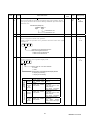
MITSUBISHI
General Purpose AC Servo
MELSERVO-J2S-S061
Built-In Positioning Function
Specifications and Instruction Manual
For Engineering Sample
MITSUBISHI
ELECTRIC
BCN-B11127-479*
Table of Contents
1. FUNCTION AND CONFIGURATION
1.1 Overview
1.2 Features
1.3 System configuration
2
2
3
3
2. WIRING DIAGRAM
5
3. TERMINALS
3.1Terminal blocks
3.2 Connection example
3.3 Power-on sequence
3.4 Signal explanations
3.5 Additional function devices
7
7
8
8
12
14
4. INTERFACES
16
5. AUTOMATIC OPERATION MODE
5.1 Positioning via point table with digital input
5.2 Positioning operation in accordance with point tables
5.3 Positioning operation via communication
5.4 Manual operation mode
5.5 Zeroing
18
18
22
23
24
26
6. DISPLAY AND OPERATION
6.1 Display flowchart
27
27
7. PARAMETERS
28
8. COMMUNICATIONS
8.1Configuration
8.2 Communication specifications
8.3 Protocol
8.4 Character codes
8.5 Error codes
8.6 Checksum
8.7 Time-out operation
8.8 Retry operation
8.9 Initialization
8.10 Communication procedure example
8.11 Command and data No. list
8.12 Detailed explanation of commands
47
47
49
50
52
53
53
54
54
55
55
56
66
REVISIONS
85
1
BCN-B11127-479*
1. FUNCTIONS AND CONFIGURATION
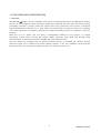
1.1 Overview
The MR-J2S- A-S061 AC servo amplifier with built-in positioning functions is the MR-J2S-A generalpurpose AC servo amplifier which incorporate single-axis positioning functions. These functions perform
positioning operation by merely setting the position data (target positions), motor speeds, acceleration
and deceleration time constants, etc. to point tables as if setting them in parameters. The servo amplifier
is the most appropriate to configure a program-free, simple positioning system or to simplify a system, for
example.
There are up to 31 points. You can choose a configuration suitable for your purpose, e.g. simple
positioning system using external I/O signals (DI/O), operation using DI/O and RS-422 serial
communication, or multi drop operation using RS-422 serial communication.
All servo motors are equipped with an absolute position encoder as standard. An absolute position
detection system can be configured by merely adding a battery to the servo amplifier. Once the home
position has been set, zeroing is not required at power on, alarm occurrence, etc.
2
BCN-B11127-479*
1.2 Features
(1) Up to 31 point tables
(2) Stopper type zeroing operation
(3) Point table output function
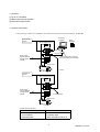
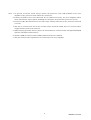
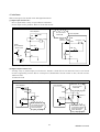
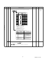
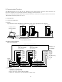
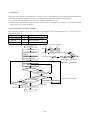
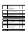
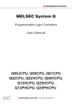
1.3 System configuration
1) Several (up to 32) servo amplifiers are connected with the personal computer by RS-422.
Personal
computer
External I/O
signals
Servo amplifier (axis 1)
Set-up
Software
CN1A CN1B
RS–232C
RS–422
Power supply
3-phase 200VAC
or single-phase
230VAC
RS–232C/RS-422 converter
(to be prepared by the customer)
CN2 CN3
Servo motor
RS–422
External I/O
signals
Servo amplifier (axis 2)
CN1A CN1B
Power supply
3-phase 200VAC
or single-phase
230VAC
CN2 CN3
To the next axis
Servo motor
Communication data
PC to Servo amplifier
- Positioning data to point table
- Control signals
- Parameter data
Servo amplifier to PC
- Status monitor
- Parameter data
- Alarm information and so on
3
BCN-B11127-479*
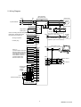
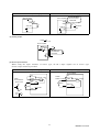
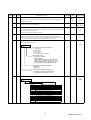
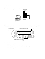
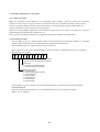
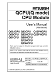
2) The following configuration uses external I/O signals. The external input signals are used to
control all signals (devices) that response delay is less than 15msec.
External I/O
signals
Servo amplifier
CN1A CN1B
Power supply
3-phase 200VAC
or single-phase
230VAC
CN2 CN3
Servo motor
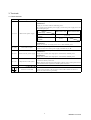
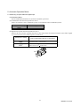
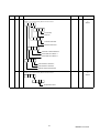
3) Function list
Contents
Description
Operation specification
- Positioning up to 31 point via point block #
- Setting at point block
Position command input
- Setting range for positioning: +/- 1 [um] to +/- 999.999 [um]
Point block # input
- Setting at point block
Command type
Speed command input
- Set at the point block for acc. / dec. time
- Parameter # 14 is for S-Curve acc. / dec. time constant
System
- Absolute value command with sign or incremental value command
Operation specification
- Positioning via RS-422(232C) communication
- Setting via RS-422(232C) communication
Position command input
- Setting range for positioning : +/- 1 [um] to +/- 999.999 [um]
Position data input
- Setting via RS-422(232C) communication
Speed command input
- Set the acc. / dec. time via RS-422(232C) communication
- Parameter # 14 is for S-Curve acc. / dec. time constant
System
- Absolute value command with sign or incremental value command
Operation mode
- Select the required ones from among 31 preset point blocks and
Automatic mode
perform operation in accordance with the set value
(Position block # input, Position data input)
Manual mode
Manual zeroing
- Jogging operation among preset jog speed via RS-422(232C)
JOG
communication or external input
- Stopper type zeroing
Stopper type zeroing
Capable set the zero address at parameter setting
- Absolute position detection system
- Backlash compensation
- External stroke limit function
Function on positioning control
- Software stroke limit function
- Teaching function
- Roll feeding function (equivalent)
4
BCN-B11127-479*
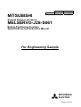
2. Wiring Diagram
NFB
Servo amplifier
MR-J2S-A-S061
MC
TE1
L1
L2
L3
3-phase 200VAC
Regenerative
brake option
Servo motor
U(Red)
U
V
W
V(White)
L11
L12
C TE2
B1
D
B2
(Green)
P
When connecting the external regenerative
brake option, always disconnect
10m(39.37inch) max.
the jumper from across P-D.
CN1A
COM 9
Zeroing completion
RA1
ZP 18
DOG 8
Proximity dog
SG 10
SG 20
CN2
Rough match
In position
Trouble
Ready
Upper limit setting
RA2
RA3
RA4
RA5
LG
External torque limit
Encoder
Encoder cable
(Available as option or to be fabricated)
Communication cable
CN1B
SON 15
LSP 16
LSN 17
MD0 7
DI0 5
DI1 14
ST1 8
ST2 9
SG 10
SG 20
VDD 3
COM 13
CPO 4
INP 6
ALM 18
RD 19
P15R 11
VC 2
Upper limit setting
Electromagnetic
brake
Emergency stop
To be shut off when servo on signal
switches off or alarm occurs.
10m(39.37inch) max.
Servo on
Forward rotation stroke end
Reverse rotation stroke end
Automatic/manual selection
Point table No. selection 1
Point table No. selection 2
Forward rotation start
Reverse rotation start
SM
W(Black)
CN3 (Available as option or to be fabricated)
CN3
4
3
14
13
MO1
LG
MO2
LG
Plate SD
A
A
Monitor output 1
10k
Monitor output 2
10k
1
TLA 12
SD Plate
2m(78.74inch) max.
5
BCN-B11127-479*
Note: 1. To prevent an electric shock, always connect the protective earth (PE) terminal of the servo
amplifier to the protective earth (PE) of the control box.
2. Connect the diode in the correct direction. If it is connected reversely, the servo amplifier will be
faulty and will not output signals, disabling the emergency stop and other protective circuits.
3. CN1A, CN1B, CN2 and CN3 have the same shape. Wrong connection of the connectors will lead
to a fault.
4. The sum of currents that flow in the external relays should be 80mA max. If it exceeds 80mA,
supply interface power from external.
5. When starting operation, always connect the forward/reverse rotation stroke end signal (LSN/LSP)
with SG. (Normally closed contacts)
6. Trouble (ALM) is connected with COM in normal alarm-free condition.
7. The pins with the same signal name are connected in the servo amplifier.
6
BCN-B11127-479*
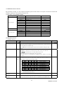
3. Terminals
3.1 Terminal blocks
Symbol
Signal
Description
Main circuit power input terminals
1) 200V Class
Supply L1, L2 and L3 with the following power.
For a single-phase 230VAC power supply, connect the power supply to L1 and
L2 and keep L3 open:
Servo amplifier
L1, L2, L3
Main circuit power supply
Power supply
MR-J2-10A to 70A
3-phase 200 to 230VAC,
50/60Hz
Single-phase 230VAC,
50/60Hz
MR-J2-100A to 700A
L1•L2•L3
L1•L2
Cannot be used for combination with the servo motor HC-SFS52•53.
2) 100V Class
Supply L1, L2 with the single-phase 100 to 120V 50/60Hz power.
U, V, W
L11, L21
P, C, D
Servo motor output
Control circuit power supply
Regenerative brake option
N
Servo motor power output terminalss
Connect to the servo motor power supply terminals (U, V, W).
Control circuit power input terminals
1) 200V Class
Supply L11 and L21 with single-phase 200-230VAC, 50/60Hz power.
2) 100V Class
Supply L11 and L21 with single-phase 100-120VAC, 50/60Hz power.
Regenerative brake option connection terminals
C and D are factory-connected.
When using the regenerative brake option, always remove wiring from across
P-D and connect the regenerative brake option across P-C.
Do not connect.
Protective earth (PE)
Ground terminal
Connect this terminal to the protective earth (PE) terminals of the servo
motor and control box for grounding.
7
BCN-B11127-479*
3.2 Connection example
Wire the power supply and main circuits as shown below. A no-fuse breaker (NFB) must be used with the
input cables of the power supply.
Design the circuit so that the servo on signal also turns off as soon as the power is shut off on detection of
alarm occurrence.
RA
Emergency
stop
OFF
ON
MC
MC
SK
(Note 1) Three-phase
200 to 230VAC
or
Single-Phase
230VAC
MC
NFB
L1 Servo amplifier
L2
L3
L11
L21
External
emergency stop
Servo on
RA
Trouble
EMG
SON
SG
VDD
COM
ALM
Note : For a single-phase 230VAC power supply, connect the power supply to L1
and L2 and keep L3 open.
3.3 Power-on sequence
(1) Power-on procedure
1) Always wire the power supply as shown in above Section 3.7.1 using the magnetic contactor with
the main circuit power supply (three-phase 200V: L1, L2, L3, single-phase 230V: L1, L2). Configure
up an external sequence to switch off the magnetic contactor as soon as an alarm occurs.
2) Switch on the control circuit power supply L11, L21 simultaneously with the main circuit power
supply or before switching on the main circuit power supply. If the main circuit power supply is not
on, the display shows the corresponding warning. However, by switching on the main circuit power
supply, the warning disappears and the servo amplifier will operate properly.
3) The servo amplifier can accept the servo-on signal (SON) about 1 second after the main circuit
power supply is switched on. Therefore, when SON is switched on simultaneously with the threephase power supply, the base circuit will switch on in about 1 second, and the ready signal (RD) will
switch on in further about 20ms, making the servo amplifier ready to operate.
4) When the reset signal (RES) is switched on, the base circuit is shut off and the servo motor shaft
coasts.
8
BCN-B11127-479*
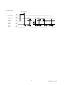
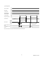
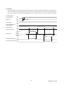
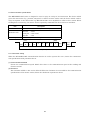
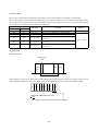
(2) Timing chart
SON accepted
(1s)
Power sypply
ON
OFF
Base circuit
ON
OFF
Servo on
(SON)
ON
OFF
Reset
(RES)
ON
OFF
Ready
(RD)
ON
OFF
10ms
60ms
10ms
60ms
20ms
20ms
10ms
10ms
20ms
10ms
9
BCN-B11127-479*
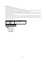
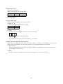
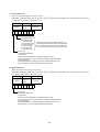
3.4 Signal explanations
1) CN1A
Signal Name
Symbol Pin No.
Description
I/O Division
Digital I/F power supply
input
COM
9
Used to input 24VDC±10% for input interface.
Driver power input terminal for digital interface.
COM of each connector is connected in the servo amplifier.
When using an external power supply, connect a power supply of
24VDC, 200mA or more to this terminal.
Open collector power
input
OPC
11
When using a manual pulse generator, supply 24VDC to this
terminal.
Common terminal for VDD and COM and isolated from LG.
Digital I/F common
DC15V power supply
Control common
Proximity dog
SG
10, 20
P15R
4
Used to output 15VDC. Power supply terminal for VC and TLA.
LG
1
Common terminal for VC, TLA, MO1, MO2 and P15R.
DOG
8
When terminals DOG-SG are shorted, the proximity dog signal is
detected. The polarity of dog detection input can be changed with the
parameter.
Parameter No.8
0
1
Zeroing completion
Shield
ZP
SD
Polarity of Proximity Dog Detection Input
DOG-SG are opened.
(initial value)
DOG-SG are shorted.
18
ZP-SG are connected on completion of zeroing.
In the absolute position system, ZP-SG are connected when the servo
amplifier is ready to operate but are disconnected if:
1) SON-SG are opened;
2) EMG-SG are opened;
3) RES-SG are shorted;
4) Alarm occurs;
5) Limit switch opens;
6) Zeroing has not been made after the purchase of the product;
7) Zeroing has not been made after the occurrence of absolute position
erasure (A. 25) or absolute position counter warning
(A. E3);
8) Zeroing has not been made after the changing of the electronic gear
value;
9) Zeroing has not been made after the absolute position system was
made valid; or
10) The ST1 coordinate system (000 in parameter No.1) has been
changed.
19
Empty
Plate
DI-1
DO-1
DI-1
DO-1
Connect one end of the shielded cable.
10
BCN-B11127-479*
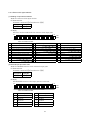
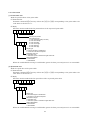
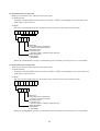
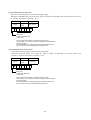
2) CN1B
Signal Name
Symbol Pin No.
Description
I/O Division
I/F Internal power
supply
VDD
3
Used to output 24V 10% to across VDD-COM.
When using this power supply for digital interface, connect it with
COM.
Permissible current: 80mA
Digital I/F power supply
input
COM
13
Used to input 24VDC 10% for input interface.
Driver power input terminal for digital interface.
COM of each connector is connected in the servo amplifier.
When using an external power supply, connect a power supply of
24VDC, 200mA or more to this terminal.
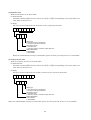
DC15V power supply
P15R
11
Used to output 15VDC to across P15R-LG. Used for VC/TLA power
supply.
Digital I/F Common
SG
10, 20
Control common
LG
1
Common terminal for VC, TLA, MO1, MO2 and P15R.
Servo on
SON
15
When SON-SG are shorted, the base circuit is switched on and the
servo amplifier is ready to operate.
When they are opened, the base circuit is shut off and the servo
motor coasts.
DI-1
Forward rotation stroke
end
LSP
16
To start operation, short LSP-SG or LSN-SG. When they are opened,
the servo motor is stopped suddenly and servo-locked.
DI-1
Reverse rotation stroke
end
LSN
17
24VDC common terminal for VDD, COM, etc. and isolated from LG.
Across
LSP-SG
Across
LSN-SG
1
1
0
1
1
0
0
0
DI-1
Operation
CCW direction
CW direction
Note. 0:Open,1:Short
Forward rotation start
ST1
8
This signal serves as a forward rotation start signal for the
incremental value command system.
In automatic operation mode, the servo motor rotates in the forward
rotation direction as soon as ST1-SG are shorted.
In zeroing mode, zeroing starts as soon as ST1-SG are shorted.
In jog operation mode, the servo motor rotates in the forward
rotation direction while ST1-SG are shorted.
Forward rotation denotes the direction in which the address is
incremented.
DI-1
This signal serves as a start signal for the absolute value command
system. In automatic operation mode, operation starts as soon as
ST1-SG are shorted.
In zeroing mode, zeroing starts as soon as ST1-SG are shorted.
In jog operation mode, the servo motor rotates in the forward
rotation direction while ST1-SG are shorted.
Forward rotation denotes the direction in which the address is
incremented.
Reverse rotation start
ST2
9
In automatic operation mode, the servo motor rotates in the reverse
rotation direction as soon as ST2-SG are shorted. (Incremental value
command only)
In jog operation mode, the servo motor rotates in the reverse
rotation direction while ST2-SG are shorted.
Reverse rotation denotes the direction in which the address is
decremented.
DI-1
11
BCN-B11127-479*
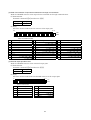
Signal Name
Automatic/manual
selection
Point table No. selection
Symbol Pin No.
Description
I/O Division
MDO
7
Short MDO-SG to choose the automatic operation mode, or open
them to choose the manual operation mode.
DI-1
DI0
DI1
5
14
The following table lists the point table numbers which may be
chosen by the combinations of DI0 and DI1:
DI-1
DI1
DI0
0
0
Manual zeroing
Selected Point Table No.
0
1
Point table No.1
1
0
Point table No.2
1
1
Point table No.3
Note: 0: DI1/DI0-SG open
1: DI1/DI0-SG shorted
Rough match
CPO
4
CPO-SG are connected when the remaining command distance falls
within the parameter-set rough match output range.
This signal is not output while the base circuit is off.
DO-1
In position
INP
6
INP-SG are connected when the droop pulses fall within the
parameter-set in-position range.
This signal is not output while the base circuit is off.
DO-1
Trouble
ALM
18
ALM-SG are disconnected when the protective circuit is activated to
shut off the base circuit at power off.
They are connected in normal condition at power off.
DO-1
Ready
RD
19
RS-SG are connected when the servo amplifier is ready to operate
without failure after servo-on.
DO-1
Override
VC
2
10 to 10V is applied to across VC-LG to limit the servo motor
speed. Apply 10[V] for 0[%] override, 0[V] for 100[%], or 10[V] for
200[%].
Analog
input
TLA
12
0 to 10V is applied to across TLA-LG to limit the servo motorgenerated torque.
Apply 0[V] for 0 torque or 10[V] for max. torque.
Analog
input
SD
Plate
External torque limit
Shield
Connect one end of the shielded cable.
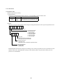
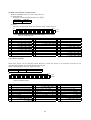
3) CN3
Description
I/O Division
Analog monitor 1
Signal Name
MO1
4
Used to output the data set in parameter No.17 to across MO1-LG in
terms of voltage. Resolution 8 bits
Analog
output
Analog monitor 2
MO2
14
Used to output the data set in parameter No.17 to across MO2-LG in
terms of voltage. Resolution 8 bits
Analog
output
SDP
9
SDN
19
RS-422 communication terminal
RS-422 and RS-232C functions cannot be used together.
Short "15" and "10" at the last axis.
RS-422 I/F
RS-232C I/F
Symbol Pin No.
RDP
5
RDN
15
TRE
10
RXD
2
TXD
12
RS-232C communication terminal
Use parameter No.16 for selection.
Monitor common
LG
1, 3,
11, 13
Monitoring common for control common
Ground
SD
Plate
Connect one end of the shielded cable.
12
BCN-B11127-479*
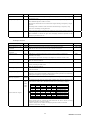
3.5 Additional function devices
By parameter setting, you can assign the signals given in this section to the pins of connectors CN1A and
CN1B, in addition to the signals in Section 3.2.
(1) Pins which accept different signals
Pin Type
Connector Pin No.
Input-only pins
I/O pin
Output-only pins
Device in Initial Status
Device Symbol
CN1B-5
Point table No. selection 1
CN1B-14
Point table No. selection 2
DI0
DI1
CN1A-8
Proximity dog
DOG
CN1B-15
Servo on
SON
CN1B-16
Forward rotation stroke end
LSP
CN1B-17
Reverse rotation stroke end
LSN
CN1B-7
Automatic/manual selection
MDO
CN1B-8
Forward rotation start
ST1
CN1B-9
Reverse rotation start
ST2
CN1A-19
Empty
CN1B-4
Rough match
CN1B-6
In position
INP
CN1B-18
Trouble
ALM
CN1B-19
Ready
RD
CN1A-18
Zeroing completion
ZP
CPO
(2) Assignable devices
1) Input devices
Device Name
Symbol
No assigned function
Description
I/O Division
No function is assigned.
Emergency stop
EMG
When EMG-SG are opened, the servo amplifier is placed in the emergency
stop status, the servo switches off, and the dynamic brake is operated to bring
the servo motor to a sudden stop.
Short EMG-SG in the emergency stop status to cancel the emergency stop
status.
DI-1
Alarm reset
RES
Short RES-SG to deactivate the alarm.
If RES-SG are shorted in no alarm status, the base circuit is not shut off.
Set 0
in parameter No. 55 to shut off the base circuit.
Some alarms cannot be deactivated by the reset signal.
Since this device is not designed for stopping, do not switch it on during
operation.
DI-1
Point table No. selection
DI2
DI3
DI4
Valid in the automatic mode.
The following table lists the point table numbers that may be chosen by the
combinations of DI0, DI1, DI2, DI3 and DI4:
DI4
DI3
DI2
DI1
DI0
Selected point table No.
0
0
0
0
0
Zeroing operation
0
0
0
0
1
Point table No.1
0
0
0
1
0
Point table No.2
0
0
0
1
1
Point table No.3
:
:
:
:
:
:
1
1
1
0
1
Point table No.28
1
1
1
0
1
Point table No.29
1
1
1
1
0
Point table No.30
1
1
1
1
1
Point table No.31
DI-1
Note:0: DI3/DI2/DI1/DI0-SG open
1: DI3/DI2/DI1/DI0-SG shorted
External torque limit
selection
TL0
Short TL0-SG to make external analog torque limit valid.
DI-1
Internal torque limit
selection
TL1
Open TL1-SG to make the torque limit value set in parameter No.28 (TL1)
valid, or short them to make the value set in parameter No.29 (TL2) valid.
DI-1
13
BCN-B11127-479*
Device Name
Symbol
Description
I/O Division
PC
Short PC-SG to switch the speed amplifier from proportional integral type to
proportional type.
DI-1
Temporary stop/Restart
STP
Short STP-SG during automatic operation to make a temporary stop.
Short STP-SG again to make a restart.
Shorting the forward/reverse rotation start signal during a temporary stop is
ignored.
Switching from automatic mode to manual mode during a temporary stop
clears the remaining moving distance.
During zeroing and jog operation, the temporary stop/restart input is ignored.
DI-1
Gain changing
CDP
Gain changing device
Short CDP-SG to switch the gain that changing condition depends on the
setting in parameter No. 68
DI-1
Description
I/O Division
Proportion control
2) Output devices
Device Name
Symbol
No assigned function
No function is assigned.
Electromagnetic brake
interlock
MBR
Used to output the interlock signal for electromagnetic brake.
MBR-SG are disconnected at servo-off or alarm occurrence.
DO-1
Dynamic brake
interlock
DBR
Dynamic brake interlock output device.
DO-1
Position range
POT
POT-SG are connected when the actual current position is within the
parameter-set range.
The output is open when zeroing is incomplete or the base circuit is off.
DO-1
Warning
WNG
WNG-SG are connected when warning occurs.
Open in normal condition.
DO-1
Battery warning
BWNG BWNG-SG are connected when the open battery cable warning (A. 92) or
battery warning (A. 9F) occurs.
Open in normal condition.
DO-1
Limiting torque
TLC
TLC-SG are connected when the internally or externally set torque limit
value is reached.
DO-1
Temporary stop
PUS
PUS-SG are connected when deceleration to a stop is started by the
temporary stop signal. PUS-SG is disconnected when operation is resumed by
making the temporary stop signal valid again.
DO-1
MEND-SG are connected when the in-position and rough match signal turned
on
The following table lists the point block numbers that may be chosen by the
combinations of PT0, PT1, PT2,TP3 and PT4 after positioning complete:
DO-1
Moving completion
MEND
PT0
PT1
PT2
PT3
PT4
Point table No. output
PT4
0
0
0
0
PT3
0
0
0
0
PT2
0
0
0
0
PT1
0
0
1
1
PT0
0
1
0
1
1
1
1
1
1
1
1
1
1
1
1
1
0
0
1
1
0
1
0
1
DO-1
Point block No.
Point block No.1
Point block No.2
Point block No.3
Point block No.28
Point block No.29
Point block No.30
Point block No.31
These signals will be turned off while Powered off, Servo off, In zeroing
operation and after zeroing complete.
It will be hold previous status if changed operation mode, in manual
operation and in fast zeroing
14
BCN-B11127-479*
(4) Device setting of control mode
Operation mode
Signal
Automatic/Manual
Point block No.
Automatic operation
Incremental
command
Absolute command
MD0
DI0
to
DI4
Forward rotation start
ST1
Reverse rotation start
ST2
ON
ON
1 to 31
1 to 31
Manual
drive
Manual
zeroing
OFF
ON
0
ON
5ms
5ms
(FWD. JOG)
5ms
(REV. JOG)
ON
5ms
Note: The start signal will respond within 3 ms.
Servo motor will be stopped and cleared moving remain distance when Automatic/Manual signal
changed in positioning.
15
BCN-B11127-479*
4. Interfaces
This section gives the details of the I/O signal interfaces.
(1) Digital input interface DI-1
Give a signal with a relay or open collector transistor.
Source input is also possible. Refer to (5) in this section.
For use of internal power supply
For use of external power supply
Servo amplifier
Do not connect
VDD-COM.
24VDC
Servo amplifier
VDD
R: Approx. 4.7k
COM
(Note)
For a transistor
24VDC
200mA or more
VDD
COM
R: Approx. 4.7k
SON, etc.
SON, etc.
Approx. 5mA
Switch
TR
Switch
SG
SG
VCES 1.0V
ICEO 100 A
Note: This also applies to the use of the external power supply.
(2) Digital output interface DO-1
A lamp, relay or photocoupler can be driven. Provide a diode (D) for an inductive load, or an inrush
current suppressing resister (R) for a lamp load. (Permissible current: 40mA or less, inrush current:
100mA or less)
1) Inductive load
For use of internal power supply
For use of external power supply
Servo amplifier
Servo amplifier
24VDC
VDD
VDD
COM
COM
Load
Load
ALM, etc.
ALM, etc.
SG
Do not connect
VDD-COM.
If the diode is not
connected as shown,
the servo amplifier
will be damaged.
27VDC or
less
SG
If the diode is not
connected as shown,
the servo amplifier
will be damaged.
16
BCN-B11127-479*
For use of internal power supply
For use of external power supply
Servo amplifier
24VDC
VDD
Servo amplifier
Do not connect
VDD-COM.
VDD
COM
COM
R
R
ALM, etc.
ALM, etc.
27VDC or
less
SG
(3) Analog output
Output 10V
Max. 1mA
Servo amplifier
10k
MO1
(MO2)
Reading in one or
A
both directions
1mA meter
LG
SD
(5) Source input interface
When using the input interface of source type, all DI-1 input signals are of source type.
Source output cannot be provided.
For use of internal power supply
For use of external power supply
Servo amplifier
Servo amplifier
SG
COM
(Note)
For a transistor
SG
COM
R: Approx. 4.7k
SON,
etc.
Approx. 5mA
Switch
Switch
TR
24VDC
200mA or more
R: Approx. 4.7k
SON, etc.
24VDC
VDD
VCES 1.0V
ICEO 100 A
Note: This also applies to the use of the external power supply.
17
BCN-B11127-479*
5. Automatic Operation Mode
5.1 Positioning via point table with digital input
(1) Parameter setting
Set the following parameters to perform automatic operation:
(a) Command mode selection (parameter No.0)
Select the absolute value command system or incremental value command system.
Parameter No. 0 Setting
Positioning System
0
Absolute value command
1
Incremental value command
(b) Operation system selection (parameter No.1)
Choose the servo motor rotation direction at the time when the forward rotation start (ST1) signal
or reverse rotation start (ST2) signal is switched on.
Parameter No. 1 Setting
Servo Motor Rotation Direction
When Forward Rotation Start (ST1) Is Switched On
0
CCW rotation with position data
CW rotation with
position data
1
CW rotation with position data
CCW rotation with
position data
CCW
CW
18
BCN-B11127-479*
(c) Feed length multiplication selection (parameter No.1)
Set the unit multiplication factor (STM) of position data. The actual moving distance is the result
of multiplying the entered position data by the unit multiplication factor.
Parameter No.1 Setting
Feed Length Multiplication STM [Times]
0
Position data
1
1
Position data
10
2
Position data
100
3
Position data
1000
(2) Point table
(a) Point table setting
Up to 31 point tables may be set. The following table lists what to set:
Name
Setting Range
Unit
Position data
999999 to 999999
Motor speed
0 to permissible speed
Acceleration
time constant
0 to 20000
ms
Set the acceleration time constant.
Set the time until the rated speed of the servo motor is reached.
Deceleration
time constant
0 to 20000
ms
Set the deceleration time constant.
Set the time until the servo motor running at rated speed comes to a stop.
ms
Set the dwell time.
Set "0" in the auxiliary function to make the dwell time invalid.
Set "1" in the auxiliary function and 0 in the dwell time to perform
continuous operation.
When the dwell time is set, the position command of the selected point
table is completed, and after the set dwell time has elapsed, the position
command of the next point table is started.
Dwell time
Auxiliary
function
0 to 20000
0•1
[
10SM
Description
In the absolute value command system, motion is made to the set address.
In the incremental value command system, motion is made over the set
distance.
m]
Use the parameter to select the incremental value command or absolute
value command.
A negative value cannot be set to the incremental value command.
r/min
Set the command speed of the servo motor for execution of positioning.
The setting should be equal to or less than the instantaneous permissible
speed of the servo motor.
Set the auxiliary function.
Set "1" to execute point tables consecutively without a stop.
0: Automatic operation is performed in accordance with a single point
table chosen.
1: Operation is performed in accordance with consecutive point tables
without a stop.
When a different rotation direction is set, smoothing zero (command
output) is confirmed and the rotation direction is then reversed.
Setting "1" in point table No.15 results in an error.
For full information, refer to Section 4.2.5.
19
BCN-B11127-479*
(b) Descriptions of auxiliary function
a) Auxiliary function setting “0”
Point block No.3
Point block No. 1
Point block No. 2
Servo motor
speed
Start signal
(ST1 or ST2)
b) Auxiliary function setting “1” and dwell time is “0”
Position block
No.3
Servo motor
speed
Position block
No. 1
0
Position block
No.2
Point block
Start signal
(ST1 or ST2)
Rough match
(CPO)
In position (INP)
No.1
ON
OFF
ON
OFF
ON
OFF
c) Auxiliary function setting “1” and dwell time is not “0”
Point table No. 3
Point block No.1
Point table No. 2
Servo motor
speed
Dwell
time
Point block
selection
Dwell
time
No.1
Start signal
(ST1 or ST2)
Rough match
(CPO)
In position
(INP)
20
BCN-B11127-479*
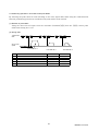
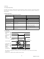
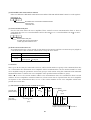
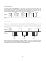
(3) Timing chart
Servo on (SON)
ON
OFF
Ready (RD)
ON
OFF
Trouble (ALM)
ON
OFF
Automatic/manual
selection (MDO)
ON
OFF
In position (INP)
ON
OFF
Rough match (CPO)
ON
OFF
Point table No.
Motor speed
No.1
Forward
rotation
0r/min
Reverse
rotation
Forward rotation start
(ST1)
ON
OFF
Reverse rotation start
(ST2) (Note)
ON
OFF
No.2
Point table No. 1
1.5ms or less
Point table No. 2
4ms or
more
Note: Reverse rotation start (ST2) is invalid for absolute value command system.
21
BCN-B11127-479*
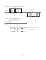
5.2 Positioning operation in accordance with point tables
By selecting the point table No. and switching on the start signal (ST1, ST2) using the communication
function, positioning operation in accordance with point tables can be started.
(1) Selection of point tables
Using the device forced output from the controller (command [9][2], data No. [6][0]), choose point
tables from among No.1 to 31
(2) Timing chart
Transmission
data
Servo motor
speed
1)
4)
5)
4)
5)
3)
4)
5)
5ms
Point table No. 2
No.
2)
Transmission Data
Point table No. 1
Point table No. 3
Command
Data No.
1)
Point table No.2 selection
[9] [2]
[6] [0]
2)
Point table No.1 selection
[9] [2]
[6] [0]
3)
Point table No.3 selection
[9] [2]
[6] [0]
4)
Forward rotation start (ST1) ON
[9] [2]
[6] [0]
5)
Forward rotation start (ST1) OFF
[9] [2]
[6] [0]
22
BCN-B11127-479*
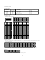
5.3 Positioning operation via communication
Positioning operation can be performed by changing the point table settings and making a start. For
example, positioning operation can be performed by writing the data of point table No.1, then specifying
point table No.1, and making a start.
Transmission data
1)
2)
3)
4)
5)
Servo motor speed
7)
6)
8)
5ms
Values set with transmission data 1) to 5) are used for operation.
No.
Transmission Data
Command
Data No.
[0] [1]
1)
Point table No.1 position data write
[C] [0]
2)
Point table No.1 speed
[C] [6]
[0] [1]
3)
Point table No.1 acceleration time constant
[C] [7]
[0] [1]
4)
Point table No.1 deceleration time constant
[C] [8]
[0] [1]
5)
Point table No.1 auxiliary function
[C] [B]
[0] [1]
6)
Point table No.1 selection
[9] [2]
[6] [0]
7)
Forward rotation start (ST1) ON
[9] [2]
[6] [0]
8)
Forward rotation start (ST1) OFF
[9] [2]
[6] [0]
23
BCN-B11127-479*
5.4 Manual operation mode
For machine adjustment, home position matching, etc., jog operation or a manual pulse generator may be
used to make a motion to any position.
5.4.1 Jog operation
(1) Setting
Set the input signal and parameters as follows according to the purpose of use. In this case, the point
table No. selection 1 to 5 signals (DI0 to DI4) are invalid:
Item
Setting Method
Manual operation mode selection
Description
Automatic/manual selection signal (MDO)
Open MDO-SG (OFF).
Servo motor rotation direction
Parameter No.1
Refer to (2) in this section.
Jog speed
Parameter No.13
Set the speed of the servo motor.
Point table No.1
Use the acceleration/deceleration
time constants in point table No.1.
Acceleration/deceleration time constant
(2) Servo motor rotation direction
Parameter No. 1 Setting
Servo Motor Rotation Direction
Forward Rotation Start (ST1) ON
Reverse Rotation Start (ST2) ON
0
CCW rotation
CW rotation
1
CW rotation
CCW rotation
ST1:ON
CCW
ST2:ON
CCW
CW
ST1:ON
CW
ST2:ON
Parameter No. 1
0
Parameter No. 1
1
24
BCN-B11127-479*
(3) Operation
By shorting ST1-SG, operation is performed under the conditions of the jog speed set in the parameter
and the acceleration and deceleration time constants in set point table No.1. For the rotation direction,
refer to (2) in this section. By shorting ST2-SG, the servo motor rotates in the reverse direction to ST1.
(4) Timing chart
Servo on (SON)
ON
OFF
Ready (RD)
ON
OFF
Trouble (ALM)
ON
OFF
Automatic/manual mode
selection (MDO)
ON
OFF
In position (INP)
ON
OFF
Rough match (CPO)
ON
OFF
Motor speed
100ms
Forward
rotation
0r/min
Reverse
rotation
Forward rotation start (ST1)
ON
OFF
Reverse rotation start (ST2)
ON
OFF
Forward rotation jog
Reverse rotation jog
25
BCN-B11127-479*
5.5 Zeroing
5.5.1 Stopper type zeroing
In stopper type zeroing, a machine part is pressed against a stopper or the like by jog operation, manual
pulse generator operation or the like to make a home position return and that position is defined as a
home position.
(1) Signals, parameters
Set the input signals and parameters as follows:
Item
Device/Parameter Used
Manual zeroing mode
selection
Stopper type zeroing
Description
Automatic/manual selection signal (MDO)
Short MDO-SG (ON).
Point table No. selection 1 (DI0)
Open DI0-SG (OFF).
Point table No. selection 2 (DI1)
Open DI1-SG (OFF).
Parameter No.8
3 : Stopper type zeroing is selected.
Zeroing direction
Parameter No.8
Refer to the parameter No.8
Zeroing speed
Parameter No.9
Set the speed till contact with the stopper.
Zeroing position data
Parameter No.42
Used to set the current position on completion
of zeroing
Stopper time
Parameter No.44
Time from when the part makes contact with
the stopper to when zeroing data is obtained to
output zeroing completion (ZP)
Stopper type zeroing torque
limit
Parameter No.45
Set the servo motor torque limit value for
execution of stopper type zeroing.
Zeroing acceleration time
constant
Point table No.1
Use the acceleration time constant of point
table No.1.
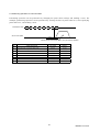
(2) Timing chart
Automatic/manual ON
mode selection
OFF
(MDO)
ON
In position (INP) OFF
ON
Rough match
OFF
(CPO)
ON
Zeroing
completion (ZP) OFF
Point table No.1
Acceleration time constant
Zeroing speed
Parameter No.9
Zero address
Parameter No. 42
Servo motor speed
5ms or less
Forward rotation
start (ST1)
Reverse rotation
start (ST2)
Limiting
torque (TLC)
Torque limit value
ON
OFF
ON
OFF
ON
OFF
Stopper
10ms or more
Stopper time
Parameter No. 44
Parameter No. 28
Parameter No. 45
Parameter No. 28
The address on completion of zeroing is the value automatically set in parameter No.42 (zeroing
position data).
Parameter No.14 (STC) will be disabled during zeroing.
26
BCN-B11127-479*
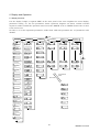
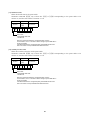
6. Display and Operation
6.1 Display flowchart
Use the display (5-digit, 7-segment LED) on the front panel of the servo amplifier for status display,
parameter setting, etc. Set the parameters before operation, diagnose an alarm, confirm external
sequences, and/or confirm the operation status. Press the "MODE" "UP" or "DOWN" button once to move
to the next screen.
To refer to or set the expansion parameters, make them valid with parameter No. 19 (parameter write
disable).
button
MODE
Status display
Diagnosis
Alarm
Point table
Basic
parameters
Expansion
parameters 3
Current position
[pulse]
Sequence
Current alarm
Point table No.1
Parameter No. 0
Parameter No. 50
Command position
[pulse]
External I/O
signal display
Last alarm
Point table No.2
Parameter No. 1
Parameter No. 51
Command remaining
distance [pulse]
Output signal
forced output
Second alarm in past
Test operation
Jog feed
Third alarm in past
Test operation
Positioning operation
Fourth alarm in past
Point table No. 30
Parameter No. 18
Parameter No. 89
Test operation
Motor-less operation
Fifth alarm in past
Point table No. 31
Parameter No. 19
Parameter No. 90
Test operation
Machine analyzer operation
Sixth alarm in past
Software version L
Parameter error No.
Cumulative feedback
pules [pulse]
Motor speed
[r/min]
Droop pulses
[pulse]
UP
DOWN
UP or DOWN
button
SET button
Regenerative load
ratio [%]
Software version H
Effective load ratio
[%]
Network I/F unit
S/W version L
Peak load ratio
[%]
Network I/F unit
S/W version H
Target position
Motor speed
Instantaneous torque
[%]
Acc. time
Motor series ID
Within one-revolution
position low [pulse]
Dec. time
Motor type ID
Within one-revolution
position high [pulse]
Dwell time
Encoder ID
ABS counter
[rev]
Auxiliary function
Load inertia moment
Ratio [times]
Bus voltage [V]
Communication status
27
BCN-B11127-479*
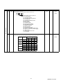
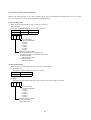
7. Parameters
For any parameter whose symbol is preceded by *, set the parameter value and switch power off once,
then switch it on again to make that parameter setting valid.
For details of the parameters, refer to the corresponding items.
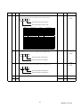
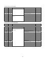
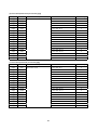
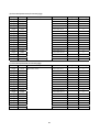
(1) Item list
Basic parameters
Class
No.
Symbol
Name and Function
Initial Value
0
*STY
Control mode, regenerative brake option selection
1
*FTY
Feeding function selection
0000
2
*OP1
Function selection 1
0002
Auto tuning
0105
Unit
Customer
Setting
0010
3
AUT
4
*CMX
Electronic gear numerator
1
5
*CDV
Electronic gear denominator
1
6
INP
Movement completion output range
100
pulse
7
PG1
Position loop gain 1
36
rad/s
8
ZTY
Zeroing type
0013
9
ZRF
Zeroing speed
500
r/min
10
CRF
Creep speed
10
r/min
11
ZST
Zero shift distance
0
12
CRP
Rough match output range
0
Um
10STM m
13
JOG
JOG speed
14
*STC
S-Curve acceleration/deceleration time constant
0
Ms
15
*SNO
Station number setting
0
station
16
*BPS
Alarm history clear
0000
17
MOD
For manufacture setting
0100
18
*DMD
Status display selection
0000
19
*BLK
Parameter block
0000
100
r/min
28
BCN-B11127-479*
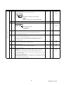
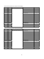
Expansion parameters
Class
No.
Symbol
Name and Function
Initial Value
Unit
20
*OP2
Function selection 2
0000
21
*OP3
Function selection 3
0000
22
*OP4
Function selection 4
0000
23
*SIC
Serial communications time-out selection
0
24
FFC
Feed forward gain
0
%
25
VCO
Override offset
0
mV
26
TLO
Torque limit offset
0
mV
27
*ENR
For manufacturer setting
4000
28
TL1
Internal torque limit 1
100
29
TL2
Internal torque limit 2
100
%
30
*BKC
Backlash compensation
0
pulse
31
MO1
Analog monitor ch1 offset
0
mV
32
MO2
Analog monitor ch2 offset
0
mV
33
MBR
Electromagnetic brake sequence output
100
ms
34
DG2
Ratio of load inertia moment to motor inertia moment
70
× 0.1 times
Sec
%
35
PG2
Position loop gain 2
35
rad/s
36
VG1
Speed loop gain 1
177
rad/s
37
VG2
Speed loop gain 2
817
rad/s
ms
38
VIC
Speed integral compensation
48
39
VDC
Speed differential compensation
980
40
OVA
For manufacture setting
0
41
DSS
42
*ZPS
Zeroing position data
0
0
10STM m
10STM m
43
DCT
Moving distance after proximity dog
1000
44
ZTM
Stopper type zeroing stopper time
100
ms
45
ZTT
Stopper type zeroing torque limit value
30
%
46
47
48
49
50
51
52
53
Customer
Setting
*LMP
Software limit +
*LMN
Software limit -
*LPP
Position range output address +
*LNP
Position range output address -
0
0
0
0
0
0
0
0
10STM m
10STM m
10STM m
10STM m
29
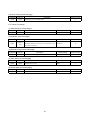
BCN-B11127-479*
Class
No.
Symbol
Name and Function
Initial Value
54
*OP5
Function selection 5
0000
55
*OP6
Function selection 6
0000
56
*OP7
Function selection 7
0000
57
*OP8
Function selection 8
0000
58
*OP9
Function selection 9
0000
59
*OPA
Function selection A
0000
For manufacturing setting
0000
61
NH1
Machine resonance suppression filter 1
0000
62
NH2
Machine resonance suppression filter 2
0000
60
Unit
63
LPF
Low-pass filter, adaptive vibration suppression control
64
GD2B
Ratio of load inertia moment to Servo motor inertia moment 2
70
× 0.1 time
65
PG2B
Position control gain 2 changing ratio
100
%
66
VG2B
Speed control gain 2 changing ratio
100
%
67
VICB
Speed integral compensation changing ratio
100
%
68
*CDP
Gain changing selection
0000
69
CDS Gain changing condition
CDT Gain changing time constant
10
For manufacturing setting
0
ms
70
71
VPI
0000
1
72
VLI
10000
pulse
73
ERZ
10
rev
74
ER2
10
rev
75
SRT
100
r/min
76
TRT
100
ms
100
ms
77
DBT
78
*DI0
Input/Output device selection (CN1A-19)
79
*DI1
Input device selection 1 (CN1A-19,8)
0009
80
*DI2
Input device selection 2 (CN1B-5,7)
080A
81
*DI3
Input device selection 3 (CN1B-8,9)
0706
82
*DI4
Input device selection 4 (CN1A-14,15)
020B
83
*DI5
Input device selection 5 (CN1B-16,17)
0504
84
*DI6
Input device selection 6 (Automatic ON)
0002
0000
0001
85
*DI7
Input device selection 7 (Automatic ON)
86
*DO1
Output device selection 1 (CN1A-18,19)
0005
87
*DO2
Output device selection 2 (CN1B-4,6)
0304
88
*DO3
Output device selection 3 (CN1B-18,19)
0102
89
Customer
Setting
0
For manufacturing setting
90
0
30
BCN-B11127-479*
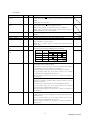
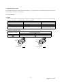
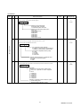
(2) Detail list
Class
No
0
Symbo
l
Name and function
*STY Control mode, Regenerative brake option selection
Use to select regenerative brake option.
0
Initial
Value
Unit
Setting Rnge
0000
0000h
to
0710h
0000
0000h
to
1013h
0002
0000h
to
1006h
0
Selection of command mode
0: Absolute value command
1: Incremental value command
Selection of regenerative brake option
0: Not used
1: Spare (do not set)
2: MR-RB032
3: MR-RB12
4: MR-RB32
5: MR-RB30
6: MR-RB50
7: Spare (do not set)
1
*FTY Feeding system selection
Used to set the feed length multiplication factor and
External pulse multiplication factor.
Basic parameters
0
ST1 coordinate system selection
0: Address is incremented in CCW direction
1: Address is incremented in CW direction
Feed length multiplication factor (STM)
0: 1 time
1: 10 times
2: 100 times
3: 1000 times
SON-off, EMG-off follow-up for absolute value
Command in incremental system
0: Invalid
1: Valid
2
*OP1 Function selection 1
Used to select the input filter and absolute position detection system.
0
0
Input filter
If external input signal causes chattering due
To noise, etc., input filter is used to suppress
it.
0: None
1: 0.888msec
2: 1.777msec
3: 2.666msec
4: 3.555msec
5: 4.444msec
6: 5.333msec
Selection of absolute position detection system
0: Incremental system
1: Absolute position detection system
31
BCN-B11127-479*
Class
No. Symbol
3
ATU
Name and Function
Initial Value
Auto tuning
Used to set the response level, etc. for execution of auto tuning.
0
Unit
Setting Range
0105
0001h
to
042Fh
1
1 to 65535
0
Auto tuning response level setting
Set
value
Basic parameters
1
2
3
4
5
6
7
8
9
A
B
C
D
E
F
Response
level
Machine resonance
Frequency guideline
15Hz
20Hz
25Hz
30Hz
35Hz
45Hz
55Hz
70Hz
85Hz
105Hz
130Hz
160Hz
200Hz
240Hz
300Hz
Low
Response
Middle
response
High
response
If the machine hunts or generates
large gear sound, decrease the
set value.
To improve performance, e.g.
shorten the settling time, increase
the set value.
Gain adjustment mode selection
(For more information, refer to Section 7.1.1.)
Set
Value
4
Gain adjustment
mode
Description
0
Interpolation mode
Fixes position control gain 1
1
Auto tuning mode 1
Ordinary auto tuning.
2
Auto tuning mode 2
Ordinary auto tuning.
Fixes the load inertia moment
ratio set in parameter No. 34.
Response level setting can be
changed.
3
Manual mode 1
Simple manual adjustment.
4
Manual mode 2
Manual adjustment of all
gains.
*CMX Electronic gear numerator
1
CMX
<
<20 .
Note: Set in the range of
20 CDV
1
CMX
If
<
<100 is exceeded, a parameter error will occur.
100 CDV
32
BCN-B11127-479*
Class
No. Symbol
5
Name and Function
Unit
1
*CDV Electronic gear denominator
Setting example
Initial Value
Setting Range
1 to 65535
Roll diameter: 50mm
Reduction ratio: 3/7
Number of pulses: 16384 pulses
Number of pulses (CMX)
16384
=
Moving distance (CDV )
50 × π× 3 7 × 1000
7168
9375π
7168
=
29452
Hence, set 7168 to CMX and 29452 to CDV.
=
Basic parameters
Note: When there is a fraction, perform a carry within the setting
range and round off that fraction.
6
INP
Movement completion output rang
Used to set the droop pulse range when the movement completion
(INP) signal is output.
100
pulse
0 to 10000
7
PG1
Position loop gain 1
Used to set the gain of position loop 1.
Increase the gain to improve tracking performance in response to the
position command.
35
rad/s
4 to 2000
8
ZTY Zeroing type
Used to set the zeroing system, zeroing direction and proximity dog input
polarity.
0
0000h
to
0117h
0013
3
Zeroing direction
0: Address increment direction
1: Address decrement direction
Proximity dog input polarity
0: Dog is detected when DOG-SG are opened
1: Dog is detected when DOG-SG are shorted
9
ZRF Zeroing speed
Used to set the motor speed for zeroing.
500
r/min
10
CRF Creep speed
Used to set the creep speed after proximity dog detection.
10
r/min
11
ZST Zero shift distance
Used to set the shift distance starting at the Z-phase pulse detection position
inside the encoder.
0
um
0
to
Max. speed
0
to
Max. speed
0
to
Max. speed
33
BCN-B11127-479*
Class
No. Symbol
Name and Function
12
CRP Rough match output range
Used to set the command remaining distance range where the rough match
(CPO) signal is output.
13
JOG Jog speed
Used to set the jog speed command.
14
Initial Value
0
Unit
10STM
m
Setting Range
0
to
65535
100
r/min
0
to
Max. speed
*STC S-pattern acceleration/deceleration time constant
Set when inserting an S-pattern time constant into the acceleration/deceleration
time constant of the point table.
This time constant is invalid for zeroing.
0
ms
0
to
100
15
*SNO RS-485 station number setting
Used to specify the station number for RS-485 multidrop communication.
Always set one station to one axis of servo amplifier. If one station number is set
to two or more stations, normal communication cannot be made.
0
station
0
to
31
16
*BPS Alarm history clear
Used to alarm history clear.
0000
0000h
to
1214h
0100
0000h
to
4B4Bh
RS-422/RS-232C baudrate selection
0: 9600 [bps]
1: 19200 [bps]
2: 38400 [bps]
3: 57600 [bps]
4: 4800 [bps] (for MR-DP60)
Alarm history clear
0: Invalid (not cleared)
1: Valid (cleared)
When alarm history clear is made valid, the
Alarm history is cleared at next power-on.
After the alarm history is cleared, the setting
is automatically made invalid (reset to 0)
Serial communication I/F selection
0: RS-232C
1: RS-422
Communication response delay time
0: Invalid, reply sent in less than 400us
1: Valid, reply sent in 888us or more
17
MOD For manufacturer setting
0
0
Setting
0
1
2
3
4
5
6
7
8
9
A
B
Analog Monitor Output Selection
Ch2
Ch1
Servo motor sped (+/- 8V/max. speed)
Generated torque (+/- 8V/max. torque)
Motor speed (+8V/max. torque)
Generated torque (+8V/max. torque)
Current command (+/- 8V/max. current command)
Speed command (+/- 8V/max. speed)
Droop pulses (+/-10V/128 pulses)
Droop pulses (+/- 10V/2048 pulses)
Droop pulses (+/- 10V/8192 pulses)
Droop pulses (+/- 10V/32768 pulses)
Droop pulses (+/- 10V/131072 pulses)
Bus voltage (+8V / 400V)
34
BCN-B11127-479*
Class No.
Symbol
18
*DMD
Name and Function
Initial Value
Status display selection
Used to select the status display shown at power-on .
Setting Range
0000h
to
1F1Fh
0000
0000h
to
FFFFh
0 0
Basic parameters
Unit
0000
Status display shown at power-on
00: Current position
01: Command position
02: Command remaining distance
03: Point table No.
04: Cumulative feedback pulses
05: Motor speed
06: Droop pulses
07: Override voltage
08: Limiting torque voltage
09: Regenerative load ratio
0A: Effective load ratio
0B: Peak load ratio
0C: Instantaneous torque
0D: Within one-revolution position (low)
0E: Within one-revolution position (high)
0F: ABS counter
10: Load inertia moment ratio
11: Bus voltage
19
*BLK
Parameter block
Used to select the reference and write ranges of the parameters.
Parameter No.
#20
#19
to
#53
Set Value
Operation
#00
to
#18
0000
(Initial value)
Reference
{
{
×
×
Write
{
{
×
×
Reference
×
{
×
×
Write
×
{
×
×
Reference
{
{
{
×
Write
{
{
×
×
Reference
{
{
{
×
Write
{
{
{
×
Reference
{
{
{
{
Write
{
{
{
{
000A
000B
000C
000E
#54
to
#90
35
BCN-B11127-479*
Class
No. Symbol
20
*OP2
Name and Function
Function selection 2
Used to select slight vibration suppression control.
0
Initial Value Unit
0000
Setting Range
0000h
to
1111h
0 0
Slight vibration suppression control selection
0: Invalid
1: Valid
Parameter No.2 must be “03
” or “04
” for activate this function.
21
*OP3
For manufacturer setting
0002
22
*OP4
Function selection 4
0000
0000h
to
0001h
0 0 0
Expansion parameters
H/W limit stop selection
0: Sudden stop
1: Slow stop
23
*SIC
Serial communication time-out selection
0
s
0 to 60
0
%
0 to 100
Used to choose the time-out period of communication protocol
0 means not time-out check.
24
FFC
25
VCO Override offset
Used to set the offset voltage to analog override.
0
mV
-999
to
999
26
TL0
0
mV
-999
to
999
4000
pulse
1
to
65535
27
Feed forward gain
Used to set the feed forward gain.
When it is set to 100%, droop pulses will not be generated in constant
speed operation. Note that sudden acceleration/deceleration will
increase overshoot.
Torque limit offset
Used to set the offset voltage to analog torque limit.
*ENR Encoder output pulses
Used to set the encoder pulses (A-phase, B-phase) output by the servo
amplifier.
Set the value 4 times greater than the A-phase or B-phase pulses.
You can use parameter No. 58 to choose the output pulse setting or output
division ratio setting.
The number of A/B-phase pulses actually output is 1/4 times greater than
the preset number of pulses.
The maximum output frequency is 1.3Mpps (after multiplication by 4). Use
this parameter within this range.
36
BCN-B11127-479*
Class
No. Symbol
Name and Function
Initial Value Unit
Setting Range
28
TL1
Internal torque limit 1
Used to limit servo motor-generated torque on the assumption that the
maximum torque is 100%. When 0 is set, torque is not produced.
This setting value will be 8V for torque monitor in monitor output.
100
%
0 to 100
29
TL2
Internal torque limit 2
Used to limit servo motor-generated torque on the assumption that the
maximum torque is 100%. When 0 is set, torque is not produced.
Made valid by switching on the internal torque limit selection signal.
100
%
0 to 100
30
*BKC Backlash compensation
Used to set the backlash compensation made when the command direction
is reversed.
This function compensates for the number of backlash pulses in the
opposite direction to the zeroing direction. In the absolute position
detection system, this function compensates for the backlash pulse
count in the direction opposite to the operating direction at power-on.
0
pulse
0 to 1000
31
MO1
Analog monitor ch1 offset
Used to set the offset voltage of the analog monitor ch1 output (MO1).
0
mV
-999 to 999
32
MO2
Analog monitor ch2 offset
Used to set the offset voltage of the analog monitor ch2 output (MO2)
0
mV
-999 to 999
33
MBR
Electromagnetic brake sequence output
Used to set the delay time between when the electromagnetic brake
interlock signal (MBR) switches off and when the base circuit is shut
off.
100
ms
0 to 1000
34
GD2
Ratio of load inertia moment to motor inertia moment:
Used to set the ratio of the load inertia moment to the servo motor
shaft inertia moment.
When auto tuning is selected, the result of auto tuning is
automatically set.
70
×0.1
times
0 to 3000
35
PG2
Position loop gain 2
Used to set the gain of the position loop.
Set this parameter to increase the position response level to load
disturbance. Higher setting increases the response level but is liable
to generate vibration and/or noise.
When auto tuning is selected, the result of auto tuning is
automatically set.
35
rad/s
1 to 1000
36
VG1
Speed loop gain 1
Normally this parameter setting need not be changed.
Higher setting increases the response level but is liable to generate
vibration and/or noise.
When auto tuning is selected, the result of auto tuning is
automatically set.
177
rad/s
20 to 8000
37
VG2
Speed loop gain 2
Set this parameter when vibration occurs on machines of low rigidity
or large backlash.
Higher setting increases the response level but is liable to generate
vibration and/or noise.
When auto tuning is selected, the result of auto tuning is
automatically set.
817
rad/s
20 to 20000
38
VIC
Speed integral compensation
Used to set the integral time constant of the speed loop.
When auto tuning is selected, the result of auto tuning is
automatically set.
48
ms
1 to 1000
39
VDC
Speed differential compensation
Used to set the differential compensation.
Made valid when the proportion control signal is switched on.
980
0 to 1000
37
BCN-B11127-479*
Class
No.
Symbol
40
OVA
Name and Function
43
Setting Range
0
For manufacturing setting
41
42
Initial Value Unit
0
*ZPS Zeroing position data
Used to set the current position on completion of zeroing.
DCT
0
10S
m
−32768
to
32767
10S
m
0 to 65535
TM
Moving distance after proximity dog
Used to set the moving distance after proximity dog in count type zeroing.
1000
TM
44
ZTM
Stopper type zeroing stopper time
In stopper type zeroing, used to set the time from when the machine part
is pressed against the stopper and the torque limit set in parameter
No.45(ZTT) is reached to when the home position is set.
100
ms
5 to 1000
45
ZTT
Stopper type zeroing torque limit
Used to set the torque limit value relative to the max. torque in [%] in
stopper type zeroing.
15
%
1 to 100
10ST
m
999999
to
999999
10ST
m
999999
to
999999
10ST
m
999999
to
999999
46
47
LMP Software limit
Used to set the address increment side software stroke limit. The software
limit is made invalid if this value is the same as in "software limit ".
Set the same sign to parameters No.46 and 47. Setting of different signs will
result in a parameter error.
0
M
Set address:
Upper 3 Lower 3
digits
digits
Parameter No. 47
Parameter No. 46
48
49
LMN Software limit
Used to set the address decrement side software stroke limit. The software
limit is made invalid if this value is the same as in "software limit ".
Set the same sign to parameters No.48 and 49. Setting of different signs will
result in a parameter error.
0
M
Set address:
Upper 3 Lower 3
digits
digits
Parameter No. 49
Parameter No. 48
50
51
LPP Position range output address
Used to set the address increment side position range output address. Set the
same sign to parameters No.50 and 51. Setting of different signs will result in
a parameter error.
0
M
Set address:
Upper 3 Lower 3
digits
digits
Parameter No. 51
Parameter No. 50
38
BCN-B11127-479*
No. Symbol
52
53
Name and Function
LNP Position range output address
Used to set the address decrement side position range output address. Set the
same sign to parameters No.52 and 53. Setting of different signs will result in a
parameter error.
Initial
Value
0
Unit
10STM
m
Setting Range
999999
to
999999
Set address:
Upper 3
digits
Lower 3
digits
Parameter No. 53
Parameter No. 52
54
*OP5 For manufacturer setting
0000
55
*OP6 Optional function 6
Servo on response in alarm reset operation.
Used to select the operation to be performed when the alarm reset signal
switches on.
0000
0000h
to
1111h
0000
0000h
to
1111h
0
0 0
Operation to be performed when the
alarm reset signal switches on
0: Base circuit not switched off
1: Base circuit switched off
*OP7 Optional function 7
Used to select the current position display mode.
0 0
Electric gear cal. error clear selection
0: Invalid
1: Valid
Current position / Commanded position display selection
0: Display of positioning
1: Display of role feeding
Item
Automatic
operation mode
56
Manual operation
Class
Current
position
Comman
ded
position
Current
position
Comman
ded
position
Display of positioning
Display of role feeding
Display actual position
from machine home
position
Display
commanded
position from machine
home position
Display
commanded
position from machine
home position
Display
commanded
position from machine
home position
Display actual position from
power on
Display target position in
stop motion.
Count start from 0 at start
signal turned on.
And display commanded
position till target position
Display target position in
stop motion.
Count start from 0 at start
signal turned on.
And display commanded
position till target position
Display target position in
stop motion.
And
display
selected
position data at start signal
turned on.
39
BCN-B11127-479*
Expansion parameters
Class
No. Symbol
57
Initial
Value
Name and Function
*OP8 Function selection 8
Used to select the protocol of serial communication.
0
Unit
Setting Range
0000
0000h
to
1112h
0000
0000h
to
1101h
0000
0000h
to
0211h
0
Protocol checksum selection
0: Yes (checksum added)
1: No (checksum not added)
Protocol checksum selection
0: With station numbers
1: No station numbers
58
*OP9 Function selection 9
Use to select the command pulse rotation direction, encoder output pulse
direction and encoder pulse output setting.
0
Servo motor rotation direction changing
Changes the servo motor rotation
direction for the input pulse train.
Set value
Servo motor rotation direction
At forward rotation
At reverse rotation
pulse input (Note)
pulse input (Note)
0
CCW
CW
1
CW
CC W
Encoder pulse output phase changing
Changes the phases of A, B-phase encoder pulses output .
Servo motor rotation direction
Set value
0
1
CCW
CW
A phase
A phase
B phase
B phase
A phase
A phase
B phase
B phase
Encoder output pulse setting selection (refer to parameter No. 27)
0: Output pulse setting
1: Division ratio setting
59
*OPA Function selection A
Alarm code output function selection
0 0 0
Alarm code output
0: Invalid
1: Valid
60
For manufacture setting
0000
40
BCN-B11127-479*
Class
No. Symbol
61
NH1
Initial
value
Name and function
Machine resonance suppression filter 1
Used to selection the machine resonance suppression filter.
Unit
Setting range
0000
.0000h
to
031Fh
0000
0000h
to
031Fh
0
Notch frequency selection
Setting Frequency Setting Frequency Setting Frequency Setting Frequency
value
value
value
value
00
Invalid
08
562.5
10
281.3
18
187.5
01
4500
09
500
11
264.7
19
180
02
2250
0A
450
12
250
1A
173.1
03
1500
0B
409.1
13
236.8
1B
166.7
04
1125
0C
375
14
225
1C
160.1
05
900
0D
346.2
15
214.3
1D
155.2
06
750
0E
321.4
16
204.5
1E
150
07
642.9
0F
300
17
195.7
1F
145.2
Notch depth selection
62
NH2
Setting
value
Depth
Gain
0
Deep
40dB
1
to
14dB
2
3
Shallow
8dB
4dB
Machine resonance suppression filter 2
Used to set the machine resonance suppression filter.
0
Notch frequency
Same setting as in parameter No. 61
However, you need not set "00" if you have
set adaptive vibration suppression control to
be "valid" or "held".
Notch depth
Same setting as in parameter No. 61
41
BCN-B11127-479*
Class
No. Symbol
63
LPF
Initial
value
Name and function
Low-pass filter/adaptive vibration suppression control
Used to selection the low-pass filter and adaptive vibration suppression
control.
Unit
0000
Setting range
0000h
to
1217h
0
Low-pass filter selection
0: Valid (Automatic adjustment)
1: Invalid
VG2 setting 10
2 (1 GD2 setting 0.1)
bandwidth filter is set automatically.
When you choose "valid",
[H z]
Adaptive vibration suppression control selection
Choosing "valid" or "held" in adaptive vibration
suppression control selection makes the machine
resonance control filter 1 (parameter No. 58) invalid.
0: Invalid
1: Valid
Machine resonance frequency is always detected
and the filter is generated in response to resonance to
suppress machine vibration.
2: Held
The characteristics of the filter generated so far are held,
and detection of machine resonance is stopped.
Adaptive vibration suppression control sensitivity selection
Used to set the sensitivity of machine resonance detection.
0: Normal
1: Large sensitivity
64
GD2B Ratio of load inertia moment to servo motor inertia moment 2
Used to set the ratio of load inertia moment to servo motor inertia
moment when gain changing is valid.
70
0.1
times
0
to
3000
65
PG2B
100
%
10
to
200
66
VG2B Speed control gain 2 changing ratio
Used to set the ratio of changing the speed control gain 2 when gain
changing is valid.
Made valid when auto tuning is invalid.
100
%
10
to
200
67
VICB
Speed integral compensation changing ratio
Used to set the ratio of changing the speed integral compensation when
gain changing is valid. Made valid when auto tuning is invalid.
100
%
50
68
*CDP
Gain changing selection
0000
Position control gain 2 changing ratio
Used to set the ratio of changing the position control gain 2 when gain
changing is valid.
Made valid when auto tuning is invalid.
Used to select the gain changing condition.
to
1000
0000h
to
0004h
0 0 0
Gain changing selection
Gains are changed in accordance with the settings
of parameters No. 64 to 67 under any of the following
conditions:
0: Invalid
1: Gain changing (CDP) signal is ON
2: Command frequency is equal to higher than
parameter No. 69 setting
3: Droop pulse value is equal to higher than
parameter No. 69 setting
4: Servo motor speed is equal to higher than
parameter No. 69 setting
42
BCN-B11127-479*
Class
No. Symbol
Initial
value
Name and function
Unit
Setting range
69
CDS
Gain changing condition
Used to set the value of gain changing condition (command frequency,
droop pulses, servo motor speed) selected in parameter No. 68.The set
value unit changes with the changing condition item.
10
kpps
pulse
r/min
0
to
9999
70
CDT
Gain changing time constant
Used to set the time constant at which the gains will change in response
to the conditions set in parameters No. 68 and 69.
1
ms
0
to
100
71
VPI
72
VLI
10000
73
ERZ
10
74
ER2
10
75
SRT
100
76
TRT
100
77
DBT
100
78
*DI0
For manufacture setting
100
Input / Output device selection
Used to select the CN1A-19 pin to output or input device
0000
0000h
to
0001h
0009
0000h
to
1F1Fh
0 0 0
CN1A-19 pin
0: Output device
1: Input device
79
*DI1
Input device selection 1
Used to select the function of CN1A-8 pin and CN1A-19 pin
Set to the function of CN1A-8 pin
Set to the function of CN1A-19 pin
Setting
00
01
02
03
04
05
06
07
08
09
0A
0B
0C
0D
0E
0F
10
11
12
13
14
15
16
Input function
No function
Forced stop
Servo on
Alarm reset
FWD stroke limit
REV stroke limit
FWD rotation start
REV rotation start
Auto. / Manu.
Point table # selection 1
Point table # selection 2
Point table # selection 3
Point table # selection 4
External torque limit
Internal torque limit
Proportional control
Temp. stop / Restart
Point table # selection 5
Setting
17
18
19
1A
1B
1C
1D
1E
1F
20
21
22
23
34
25
26
27
28
29
2A
2B
2C
2D
Input function
Gain changing selection
43
BCN-B11127-479*
Class
No. Symbol
80
Name and Function
*DI2 Input device selection 2
Used to select the function of CN1B-5 pin and CN1B-7 pin
Initial
Value
Unit
Setting Range
080A
0000h
to
1F1Fh
0706
0000h
to
1F1Fh
020B
0000h
to
1F1Fh
0504
0000h
to
1F1F
Set to the function of CN1B-5 pin
Set to the function of CN1B-7 pin
81
*DI3 Input device selection 3
Used to select the function of CN1B-8 pin and CN1B-9 pin
Set to the function of CN1B-8 pin
Set to the function of CN1B-9 pin
82
*DI4
Input device selection 4
Used to select the function of CN1B-14 pin and CN1B-15 pin
Set to the function of CN1B-14 pin
Set to the function of CN1B-15 pin
83
*DI5
Input device selection 5
Used to select the function of CN1B-16 pin and CN1B-17 pin
Set to the function of CN1B-16 pin
Set to the function of CN1B-17 pin
44
BCN-B11127-479*
Class
No.
Symbol
84
*DI6
Name and Function
Input device selection 6
Used to set automatically ON of function device
Initial Value Unit
Setting Range
0002
0000h
to
FFFFh
0000
0000h
to
FFFFh
Forced stop
Servo on
Forward stroke limit
Reverse stroke limit
Automatic / Manual selection
Point table No. selection 1
Point table No. selection 2
Point table No. selection 3
Point table No. selection 4
External torque limit selection
85
*DI7
Input device selection 7
Used to set automatically ON of function device
Proportional control
45
BCN-B11127-479*
Class
No.
Symbol
86
*DO1
Name and Function
Initial Value Unit
Output device selection 1
Used to select the function of CN1A-18 pin and CN1A-19 pin
Setting Range
0005
0000h
to
1F1Fh
0304
0000h
to
0F0Fh
0102
0000h
to
0F0Fh
Set to the function of CN1A-18 pin
Set to the function of CN1A-19 pin
Setting
00
01
02
03
04
05
06
07
08
09
0A
0B
0C
0D
0E
0F
10
11
12
13
14
87
*DO2
Input function
No function
Ready
Trouble
In position
Rough mach
Zeroing complete
Electro magnetic brake
Dynamic brake interlock
Position range output
Warning output
Battery warning
In torque limit
In temporally stop
Moving complete
Point table # output 1
Point table # output 2
Point table # output 3
Point table # output 4
Point table # output 5
Setting
15
16
17
18
19
1A
1B
1C
1D
1E
1F
20
21
22
23
24
25
26
27
28
29
Input function
Output device selection 2
Used to select the function of CN1B-6 pin and CN1B-4 pin
Set to the function of CN1B-4 pin
Set to the function of CN1B-6 pin
88
*DO3
Output device selection 3
Used to select the function of CN1B-18 pin and CN1B-19 pin
Set to the function of CN1B-18 pin
Set to the function of CN1B-19 pin
89
For manufacture setting
0
90
0
46
BCN-B11127-479*
8. Communication Functions
The MR-J2S-A-S061 has the RS-422 and RS-232C serial communication functions. These functions can
be used to perform servo operation, parameter changing, monitor function, etc.
However, the RS-422 and RS-232C communication functions cannot be used together. Select between RS422 and RS-232C with parameter No.16.
8.1 Configuration
8.1.1 RS-422 configuration
(1) Outline
Up to 32 axes of servo amplifiers from stations 0 to 31 can be operated on the same bus.
Servo amplifier
Servo amplifier
Servo amplifier
MITSUBISHI
MITSUBISHI
MITSUBISHI
Controller such as
personal computer
CHARGE
RS-232C/
RS-422
converter
CHARGE
To
CN3
Axis 1 (Station 0)
To
CN3
Axis 2 (Station 1)
CHARGE
To
CN3
Axis 32 (Station 31)
RS-422
Unavailable as option.
To be prepared by customer.
(2) Cable connection diagram
Wire as shown below:
(Note 3) 30m(1181.10inch) max.
(Note 1)
Axis 1 servo amplifier
CN3 connector
(Note 1)
Axis 2 servo amplifier
CN3 connector
Plate SD
RS-422
output unit
Plate SD
(Note 1)
Axis 32 (last axis)
servo amplifier
CN3 connector
Plate SD
9
SDP
9
SDP
9
SDP
19
SDN
19
SDN
19
SDN
5
RDP
5
RDP
5
RDP
15
RDN
15
RDN
15
RDN
10
TRE
10
TRE
10
TRE (Note 2)
11
LG
11
LG
11
LG
1
LG
1
LG
1
LG
RDP
RDN
SDP
SDN
GND
GND
Note: 1. 3M's CN3 connector
Connector: 10120-3000VE
Shell kit: 10320-52F0-008
2. In the last axis, connect TRE and RDN.
3. 30m(1181.10inch) max. in environment of little noise.
47
8.1.2 RS-232C configuration
(1) Outline
A single axis of servo amplifier is operated.
Servo amplifier
MR-J2S-A-S061
MITSUBISHI
CHARGE
To CN3
RS-232C
Controller such as
personal computer
(2) Cable connection diagram
Wire as shown below. The communication cable for connection with the personal computer (MRCPCATCBL3M) is available.
Personal computer
connector D-SUB25 (socket)
(Note 3) 15m(590.55inch) max.
(Note 4)
(Note 1)
Servo amplifier
CN3 connector
Plate FG
TXD
3
2 RXD
RXD
2
12 TXD
GND 5
11 GND
1 GND
RTS
7
CTS
8
DSR
6
DTR
4
SD 2
RD 3
SG 7
CN3 connector 2
CN3 connector 1
CN3 connector 12
CN3 connector 11
RS 4
D-SUB29 (socket) for PC-98 CS 5
compatible controller
(Note 2)
Note: 1. 3M's CN3 connector
Connector: 1020-3000VE
Shell kit: 10320-52F0-008
2. For the PC-98 series. The PC-98 series also has the half-pitch type.
3. 15m (590.55inch) max. in environment of little noise.
4. For the PC-AT compatible.
48
RXD
GND
TXD
GND
8.2 Communication specifications
The MELSERVO-J2S series is designed to send a reply on receipt of an instruction. The device which
gives this instruction (e.g. personal computer) is called a master station and the device which sends a
reply in response to the instruction (e.g. MR-J2S-A-S061 servo amplifier) is called a slave station. When
fetching data successively, the master station repeatedly commands the slave station to send data.
Item
Baudrate
Description
9.6k/19.2k/38.4k/57.6k asynchronous system
Start bit : 1 bit
Data bit : 8 bits
Transfer code
Parity bit : 1 bit (even)
Stop bit : 1 bit
Transfer protocol Character system, half-duplex communication system
(LSB)
Start
0
(MSB)
1
2
3
4
5
6
7
Parity
Stop
Next
start
Data
1 frame (11 bits)
8.2.1 Parameter setting
When the RS-422/RS-232C communication function is used to operate the servo, choose the communication specifications with parameter No.16.
(1) Communication baudrate
Choose the communication speed. Match this value to the communication speed of the sending end
(master station).
(2) Checksum
The checksum added to data can be deleted. When the checksum is not needed for the communication
specifications of the master station, delete the checksum at parameter No.57
49
(3) RS-422/RS-232C serial interface selection
Select the RS-422 or RS-232C communication standard. RS-422 and RS-232C cannot be used together.
Parameter No. 16
−
− −
RS-422/RS-232C communication standard selection
0: RS-422 used
1: RS-232C used
(4) Communication delay time
Set the time from when the servo amplifier (slave station) receives communication data to when it
sends back data. Set "0" to send back data in less than 888 s or "1" to send back data in 888 s or more.
Parameter No. 16
− − −
Communication delay time
0: Invalid, reply sent in less than 888µs
1: Valid, reply sent in 888µs or more
(5) Serial communication time-out
No communication for a given period of time between the master and slave stations may be judged as
a communication cable or master station fault to stop the servo motor.
Setting
Description
0
No time-out check
Time-out check period setting
1 to 60
Check period
setting (S)
8.3 Protocol
Since up to 32 axes may be connected to the bus, add a station number or group to the command, data No.,
etc. to determine the destination servo amplifier of data communication. Set the station number to each
servo amplifier using the parameter and set the group to each station using the communication command.
Transmission data is valid for the servo amplifier of the specified station number or group.
When " " is set as the station number added to the transmission data, the transmission data is made
valid for all servo amplifiers connected. However, when return data is required from the servo amplifier
in response to the transmission data, set "0" to the station number of the servo amplifier which must
provide the return data.
Servo side
(Slave station)
10 frames (data)
S
T
X
Data
No.
Data
E
T
X
Check
sum
Station number
or
group
S
T
X
Station number
or
group
Error code
Controller side
(Master station)
S
O
H
Command
(1) Transmission of data from the controller to the servo
E
T
X
Check
sum
6 frames
Positive response: Error code A
Negative response: Error code other than A
50
(2) Transmission of data request from the controller to the servo
S
O
H
S
T
X
Data
No.
E
T
X
Check
sum
Station number
or
group
S
T
X
Station number
or
group
Servo side
Error code
Controller side
Command
10 frames
Data
E
T
X
Check
sum
6 frames (data)
(3) Recovery of communication status by time-out
Controller side
E
O
T
EOT causes the servo to return to
the receive neutral status.
Servo side
Data: Choose the data length from among 4, 8, 12 and 16 frames (data length depends on the command).
Data
4 frames
or
Data
8 frames
51
or 12 frames or 16 frames
8.4 Character codes
(1) Control codes
Personal Computer Terminal Key Operation
(General)
Code Name
Hexadecimal
(ASCII code)
Description
SOH
STX
ETX
EOT
01H
02H
03H
04H
start of head
start of text
end of text
end of transmission
ctrl
ctrl
ctrl
ctrl
A
B
C
D
(2) Codes for data
JIS8 unit codes are used.
b8 to
b5
b8
0
0
0
0
0
0
0
0
b7
0
0
0
0
1
1
1
1
b6
0
0
1
1
0
0
1
1
b5
0
1
0
1
0
1
0
1
0
1
2
3
4
5
6
7
C
b4
b3
b2
b1
0
0
0
0
0
NUL
DLE
Space
0
@
P
`
p
0
0
0
1
1
SOH
DC1
!
1
A
Q
a
q
0
0
1
0
2
STX
DC2
"
2
B
R
b
r
0
0
1
1
3
ETX
DC3
#
3
C
S
c
s
0
1
0
0
4
$
4
D
T
d
t
0
1
0
1
5
%
5
E
U
e
u
0
1
1
0
6
&
6
F
V
f
v
0
1
1
1
7
'
7
G
W
g
w
R
1
0
0
0
8
(
8
H
X
h
x
1
0
0
1
9
)
9
I
Y
i
y
1
0
1
0
10
:
J
Z
j
z
1
0
1
1
11
;
K
[
k
{
1
1
0
0
12
,
L
¥
l
|
1
1
0
1
13
-
M
]
m
}
1
1
1
0
14
.
N
^
n
¯
1
1
1
1
15
/
O
_
o
DEL
?
(3) Station numbers
You may set 32 station numbers from station 0 to station 31 and the JIS8 unit codes are used to
specify the stations.
Station number
0
1
2
3
4
5
6
7
8
9
10
11
12
13
14
15
JIS8 code
0
1
2
3
4
5
6
7
8
9
A
B
C
D
E
F
Station number
16
17
18
19
20
21
22
23
24
25
26
27
28
29
30
31
JIS8 code
G
H
I
J
K
L
M
N
O
P
Q
R
S
T
U
V
For example, "30H" is transmitted in hexadecimal when the station number is "0" (first axis).
(4) Group
Group
a
b
c
d
e
f
JIS8 code
a
b
c
d
e
f
All group
For example, "61H" is transmitted in hexadecimal for group a.
52
8.5 Error codes
Error codes are used in the following cases and an error code of single-code length is transmitted.
On receipt of data from the master station, the slave station sends the error code corresponding to that
data to the master station. The code transmitted in uppercase indicates that the servo is normal and the
one in lowercase indicates that an alarm has occurred.
Error Code
Error Name
Description
Servo normal
Servo alarm
[A]
[a]
Normal operation
Data transmitted was processed properly.
[B]
[b]
Parity error
Parity error occurred in the transmitted data.
[C]
[c]
Checksum error
Checksum error occurred in the transmitted data.
[D]
[d]
Character error
Character not existing in the specifications was
transmitted.
[E]
[e]
Command error
Command not existing in the specifications was
transmitted.
[F]
[f]
Data No. error
Data No. not existing in the specifications was
transmitted.
Remarks
Positive response
Negative response
8.6 Checksum
Checksum range
Station number
or
group
STX or
SOH
ETX
Check
Checksum range
The checksum is sent as a JIS8-coded hexadecimal code representing the lower two digits of the sum of
JIS8-coded hexadecimal values up to ETX, with the exception of the first control code (STX or SOH).
S
T
X
[0] [A] [1] [2] [5] [F]
E
T
X
[5] [2]
02H 30H 41H 31H 32H 35H 46H 03H
30H 41H 31H 32H 35H 46H 03H
152H
Lower 2 digits 52 is sent after conversion into ASCII code [5][2].
53
8.7 Time-out operation
The master station transmits EOT when the slave station does not start reply operation (STX is not
received) 300[ms] after the master station has ended communication operation. 100[ms] after that, the
master station retransmits the message. Time-out occurs if the slave station does not answer after the
master station has performed the above operation three times. (Communication error)
100ms
300ms
Message
E
O
T
Message
Message
Controller
(Master station)
100ms
300ms
E
O
T
300ms
Time-out
Message
100ms
300ms
E
O
T
Servo
(Slave station)
8.8 Retry operation
Servo
(Slave station)
S
T
X
Station number
or
group
Communication error
Message
Message
Controller
(Master station)
Message
When a fault occurs in communication between the master and slave stations, the error code in the
response data from the slave station is a negative response code ([B] to [F], [b] to [f]). In this case, the
master station retransmits the message which was sent at the occurrence of the fault (Retry operation). A
communication error occurs if the above operation is repeated and results in the error three or more
consecutive times.
S
T
X
Station number
or
group
S
T
X
Station number
or
group
Similarly, when the master station detects a fault (e.g. checksum, parity) in the response data from the
slave station, the master station retransmits the message which was sent at the occurrence of the fault. A
communication error occurs if the retry operation is performed three times.
54
8.9 Initialization
After the slave station is switched on, it cannot reply to communication until the internal initialization
processing terminates. Hence, at power-on, ordinary communication should be started after:
1) 1s or more time has elapsed after the slave station is switched on; and
2) Making sure that normal communication can be made by reading the parameter or other data which
does not pose any safety problems.
8.10 Communication procedure example
The following example reads the set value of parameter No.2 "function selection 1" from the servo
amplifier of station 0:
Data Item
Value
Station number
Command
Data No.
0
05
02
Description
Servo amplifier station 0
Read command
Parameter No.2
Axis No. Command
Data No.
Procedure
Data [0] 0 5
Data make-up
STX
02
ETX
[0][0][5] STX [0][2] ETX
Checksum 30H 30H 35H 02H 30H 32H 03H FCH
Checksum calculation and
addition
Transmission data
Addition of SOH to make
up transmission data
SOH
05
STX
02
ETX
F C 46H 43H
Master station
slave station
Master station
slave station
Master station
slave station
Data transmission
Data receive
No
Is there receive data?
Yes
No
300ms elapsed?
Yes
3 consecutive times?
Yes
Other than error code
[A] [a]?
No
3 consecutive times?
No
Yes
No
Yes
100ms after EOT transmission
Error processing
Receive data analysis
Error processing
End
55
8.11 Command and data No. list
8.11.1 Read commands
(1) Status display (Command [0][1])
Command
Data No.
Description
Display Item
Frame Length
[0][1]
[8][0]
Status display data value and
Current position
12
[0][1]
[8][1]
processing information
Command position
12
[0][1]
[8][2]
Command remaining distance
12
[0][1]
[8][3]
Point table No.
12
[0][1]
[8][4]
Cumulative feedback pulses
12
[0][1]
[8][5]
Motor speed
12
[0][1]
[8][6]
Droop pulses
12
[0][1]
[8][7]
Override
12
[0][1]
[8][8]
Torque limit voltage
12
[0][1]
[8][9]
Regenerative load ratio
12
[0][1]
[8][A]
Effective load ratio
12
[0][1]
[8][B]
Peak load ratio
12
[0][1]
[8][C]
Instantaneous torque
12
[0][1]
[8][D]
Within one-revolution position
12
[0][1]
[8][E]
ABS counter
12
[0][1]
[8][F]
Load inertia moment ratio
12
[0][1]
[9][0]
Bus voltage
12
(2) Parameter (Command [0][5])
Command
[0][5]
Data No.
[0][0] to
[5][A]
Description
Current value of each parameter
(Decimal number of data No. corresponds to the parameter number.)
Frame Length
8
(3) External I/O signals (Command [1][2])
Command
Data No.
Description
[1][2]
[0][0]
Input device statuses
8
[1][2]
[4][0]
External input pin statuses
8
[1][2]
[6][0]
Statuses of input devices switched on through communication
8
[1][2]
[8][0]
Output device statuses
8
[1][2]
[C][0]
External output pin statuses
8
56
Frame Length
(4) Alarm history (Command [3][3])
Command
Data No.
[3][3]
[1][0]
[3][3]
Description
Alarm Occurrence Sequence
Alarm number in alarm history
Frame Length
Most recent alarm
4
[1][1]
First alarm in past
4
[3][3]
[1][2]
Second alarm in past
4
[3][3]
[1][3]
Third alarm in past
4
[3][3]
[1][4]
Fourth alarm in past
4
[3][3]
[1][5]
Fifth alarm in past
4
[3][3]
[2][0]
Alarm occurrence time in alarm
Most recent alarm
8
[3][3]
[2][1]
history
First alarm in past
8
[3][3]
[2][2]
Second alarm in past
8
[3][3]
[2][3]
Third alarm in past
8
[3][3]
[2][4]
Fourth alarm in past
8
[3][3]
[2][5]
Fifth alarm in past
8
(5) Current alarm (Command [0][2]•[3][5])
Command
Data No.
Description
Frame Length
[0][2]
[0][0]
Command
Data No.
[3][5]
[8][0]
Status display data value and
Current position
12
[3][5]
[8][1]
processing information at alarm
Command position
12
[3][5]
[8][2]
occurrence
Command remaining distance
12
[3][5]
[8][3]
Point table No.
12
[3][5]
[8][4]
Cumulative feedback pulses
12
[3][5]
[8][5]
Motor speed
12
[3][5]
[8][6]
Droop pulses
12
[3][5]
[8][7]
Override
12
Current alarm number
4
Description
Status Display Item
Frame Length
[3][5]
[8][8]
Torque limit voltage
12
[3][5]
[8][9]
Regenerative load ratio
12
[3][5]
[8][A]
Effective load ratio
12
[3][5]
[8][B]
Peak load ratio
12
[3][5]
[8][C]
Instantaneous torque
12
[3][5]
[8][D]
Within one-revolution position
12
[3][5]
[8][E]
ABS counter
12
[3][5]
[8][F]
Load inertia moment ratio
12
[3][5]
[9][0]
Bus voltage
12
57
(6) Point table/position data (Command [4][0])
Command
Data No.
[4][0]
[0][1]
[4][0]
Description
Point table No.
Frame Length
Point table No.1
8
[0][2]
Point table No.2
8
[4][0]
[0][3]
Point table No.3
8
[4][0]
[0][4]
Point table No.4
8
[4][0]
[0][5]
Point table No.5
8
[4][0]
[0][6]
Point table No.6
8
[4][0]
[0][7]
Point table No.7
8
[4][0]
[0][8]
Point table No.8
8
[4][0]
[0][9]
Point table No.9
8
[4][0]
[0][A]
Point table No.10
8
[4][0]
[0][B]
Point table No.11
8
[4][0]
[0][C]
Point table No.12
8
[4][0]
[0][D]
Point table No.13
8
[4][0]
[0][E]
Point table No.14
8
[4][0]
[0][F]
Point table No.15
8
[4][0]
[1][0]
Point table No.16
8
:
:
:
:
[4][0]
[1][F]
Point table No.31
8
Position data read
(7) Point table/speed data (Command [5][0])
Command
Data No.
[5][0]
[0][1]
[5][0]
Description
Point table No.
Frame Length
Point table No.1
8
[0][2]
Point table No.2
8
[5][0]
[0][3]
Point table No.3
8
[5][0]
[0][4]
Point table No.4
8
[5][0]
[0][5]
Point table No.5
8
[5][0]
[0][6]
Point table No.6
8
[5][0]
[0][7]
Point table No.7
8
[5][0]
[0][8]
Point table No.8
8
[5][0]
[0][9]
Point table No.9
8
[5][0]
[0][A]
Point table No.10
8
[5][0]
[0][B]
Point table No.11
8
[5][0]
[0][C]
Point table No.12
8
[5][0]
[0][D]
Point table No.13
8
[5][0]
[0][E]
Point table No.14
8
[5][0]
[0][F]
Point table No.15
8
[5][0]
[1][0]
Point table No.16
8
:
:
:
:
[5][0]
[1][F]
Point table No.31
8
Speed data read
58
(8) Point table/acceleration time constant (Command [5][4])
Command
Data No.
[5][4]
[0][1]
[5][4]
Description
Point table No.
Frame Length
Point table No.1
8
[0][2]
Point table No.2
8
[5][4]
[0][3]
Point table No.3
8
[5][4]
[0][4]
Point table No.4
8
[5][4]
[0][5]
Point table No.5
8
[5][4]
[0][6]
Point table No.6
8
[5][4]
[0][7]
Point table No.7
8
[5][4]
[0][8]
Point table No.8
8
[5][4]
[0][9]
Point table No.9
8
[5][4]
[0][A]
Point table No.10
8
[5][4]
[0][B]
Point table No.11
8
[5][4]
[0][C]
Point table No.12
8
[5][4]
[0][D]
Point table No.13
8
[5][4]
[0][E]
Point table No.14
8
[5][4]
[0][F]
Point table No.15
8
[5][4]
[1][0]
Point table No.16
8
:
:
:
:
[5][4]
[1][F]
Point table No.31
8
Acceleration time constant read
(9) Point table/deceleration time constant (Command [5][8])
Command
Data No.
[5][8]
[0][1]
[5][8]
Description
Point table No.
Frame Length
Point table No.1
8
[0][2]
Point table No.2
8
[5][8]
[0][3]
Point table No.3
8
[5][8]
[0][4]
Point table No.4
8
[5][8]
[0][5]
Point table No.5
8
[5][8]
[0][6]
Point table No.6
8
[5][8]
[0][7]
Point table No.7
8
[5][8]
[0][8]
Point table No.8
8
[5][8]
[0][9]
Point table No.9
8
[5][8]
[0][A]
Point table No.10
8
[5][8]
[0][B]
Point table No.11
8
[5][8]
[0][C]
Point table No.12
8
[5][8]
[0][D]
Point table No.13
8
[5][8]
[0][E]
Point table No.14
8
[5][8]
[0][F]
Point table No.15
8
[5][8]
[1][0]
Point table No.16
8
:
:
:
:
[5][8]
[1][F]
Point table No.31
8
Deceleration time constant read
59
(10) Point table/dwell time (Command [6][0])
Command
Data No.
[6][0]
[0][1]
[6][0]
Description
Point table No.
Frame Length
Point table No.1
8
[0][2]
Point table No.2
8
[6][0]
[0][3]
Point table No.3
8
[6][0]
[0][4]
Point table No.4
8
[6][0]
[0][5]
Point table No.5
8
[6][0]
[0][6]
Point table No.6
8
[6][0]
[0][7]
Point table No.7
8
[6][0]
[0][8]
Point table No.8
8
[6][0]
[0][9]
Point table No.9
8
[6][0]
[0][A]
Point table No.10
8
[6][0]
[0][B]
Point table No.11
8
[6][0]
[0][C]
Point table No.12
8
[6][0]
[0][D]
Point table No.13
8
[6][0]
[0][E]
Point table No.14
8
[6][0]
[0][F]
Point table No.15
8
[6][0]
[1][0]
Point table No.16
8
:
:
:
:
[6][0]
[1][F]
Point table No.31
8
Dwell time read
(11) Point table/auxiliary function (Command [6][4])
Command
Data No.
[6][4]
[0][1]
[6][4]
Description
Point table No.
Frame Length
Point table No.1
8
[0][2]
Point table No.2
8
[6][4]
[0][3]
Point table No.3
8
[6][4]
[0][4]
Point table No.4
8
[6][4]
[0][5]
Point table No.5
8
[6][4]
[0][6]
Point table No.6
8
[6][4]
[0][7]
Point table No.7
8
[6][4]
[0][8]
Point table No.8
8
[6][4]
[0][9]
Point table No.9
8
[6][4]
[0][A]
Point table No.10
8
[6][4]
[0][B]
Point table No.11
8
[6][4]
[0][C]
Point table No.12
8
[6][4]
[0][D]
Point table No.13
8
[6][4]
[0][E]
Point table No.14
8
[6][4]
[0][F]
Point table No.15
8
[6][4]
[1][0]
Point table No.16
8
:
:
:
:
[6][4]
[1][F]
Point table No.31
8
Auxiliary function read
60
(12) Group setting (Command [1][F])
Command
Data No.
[1][F]
[0][0]
Description
Frame Length
Reading of group setting value
4
8.11.2 Write commands
(1) Status display (Command [8][1])
Command
Data No.
[8][1]
[0][0]
Description
Setting Range
Status display data clear
1EA5
Frame Length
4
(2) Parameter (Command [8][4])
Command
[8][4]
Data No.
[0][0] to
[5[A
Description
Setting Range
Each parameter write
Frame Length
Depends on the
(Decimal number of data No. corresponds to the parameter.
8
parameter number.)
(3) External I/O signal (Command [9][2])
Command
Data No.
[9][2]
[6][0]
Description
Setting Range
Communication input device signal
Frame Length
8
(4) Alarm history (Command [8][2])
Command
Data No.
[8][2]
[2][0]
Description
Setting Range
Alarm history clear
1EA5
Frame Length
4
(5) Current alarm (Command [8][2])
Command
Data No.
[8][2]
[0][0]
Description
Setting Range
Alarm reset
1EA5
61
Frame Length
4
(6) Point table/position data (Command [C][0])
Command
Data No.
[C][0]
[0][1]
[C][0]
Description
Point table No.
Setting Range
Frame Length
Point table No.1
8
[0][2]
Point table No.2
8
[C][0]
[0][3]
Point table No.3
8
[C][0]
[0][4]
Point table No.4
8
[C][0]
[0][5]
Point table No.5
8
[C][0]
[0][6]
Point table No.6
8
[C][0]
[0][7]
Point table No.7
8
[C][0]
[0][8]
Point table No.8
8
[C][0]
[0][9]
Point table No.9
8
[C][0]
[0][A]
Point table No.10
8
[C][0]
[0][B]
Point table No.11
8
[C][0]
[0][C]
Point table No.12
8
[C][0]
[0][D]
Point table No.13
8
[C][0]
[0][E]
Point table No.14
8
[C][0]
[0][F]
Point table No.15
8
[C][0]
[1][0]
Point table No.16
8
:
:
[C][0]
[1][F]
Position data write
:
:
Point table No. 31
8
(7) Point table/speed data (Command [C][6])
Command
Data No.
[C][6]
[0][1]
[C][6]
Description
Point table No.
Setting Range
Frame Length
Point table No.1
8
[0][2]
Point table No.2
8
[C][6]
[0][3]
Point table No.3
8
[C][6]
[0][4]
Point table No.4
8
[C][6]
[0][5]
Point table No.5
8
[C][6]
[0][6]
Point table No.6
8
[C][6]
[0][7]
Point table No.7
8
[C][6]
[0][8]
Point table No.8
8
[C][6]
[0][9]
Point table No.9
8
[C][6]
[0][A]
Point table No.10
8
[C][6]
[0][B]
Point table No.11
8
[C][6]
[0][C]
Point table No.12
8
[C][6]
[0][D]
Point table No.13
8
[C][6]
[0][E]
Point table No.14
8
[C][6]
[0][F]
Point table No.15
8
[C][6]
[1][0]
Point table No.16
8
:
:
[C][6]
[1][F]
Speed data write
:
Point table No. 31
62
:
8
(8) Point table/acceleration time constant (Command [C][7])
Command
Data No.
[C][7]
[0][1]
[C][7]
Description
Point table No.
Setting Range
Frame Length
Point table No.1
8
[0][2]
Point table No.2
8
[C][7]
[0][3]
Point table No.3
8
[C][7]
[0][4]
Point table No.4
8
[C][7]
[0][5]
Point table No.5
8
[C][7]
[0][6]
Point table No.6
8
[C][7]
[0][7]
Point table No.7
8
[C][7]
[0][8]
Point table No.8
8
[C][7]
[0][9]
Point table No.9
8
[C][7]
[0][A]
Point table No.10
8
[C][7]
[0][B]
Point table No.11
8
[C][7]
[0][C]
Point table No.12
8
[C][7]
[0][D]
Point table No.13
8
[C][7]
[0][E]
Point table No.14
8
[C][7]
[0][F]
Point table No.15
8
[C][7]
[1][0]
Point table No.16
8
:
:
[C][7]
[1][F]
Acceleration time constant write
:
:
Point table No.31
8
(9) Point table/deceleration time constant (Command [C][8])
Command
Data No.
[C][8]
[0][1]
[C][8]
Description
Point table No.
Setting Range
Frame Length
Point table No.1
8
[0][2]
Point table No.2
8
[C][8]
[0][3]
Point table No.3
8
[C][8]
[0][4]
Point table No.4
8
[C][8]
[0][5]
Point table No.5
8
[C][8]
[0][6]
Point table No.6
8
[C][8]
[0][7]
Point table No.7
8
[C][8]
[0][8]
Point table No.8
8
[C][8]
[0][9]
Point table No.9
8
[C][8]
[0][A]
Point table No.10
8
[C][8]
[0][B]
Point table No.11
8
[C][8]
[0][C]
Point table No.12
8
[C][8]
[0][D]
Point table No.13
8
[C][8]
[0][E]
Point table No.14
8
[C][8]
[0][F]
Point table No.15
8
[C][8]
[1][0]
Point table No.16
8
:
:
[C][8]
[1][F]
Deceleration time constant write
:
Point table No.31
63
:
8
(10) Point table/dwell time (Command [C][A])
Command
Data No.
[C][A]
[0][1]
[C][A]
Description
Point table No.
Setting Range
Frame Length
Point table No.1
8
[0][2]
Point table No.2
8
[C][A]
[0][3]
Point table No.3
8
[C][A]
[0][4]
Point table No.4
8
[C][A]
[0][5]
Point table No.5
8
[C][A]
[0][6]
Point table No.6
8
[C][A]
[0][7]
Point table No.7
8
[C][A]
[0][8]
Point table No.8
8
[C][A]
[0][9]
Point table No.9
8
[C][A]
[0][A]
Point table No.10
8
[C][A]
[0][B]
Point table No.11
8
[C][A]
[0][C]
Point table No.12
8
[C][A]
[0][D]
Point table No.13
8
[C][A]
[0][E]
Point table No.14
8
[C][A]
[0][F]
Point table No.15
8
[C][A]
[1][0]
Point table No.16
8
:
:
[C][A]
[1][F]
Dwell time write
:
:
Point table No.31
8
(11) Point table/auxiliary function (Command [C][B])
Command
Data No.
[C][B]
[0][1]
[C][B]
Description
Point table No.
Setting Range
Frame Length
Point table No.1
8
[0][2]
Point table No.2
8
[C][B]
[0][3]
Point table No.3
8
[C][B]
[0][4]
Point table No.4
8
[C][B]
[0][5]
Point table No.5
8
[C][B]
[0][6]
Point table No.6
8
[C][B]
[0][7]
Point table No.7
8
[C][B]
[0][8]
Point table No.8
8
[C][B]
[0][9]
Point table No.9
8
[C][B]
[0][A]
Point table No.10
8
[C][B]
[0][B]
Point table No.11
8
[C][B]
[0][C]
Point table No.12
8
[C][B]
[0][D]
Point table No.13
8
[C][B]
[0][E]
Point table No.14
8
[C][B]
[0][F]
Point table No.15
8
[C][B]
[1][0]
Point table No.16
8
:
:
[C][B]
[1][F]
Auxiliary function write
:
Point table No.31
64
:
8
(12) Operation mode selection (Command [8][B])
Command
Data No.
[8][B]
[0][0]
Description
Operation mode changing
Setting range
Frame length
0000 to 0004
4
Setting range
Frame length
0000: Exit from test operation mode
0001: Jog operation
0002: Positioning operation
0003: Motor-less operation
0004: Output signal (DO) forced output
(13) External input signal disable (Command [9][0])
Command
Data No.
[9][0]
[0][0]
Description
Turns off the external input signals (DI), external analog
1EA5
4
1EA5
4
1EA5
4
1EA5
4
input signals and pulse train inputs with the exception of
EMG, LSP and LSN, independently of the external ON/OFF
statuses.
[9][0]
[0][3]
Changes the external output signals (DO) into the value of
command [8][B] or command [A][0]
[9][0]
[1][0]
data No. [0][1].
Enables the disabled external input signals (DI), external
analog input signals and pulse train inputs with the
exception of EMG, LSP and LSN.
[9][0]
[1][3]
Enables the disabled external output signals (DO).
(14) Data for test operation mode (Command [9][2] [A][0])
Command
Data No.
Description
[9][2]
[0][0]
Input signal for test operation
8
[9][2]
[A][0]
Forced output from signal pin
8
Command
Data No.
[A][0]
[1][0]
Writes the speed of the test operation mode (jog operation,
[A][0]
[1][1]
Description
Setting range
Frame length
Setting range
Frame length
0000 to 7FFF
4
Writes the acceleration/deceleration time constant of the
00000000 to
8
test operation mode (jog operation, positioning operation).
7FFFFFFF
positioning operation).
[A][0]
[1][2]
Clears the acceleration/deceleration time constant of the test
1EA5
4
Writes the moving distance (in pulses) of the test operation
80000000 to
8
mode (jog operation, positioning operation).
7FFFFFFF
operation mode (jog operation, positioning operation).
[A][0]
[A][0]
[1][3]
[1][5]
Temporary stop command of the test operation mode (jog
1EA5
4
Setting range
Frame length
operation, positioning operation)
(15) Group setting (Command [9][F])
Command
Data No.
[9][F]
[0][0]
Description
Setting of group
4
65
8.12 Detailed explanations of commands
8.12.1 Data processing
When the command + data number or the command + data number + data are sent from the master
station to a slave station, a reply or data is returned from the servo amplifier according to the purpose.
In these send data and receive data, numerical values are represented in decimal, hexadecimal, etc.
Hence, data must be processed to meet their purposes.
Follow the corresponding explanation since whether data must be processed or not and how to process
them changes with monitoring, parameters, etc.
How to process send/receive data when reading and writing data will be described below.
(1) Processing read data
For the display type of 0, eight-character data is converted from a hexadecimal number to a decimal
number and a decimal point is provided from the decimal point information.
For the display type of 1, eight-character data is used as-is.
How to process receive data "003000000929" to show the status is explained here by way of example.
Receive data is as follows:
0 0 3 0 0 0 0 0 0 9 2 9
Data 32 bits long (represented in hexadecimal)
(Data conversion into display type is required)
Display type
0: Conversion into decimal required
1: Used unchanged in hexadecimal
Decimal point position
0: No decimal point
1: Lower first digit (usually not used)
2: Lower second digit
3: Lower third digit
4: Lower fourth digit
5: Lower fifth digit
6: Lower sixth digit
As the display type is "0" in this case, the hexadecimal data is converted into a decimal number.
00000929H 2345
Since the decimal point position is "3", the decimal point is put in the third lower digit.
Hence, "23.45" appears.
66
(2) Writing processed data
When written data is handled as a decimal number, the decimal point position must be specified. If it
is not specified, data cannot be written. When data is handled as a hexadecimal number, specify "0"
for the decimal point position.
The data to be sent is as follows:
0
Data is transferred in hexadecimal.
Decimal point position
0: No decimal point
1: Lower first digit
2: Lower second digit
3: Lower third digit
4: Lower fourth digit
5: Lower fifth digit
How to process set data to the value of "15.5" is explained here by way of example.
Since the decimal point position is the second digit, the decimal point data is "2".
As the data to be transmitted is a hexadecimal number, the decimal data is converted into a
hexadecimal number.
115 9B
Hence, "0200009B" is sent.
67
8.12.2 Status display
(1) Status display data read
When the master station transmits the data No. (refer to the following table for assignment) to the
slave station, the slave station sends back the data value and data processing information.
(a) Transmission
Transmit command [0][1] and the data No. corresponding to the status display item to be read.
(b) Reply
The slave station sends back the status display data requested.
0 0
Data 32 bits long (represented in hexadecimal)
(Data conversion into display type is required)
Display type
0: Conversion into decimal required
1: Used unchanged in hexadecimal
Decimal point position
0: No decimal point
1: Lower first digit (usually not used)
2: Lower second digit
3: Lower third digit
4: Lower fourth digit
5: Lower fifth digit
6: Lower sixth digit
(2) Status display data clear
The cumulative feedback pulse data of the status display is cleared. Send this command immediately
after reading the status display item. The data of the status display item transmitted is cleared to zero.
Command
Data No.
Data
[8][1]
[0][0]
1EA5
For example, after sending command [0][1] and data No. [8][0] and receiving the status display data,
send command [8][1], data No. [0][0] and data [1EA5] to clear the cumulative feedback pulse value to
zero.
68
8.12.3 Parameter
(1) Parameter read
Read the parameter setting.
1) Transmission
Transmit command [0][5] and the data No. corresponding to the parameter No.
Command
[0][5]
Data No.
[0][0] to
[5][A]
Data No. Definition
Corresponds to the parameter No.
2) Reply
The slave station sends back the data and processing information of the requested parameter No.
Data is transferred in hexadecimal.
Decimal point position
0: No decimal point
1: Lower first digit
2: Lower second digit
3: Lower third digit
4: Lower fourth digit
5: Lower fifth digit
0
Display type
0: Used unchanged in hexadecimal
1: Conversion into decimal required
Parameter write type
0: Valid after write
1: Valid when power is switched on again after write
Read enable/disable
0: Read enable
1: Read disable
Enable/disable information changes according to the setting of parameter No.19 "parameter write
inhibit". When the enable/disable setting is read disable, ignore the parameter data part and
process it as unreadable.
69
(2) Parameter write
Write the parameter setting.
Write the value within the setting range.
Transmit command [8][4], the data No., and the set data.
The data number is represented in hexadecimal. The decimal value converted from the data number
value corresponds to the parameter number. Refer to (1)(a) in this section.
When the data to be written is handled as decimal, the decimal point position must be specified. If it is
not specified, data cannot be written. When the data is handled as hexadecimal, specify 0 as the
decimal point position.
Write the data after making sure that it is within the upper/lower limit value range. Read the
parameter data to be written, confirm the decimal point position, and create transmission data to
prevent error occurrence. On completion of write, read the same parameter data to verify that data
has been written correctly.
Command
[8][4]
Data No.
[0][0] to
[5][A]
Set Data
See below.
0
Data is transferred in hexadecimal.
Decimal point position
0: No decimal point
1: Lower first digit
2: Lower second digit
3: Lower third digit
4: Lower fourth digit
5: Lower fifth digit
70
8.12.4 External I/O signal statuses
(1) Reading of input device statuses
Read the statuses of the input devices.
(a) Transmission
Transmit command [1][2] and data No. [0][0].
Command
Data No.
[1][2]
[0][0]
(b) Reply
The slave station sends back the statuses of the input pins.
b31
b1 b0
1:ON
0:OFF
Command of each bit is transmitted to the master
station as hexadecimal data.
bit
Signal Name
bit
0
1
2
3
4
5
6
7
8
9
Servo on (SON)
Forward rotation stroke limit (LSP)
Reverse rotation stroke limit (LSN)
External torque limit selection (TL)
Internal torque limit selection (TL2)
Proportion control selection (PC)
Alarm reset (RES)
10
11
12
13
14
15
16
17
18
19
Signal Name
bit
Forward rotation start (ST1)
Reverse rotation start (ST2)
Emergency stop (EMG)
Automatic/manual selection (MDO)
Proximity dog (DOG)
Point table selection 1 (DI0)
20
21
22
23
24
25
26
27
28
29
(2) External input pin status read
Read the ON/OFF statuses of the external output pins.
(a) Transmission
Transmit command [1][2] and data No. [4][0].
Command
Data No.
[1][2]
[4][0]
(b) Reply
The ON/OFF statuses of the input pins are sent back.
b31
b1 b0
1:ON
0:OFF
Command of each bit is transmitted to the master
station as hexadecimal data.
bit
External Input Pin
bit
External Input Pin
0
1
2
3
4
CN1B-16
CN1B-17
CN1B-15
CN1B-5
CN1B-14
5
6
7
8
9
CN1A-8
CN1B-7
CN1B-8
CN1B-9
CN1A-19
71
Signal Name
Point table selection 2 (DI1)
Point table selection 3 (DI2)
Point table selection 4 (DI3)
Temporary stop/restart (STP)
Gain changing (CDP)
Point table selection 5 (DI4)
(3) Read of the statuses of input devices switched on through communication
Read the ON/OFF statuses of the input devices switched on through communication.
(a) Transmission
Transmit command [1][2] and data No. [6][0].
Command
Data No.
[1][2]
[6][0]
(b) Reply
The slave station sends back the statuses of the input pins.
b31
b1 b0
1:ON
0:OFF
Command of each bit is transmitted to the master
station as hexadecimal data.
bit
Signal Name
bit
0
1
2
3
4
5
6
7
8
9
Servo on (SON)
Forward rotation stroke limit (LSP)
Reverse rotation stroke limit (LSN)
External torque limit selection (TL)
Internal torque limit selection (TL2)
Proportion control selection (PC)
Alarm reset (RES)
10
11
12
13
14
15
16
17
18
19
Signal Name
Forward rotation start (ST1)
Reverse rotation start (ST2)
Emergency stop (EMG)
Automatic/manual selection (MDO)
Proximity dog (DOG)
Point table selection 1 (DI0)
bit
20
21
22
23
24
25
26
27
28
29
Signal Name
Point table selection 2 (DI1)
Point table selection 3 (DI2)
Point table selection 4 (DI3)
Temporary stop/restart (STP)
Gain changing (CDP)
Point table selection 5 (DI4)
(4) External output pin status read
Read the ON/OFF statuses of the external output pins.
(a) Transmission
Transmit command [1][2] and data No. [C][0].
Command
Data No.
[1][2]
[C][0]
(b) Reply
The slave station sends back the ON/OFF statuses of the output pins.
b31
b1 b0
1:ON
0:OFF
Command of each bit is transmitted to the master
station as hexadecimal data.
bit
0
1
2
3
4
External output Pin
CN1A-19
CN1A-18
CN1B-19
CN1B-6
CN1B-4
bit
5
6
External output Pin
CN1B-18
CN1A-14
72
(5) Read of the statuses of output devices
Read the ON/OFF statuses of the output devices.
(a) Transmission
Transmit command [1][2] and data No. [8][0].
Command
[1][2]
Data No.
[8][0]
(b) Reply
The slave station sends back the statuses of the output devices.
b31
b1 b0
1:ON
0:OFF
Command of each bit is transmitted to the master
station as hexadecimal data.
bit
0
1
2
3
4
5
6
7
8
9
10
Signal Name
bit
11
12
13
14
15
16
17
18
19
20
21
Ready (RD)
Limiting torque (TLC)
In position (INP)
Warning (WNG)
Trouble (ALM)
Electromagnetic brake (MBR)
Signal Name
Dynamic brake (DBR)
Battery warning (BWNG)
Rough match (CPO)
Zeroing completion (ZP)
Position range output (POT)
Temporary stop (PUS)
Point table No. output 1 (PT0)
Point table No. output 2 (PT1)
bit
22
23
24
25
26
27
28
29
30
31
32
Signal Name
Point table No. output 3 (PT2)
Point table No. output 4 (PT3)
Point table No. output 5 (PT4)
Moving complete (MEND)
8.12.5 Device ON/OFF
Each input device can be switched on/off. However, when the device to be switched off exists in the
external input signal, also switch off that input signal.
Send command [9][2], data No. [6][0] and data.
Command
Data No.
[9][2]
[6][0]
Set Data
See below.
b31
b1 b0
1:ON
0:OFF
Command of each bit is transmitted to the slave
station as hexadecimal data.
bit
0
1
2
3
4
5
6
7
8
9
Signal Name
Servo on (SON)
Forward rotation stroke limit (LSP)
Reverse rotation stroke limit (LSN)
External torque limit selection (TL)
Internal torque limit selection (TL2)
Proportion control selection (PC)
Alarm reset (RES)
bit
10
11
12
13
14
15
16
17
18
19
Signal Name
Forward rotation start (ST1)
Reverse rotation start (ST2)
Emergency stop (EMG)
Automatic/manual selection (MDO)
Proximity dog (DOG)
Point table selection 1 (DI0)
73
bit
20
21
22
23
24
25
26
27
28
29
Signal Name
Point table selection 2 (DI1)
Point table selection 3 (DI2)
Point table selection 4 (DI3)
Temporary stop/restart (STP)
Gain changing (CDP)
Point table selection 5 (DI4)
8.12.6 Alarm history
(1) Alarm No. read
Read the alarm No. which occurred in the past. The alarm numbers and occurrence times of No.0 (last
alarm) to No.5 (sixth alarm in the past) are read.
(a) Transmission
Send command [3][3] and data No. [1][0] to [1][5].
(b) Reply
The alarm No. corresponding to the data No. is provided.
0 0
Alarm No. is transferred in decimal.
For example, "0032" means A.32 and "00FF" A._ (no alarm).
(2) Alarm occurrence time read
Read the occurrence time of alarm which occurred in the past.
The alarm occurrence time corresponding to the data No. is provided in terms of the total time
beginning with operation start, with the minute unit omitted.
(a) Transmission
Send command [3][3] and data No. [2][0] to [2][5].
Refer to Section 8.11.1.
(b) Reply
The alarm occurrence time is transferred in decimal.
Hexadecimal must be converted into decimal.
For example, data [0][1][F][5] indicates that the alarm occurred 501 hours after start of operation.
74
(3) Alarm history clear
Erase the alarm history.
Send command [8][2] and data No. [2][0].
Command
Data No.
Data
[8][2]
[2][0]
[1][E][A][5]
8.12.7 Current alarm
(1) Current alarm read
Read the alarm No. which is occurring currently.
(a) Transmission
Send command [0][2] and data No. [0][0].
Command
Data No.
[0][2]
[0][0]
(b) Reply
The slave station sends back the alarm currently occurring.
0 0
Alarm No. is transferred in decimal.
For example, "0032" means A.32 and "00FF" A._ (no alarm).
(2) Read of the status display at alarm occurrence
Read the status display data at alarm occurrence. When the data No. corresponding to the status
display item is transmitted, the data value and data processing information are sent back.
(a) Transmission
Send command [3][5] and any of data No. [8][0] to [8][E] corresponding to the status display item to
be read. Refer to Section 8.11.1.
(b) Reply
The slave station sends back the requested status display data at alarm occurrence.
75
0 0
Data 32 bits long (represented in hexadecimal)
(Data conversion into display type is required)
Display type
0: Conversion into decimal required
1: Used unchanged in hexadecimal
Decimal point position
0: No decimal point
1: Lower first digit (usually not used)
2: Lower second digit
3: Lower third digit
4: Lower fourth digit
5: Lower fifth digit
6: Lower sixth digit
(3) Current alarm clear
As by the entry of the RES signal, reset the servo amplifier alarm to make the servo amplifier ready to
operate. After removing the cause of the alarm, reset the alarm with no command entered.
Transmission
Command
Data No.
Data
[8][2]
[0][0]
[1][E][A][5]
76
8.12.8 Point table
(1) Position data read
Read the position data of the point table.
(a) Transmission
Transmit command [4][0] and any of data No. [0][1] to [1][F] corresponding to the point table to be
read. Refer to Section 8.11.1.
(b) Reply
The slave station sends back the position data of the requested point table.
Hexadecimal data
0
Decimal point position
0: No decimal point
1: Lower first digit (usually not used)
2: Lower second digit
3: Lower third digit
4: Lower fourth digit
5: Lower fifth digit
6: Lower sixth digit
Display type
0: Used unchanged in hexadecimal
1: Conversion into decimal required
Parameter write type
0: Valid after write
1: Valid when power is switched on again after write
Read enable/disable
0: Read enable
1: Read disable
When the enable/disable setting is read disable, ignore the data part and process it as unreadable.
(2) Speed data read
Read the speed data of the point table.
(a) Transmission
Transmit command [5][0] and any of data No. [0][1] to [1][F] corresponding to the point table to be
read. Refer to Section 8.11.1.
(b) Reply
The slave station sends back the speed data of the requested point table.
0
Hexadecimal data
0
Display type
0: Used unchanged in hexadecimal
1: Conversion into decimal required
Parameter write type
0: Valid after write
1: Valid when power is switched on again after write
Read enable/disable
0: Read enable
1: Read disable
When the enable/disable setting is read disable, ignore the data part and process it as unreadable.
77
(3) Acceleration time constant read
Read the acceleration time constant of the point table.
(a) Transmission
Transmit command [5][4] and any of data No. [0][1] to [1][F] corresponding to the point table to be
read. Refer to Section 8.11.1.
(b) Reply
The slave station sends back the acceleration time constant of the requested point table.
0
Hexadecimal data
0
Display type
0: Used unchanged in hexadecimal
1: Conversion into decimal required
Parameter write type
0: Valid after write
1: Valid when power is switched on again after write
Read enable/disable
0: Read enable
1: Read disable
When the enable/disable setting is read disable, ignore the data part and process it as unreadable.
(4) Deceleration time constant read
Read the deceleration time constant of the point table.
(a) Transmission
Transmit command [5][8] and any of data No. [0][1] to [1][F] corresponding to the point table to be
read. Refer to Section 8.11.1.
(b) Reply
The slave station sends back the deceleration time constant of the requested point table.
0
Hexadecimal data
0
Display type
0: Used unchanged in hexadecimal
1: Conversion into decimal required
Parameter write type
0: Valid after write
1: Valid when power is switched on again after write
Read enable/disable
0: Read enable
1: Read disable
When the enable/disable setting is read disable, ignore the data part and process it as unreadable.
78
(5) Dwell time read
Read the dwell time of the point table.
(a) Transmission
Transmit command [6][0] and any of data No. [0][1] to [1][F] corresponding to the point table to be
read. Refer to Section 8.11.1.
(b) Reply
The slave station sends back the dwell time of the requested point table.
0
Hexadecimal data
0
Display type
0: Used unchanged in hexadecimal
1: Conversion into decimal required
Parameter write type
0: Valid after write
1: Valid when power is switched on again after write
Read enable/disable
0: Read enable
1: Read disable
When the enable/disable setting is read disable, ignore the data part and process it as unreadable.
(6) Auxiliary function read
Read the auxiliary function of the point table.
(a) Transmission
Transmit command [6][4] and any of data No. [0][1] to [1][F] corresponding to the point table to be
read. Refer to Section 8.11.1.
(b) Reply
The slave station sends back the auxiliary function of the requested point table.
0
Hexadecimal data
0
Display type
0: Used unchanged in hexadecimal
1: Conversion into decimal required
Parameter write type
0: Valid after write
1: Valid when power is switched on again after write
Read enable/disable
0: Read enable
1: Read disable
When the enable/disable setting is read disable, ignore the data part and process it as unreadable.
79
(7) Position data write
Write the position data of the point table.
Transmit command [C][0], any of data No. [0][1] to [1][F] corresponding to the point table to be written
to, and the data. Refer to Section 8.11.2.
Command
[C][0]
Data No.
[0][1] to
[1][F]
Data
See below.
Hexadecimal data
Decimal point position
0: No decimal point
1: Lower first digit
2: Lower second digit
3: Lower third digit
4: Lower fourth digit
5: Lower fifth digit
6: Lower sixth digit
The decimal point position should be the same as
the feed length multiplication (STM) set in parameter
No. 1. The slave station will not accept the decimal
point position which is different from the STM setting.
Write mode
0: EEP-ROM, RAM write
1: RAM write
When the positioning address is changed frequently through
communication, set "1" to the write mode to change only the RAM data in
the servo amplifier.
If the EEP-ROM value is changed frequently, EEP-ROM fault will occur
due to the excess of the permissible EEP-ROM write times.
(8) Speed data write
Write the speed data of the point table.
Transmit command [C][6], any of data No. [0][1] to [1][F] corresponding to the point table to be written
to, and the data. Refer to Section 8.11.2.
Command
[C][6]
Data No.
[0][1] to
[1][F]
Data
See below.
0
Hexadecimal data
Write mode
0: EEP-ROM, RAM write
1: RAM write
When the positioning address is changed frequently through
communication, set "1" to the write mode to change only the RAM data in
the servo amplifier.
If the EEP-ROM value is changed frequently, EEP-ROM fault will occur
due to the excess of the permissible EEP-ROM write times.
80
(9) Acceleration time constant write
Write the acceleration time constant of the point table.
Transmit command [C][7], any of data No. [0][1] to [1][F] corresponding to the point table to be written
to, and the data. Refer to Section 8.11.2.
Command
[C][7]
Data No.
Data
[0][1] to
[1][F]
See below.
0
Hexadecimal data
Write mode
0: EEP-ROM, RAM write
1: RAM write
When the positioning address is changed frequently through
communication, set "1" to the write mode to change only the RAM data in
the servo amplifier.
If the EEP-ROM value is changed frequently, EEP-ROM fault will occur
due to the excess of the permissible EEP-ROM write times.
(10) Deceleration time constant write
Write the deceleration time constant of the point table.
Transmit command [C][8], any of data No. [0][1] to [1][F] corresponding to the point table to be
written to, and the data. Refer to Section 8.11.2.
Command
[C][8]
Data No.
[0][1] to
[1][F]
Data
See below.
0
Hexadecimal data
Write mode
0: EEP-ROM, RAM write
1: RAM write
When the positioning address is changed frequently through
communication, set "1" to the write mode to change only the RAM data in
the servo amplifier.
If the EEP-ROM value is changed frequently, EEP-ROM fault will occur
due to the excess of the permissible EEP-ROM write times.
81
(11) Dwell time write
Write the dwell time of the point table.
Transmit command [C][A], any of data No. [0][1] to [1][F] corresponding to the point table to be
written to, and the data. Refer to Section 8.11.2.
Command
[C][A]
Data No.
[0][1] to
[1][F]
Data
See below.
0
Hexadecimal data
Write mode
0: EEP-ROM, RAM write
1: RAM write
When the positioning address is changed frequently through
communication, set "1" to the write mode to change only the RAM data in
the servo amplifier.
If the EEP-ROM value is changed frequently, EEP-ROM fault will occur
due to the excess of the permissible EEP-ROM write times.
(12) Auxiliary function write
Write the auxiliary function of the point table.
Transmit command [C][B], any of data No. [0][1] to [1][F] corresponding to the point table to be
written to, and the data. Refer to Section 8.11.2.
Command
[C][B]
Data No.
[0][1] to
[1][F]
Data
See below.
0
Hexadecimal data
Write mode
0: EEP-ROM, RAM write
1: RAM write
When the positioning address is changed frequently through
communication, set "1" to the write mode to change only the RAM data in
the servo amplifier.
If the EEP-ROM value is changed frequently, EEP-ROM fault will occur
due to the excess of the permissible EEP-ROM write times.
82
8.12.9 Servo amplifier group designation
With group setting made to the slave stations, data can be transmitted simultaneously to two or more
slave stations set as a group through RS-422 communication.
(1) Group setting write
Write the group designation value to the slave station.
Transmission
Transmit command [9][F], data No. [0][0] and data.
Command
Data No.
Data
[9][F]
[0][0]
See below.
0
0
Group designation
0: No group designation
1: Group a
2: Group b
3: Group c
4: Group d
5: Group e
6: Group f
Response command enable
Set whether data can be sent back or not in
response to the read command of the master station.
0: Response disable
Data cannot be set back.
1: Response enable
Data can be set back.
(2) Group setting read
Read the set group designation value from the slave station.
(a) Transmission
Transmit command [1][F] and data No. [0][0].
Command
Data No.
[1][F]
[0][0]
(b) Reply
The slave station sends back the group setting of the point table requested.
0
0
Group designation
0: No group designation
1: Group a
2: Group b
3: Group c
4: Group d
5: Group e
6: Group f
Response command enable
0: Response disable
1: Response enable
83
8.12.10 Other commands
(1) Servo motor end pulse unit absolute position
Read the absolute position in the servo motor end pulse unit.
(a) Transmission
Send command [0][2] and data No. [9][0].
Command
Data No.
[0][2]
[9][0]
(b) Reply
The slave station sends back the requested servo motor end pulses.
Absolute value is sent back in hexadecimal in
the servo motor end pulse unit.
(Must be converted into decimal)
For example, data "000186A0" is 100000 [pulse] in the motor end pulse unit.
(2) Command unit absolute position
Read the absolute position in the command unit.
(a) Transmission
Send command [0][2] and data No. [9][1].
Command
Data No.
[0][2]
[9][1]
(b) Reply
The slave station sends back the requested command pulses.
Absolute value is sent back in hexadecimal in the
command unit.
(Must be converted into decimal)
Fot example, data "000186A0" is 100000 [pulse] in the command unit.
84
REVISIONS
Print Date
‘02/01/09
Document #
BCN-B11127-479*
Revision
First edition
85
Editor
H.Ogi