1
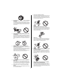
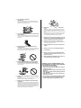
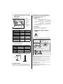
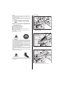
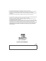
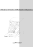
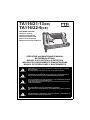
TA116/21-13(CE)
TA116/22-9(CE)
FINE WIRE STAPLER
PNEUMATIC STAPLER
PNEUMATISCHER HEFTER
AGRAFEUSE ONEUMATIQUE
GRAFFATRICE PNEUMATICA
MÁQUINA GRAPADORA NEUMÁTICA
OPERATING and MAINTENANCE MANUAL
BETRIEBSANLEITUNG
MANUEL D’UTILISATION et D’ENTRETIEN
MANUALE DI FUNZIONAMENTO E MANUTENZIONE
MANUAL DE OPERACIONES Y MANTENIMIENTO
BEFORE USING THIS TOOL, STUDY THIS MANUAL TO ENSURE SAFETY WARNING
AND INSTRUCTIONS.
KEEP THESE INSTRUCTIONS WITH THE TOOL FOR FUTURE REFERENCE.
WARNING
LESEN SIE VOR INBETRIEBNAHME DES GERÄTES DIE GEBRAUCHS- UND SICHERHEITSHINWEISE. BITTE BEWAHREN SIE DIE GEBRAUCHS- UND SICHERHEITSHINWEISE AUF, DAMIT SIE AUCH SPÄTER EINGESEHEN WERDEN KÖNNEN.
ACHTUNG
AVERTISSEMENT
ATTENZIONE
ATENCIÓN
AVANT D’UTILISER CET OUTIL, LIRE CE MANUEL ET LES CONSIGNES DE SECURITE
AFIN DE GARANTIR UN FONCTIONNEMENT SUR.
CONSERVER CE MANUEL EN LIEU SUR AVEC L’OUTIL AFIN DE POUVOIR LE CONSULTER ULTERIEUREMENT.
PRIMA DI USARE QUESTA MACCHINA, STUDIARE IL MANUALE PER PRENDERE ATTO
DEGLI AVVERTIMENTI E DELLE ISTRUZIONIPER LA SICUREZZA.
TENERE QUESTE ISTRUZIONI INSIEME ALLO STRUMENTO PER CONSULTAZIONI FUTURE.
PARA EVITAR GRAVES DAÑOS PERSONALES O EN LA PROPIEDAD.
ANTES DE EMPLEAR LA HERRAMIENTA, LEER CON ATENCIÓN Y COMPRENDER LOS
SIGUIENTES INSTRUCCIONES DE SEGURIDAD.
ENGLISH
OPERATING and MAINTENANCE MANUAL
INDEX
1. SAFETY INSTRUCTIONS ..................................................3
2. SPECIFICATIONS AND TECHNICAL DATA .................... 6
3. AIR SUPPLY AND CONNECTIONS .................................. 6
4. INSTRUCTIONS FOR OPERATION .................................. 7
5. MAINTENANCE.................................................................. 9
6. STORAGE ..........................................................................9
7. TROUBLE SHOOTING/REPAIRS......................................9
WARNING
BEFORE USING THIS TOOL, STUDY THIS MANUAL TO ENSURE SAFETY WARNING AND INSTRUCTIONS.
KEEP THESE INSTRUCTIONS WITH THE TOOL FOR FUTURE REFERENCE.
1. SAFETY INSTRUCTIONS
PRECAUTIONS ON USING THE TOOL
1.
WARNING
TO AVOID SEVERE PERSONAL INJURY OR PROPERTY
DAMAGE
BEFORE USING THE TOOL, READ CAREFULLY AND UNDERSTAND THE FOLLOWING "SAFETY INSTRUCTIONS". FAILURE TO FOLLOW WARNINGS COULD
RESULT IN DEATH OR SERIOUS INJURY.
3
WEAR SAFETY GLASSES OR GOGGLES
Danger to the eyes always exists due to the possibility of
dust being blown up by the exhausted air or of a fastener flying up due to the improper handling of the tool. For these
reasons, safety glasses or goggles shall always be worn
when operating the tool.
The employer and/or user must ensure that proper eye protection is worn. Eye protection equipment must conform to
the requirements of Council Directive 89/686/EEC of 21
DEC. 1989 (the American National Standards Institute,
ANSI Z87.1) and provide both frontal and side protection.
The employer is responsible to enforce the use of eye protection equipment by the tool operator and all other personnel in the work area.
NOTE: Non-side shielded spectacles and face shields
alone do not provide adequate protection.
2.
3.
4.
6.
DO NOT USE A WRONG FITTINGS
The connector on the tool must not hold pressure when air
supply is disconnected. If a wrong fitting is used, the tool
can remain charged with air after disconnecting and thus
will be able to drive a fastener even after the air line is disconnected, possibly causing injury.
8.
DISCONNECT THE AIR SUPPLY AND EMPTY THE
MAGAZINE WHEN THE TOOL IS NOT IN USE
Always disconnect the air supply from the tool and empty
the magazine when operation has been completed or suspended, when unattended, moving to a different work area,
adjusting, disassembling, or repairing the tool, and when
clearing a jammed fastener.
9.
INSPECT SCREW TIGHTNESS
Loose or improperly installed screws or bolts cause accidents and tool damage when the tool is put into operation.
Inspect to confirm that all screws and bolts are tight and
properly installed prior to operating the tool.
EAR PROTECTION MAY BE REQUIRED IN SOME ENVIRONMENTS
As the working condition may include exposure to high
noise levels which can lead to hearing damage, the employer and user should ensure that any necessary hearing protection is provided and used by the operator and others in
the work area.
DO NOT USE ANY POWER SOURCE EXCEPT AN AIR
COMPRESSOR
The tool is designed to operate on compressed air. Do not
operate the tool on any other highpressure gas, combustible gases (e.g., oxygen, acetylene, etc.) since there is the
danger of an explosion. For this reason, absolutely do not
use anything other than an air compressor to operate the
tool.
OPERATE WITHIN THE PROPER AIR PRESSURE
RANGE
The tool is designed to operate within an air pressure range
of 5 to 6.9 bar (70 to 100 p.s.i.).
The pressure should be adjusted to the type of the work being fastened. The tool shall never be operated when the operating pressure exceeds 6.9 bar (100 p.s.i.).
Never connect the tool to air pressure which potentially exceeds 13.8 bar (200 p.s.i.) as the tool can burst.
Thinner
5.
7.
10. DO NOT TOUCH THE TRIGGER UNLESS YOU INTEND
TO DRIVE A FASTENER
Whenever the air supply is connected to the tool, never
touch the trigger unless you intend to drive a fastener into
the work. It is dangerous to walk around carrying the tool
with the trigger pulled, and this and similar actions should
be avoided.
Gasoline
DO NOT OPERATE THE TOOL NEAR A FLAMMABLE
SUBSTANCE
Never operate the tool near a flammable substance (e.g.,
thinner, gasoline, etc.). Volatile fumes from these substances could be drawn into the compressor and compressed together with the air and this could result in an explosion.
11. NEVER POINT THE DISCHARGE OUTLET TOWARD
YOURSELF AND OTHER PERSONNEL
If the discharge outlet is pointed toward people, serious accidents may be caused when misfiring. Be sure the discharge outlet is not pointed toward people when connecting
and disconnecting the hose, loading and unloading the fasteners or similar operations.
NEVER USE THE TOOL IN AN EXPLOSIVE ATMOSPHERE
Sparks from the tool may ignite atmospheric gases, dust or
other combustible materials.
4
12. USE SPECIFIED FASTENERS
(SEE PAGE 6)
The use of fasteners other than specified fasteners will
cause the tool malfunction. Be sure to use only specified
fasteners when operating the tool.
18. WHEN USING THE TOOL OUTSIDE OR ELEVATED
PLACE
When fastening roofs or similar slanted surface, start fastening at the lower part and gradually work your way up.
Fastening backward is dangerous as you may lose your foot
place.
Secure the hose at a point close to the area you are going
to drive fasteners. Accidents may be caused due to the
hose being pulled inadvertently or getting caught.
13. PLACE THE DISCHARGE OUTLET ON THE WORK SURFACE PROPERLY
Failure to place the discharge outlet of the nose in a proper
manner can result in a fastener flying up and is extremely
dangerous.
19. NEVER USE THE TOOL IF ANY PORTION OF THE TOOL
CONTROLS (e.g., TRIGGER) IS INOPERABLE, DISCONNECTED, ALTERED OR NOT WOKING PROPERLY
20. NEVER ACTUATE THE TOOL INTO FREE SPACE
This will avoid any hazard caused by free flying fasteners
and excessive strain of the tool.
21. ALWAYS ASSUME THAT THE TOOL CONTAINS FASTENERS
14. KEEP HANDS AND BODY AWAY FROM THE DISCHARGE OUTLET
When loading and using the tool, never place a hand or any
part of body in fastener discharge area of the tool. It is very
dangerous to hit the hands or body by mistake.
22. RESPECT THE TOOL AS A WORKING IMPLEMENT
23. NO HORSEPLAY
24. NEVER LOAD THE TOOL WITH FASTENERS WHEN
ANY ONE OF THE OPERATING CONTROLS (e.g., TRIGGER) IS ACTIVATED
25. WHEN DISPOSING THE MACHINE OR ITS PARTS, FOLLOW THE RELEVANT NATIONAL RULES
15. DO NOT DRIVE FASTENERS CLOSE TO THE EDGE
AND CORNER OF THE WORK AND THIN MATERIAL
The workpiece is likely to split and the fastener could fly free
and hit someone.
OBSERVE THE FOLLOWING GENERAL CAUTION IN ADDITION TO THE OTHER WARNINGS
CONTAINED IN THIS MANUAL
• Do not use the tool as a hammer.
• Always carry the tool by the grip, never carry the
tool by the air hose.
• The tool must be used only for the purpose it was
designed.
• Never remove, tamper with the operating controls
(e.g., TRIGGER)
• Keep the tool in a dry place out of reach of children when not in use.
• Do not use the tool without Safety Warning label.
• Do not modify the tool from original design or
function without approval by MAX CO., LTD.
16. DO NOT DRIVE FASTENERS ON TOP OF OTHER FASTENERS
Driving fasteners on the top of other fasteners may cause
deflection fasteners which could cause injury.
17. REMOVING THE FASTENERS AFTER COMPLETING
OPERATION
If fasteners are left in the magazine after the completion of
operation, there is the danger of a serious accident occurring prior to the resumption of operation, should the tool be
handled carelessly, or when connecting the air fitting. For
this reason, always remove all fasteners remaining in the
magazine after completion of the operation.
5
2. SPECIFICATIONS AND TECHNICAL DATA
1.
5 to 6.9 bar (70 to 100 p.s.i.). Select the operating air pressure
within this range for best fastener performance.
DO NOT EXCEED 6.9 bar (100 p.s.i.).
4.
TECHNICAL DATA
NOISE
A-weighted single-event sound power level
TA116/22-9 (CE) ------ LWA, 1S, d 84.9 dB
TA116/21-13 (CE) ------ LWA, 1S, d 86.5 dB
A-weighted single-event emission sound pressure level at
work station
TA116/22-9 (CE) ------ LpA, 1S, d 78.9 dB
TA116/21-13 (CE) ------ LpA, 1S, d 80.0 dB
These values are determined and documented in accordance to EN12549 : 1999.
NAME OF PARTS
2
1 Frame
2 Cylinder Cap
3 Air Exhaust
Port
4 Slider Unit
5 Magazine
6 Trigger
7 Grip
8 Click Lever
9 Warning Label
(back side)
0 Outlet
7
1
3
8
4
5
6
9
0
2.
RECOMMENDED OPERATING PRESSURE:
5.
APPLICATIONS
∗ Interior decoration
∗ Fastening Plywoods (for interior or furnitures)
∗ Upholstering chair, sofa, and other furnitures
TOOL SPECIFICATIONS
PRODUCT NO.
TA116/22-9(CE)
TA116/21-13(CE)
HEIGHT
152mm (6'')
152mm (6'')
WIDTH
48mm (2'')
48mm (2'')
LENGTH
237mm (8'')
237mm (8'')
WEIGHT
1kg (2.2Ibs)
1kg (2.2Ibs)
RECOMMENDED
5 to 6.9bar
OPERATING PRESSURE (70 to 100p.s.i)
5 to 6.9bar
(70 to 100p.s.i)
LOADING CAPACITY
180 Staples
150 Staples
AIR CONSUMPTION
0.31 l (0.011ft3) at 0.34 l (0.012ft3) at
6.9 bar (100p.s.i.) 6.9 bar (100p.s.i.)
operating pressure operating pressure
3. AIR SUPPLY AND CONNECTIONS
WARNING
Read section titled "SAFETY INSTRUCTIONS".
[AIR SUPPLY & CONNECTIONS]
Air compressor
∗ The machine has been compactly designed in order to improve operating weight balance.
3.
Regulator
Oiler
Air filter
Air hose
FASTENER SPECIFICATIONS
PRODUCT NO. TA116/22-9(CE)
TA116/21-13(CE)
CROWN
9.3mm (3/8'')
13mm (1/2'')
LENGTH
6 to 16mm (1/4'' to 5/8'') 6 to 16mm (1/4'' to 5/8'')
WIDTH
0.77mm (0.030'')
0.91mm (0.036'')
THICKNESS
0.55mm (0.0215'')
0.70mm (0.0275'')
GAUGE
22
21
3-piece airset
Used at 5 to 6.9 bar (70 to 100 p.s.i.)
CROWN
FITTINGS: Install a male plug on the tool which is free flowing
and which will release air pressure from the tool when disconnected from the supply source.
LENGTH
THICKNESS
HOSES: Hose has a min. ID of 6 mm (1/4") and max. length of
no more than 5 meters (17").
The supply hose should contain a fitting that will provide "quick
disconnecting" from the male plug on the tool.
WIDTH
TOOL AIR FITTINGS:
SUPPLY SOURCE: Use only clean regulated compressed air as
a power source for the tool.
This tool uses a 1/4" N.P.T. male plug. The inside diameter
should be 7mm (.28") or larger. The fitting must be capable of discharging tool air pressure when disconnected from the air supply.
3-PIECE AIRSET (Air filter, Regulator, Oiler):
Refer to TOOL SPECIFICATIONS for setting the correct operating pressure for the tool.
6
NOTE:
A filter will help to get the best performance and minimum wear
from the tool because dirt and water in the air supply are major
causes of wear in the tool.
Frequent, but not excessive, lubrication is required for the best
performance. Oil added thru the air line connection will lubricate
the internal parts.
STAPLE LOADING
Slider Unit
2
Click Lever
4. INSTRUCTIONS FOR OPERATION
1
Read section titled "SAFETY INSTRUCTIONS".
1.
BEFORE OPERATION
Check the following prior operation.
1 Wear Safety Glasses or Goggles.
2 Do not connect the air supply.
3 Inspect screw tightness.
4 Check operation of the trigger if moving smoothly.
5 Connect the air supply.
6 Check the air-leakage. (The Tool must not have the airleakage.)
7 Disconnect the air supply.
1
2
Remove the click lever.
Pull out the slider unit.
A set of staples
(Insert it with the square
feet of staples up)
WARNING
Magazine
2.
OPERATION
Wear safety glasses or goggles. Danger to the eyes always exists due to the possibility of dust being blown up by the exhausted
air or of a fastener flying up due to the improper handling of the
tool. For these reasons, safety glasses or goggles shall always
be worn when operating the tool.
The employer and/or user must ensure that proper eye protection
is worn. Eye protection equipment must conform to the requirements of Council Directive 89/686/EEC of 21 DEC. 1989 (the
American National Standards Institute, ANSI Z87.1) and provide
both frontal and side protection.
The employer is responsible to enforce the use of eye protection
equipment by the tool operator and all other personnel in the work
area.
NOTE: Non-side shielded spectacles and face shields alone do
not provide adequate protection.
3
Insert a set of staples into the magazine with the square feet
of staples up.
Slider Unit
Click Lever
WARNING
Keep hands and body away from the discharge outlet when driving the fasteners because of dangerous of hitting the hands or
body by mistake.
4
7
Press the slider unit to set the click lever securely.
TEST OPERATION
1 Adjust the air pressure at 5 bar (70 p.s.i.) and connect the
air supply.
2 Without touching the trigger, depress the staple discharge
outlet against the work-piece.
Pull the trigger. (The tool must fire the fastener.)
3 Adjust the air pressure as much as the lowest possible according the length of fastener and the hardness of workpiece.
CLEARING JAMMED STAPLES
Slider Unit
Flat-blade
screwdriver
Driver
Guide
Cover
AIR HOSE CONNECTION
Connect the air chuck to the air plug.
WARNING
When connecting the air chuck, do not point the staple discharge outlet at any part of your body or at another preson,
and do not touch the trigger.
1
2
3
DRIVING FASTENERS
4
5
2
1
WARNING
Trigger
ALWAYS disconnect air supply before clearing jammed fastener.
Outlet
1
2
Disconnect the air hose.
Remove the set of staples from the magazine.
Take out the 4 hexagon socket head cap screws from the
magazine and remove the driver guide cover.
Clear the staples jammed inside the nose using a thin iron
bar or a flat-blade screwdriver.
Reinstall the driver guide cover, reinsert the set of staples
and bring back the slider unit.
Depress the staple discharge outlet against a place where
you want to drive a staple.
Pull the trigger.
8
5. MAINTENANCE
6. STORAGE
1
1
ABOUT PRODUCTION YEAR
This product bears production number at the lower part of
the grip of the main body. The two digits of the number from
left indicates the production year.
2
3
(Example)
08826035D
4
When not in use for an extended period, apply a thin coat of
the lubricant to the steel parts to avoid rust.
Do not store the tool in a cold weather environment. Keep
the tool in a warm area.
When not in use, the tool should be stored in a warm and
dry place. Keep out of reach of children.
All quality tools will eventually require servicing or replacement of parts because of wear from the normal use.
Year 2008
2
3
4
5
DO NOT FIRE THE STAPLER WHEN IT IS EMPTY
USE A 3-PIECE AIRSET
Failure to use a 3-piece airset allows the moisture and dirt
inside compressor to pass into the tool directly. This causes
rust and wear, and results in a poor operating performance.
The hose length between airset and tool should be no longer than 5 m since a longer length results in a reduction in air
pressure.
USE RECOMMENDED OIL
The velocite or turbine oil should be used to lubricate the
tool. Upon completion of operations, place 2 or 3 drops of
oil into the air plug inlet with the jet oiler. (Recommended Oil
: ISO VG32)
INSPECT AND MAINTAIN DAILY OR BEFORE OPERATION
7. TROUBLE SHOOTING/REPAIRS
The troubleshooting and/or repairs shall be carried out only by
the MAX CO., LTD. authorised distributors or by other specialists.
WARNING
Disconnect air supply and empty the magazine when inspecting or maintaining the tool.
(1)
(2)
(3)
(4)
Drain air line filter and compressor
Keep lubricator filled in air 3-pieces set
Clean filter element of air 3-pieces set
Tighten all screws
9
•
•
•
•
The content of this manual might be changed without notice for improvement.
Anderungen der Betriebsanleitung zum Zwecke der Verbesserung ohne Ankundigung vorbehalten.
Le contenu de ce manuel est sujet a modification sans preavis a des fins d'amelioration.
I contenuti di questo manuale possono essere cambiati senza preavviso per motivi di miglioramento
del prodotto.
• El contenido de este manual puede ser cambiado sin noticia previa para mejoramiento.
• The specifications and design of the products in this manual will be subject to change without advance
notice due to our continuous efforts to improve the quality of our products.
• Änderungen bei technischen Daten und Design der Produkte in diesem Handbuch im Sinne der
Produktverbesserung bleiben vorbehalten.
• Les caractéristiques et la conception des produits mentionnés dans ce manuel sont sujettes à des
modifications sans préavis en raison de nos efforts continus pour améliorer la qualité de nos produits.
• Le caratteristiche e la concezione dei prodotti menzionati in questo manuale sono soggette a
modifiche senza preavviso a causa dei nostri sforzi continui per migliorare la qualità dei nostri prodotti.
• Las características y la concepción de los productos mencionados en este manual están sujetas a
modificaciones sin preaviso debido a nuestros esfuerzos continuos para mejorar la calidad de
nuestros productos.
Camerastraat 19
1322 BB Almere The Netherlands
Phone: +31-36-546-9669
FAX: +31-36-536-3985
www.max-ltd.co.jp/int/ (GLOBAL Site)
www.max-europe.com (EUROPE Site)
4008586
100414-00/03