1
YARDMACHINES
OPERATOR'S
MANUAL
LOG SPLITTER
VERTICAL
SHAFT
IMPORTANT:
READ SAFETY RULES AND INSTRUCTIONS
CAREFULLY
Warning:
This unit is equipped with an internal combustion engine and should not be used on or near any unimproved forestcovered, brush-covered or grass-covered land unless the engine's exhaust system is equipped with a spark arrester meeting
applicable local or state laws (if any). If a spark arrester is used, it should be maintained in effective working order by the operator.
In the State of California the above is required by law (Section 4442 of the California Public Resources Code). Other states may have
similar laws. Federal laws apply on federal lands. A spark arrester for the muffler is available through your nearest engine authorized
service dealer or contact the service department, P.O. Box 368022 Cleveland, Ohio 44136-9722.
MTD PRODUCTS
PRINTED IN U.S.A.
INC. P.O. BOX 368022 CLEVELAND,
OHIO 44136-9722
FORM NO. 770-10055A
(5/99)
SECTION
1: FINDING YOUR MODEL NUMBER
This Operator's Manual is an important part of your new log splitter. It will help you assemble, prepare and
maintain your log splitter. Please read and understand what it says.
Before you start to prepare your log splitter for its first use, please locate the model plate and copy the
information from it in this Operator's Manual. The information on the model plate is very important if you need
help from your dealer or the MTD customer support department.
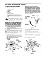
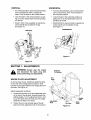
• Every log splitter has a model plate. You can locate it by standing behind the unit in the operating
position and looking down at the hydraulic tank. See Figure 1.
This is where your model number will be.
I
XXX-X-XXX-X-XXX
XXXXXXXXXXX
This is where your serial number will be.
Copy the model number here:
CLEVELAND,
OHIO
44136 •
Copy the serial number here:
Figure 1
SECTION
2: CALLING
CUSTOMER
SUPPORT
• LOCATE YOUR MODEL NUMBER AND SERIAL NUMBER m Record this information in the space
provided. To find your unit's specific model number and serial number, see SECTION 1: FINDING
YOUR MODEL NUMBER.
• If you are having difficulty assembling this product or if you have any questions regarding the controls,
operation or maintenance of this unit, please call the Customer Support Department.
• Customer Support can be reached by dialing: 1- (330) 220-4MTD
(4683)
or
1- (800)-800-7310
• Please have your model number and serial number ready when you call.
• Although both numbers are important, you will be asked to enter only your serial number before your
call can be processed.
SECTION
3: IMPORTANT
RULES FOR SAFE OPERATION
WARNING:
THIS SYMBOL POINTS OUT IMPORTANT SAFETY INSTRUCTIONS WHICH, IF
NOT FOLLOWED, COULD ENDANGER THE PERSONAL SAFETY AND/OR PROPERTY OF
YOURSELF AND OTHERS. READ AND FOLLOW ALL INSTRUCTIONS
IN THIS MANUAL
BEFORE ATTEMPTING TO OPERATE YOUR LOG SPLITTER. FAILURE TO COMPLY WITH
THESE INSTRUCTIONS MAY RESULT IN PERSONAL INJURY. WHEN YOU SEE THIS SYMBOL
HEED ITS WARNING.
WARNING:
the State of California
DANGER:
The Engine Exhaust from this product contains chemicals
to cause cancer, birth defects or other reproductive
harm.
known
to
Your log splitter was built to be operated according to the rules for safe operation in
this manual. As with any type of power equipment, carelessness or error on the part of the operator
can result in serious injury. If you violate any of these rules, you may cause serious injury to yourself
or others.
2
1. TRAINING
•
the splitter on level ground also prevents the spillage of gasoline from the fuel tank.
Before operating this splitter, read and understand
this operator's manual completely. Become familiar with it for your own safety. To fail to do so may
cause serious injury. Do not allow anyone to operate your splitter who has not read this manual.
Keep this manual in a safe place for future and regular reference and for ordering replacement parts.
•
Never use your splitter for any other
splitting wood. It is designed for this
other use may cause an injury. Your
precision piece of power equipment,
Therefore, exercise extreme caution
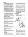
Never attempt to move the log splitter over hilly or
uneven terrain without a tow vehicle or adequate
help.
Always block the wheels to prevent movement of
log splitter while in operation.
purpose than
use and any
log splitter is a
not a toy.
at all times.
Check the fuel before starting the engine. Gasoline
is an extremely flammable fuel. Do not fill the gasoline tank indoors, when the engine is running, or
while the engine is still hot. Replace gasoline cap
securely and wipe off any spilled gasoline before
starting the engine as it may cause a fire or explosion.
• Never allow children to operate your log splitter. Do
not allow adults to operate it without proper instruction. Only persons well acquainted with these rules
of safe operation should be allowed to use your log
splitter.
•
• Only the operator is to be near your log splitter during use. Keep all others, including pets and children, a minimum of 20 feet away from your work
zone. Flying wood can be hazardous. If a helper is
assisting in loading logs, never activate the control
until the helper is clear of the area. More accidents
occur when more than one person operates the log
splitter than at any other time.
•
Both ends of each log must be cut as square as
possible to help prevent the log from riding out of
the splitter during operation.
3. OPERATION
Vertical Operating Position: Stand in front of the
log splitter.
Horizontal Operating Position: Stand behind the
reservoir tank. See illustrations.
No one should operate this unit while intoxicated or
while taking medication that impairs the senses or
reactions. A clear mind is essential for safety.
Never allow a person who is tired or otherwise not
alert to use your splitter.
PREPARATION
=
•
Never wear loose clothing or jewelry that can be
caught by moving parts of your log splitter and pull
you into it. Keep clothing away from all moving
parts of your log splitter.
• Wear proper head gear to keep hair away from
moving parts. Always wear protective hearing
devices as needed.
• Always wear safety shoes. A dropped log can seriously injure your foot.
• Always wear safety glasses or goggles while operating your splitter. A piece of splitting log could fly
off and hit your eyes.
• Wear leather work gloves. Be sure they are tight fitting without loose cuffs or draw strings.
•
Use your log splitter in daylight, or under good artificial light.
•
Never operate your splitter on slippery, wet, muddy
or icy surfaces. Safe footing is essential in preventing accidents.
•
Never operate your splitter while it's still attached to
a towing vehicle.
•
Only operate your splitter on level ground and not
on the side of a hill. It could tip, or rolling logs or
poor footing could cause an accident. Operating
Know how to stop the unit and disengage the controls.
• Never place hands or feet between log and splitting wedge or between log and end plate during forward or reverse stroke. To do so may result in
crushed or amputated fingers or toes, or worse,
you may lose an arm or foot.
3
•
Do not straddle the splitter when using it. A slip in
any position could result in a serious injury.
•
Do not step over your log splitter when the engine
is running. You may trip or accidentally activate the
splitting wedge if you step over. If you need to get
to the other side, walk around.
•
protective features removed. These safety devices
are for your protection.
Never try to split two logs on top of each other. One
may fly out and injure you.
• When loading the log splitter, place your hands on
the side of the log, not at the ends. Never attempt
to load your splitter while the splitting wedge is in
motion. You may get caught by the wedge and
injured.
• Only use your hand to operate the splitting wedge
or control lever. Never use your foot or a rope or
any other extension device. This could result in
your inability to stop your splitter quickly enough to
avoid injury.
•
•
•
Replace all damaged or worn parts such as
hydraulic hoses and fittings immediately with manufacturer approved replacement parts.
•
Do not change the engine governor settings or
overspeed the engine. This increases the hazard of
personal injury. The maximum engine speed is preset by the manufacturer and is within safety limits.
•
Do not alter your splitter in any manner such as
attaching a rope or extension to the control lever or
adding to the width or height of the wedge. Such
alterations may cause your splitter to be unsafe.
• Perform all recommended maintenance
dures before you use your splitter.
Always keep fingers away from any cracks that
open in the log during splitting operation. They can
quickly close and pinch or amputate your fingers.
proce-
• Do not service or repair your log splitter without disconnecting the spark plug wire and moving it away
from the spark plug.
Never attempt to split woods across the grain.
Some types of wood may burst or fly out of your
splitter and result in injury to you or a bystander.
• Never store the equipment with gasoline in the tank
inside of a building where ignition sources are
present, such as hot water and space heaters,
clothes dryers and the like. Allow the engine to cool
before storing in any enclosure.
•
For logs that are not cut square, the longest portion of the log should be rotated down and the most
square end placed against the splitting wedge.
•
Keep your work area clean. Immediately remove
split wood around your splitter so that you do not
stumble over it. Clean chips and dirt off end plate
(wood platform) after each log is split, or whenever
necessary to maintain flat contact between wood
and end plate (platform).
•
•
Never move the log splitter while the engine is running.
•
Never leave your log splitter unattended with the
engine running. Shut off the engine if you are leaving your splitter, even for a short period of time.
Someone could accidentally activate the splitting
wedge and be injured.
• The hydraulic system of your log splitter requires
careful inspection, along with the mechanical parts.
Be sure to replace frayed, kinked, or otherwise
damaged hydraulic components.
•
Do not run engine in an enclosed area. Exhaust
gases contain carbon monoxide. This odorless gas
can be deadly when inhaled.
•
Be careful not to touch the muffler after the engine
has been running. It will be HOT!
•
If the equipment should start to vibrate abnormally,
stop the engine and check immediately for the
cause. Vibration is generally a warning of trouble.
•
When cleaning, repairing
tain all moving parts have
spark plug wire and keep
plug to prevent accidental
4. CUSTOMER
Always store gasoline in an approved, tightly
sealed container. Store the container in a cool, dry
place. Do not store in a building where ignition
sources are present.
• To reduce fire hazard, keep engine free of grass,
leaves, wood chips, and excessive grease and oil.
•
Fluid escaping from a very small hole can be
almost invisible. Do not check for leaks with your
hand. Escaping fluid under pressure can have sufficient force to penetrate skin, causing serious personal injury. Leaks can be located by passing a
piece of cardboard or wood over the suspected
leak and looking for discoloration.
• Should it become necessary to loosen or remove
any hydraulic fitting or line, be sure to relieve all
pressure by shutting off the engine and moving the
control handle back and forth several times.
• Do not remove the cap from the hydraulic tank or
reservoir while your log splitter is running. Hot oil
under pressure could cause injury.
or inspecting, make cerstopped. Disconnect the
the wire away from the
starting.
•
RESPONSIBILITIES
Do not operate your splitter in poor mechanical
condition or when in need of repair.
The pressure relief valve on your splitter is preset
at the factory. Do not adjust the valve. Only a qualified service technician should perform this adjustment.
Completely drain fuel tank prior to storage. This
guards against accumulation of fuel fumes which
could result in a fire hazard.
Periodically check that all nuts, bolts, screws, hose
clamps and hydraulic fittings are tight to be sure
equipment is in safe working condition. Where
appropriate, check all safety guards and shields to
be sure they are in the proper position. Never operate your splitter with safety guards, shields or other
Never store log splitter outside without a waterproof cover. Rain will cause rust on the inside of
the cylinder.
4
5. TOWING
• The coupler must be secured to the log splitter
tongue tube with the original equipment bolts and
nuts. See your local dealer for replacement parts.
Coupler nuts should be tightened securely (23 foot
pounds).
This unit should not be towed on any street, highway or public road without checking the existing
federal, local or state vehicle requirements. Any
licensing or modifications such as taillights, etc.,
needed to comply with the existing federal, local or
state vehicle requirements is the sole responsibility
of the purchaser.
*If a "Statement of Origin" is required in your state,
see your local dealer to receive one.
•
Before towing, be certain the log splitter is correctly and securely attached to the towing vehicle,
and the safety chains are in place. Leave slack in
chains for turning allowance.
• Use a class I or higher hitch ball with a 1-7/8" ball.
Keep ball socket and clamp face lubricated with
chassis grease.
Do NOT tow the log splitter faster than 45 MPH.
Higher speeds may damage the log splitter. Excessive speeds may cause the log splitter to "fishtail"
or otherwise become unstable.
•
Check the tire pressure on log splitter tires. 30 PSI
is the maximum for highway travel.
Do not allow anyone to sit or ride on your splitter.
They can easily fall off and be seriously injured.
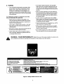
read, understand and follow the warnings and instructions in this manual and on the machine.
WARNING - YOUR RESPONSIBILITY:
Restrict the use of this power machine to persons who
,_
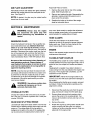
MOVING
LOG SPLITTER
BY HAND:
Lock beam in horizontal position.
Attach coupler to Class I or higher hitch with 1-7/8" ball. Latch securely.
Raise jack stand and latch securely in full up position.
Attach safety chains to tow vehicle.
I TOWING
SPLITTER:
Do not towLOG
faster
than 45 mph. High speed may cause loss of control.
Check local Tstate and federal requirements before towin,_ on any public road.
Lock beam in horizontal position.
Lock jack stand in down position.
Do not attempt to move log splitter
up or down a slope by hand
i $30230
I
_
I VERTICAL
II IIII
_ill
OPERATOR'S INSTRUCTIONS
1.m_l_ _,_r onr=l_d g.,_.
_
2.L0_o_H_DnUtorV0_ap_on.
3. S_thee_lne I[l_lZieat ms,humspeed.
L
•
•
• Check vehicle hitch, ball and coupler for signs of
wear or damage. Replace any parts that are worn
or damaged before towing.
I
Make sure beam assembly is securely latched in
the horizontal position and jack stand (if provided)
is pivoted and secured in the UP position before
towing the log splitter. Never tow with the beam in
the vertical position.
• When parking, storing or operating your log splitter, keep the coupler off the ground so dirt will not
build up in the ball socket.
• Be sure the coupler is secured to the hitch ball and
the lock lever is down tight and locked.
I
•
,_l:#f---
_
-j
1'
HI
b_,q_0_spmngwo_.
READ
OPERATOR
S MANUAL
_:._.,
_, "__,,,U_iid
_"._
•
.
•
_--_l_,_,_,
9. Movear_e
r'eebot
ha_e °PPOSPO
_ spl_ngdize_l°_t° '_'_z'd_ew4ge.
HORIZONTAL
Figure 2 Safety labels found on unit
5
SECTION
ITEMS
4: UNPACKING
REQUIRED
AND ASSEMBLY
FOR ASSEMBLY
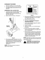
5.
Place the end of the tongue assembly in
between the brackets on the wheel and reservoir tank assembly. Secure with hardware just
removed and tighten to 23 ft-lbs. See Figure 3.
6.
Remove the spring clip and clevis pin from the
jack stand. Pivot the jack stand to the operating
position (90°), and secure with spring pin and
clevis pin. See Figure 4.
• Crowbar or Large Screwdriver
• Adjustable Wrenches
• Screwdriver
• Cutters
• Engine Oil
• Unleaded Gasoline
• Dexron III Automatic Transmission Fluid or
10W AW hydraulic fluid (approximately 7 gallons)
WARNING:
Exercise extreme
Clevis Pin
Tongue
Assembly
Cli
Spring
caution
as parts are very heavy. Mechanical
handling equipment should be used, or
sufficient people to prevent injury.
IMPORTANT:
This unit is shipped WITHOUT
GASOLINE or OIL in the engine. After assembly, see separate engine operator's manual for
proper fuel and engine oil recommendations.
1.
Pry the top, sides and ends off crate using a
crowbar or large screwdriver.
2.
Set panels aside to avoid tire punctures or personal injury.
3.
Jack Stand
Figure 4
.
Remove and discard plastic bag that covers unit.
8.
Remove the lag screw and washer which
secures the beam assembly to the bottom of the
crate.
9.
Lower the beam assembly to its horizontal position. Make certain the beam is locked securely
with the horizontal beam lock. See Figure 5.
Note: Do Not remove the banding from around the
tank until the log splitter is assembled.
4.
Remove the two bolts, lock washers and hex
nuts that secure the tongue assembly to the
beam assembly. Unlock the two beam locks by
pulling out on the beam locks and pivoting them
down. Remove the tongue assembly.
See Figure 3.
Bracket
Cut the two straps from around the reservoir
tank assembly.
10. Pull the log splitter off the pallet.
Tongue
Assembly
Horizontal
Vertical
Hex
Bolts
Hex
Nuts
Horizontal
Beam Lock
Lock
Washers
Figure 3
Figure 5
6
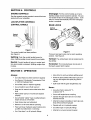
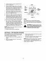
PREPARING
.
2.
THE ENGINE
Place the log splitter on a firm, level surface.
+
Fill engine with gasoline and oil as instructed in
the separate engine manual packed with your
log splitter.
3"to3 /2"
PREPARING
+
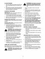
Maintain fluid
level within 3"
to 3 1/2" from
top at all times.
Do not overfill.
THE LOG SPLITTER
Lubricate the beam area where splitting wedge
will slide with engine oil (DO NOT USE
GREASE). Make certain to oil both front and
back of the beam face.
.
2.
Check fluid level using scale. Never run
below this level. Pump will be ruined.
i20739
Figure 7
Remove reservoir vent plug. See Figure 6.
Reservoir
Vent Plu
4.
Disconnect the spark plug wire. Prime the pump
by pulling the recoil starter, to turn the engine
over, approximately 10 times.
5.
Reconnect the spark plug wire.
6.
Start engine. (See Starting The Engine in
OPERATION SECTION)
7.
Use the control handle to engage the wedge to
the far extended position.
8.
Retract the wedge.
9.
Refill tank to within 3" to 3 1/2" from the top of
the fill tube.
10. Extend and retract the wedge 12 complete
cycles to remove trapped air in the system (system is "self-bleeding").
11. Refill the reservoir to within 3" to 3 1/2" from the
top of the fill tube. Much of the original fluid has
been drawn into the cylinder and hoses. Make
certain to refill the reservoir, to prevent extreme
damage to the hydraulic pump. Failure to refill
the tank will void your warranty.
NOTE: Some fluid may overflow from the vent plug
Figure 6
.
as the system builds heat and the fluid expands and
seeks a balanced level.
Fill the reservoir tank to the within 3" to 3 1/2"
from the top of fill tube with Dexron III automatic
transmission fluid, or 10W AW hydraulic fluid.
Check fluid level using a scale. Do not overfill.
Replace vent plug securely.
See Figure 7.
_
NOTE: The reservoir tank has a capacity of
approximately 4 gallons.
7
splitter
withoutDothe
amount
WARNING:
notproper
operate
the logof
hydraulic oil in the reservoir tank.
SECTION
ENGINE
5: CONTROLS
CONTROLS
See the separate engine operator's manual that was
packed with your log splitter.
LOG SPLITTER
CONTROL
CONTROLS
HANDLE
Disengage:
Pull the control handle up or back.
Splitting wedge moves toward the cylinder. The control handle will lock in the disengage position. It will
return to neutral automatically when the disengage
stroke is complete.
BEAM LOCKS
Vertical
Beam
Handle
Control=
_
Beam Lock
Figure 8
The control handle has three positions.
See Figure 8.
Splitting:
Push the control handle forward or
down. Splitting wedge moves toward the end plate.
Figure 9
There are two beam locks one for each operating
position. See Figure 9.
Vertical: The vertical beam lock is located next to
the oil filter.
Neutral:
Control handle will return to neutral position when handle is released. Splitting wedge stops
in place.
SECTION
Horizontal: The horizontal beam lock is part of
the beam support latch bracket.
6: OPERATION
Always:
• Use clean fluid and check fluid level regularly
• Use Dexron III Automatic Transmission Fluid
or 10W AW hydraulic fluid.
• Use a filter (clean or replace regularly)
• Use a breather cap on fluid reservoir
Allow time for warm-up before splitting wood
Prime the pump before initial start-up by turning over the engine with spark plug disconnected
Split wood with the grain (lengthwise) only
Never:
• Keep end of reservoir return tube below fluid
level
• Use when fluid is below 20 ° F,,
or above 150 ° F.
• Make certain pump is mounted and aligned
properly
• Use a solid engine/pump coupling
• Use a flexible "spider" type coupling between
engine and pump driveshafts
• Operate through relief valve for more than
several seconds
• Keep hoses clear and unblocked
• Attempt to adjust unloading or relief valve settings without pressure gauges
• Bleed air out of hoses before operating
• Operate with air in hydraulic system
• Flush and clean hydraulic system before startup after any malfunction or servicing
• Use teflon tape on hydraulic fittings
• Use "pipe dope" on all hydraulic fittings
• Attempt to cut wood across the grain
TO STOP ENGINE
WARNING:
1.
Move the engine shut-off switch to the OFF position or move throttle control to the STOP position.
2.
After engine has stopped, disconnect spark plug
wire from spark plug to prevent accidental starting while equipment is unattended.
STARTING
Wear leather work gloves,
safety shoes and safety glasses when
operating log splitter. Ensure safe footing.
1.
Place the log splitter on level, dry and solid
ground.
2.
Place the beam in either the horizontal or vertical position and lock in place with the appropriate locking rod.
3.
Block the front and back of both wheels.
THE ENGINE
IMPORTANT:
Refer to the separate engine manual for detailed starting instructions.
4.
Set the engine throttle to maximum speed.
1.
Place the engine shut-off switch to ON position
or move throttle control lever to FAST position.
5.
Place the log against the end plate. Only split
wood in the direction of the grain.
2.
Make sure fuel shut-off located under gasoline
tank is open (if so equipped).
6.
When necessary to stabilize the log, place your
hand only on sides of log, NEVER on the end
between the log and splitting wedge.
7.
ONLY ONE ADULT SHOULD STABILIZE THE
LOG AND OPERATE THE CONTROL HANDLE so the operator has full control over stabilizing the log and movement of the splitting wedge.
Engines
with choke
lever:
Place choke lever
in CHOKE position (a warm engine may not require
choking).
Engines
with primer: Prime engine as instructed in separate engine manual.
3.
Grasp starter handle and pull rope out slowly
until engine reaches start of compression cycle
(rope will pull slightly harder at this point). Let
the rope rewind slowly.
OPERATING
CONTROL
POSITIONS
HANDLE
POSITIONS
• Move control handle FORWARD or DOWN to
split wood.
_
4.
engine,
keep away
mufflera and
ARNING:
When from
restarting
warm
other heated surfaces on the engine.
Pull rope with a rapid, continuous, full arm
stroke. Keep a firm grip on the starter handle.
Let the rope rewind slowly. Do not let starter
handle snap back against starter.
5.
Repeat instructions until engine fires. When
engine starts, move choke lever halfway
between CHOKE and RUN.
6.
Gradually move choke lever to RUN position as
engine warms up.
7.
If weather is cold, run wedge up and down beam
6 to 8 times to circulate the hydraulic fluid.
• Release the control handle to stop the wedge
movement.
• Move control handle BACK or UP to return the
wedge.
TRANSPORTING
1.
.
THE LOG SPLITTER
Lower the beam to its horizontal position. Make
certain the beam is locked securely with the horizontal beam lock.
Unhook the spring clip and remove the clevis pin
from the jack stand. Support the tongue, and
pivot the jack stand up against the tongue.
Secure with the clevis pin and spring clip just
removed.
USING THE LOG SPLITTER
3.
Attach the hitch to a towing vehicle, making certain to latch securely.
Never attempt to cut a log in half sideways. Always
split the log lengthwise. Maximum log length is 24".
4.
Attach the safety chains to the towing vehicle.
5.
Plug in the taillights as instructed in the taillight
kit manual included with your log splitter.
,_
always use theWhen
log splitter
the vertiWARNING:
splittingin heavy
logs,
cal position.
VERTICAL
HORIZONTAL
• For vertical operation, pull the horizontal beam
lock out and pivot it down to release the
beam. Pivot the beam to the vertical position.
• For horizontal operation, pull the vertical beam
lock out and pivot it down. Pivot the beam to
the horizontal position.
• Lock the beam in the vertical position, by pulling out on the vertical beam lock and pivoting
it to the left.
° Lock the beam in the horizontal position; by
pulling out on the horizontal beam lock and
pivoting it to the left.
• Stand in front of the log splitter to operate the
control handle and to stabilize the log.
See Figure 10.
• Stand behind the reservoir tank to operate the
control handle and to stabilize the log.
See Figure 11.
HORIZONTAL
VERTICAL
Figure 11
Figure 10
SECTION
7: ADJUSTMENTS
Attached
To Cylinder
and disconnect the spark plug wire
WARNING:
Always stop the engine
before performing any adjustments.
_
WEDGE
Hex
Bolts
PLATE ADJUSTMENT
As normal wear occurs, periodically adjust the bolts
on the side of the wedge plate as follows to eliminate the excess space between the wedge plate and
the beam. See Figure 12.
Adjust wedge plate as follows:
1.
2.
Loosen the jam nuts on the two adjustment bolts
on the side of the gib plate, located beneath the
splitting wedge. Turn the adjustment bolts in until
snug, then back them off slowly until the wedge
assembly will slide on the beam.
..Wedge
Plate
Adju.=
Bolts
Tighten the jam nuts securely against the gib
plate to hold the adjustment bolts in this position.
Gib Plate
Figure 12
10
Back
Plate
GIB PLATE ADJUSTMENT
Adjust Gib Plate as follows:
Periodically remove and replace the "gibs" (spacers)
between the wedge plate and the back plate as follows. See Figure 12.
1.
Remove the center bolt on top of the wedge
plate. Slide the gib plate out.
2.
Remove and replace the gibs. Reassemble the
gib plate, making certain flat washers are in
place under the gib plate.
3.
Readjust the bolts on the side of the wedge
plate as instructed above.
NOTE: If desired, the gibs may be rotated and/or
turned over for even wear.
SECTION
_
8: MAINTENANCE
even wear. Make certain to readjust the adjustment
bolts so wedge moves freely, but no excess space
exists between the wedge plate and beam.
and disconnect the spark plug wire
WARNING:
Always stop the engine
before performing any maintenance or
repairs.
RESERVOIR
HOSE CLAMPS
Check the hose clamps on the suction hose
(attached to side of the pump) for proper tightness
before each use. Check the hose clamps on the
return hose at least once a season.
FLUID
Check the hydraulic fluid level in the log splitter reservoir tank before each use. Maintain fluid level
within 3" to 3 1/2" from top at all times. Change
the hydraulic fluid in the reservoir every 100 hours of
operation. Disconnect the suction hose from the bottom of the reservoir tank, and drain the fluid into a
suitable container. Refill using only Dexron III automatic transmission fluid or 10W AW hydraulic fluid.
ENGINE
Refer to the separate engine manual for all engine
maintenance instructions.
FLEXIBLE
Be aware of the environment when disposing of
used petroleum products. Please dispose of
used hydraulic fluid, engine oil and any by products from the maintenance of you log splitter at
approved recycling centers.
The flexible pump coupler is a nylon "spider" insert,
located between the pump and engine shaft. Over a
period of time, the coupler will harden and deteriorate.
Replacement is needed if you detect vibration or
noise coming from the area between the engine and
the pump. If the coupler fails completely, you will
experience a loss of power.
NOTE: Drain the fluid and flush the reservoir tank
and hoses with kerosene whenever any repair work
is performed on the tank, hydraulic pump or valve.
Contaminants in the fluid will damage the hydraulic
components. (Should be performed by an authorized service dealer.)
WARNING:
PUMP COUPLER
IMPORTANT:
Never hit the engine shaft in any
manner, as a blow will cause permanent damage to
the engine.
When replacing the flexible pump coupler, proceed
as follows. Follow the instructions carefully as the
alignment is critical.
Use extreme caution when
working with kerosene, as it is an
extremely flammable fluid.
1.
Disconnect the spark plug wire from the spark
plug, and secure it away from the spark plug.
Change the hydraulic filter every 50 hours of operation. Use only a 10 micron hydraulic filter. Order part
number 723-0405.
2.
Remove three nuts and lock washers which
secure the pump to the coupling shield. Two
nuts are at the bottom corners and one is in the
top center.
BEAM AND SPLITTING
3.
Remove the pump.
4.
Rotate the engine by pulling starter handle until
engine coupling half set screw is at bottom.
Loosen set screw using allen wrench. Slide coupling half off of engine shaft.
HYDRAULIC
FILTER
WEDGE
Lubricate both sides of the beam (where it comes into
contact with the splitting wedge) before each use with
engine oil. The wedge plate on the log splitter is
designed so the gibs on the side of the wedge plate
can be removed and rotated and/or turned over for
11
5. Loosensetscrewon pumpcouplinghalf,and
removecouplinghalf.
6. Slidenewenginecouplinghalfontotheengine
shaftuntiltheendoftheshaftisflushwiththe
innerportionofthecouplinghalf.(Theremustbe
spacebetweenendoftheenginesupport
bracketandcouplinghalf.)Tightensetscrew.
7. Installpumpcouplinghalfandkeyonpump
shaft.Rotatecouplinghalfuntilsetscrewfaces
down.Donottightensetscrew.
8. Installnylon"spider"ontoenginecouplinghalf.
9. Alignpumpcouplinghalfwithnylon"spider"by
rotatingengineusingstarterhandle.Slidecouplinghalfintoplacewhileguidingthreemountingboltsthroughholesin pumpsupportbracket.
10.Securewithnutsandwashersremovedearlier.
11.Set.010inchto .060inchclearance
between
thenylon"spider"andtheenginecouplinghalf
by slidinga matchbook
coverbetweenthenylon
"spider"andtheenginecouplinghalfandmovingpumpcouplinghalfas needed.Securepump
couplinghalfwithsetscrew.SeeFigure13.
PUMP
Set
Screw_l____
Nylon
I__
LIII
"Spider"--__._.__.
J_o
Insert
Clearance_
ENGINE
Steel
_Coupling
_es
Figure 13
TIRES
See sidewall of tire for recommended pressure.
Maximum tire pressure under any circumstances is
30 p.s.i. Equal tire pressure should be maintained on
all tires.
WARNING:
Excessive pressure (over
30 p.s.i.) when seating beads may cause
tire/rim assembly to burst with force
sufficient to cause serious injury.
NOTE: Make certain proper clearance is obtained
before tightening set screw.
12. Reattach spark plug wire to spark plug.
SECTION
9: OFF-SEASON
STORAGE
3.
If the log splitter will not be used for a period longer
than 30 days, the following steps should be taken to
prepare the log splitter for storage.
1.
Clean the engine and the entire log splitter thoroughly.
2.
Refer to the engine manual for correct engine
storage instructions.
.
Wipe unit with an oiled rag to prevent rust, especially wedge and beam.
Store unit in a clean, dry area. Do not store next
to corrosive materials, such as fertilizer.
NOTE: When storing any type of power equipment
in an unventilated or metal storage shed, care
should be taken to rustproof the equipment by coating with a light oil or silicone.
12
SECTION
10: CONDITIONS
WHICH WILL VOID YOUR WARRANTY
1.
Failure to maintain proper fluid level in reservoir
will void your warranty, causing permanent damage to pump by allowing air to be drawn into
pump. Fluid will become foamy.
2.
Changing the relief valve setting or pressure
adjustment of control valve without proper
knowledge and instruction from the factory will
void your warranty. A very minor adjustment
could destroy the structural and safety limits for
which the unit was designed. The system will
produce more power than the structure will withstand. Higher pressure could cause the hoses to
burst, cylinder to rupture and intense fluid
releases, which could result in serious personal
injury.
3.
Disassembling the pump will void your warranty.
If replacement is necessary, merely disconnect
and replace. Do not attempt to adjust pump settings, as they are adjusted by the manufacturer
at the factory.
4.
Use of incorrect hydraulic fluid will void your warranty. Use only Dexron III automatic transmission fluid or 10W AW hydraulic fluid.
5.
The flexible pump coupler must be inspected
regularly. Allowing the coupler to deteriorate will
void your warranty. Deterioration of spider insert
and prolonged use after its deterioration will
destroy pump bearings, engine bearings and the
coupler hubs.
SECTION
11: TROUBLE
SHOOTING
6.
Improper beam lubrication will cause premature
wear and looseness. Lubricate the beam regularly. Lack of lubrication will void your warranty.
7.
Improper adjustment of splitting wedge will void
your warranty. If wedge is too loose, cylinder
beam and wedge wear will result. Allowing the
wedge to loosen and be used under operating
stress will cause damage which will not be covered under warranty. If wedge is too tight,
severe beam damage will result which will not be
covered under warranty.
8.
Do not overheat the hydraulic system. Excessive heat will destroy the hydraulic system with
hardened O-rings and excessive friction.
9.
Do not attempt to start in temperatures under
20 ° F. without pre-heating fluid in reservoir.
Excessively cold fluid cannot circulate and draw
into pump.
10. Repair any leaks in hydraulic system immediately. Unattended leaks will cause air to enter
system and/or decrease fluid level in reservoir,
causing damage to the hydraulic system which
will not be covered by warranty.
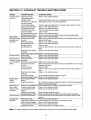
GUIDE
Problem
Possible Cause(s)
Corrective
Engine fails to start
Dirty air cleaner.
Fuel shut-off valveclosed(ifso
equipped).
Fuel tank empty,or stalefuel.
Refer to the engine manual packed with your unit.
Open fuel shut-off valve.
Engine runs erratic
Engine
overheats
Action
Fill tank with clean fresh gasoline. Fuel will not last over thirty
days unless a fuel stabilizer is used.
Choke not in ON position.
Move switch to ON position.
Blocked fuel line.
Clean fuel line.
Spark plug wire disconnected.
Connect wire to spark plug.
Faulty spark plug.
Clean, adjust gap or replace.
Unit running on CHOKE.
Move choke lever to OFF position.
Spark plug wire loose.
Connect and tighten spark plug wire.
Blocked fuel line or stale fuel.
Clean fuel line; fill tank with clean fresh gasoline. Fuel will not last
over thirty days unless a fuel stabilizer is used.
Drain fuel tank. Refill with fresh fuel.
Water or dirt in fuel system.
Dirty air cleaner.
Refer to the engine manual packed with your unit.
Carburetor out of adjustment.
Refer to the engine manual packed with your unit.
Engine oil level low.
Fill crankcase with proper oil.
Dirty air cleaner.
Refer to the engine manual packed with your unit.
Air flow restricted.
Stop engine and disconnect spark plug wire. Remove blower
housing and clean.
Carburetor not adjusted properly. Refer to the engine manual packed with your unit.
13
SECTION
12: HYDRAULIC
Trouble
Possible
Cylinder rod will
not move
Broken drive shaft.
Slow cylinder
shaft speed while
extending and
retracting
Leaking cylinder
Engine runs but
wood will not split,
or wood splits too
slowly
Engine stalls
during
splitting
Engine will not
turn or stalls
under low load
conditions
Will not split logs
]Leaking pump
ishaft seal
TROUBLE
Causes
Shipping plugs left in
hydraulic hoses.
Set screws in coupling not
adjusted properly.
Loose shaft coupling.
Gear sections damaged.
Damaged relief valve.
Hydraulic lines blocked.
Incorrect oil level.
Damaged directional valve.
Blocked directional valve.
Gear sections damaged.
Excessive pump inlet
vacuum.
Slow engine speed.
Damaged relief valve.
Incorrect oil level.
Contaminated oil.
Corrective
SHOOTING
GUIDE
Action
Return unit for authorized repair.
Disconnect hydraulic hoses, remove shipping plugs, reconnect hoses.
See operator's manual for correct adjustment.
Correct engine/pump alignment as necessary. See operator's manual.
Return unit for authorized repair.
Return unit for authorized repair.
Flush and clean hydraulic system.
Check oil level.
Return unit for authorized repair.
Flush and clean hydraulic system; return unit for authorized repair.
Return unit for authorized repair.
Make certain pump inlet hoses are clear and unblocked-use short, large
diameter inlet hoses.
Return unit for authorized
Return unit for authorized
Check oil level.
Drain oil, clean reservoir,
level.
Return unit for authorized
repair.
repair.
refill, make certain oil return tube is below oil
repair.
Directional valve leaking
internally.
Internally damaged cylinder, i Return unit for authorized repair.
Broken seals.
Return unit for authorized repair.
Scored cylinder.
Return unit for authorized repair.
Small gear section
Return unit for authorized repair.
damaged.
Pump check valve leaking.
Return unit for authorized repair.
Excessive pump inlet
Make certain pump inlet hoses are clear and unblocked; use short, large
diameter inlet hoses.
vacuum.
Incorrect oil level.
Check oil level.
Contaminated oil.
Drain oil, clean reservoir, refill, make certain oil return tube is below oil
level.
Directional valve leaking
Return unit for authorized repair.
internally.
Overloaded cylinder.
Do not attempt to split wood against the grain.
Internally damaged cylinder. Return unit for authorized repair.
Low horsepower/weak
Return unit for authorized repair.
engine.
Overloaded cylinder.
Do not attempt to split wood against the grain. If engine stalls repeatedly,
take unit for authorized repair.
Engine/pump misalignment. Correct alignment as necessary. See operator's manual.
Frozen or seized pump.
Return unit for authorized repair.
Low horsepower/weak
Return unit for authorized repair.
engine.
Hydraulic lines blocked.
Flush and clean hydraulic system.
Blocked directional valve.
Flush and clean hydraulic system; return unit for authorized repair.
Reservoir fluid level low.
Check and fill reservoir tank as instructed in Operation section of this
manual.
Broken drive shaft.
Return unit for authorized repair.
Engine/pump misalignment. Correct alignment as necessary. See operator's manual.
!Return unit for authorized repair.
Gear sections damaged.
Poorly positioned shaft seal. Return unit for authorized repair.
Plugged oil breather.
Make certain reservoir is properly vented.
Note: For repairs beyond the minor adjustments above, contact your local authorized service dealer.
14
15
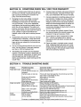
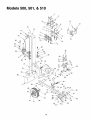
Models 500, 501, & 510
14
21
16
\
\
15
11
73
22
27
28
29
A
30
32
31
33
39
75
69
\
7O
67
/
72
'\
71
56
16
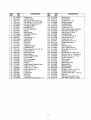
REF.
NO.
1
2
3
4
5
6
7
8
PART
NO.
781-0323B
712-0239
710-1018
736-0192
710-0459A
781-0356
781-0351
712-3001
750-0743
781-0537
781-0352A
781-0350A
736-0921
781-0168A
681-0093
714-0211
711-1135
718-0307
727-0471
727-0443
712-0130
726-0132
737-0153
737-0192
718-0481
737-0235
737-0306
723-0405
727-0502
714-0470
738-0805
732-0583
726-0214
781-0690
737-0236
681-0092A
710-0654A
,90
11
12
13
14
15
16
17
18
19
20
21
22
23
24
25
26
27
28
29
30
31
32
33
34
35
36
37
DESCRIPTION
Wedge Asm
Lock Nut 1/2-20
Hex Cap Screw 1/2-20 x 2.75
Flat Washer .531 x .93 x .090
Hex Cap Screw 3/8-24 x 1.5
Floating Gib Plate
Adjustable Gib
Hex Jam Nut 3/8-24
Spacer
Back Bracket
Adjustable Gib Shim
Fixed Gib
Lock Washer 1/2
Stripper Side
Beam Asm
Cotter Pin
Clevis Pin
Hydraulic Cylinder
Hydraulic Tube
Return Hose 3/4" I.D. x 44" Lg.
Lock Nut 3/8-16
Hose Clamp 5/8"
Return Elbow
90 ° Solid Male Adapter
Control Valve
3/4" Hose Adapter
Filter Housing
Oil Filter
High Pressure Hydraulic Hose
Cotter Pin 1/8" Dia.
Hinge Pin 1/2 x 4.8" Lg.
Comp. Spring 4" Lg.
Push Cap
Locking Rod
Pipe Plug
Frame Asm
Hex Washer Screw 3/8-16 x 1.0
REF.
NO.
38
39
40
41
42
43
44
45
46
47
48
49
50
51
52
53
54
55
56
57
58
59
60
61
62
63
64
65
66
67
68
69
70
71
72
73
75
17
PART
NO.
735-0256
726-0174
714-0122
718-0686
719-0353
712-0123
736-0119
781-0097
710-1338
718-0683
737-0329
710-0521
712-0798
736-0169
710-0411
681-0110
781-0680A
736-0185
712-0375
711-0813
732-0194
750-0497
710-0944
736-0262
713-0433
727-0311
781-0162
721-0168
741-0987
634-0186
634-0188
736-0351
712-0359
714-0162
734-0873
710-3144
736-0116
DESCRIPTION
Suction Hose
Hose Clamp
Sq.-Key 3/16" x .75"
Flexible Coupling
Coupling Shield
Hex Nut 5/16-24
L-Wash. 5/16" I.D.*
Rear Coupling Support Bracket
Hex Screw 5/16-24 x 3.25
Gear Pump (11 GPM)
45 Degree Elbow
Hex Bolt 3/8-16 x 3" Lg.
Hex Nut 3/8-16 Thd.*
L-Wash. 3/8" I.D.*
Hex Bolt 3/8-16 x 4" Lg.
Support Beam Asm
Tube
Flat Washer 3/8
Hex L-Nut 3/8-16 Thd.
Clevis Pin 5/16 x 2.5" Lg.
Spring Pin
Spacer 3/8" I.D. x .625" O.D.
Hex Bolt 3/8-16 x 4" Lg. (Grd 5)
FI-Wash. 3/8" I.D. x .87" O.D.
Chain--Tow Hitch
Hitch Coupler
Jack Stand
Bearing Seal Only
Bearing Cone
Wheel Assembly
Rim Assembly
FI-Wash..76" I.D. x 1.5" O.D.
Slotted Nut 3/4-16 Thd.
Cotter Pin 5/32" Dia. x 1-1/4" Lg.
Hub Cap
Hex Cap Screw 3/8-16 x 2.0
Flat Washer .635 ID x .93 OD
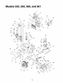
Models 530, 550, 560, and 561
®
15
19
5
18
22
48
A
33
j47
37_
40
\
\
46
C
38_
39
55
45
35
74
78
64
\
;6 68
\
42
79
58
"76
/
8_
8O
57
77
72
65
18
71
_EF.
NO.
1
2
3
4
5
6
7
8
9
10
11
12
13
14
15
16
17
18
19
20
21
22
23
24
25
26
27
28
29
3O
31
32
33
34
35
36
37
38
39
40
41
PART
NO.
781-0323B
712-0239
710-1018
736-0192
710-0459A
781-0356
781-0351
712-3001
i750-0750
i781-0537
781-0352A
781-0350A
736-0921
712-0239
781-0168A
712-0130
710-0859
681-0126
714-0211
711-1135
718-0306
727-0471
727-0443
726-0132
737-0153
737-0192
718-0481
737-0235
737-0306
723-0405
727-0502
714-0470
738-0805
726-0214
732-0583
736-0116
781-0690
737-0236
681-0092A
681-0138
710-0157
DESCRIPTION
Wedge Asm
Lock Nut 1/2-20
Hex Cap Screw 1/2-20 x 2.75
Flat Washer .531 x .93 x .090
Hex Cap Screw 3/8-24 x 1.5
Floating Gib Plate
Adjustable Gib
Hex Jam Nut 3/8-24
Spacer
Back Bracket
Adjustable Gib Shim
Fixed Gib
Lock Washer 1/2
Lock Nut 1/2-20
Stripper Side
Lock Nut 3/8-16
Hex Cap Screw 3/8-16 x 2.5
Beam Asm
Cotter Pin
Clevis Pin
Hydraulic Cylinder
Hydraulic Tube
Return Hose 3/4" ID x 44" Lg
Hose Clamp 5/8"
Return Elbow
90 Degree Solid Male Adapter
Control Valve
3/4" Hose Adapter
Filter Housing
Oil Filter
High Pressure Hydraulic Hose
Cotter Pin 1/8" Dia
Hinge Pin 1/2 x 4.8" Lg.
Push Cap
Comp. Spring 4" Lg.
Flat Washer .635 ID x .93 OD
Locking Rod
Pipe Plug
Frame Asm
Fender Asm 1
Hex Cap Screw 5/16-24 x .75
REF.
NO.
42
43
44
45
46
47
48
49
5O
51
52
53
54
55
56
57
58
59
60
61
62
63
64
65
66
67
68
69
70
71
72
73
74
75
76
77
78
79
8O
81
1"If E( uipped
19
PART
NO.
736-0159
736-0119
712-0123
710-0654A
726-0174
735-0256
710-1338
714-0122
718-0686
719-0353
736-0119
712-0123
781-0O97
718-0683
737-0329
710-0521
712-0798
736-0169
710-0411
781-0690
681-0110
781-0680A
736-0185
712-0375
711-0813
732-0194
750-0497
710-0944
736-0262
713-0433
727-0311
781-0162
721-0168
741-0987
634-0186
634-0180
736-0351
712-0359
714-0162
734-0873
DESCRIPTION
5/16 Washer
Lock Washer 5/16
Hex Nut 5/16-24
Hex Washer Screw 3/8-16 x 1.0
Hose Clamp
Suction Hose
Hex Screw 5/16-24 x 3.25
Sq. Key 3/16" x .75
Flexible Coupling
Coupling Shield
L-Washer 5/16" ID
Hex Nut 5/16-24
Rear Coupling Support Bracket
Gear Pump (11 gpm)
45 Degree Elbow
Hex Bolt 3/8-16 x 3" Lg.
Hex Nut 3/8-16
L-Washer 3/8" ID
Hex Bolt 3/8-16 x 4" Lg.
Locking Rod
Support Beam Asm
Tube
Flat Washer 3/8
Hex Lock Nut 3/8-16
Clevis Pin 5/16 x 2.5"
Spring Pin
Spacer 3/8" ID x .625' OD
Hex Bolt 3/8-16 x 4" Lg.
Flat Washer 3/8" ID x .87" OD
Chain - Tow Hitch
Hitch Coupler
Jack Stand
Bearing Seal Only
Bearing Cone
Wheel Assembly
Rim Assembly
Flat Washer .76" ID x 1.5" OD
iSIotted Nut 3/4-16
Cotter Pin 5/32" x 1-1/4" Lg.
Hub Cap
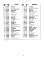
MANUFACTURER'S
LIMITED WARRANTY
FOR:
YARDMACHINESr)#
The
limited warranty
set forth below is given by MTD
PRODUCTS INC ("MTD") with respect to new merchandise
purchased and used in the United States, its possessions
and territories.
MTD warrants this product against defects in material and
workmanship for a period of two (2) years commencing on
the date of original purchase and will, at its option, repair or
replace, free of charge, any part found to be defective in
material or workmanship. This limited warranty shall only
apply if this product has been operated and maintained in
accordance with the Operator's Manual furnished with the
product, and has not been subject to misuse, abuse, commercial use, neglect, accident, improper maintenance,
alteration, vandalism, theft, fire, water or damage because
of other peril or natural disaster. Damage resulting from the
installation or use of any accessory or attachment not
approved by MTD Products Inc. for use with the product(s)
covered by this manual will void your warranty as to any
resulting damages.
b. Routine maintenance items such as lubricants, filters,
blade sharpening and tune-ups, or adjustments such
as brake adjustments, clutch adjustments or deck
adjustments; and normal deterioration of the exterior
finish due to use or exposure.
C. Log splitter
pumps, valves and cylinders have a separate one year warranty.
d. MTD does not extend any warranty for products sold
or exported outside of the United States of America,
its possessions and territories, except those sold
through MTD's authorized channels of export distribution.
No implied warranty, including any implied warranty of
merchantability
or fitness for a particular purpose,
applies after the applicable period of express written
warranty above as to the parts as identified.
No other
express warranty or guaranty, whether written or oral,
except as mentioned above, given by any person or
entity, including a dealer or retailer, with respect to any
product shall bind MTD. During the period of the Warranty, the exclusive remedy is repair or replacement
Normal wear parts or components thereof are subject to
separate terms as follows: All normal wear part or component failures will be covered on the product for a period of
90 days regardless of cause. After 90 days, but within the
two year period, normal wear part failures will be covered
ONLY IF caused by defects in material or workmanship of
OTHER component parts. Normal wear parts and components include, but are not limited to, belts, blades, blade
adapters, grass bags, rider deck wheels, seats, snow
thrower skid shoes, shave plates and tires. Batteries are
covered by a 90-day limited replacement warranty.
HOW TO OBTAIN SERVICE: Warranty service is available,
WITH PROOF OF PURCHASE THROUGH YOUR LOCAL
AUTHORIZED SERVICE DEALER. To locate the dealer in
your area, please check for a listing in the Yellow Pages or
contact the Customer Service Department of MTD PRODUCTS INC by calling 1-800-800-7310 or writing to P.O. Box
368022, Cleveland, Ohio 44136-9722. No product returned
directly to the factory will be accepted unless prior written
permission has been extended by the Customer Service
Department of MTD PRODUCTS INC.
This limited warranty does not provide coverage in the
following cases:
a.The engine or component parts thereof. These items
carry a separate manufacturer's warranty. Please refer
to the applicable manufacturer's warranty on these
items.
of
the product as set forth above. (Some states do not
allow limitations on how long an implied warranty lasts, so
the above limitation may not apply to you.)
The provisions as set forth in this Warranty provide the
sole and exclusive remedy arising from the sales. MTD
shall not be liable for incidental or consequential
loss
or damages including, without limitation, expenses
incurred for substitute or replacement lawn care services, for transportation or for related expenses, or for
rental expenses to temporarily replace a warranted
product. (Some states do not allow the exclusion or limitation of incidental or consequential damages, so the above
exclusion or limitation may not apply to you.)
In no event shall recovery of any kind be greater than the
amount of the purchase price of the product sold. Alteration
of the safety features
ranty. You assume the
injury to you and your
property arising out of
the product.
of the product shall void this Warrisk and liability for loss, damage, or
property and/or to others and their
the use or misuse or inability to use
This limited warranty shall not extend to anyone other than
the original purchaser, original lessee or the person for
whom it was purchased as a gift.
How State Law Relates to this Warranty: This limited
warranty gives you specific legal rights, and you may also
have other rights which vary from state to state.