1
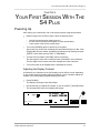
ALESIS
S4 Plus
Reference Manual
Introduction
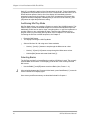
Thank you for purchasing the Alesis S4 Plus 64 Voice Sound Module. To take full
advantage of the S4 Plus’s functions, and to enjoy long and trouble-free use, please
read this user’s manual carefully.
How To Use This Manual
This manual is divided into the following sections describing the various modes of the
S4 Plus. Though we recommend you take time to read through the entire manual
once carefully, those having general knowledge about synthesizers should use the
table of contents and index to reference specific functions while using the instrument.
If you’ve upgraded your S4 to the new 2.0 “Plus” software, refer to Appendix D to find
out about the many new features.
Chapter 1: Setting Up. Deals with the necessary preparation before playing,
including connections to external devices.
Chapter 2: Your First Session with the S4 Plus. This section provides a brief tour
of the S4 Plus, shows you how to audition the various sounds of the S4 Plus, and
points out the various performance features.
Chapter 3: Connections. Details rear panel connections (like MIDI, footpedals and
the optical digital interface), proper hook-up procedures, plus application examples.
Chapter 4: Overview. Covers the structure of sound sources within the S4 Plus, how
to read and navigate through the LCD display pages, how to edit parameters, and
how to store edited Programs, Mixes and Effects.
Chapter 5: Editing Mixes. Explains how to create and edit Mixes.
Chapter 6: Editing Programs. How to create and edit Programs.
Chapter 7: Editing Effects. How to create and edit Effects Patches.
Chapter 8: Global Settings. Describes all global functions, such as Master Tuning,
Display Contrast, Keyboard Mode, Edit Mode and 48 kHz Clock In.
Chapter 9: MIDI Transfer and Storage Operations. Discusses MIDI functions and
how to store sounds either to a MIDI device or to a RAM card.
Appendices. MIDI basics, trouble-shooting, maintenance and service information,
MIDI Implementation Chart and an Index.
Conventions
The buttons, knobs, and rear panel connectors are referred to in this manual just as
their names appear on the S4 Plus, using all capital letters and in brackets ( Example:
[PROGRAM] button, MIDI [¨] and [Æ] buttons, Quad Knob [1], etc.). When text from
the S4 Plus’s display is quoted, it is indicated by a set of quotation marks ( Example:
“EDITING: SOUND 4”) .
J
When something important appears in the manual, an icon (like the one on the left)
will appear in the left margin. This symbol indicates that this information is vital when
operating the S4 Plus.
S4 Plus Reference Manual
1
Index
CONTENTS
1: Setting Up ...................................................................................................... 7
Unpacking and Inspection.............................................................................................. 7
AC Power ....................................................................................................................... 7
Line Conditioners and Protectors ................................................................ ...... 8
About Audio Cables ....................................................................................................... 9
Basic Audio Hookup....................................................................................................... 9
A Word About Sound Bridge .......................................................................................... 10
2: Your First Session With The S4 Plus ............................................................ 11
Powering Up................................................................................................................... 11
Adjusting the Display Contrast .......................................................................... 11
Playing the Demo Sequence............................................................................. 12
Enabling General MIDI Mode ......................................................................................... 12
Playing the S4 Plus ........................................................................................................ 13
Program Mode and Mix Mode ........................................................................... 13
Auditioning Internal Programs ........................................................................... 14
Selecting Banks ................................................................................................ 14
Selecting the MIDI Channel .............................................................................. 14
Realtime Performance Functions ................................................................ ...... 15
The Quad Knobs ............................................................................................... 15
Auditioning Mix Play Mode ................................................................................ 16
Selecting Banks ................................................................................................ 16
Editing a Mix ................................................................................................ ...... 17
Setting the Effects Level ................................................................................... 18
3: Connections................................................................................................... 19
Basic MIDI Hookup ........................................................................................................ 19
Using the S4 in Live Performance .................................................................................. 20
Using an External Sequencer ........................................................................................ 21
Digital Audio/Optical Hookup ......................................................................................... 22
Recording Digital Audio..................................................................................... 22
48 kHz Clock In .............................................................................................................. 22
4: Overview........................................................................................................ 23
Basic Architecture .......................................................................................................... 23
S4 Plus Polyphony .........................................................................................................23
Modes ............................................................................................................................ 24
Program Play Mode...........................................................................................24
Mix Play Mode .................................................................................................. 24
Program Edit Mode ...........................................................................................24
Mix Edit Mode ....................................................................................................25
Effects Edit Mode .............................................................................................. 25
Global Edit Mode .............................................................................................. 25
Store Mode ....................................................................................................... 25
Compare Mode ................................................................................................. 25
The User Interface: Display, Functions, Pages, and Parameters .................................. 26
About the Display .............................................................................................. 26
MIDI Buttons ..................................................................................................... 27
Quad Knob Editing ............................................................................................ 27
Parameter Editing ............................................................................................. 28
Editing Program Parameters............................................................................. 29
Edit 4 and Edit 1 Modes .................................................................................... 30
Resetting a Parameter Value ............................................................................ 30
Comparing Edited and Stored Versions .........................................................................31
Preset Memory and User Memory ................................................................................. 31
S4 Plus Reference Manual
3
Index
Storing ............................................................................................................................ 32
Store a Program ................................................................................................ 32
Copying Effects Between Programs .................................................................33
Store an Effect .................................................................................................. 33
Store a Mix ........................................................................................................ 33
To Audition Programs Before Storing................................................................ 34
5: Editing Mixes ................................................................................................. 37
What is a Mix? ............................................................................................................... 37
Mix Edit Mode ................................................................................................................ 37
Understanding the Edit Buffers ...................................................................................... 38
Program Assign for each MIDI Channel .........................................................................39
Level Setting for Each Program ..................................................................................... 39
Pitch ...............................................................................................................................40
Setting the Range and MIDI Switches ........................................................................... 40
Effects in Mix Play Mode ................................................................................................ 42
Effect Level ....................................................................................................... 42
Effect ................................................................................................................. 42
Naming a Mix ................................................................................................................. 43
Polyphony in Mix Play Mode .......................................................................................... 43
Playing a Group of Channels in a Mix ............................................................................ 44
6: Editing Programs ........................................................................................... 45
Overview ........................................................................................................................ 45
The “Normalized” Synth Voice ....................................................................................... 45
How the S4 Generates Sound ....................................................................................... 46
Program Sound Layers .................................................................................................. 46
S4 Plus Signal Flow ....................................................................................................... 47
The Four Sounds of a Program .........................................................................47
Lowpass Filter ................................................................................................... 48
Amp ................................................................................................................... 49
About Modulation ........................................................................................................... 49
Envelopes .........................................................................................................50
About Signal Processing ................................................................................................ 50
Drum Mode .................................................................................................................... 51
Program Edit Functions.................................................................................................. 52
Assign Voice ..................................................................................................... 52
Level .................................................................................................................. 54
Effect Level ....................................................................................................... 54
Pitch .................................................................................................................. 54
Filter .................................................................................................................. 57
Amp ................................................................................................................... 59
Range................................................................................................................ 60
Mod ................................................................................................................... 62
Pitch LFO .......................................................................................................... 65
Amp LFO ........................................................................................................... 68
Pitch Envelope .................................................................................................. 69
Filter Envelope .................................................................................................. 72
Amp Envelope................................................................................................... 74
Name ................................................................................................................ 78
Misc. ..................................................................................................................79
Programming Drum Sounds ...........................................................................................80
Assign Voice ..................................................................................................... 80
Level .................................................................................................................. 80
Effects Level................................................................................................ ...... 81
Pitch .................................................................................................................. 81
Filter .................................................................................................................. 81
Amp ................................................................................................................... 81
Range................................................................................................................ 82
4
S4 Plus Reference Manual
Index
Amp Envelope................................................................................................... 82
Copying Sounds .............................................................................................................83
Copying Effects .............................................................................................................. 83
Initializing Programs ....................................................................................................... 84
7: Editing Effects................................................................................................ 85
About Signal Processing ................................................................................................ 85
Selecting Effects in Mix Mode ........................................................................................ 86
Setting Effects Send Levels ...........................................................................................86
Editing Effects ................................................................................................................ 87
Storing Effect Patches In Program Mode ....................................................................... 88
Storing Effect Patches in Mix Mode ............................................................................... 88
Copying Effect Patches .................................................................................................. 89
Configurations ................................................................................................................ 89
Reverb............................................................................................................................ 96
Delay .............................................................................................................................. 101
Pitch ...............................................................................................................................102
Mod ................................................................................................................................ 106
Mix .................................................................................................................................107
Misc. ...............................................................................................................................108
EQ ..................................................................................................................... 108
Overdrive........................................................................................................... 108
8: Global Settings .............................................................................................. 111
Editing Global Parameters ............................................................................................. 111
LCD Contrast ................................................................................................................. 111
General MIDI Mode........................................................................................................ 111
Enabling General MIDI Mode via MIDI.............................................................. 111
Master Pitch and Master Tuning .................................................................................... 112
Mix Group Channel ........................................................................................................ 112
Controllers A – D ............................................................................................................ 112
Reset Controllers A – D .................................................................................................113
Controller Pedal 1 and 2 Assignment ............................................................................. 113
MIDI Program Select ...................................................................................................... 114
Receiving and Transmitting Bank Change Message ........................................ 114
Edit Mode ....................................................................................................................... 115
48 KHz Clock Input ........................................................................................................ 115
9: MIDI Transfer And Storage Operations ......................................................... 117
Saving the User Bank to an External Card .................................................................... 117
Loading a Bank from an External Card .......................................................................... 117
Storing an Individual Program or Mix to an External Card ............................................. 118
Loading an Individual Program or Mix from an External Card ....................................... 118
Card Storage RAMifications .............................................................................. 119
Saving Programs via MIDI Sys Ex ................................................................................. 119
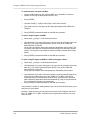
Appendix A: Trouble-Shooting........................................................................... 121
Trouble-Shooting Index .................................................................................................. 121
Re-initializing .................................................................................................................. 121
Checking Software Version ............................................................................................ 122
Maintenance/Service................................................................................................ ...... 122
Cleaning ............................................................................................................ 122
Maintenance...................................................................................................... 122
Warranty Information......................................................................................... 122
Obtaining Repair Service ..................................................................................122
Appendix B: MIDI Supplement .......................................................................... 125
MIDI Basics .................................................................................................................... 125
MIDI Hardware ............................................................................................................... 125
MIDI Message Basics ....................................................................................................126
S4 Plus Reference Manual
5
Index
Channel Messages: Mode Messages ............................................................... 126
Channel Messages: Voice Messages ............................................................... 126
System Common Messages ............................................................................. 128
General MIDI ..................................................................................................................128
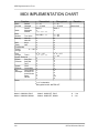
MIDI Implementation Chart ............................................................................................ 130
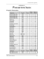
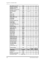
Appendix C: Parameters Index.......................................................................... 131
Program Parameters ...................................................................................................... 131
Mix Parameters .............................................................................................................. 133
Appendix D: What’s New in the 2.0 “Plus” Upgrade .......................................... 135
INDEX ............................................................................................................... 155
6
S4 Plus Reference Manual
Setting Up: Chapter 1
CHAPTER 1
SETTING UP
Unpacking and Inspection
Your S4 Plus was packed carefully at the factory. The shipping carton was designed
to protect the unit during shipping. Please retain this container in the highly unlikely
event that you need to return the S4 Plus for servicing.
Upon receiving the S4 Plus, carefully examine the shipping carton and its contents for
any sign of physical damage that may have occurred in transit. If you detect any
damage, do not destroy any of the packing material or the carton, and immediately
notify the carrier of a possible claim for damage. Damage claims must be made by
you. Contact your Alesis dealer.
The shipping carton should contain the following items:
•
•
•
•
•
J
S4 Plus with the same serial number as shown on shipping carton
AC Power Supply
Computer floppy disk containing Sound Bridge software and electronic manual
This instruction manual, plus lists of Mixes and Programs, and Quick Start guide
Alesis warranty card
It is important to register your purchase; if you have not already filled out your
warranty card and mailed it back to Alesis, please take the time to do so now.
AC Power Hookup
The S4 Plus works with the voltage of the country it is shipped to (either 110 or 220V,
50 or 60 Hz), and comes with a line cord or power supply suitable for the destination
to which the keyboard is shipped.
Check the label on the AC adapter to ensure that the “input voltage” is correct for
your area. Insert the AC adapter's smaller plug into the 9V AC Power jack on the S4
Plus’s rear panel. Then plug the AC adapter itself into a source of AC power,
preferably a power strip with its own on/off switch. Alesis recommends turning off
power to the supply or unplugging it when the S4 Plus is not in use, to prolong its life.
Use only the AC adapter supplied with the S4 Plus; use of any other adapter will void
your warranty.
J
Alesis cannot be responsible for problems caused by using the S4 Plus or any
associated equipment with improper AC wiring.
S4 Plus Reference Manual
7
Chapter 1: Setting Up
Line Conditioners and Protectors
Although the S4 Plus is designed to tolerate typical voltage variations, in today’s
world the voltage coming from the AC line may contain spikes or transients that can
possibly stress your gear and, over time, cause a failure. There are three main ways
to protect against this, listed in ascending order of cost and complexity:
•
Line spike/surge protectors. Relatively inexpensive, these are designed to protect
against strong surges and spikes, acting somewhat like fuses in that they need to
be replaced if they’ve been hit by an extremely strong spike.
•
Line filters. These generally combine spike/surge protection with filters that
remove some line noise (dimmer hash, transients from other appliances, etc.).
•
Uninterruptible power supply (UPS). This is the most sophisticated option. A UPS
provides power even if the AC power line fails completely. Intended for computer
applications, a UPS allows you to complete an orderly shutdown of a computer
system in the event of a power outage, and the isolation it provides from the
power line minimizes all forms of interference—spikes, noise, etc.
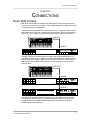
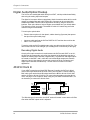
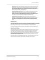
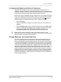
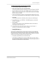
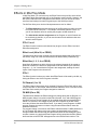
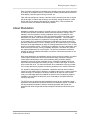
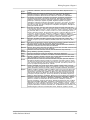
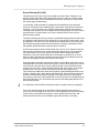
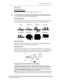
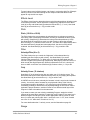
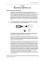
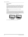
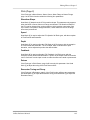
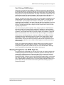
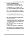
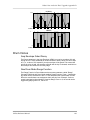
MIDI Keyboard
OUTPUTS
POWER
9 VAC~
THRU
OUT
MIDI
IN
48 KHZ IN
DIGITAL OUT
L
R
AUX
L
R
PHONES
MAIN
1/4" Audio Cables
AC Receptacle
Stereo Headphones
Stereo Amp
8
S4 Plus Reference Manual
Setting Up: Chapter 1
About Audio Cables
The connections between the S4 Plus and your studio are your music’s lifeline, so
use only high quality cables. These should be low-capacitance shielded cables with a
stranded (not solid) internal conductor and a low-resistance shield. Although quality
cables cost more, they do make a difference. Route cables to the S4 Plus correctly
by observing the following precautions:
•
Do not bundle audio cables with AC power cords.
•
Avoid running audio cables near sources of electromagnetic interference such as
transformers, monitors, computers, etc.
•
Do not place cables where they can be stepped on. Stepping on a cable may not
cause immediate damage, but it can compress the insulation between the center
conductor and shield (degrading performance) or reduce the cable’s reliability.
•
Avoid twisting the cable or having it make sharp, right angle turns.
•
Never unplug a cable by pulling on the wire itself. Always unplug by firmly
grasping the body of the plug and pulling directly outward.
•
Although Alesis does not endorse any specific product, chemicals such as Tweek
and Cramolin, when applied to electrical connectors, are claimed to improve the
electrical contact between connectors.
Basic Audio Hookup
J
When connecting audio cables and/or turning power on and off, make sure that all
devices in your system are turned off and the volume controls are turned down.
Because the S4 Plus includes extensive signal processing as well as a full
complement of sounds, you can make great sounds with nothing more than an
amplifier or a set of headphones.
The S4 Plus has two Main and two Aux audio outputs. These can provide an
amplification system or mixer with several different audio hookup options:
•
Mono. Connect a mono cord from the [MAIN–R] Audio Output to a mono
amplification system or individual mixer input.
•
Stereo. Connect two mono cords from the [MAIN–L] and [MAIN–R] Audio
Outputs to a stereo amplification system or two mixer inputs.
•
Dual Stereo/Four Individual Outs. Connect two mono cords from the [MAIN–L]
and [MAIN–R] Audio Outputs and two mono cords from the [AUX–L] and [AUX–
R] Outputs to a dual stereo amplification system, or four mixer inputs.
•
Stereo Headphones. Plug a set of high-quality stereo headphones into the rear
panel [PHONES] jack.
S4 Plus Reference Manual
9
Chapter 1: Setting Up
A Word About Sound Bridge
Included with the S4 Plus is a 3-1/2" floppy disk containing a software program called
Sound Bridge. This software has been provided free of charge in an effort to promote
sound design for the S4 Plus.
Sound Bridge is a Macintosh™ sound development utility which compiles custom
samples from a variety of sources into the S4 Voice format, and downloads the
compiled data to an Alesis PCMCIA Sound Card via MIDI Sysex to an S4 Plus or S4
Plus. Originally developed for in-house use only, Alesis soon realized the need for
individuals and sound developers to be able to burn their own Sound Cards as well,
using whatever samples they wanted. Sound Bridge makes this possible without
having a PCMCIA card burner attached to your computer. All you need is an S4 Plus
or S4 Plus.
Sound Bridge creates an S4 Voice (multi-sample) by loading Sample Cell I or Sample
Cell II format Instrument files. Using this format, Sound Bridge is able to determine
key group and velocity group split points, root notes, sample playback rates, tunings,
start points, loop points, and loop tunings. Sound Bridge can also create S4 Voices
without Sample Cell Instruments by loading single AIFF, Sound Designer, or Sound
Designer II files.
Sound Bridge does NOT require Sample Cell hardware. The Sample Cell Instrument
file, or sample file, may be loaded directly into Sound Bridge from any disk (i.e. CDROM, floppy disk, hard disk, etc.). For example, a user may load data from a Sample
Cell CD-ROM, and send this data to the S4 PCMCIA Card, without ever using
Sample Cell!
Sound Bridge can write to PCMCIA cards (or PC Cards) of up to 8MB in size. These
cards must be either Type I SRAM (150ns or faster) or Type I Flash RAM cards
(AMD C-series or D-series 5V Flash Memory Cards). If you are unsure whether a
card is compatible with the S4 Plus, contact Alesis Product Support for more
information.
The Sound Bridge disk contains the Sound Bridge application, and an electronic
manual which will give you all the information you need to know to run Sound Bridge.
10
S4 Plus Reference Manual
Your First Session With The S4 Plus: Chapter 2
CHAPTER 2
YOUR FIRST SESSION WITH THE
S4 PLUS
Powering Up
After making your connections, turn on the system’s power using this procedure:
¿ Before turning on the S4 Plus’s power, check the following items:
•
•
•
¡
Have all connections been made correctly?
Are the volume controls of the amplifier or mixer turned down?
Is the volume of the S4 Plus turned down?
Turn on the [POWER] switch on the S4 Plus front panel.
Upon power-up, the S4 Plus will display the last selected Program or Mix. If this
Program/Mix has been edited, the display will indicate this by showing the word
“EDITED ” below either the word “MIX ” or “PROGRAM .”
¬ Turn the S4 Plus’s master [VOLUME] control to maximum.
The best signal-to-noise ratio is achieved when [VOLUME] is set to maximum.
This is a digital volume control, and lower settings have lower resolution.
÷ Turn on the power of the amplifier/mixer, and adjust the volume.
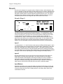
Adjusting the Display Contrast
Occasionally, the characters in the LCD display may be difficult to read, depending
on the viewing angle and existing lighting conditions. In such a situation, adjust the
contrast of the LCD display using the following procedure.
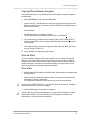
¿ Press [GLOBAL].
The display will change to the Global Page.
¡
Use Quad Knob [1] to adjust the contrast, or use the VALUE [¨] and [Æ] buttons.
The contrast and its value in the display will change.
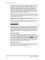
MIDI
CHAN
1
PROG
PRESET
1
PAGE: 1 2 3 4 5 6 7
S4 Plus Reference Manual
GLOBAL
VALUE
11
Chapter 2: Your First Session With The S4 Plus
Playing the Demo Sequence
The S4 Plus has a built-in demo sequence which demonstrates the wide variety of
sounds this amazing instrument is capable of generating. In order to get the full effect
of the demo, we recommend that you connect both the LEFT and RIGHT outputs to
your sound system, or listen on headphones.
To play the demo sequence:
¿ Hold the [GLOBAL] button, and press [MIX].
The upper-right display will read “Playing Demo. Press MIX to stop.”
¡
Press [MIX] to stop the demo.
There will be no MIDI OUT messages during the demo, and the keyboard will be
disabled.
Playing Specific Sections of the Demo
The demo sequence is currently comprised of four sections. Any of these sections
can be played directly, without listening to the sections preceding it. This can be done
by holding [GLOBAL] and pressing one of the Quad Buttons [1] – [4] buttons which
corresponds to the section you would like to hear.
Enabling General MIDI Mode
If you are using a General MIDI sequencer, and/or playing a sequence that is
programmed to take advantage of General MIDI, turn the “General MIDI” function in
the S4 on.
To turn the General MIDI function on:
¿ Press [GLOBAL].
The display will now be in Global Edit Mode.
¡
Press Quad Button [2].
This selects the General MIDI parameter in the display.
¬ Press the VALUE [Æ] button.
This turns on General MIDI mode, and automatically puts you into Mix Play Mode
with Mix 00 of Preset Bank 4 selected.
For more information about General MIDI, refer to the the MIDI Supplement in
Appendix B.
12
S4 Plus Reference Manual
Your First Session With The S4 Plus: Chapter 2
Playing the S4 Plus
The S4 Plus is shipped from the factory with 5 Banks of 128 Preset Programs
(sounds) each. Additionally, there are 100 Mixes in each of the 5 Banks.
Program Mode and Mix Mode
The S4 Plus is always in one of two modes: Program Mode or Mix Mode. When
selecting Programs, you will be in Program Play Mode. When editing a Program, you
will use Program Edit Mode. When auditioning Mixes, you will be in Mix Play Mode.
When editing a Mix, you will use Mix Edit Mode.
J
If you ever get lost while programming the S4 Plus, press either the [PROGRAM]
button or the [MIX] button to get back to their respective play modes.
•
Press the [PROGRAM] button to select Program Play Mode.
In Program Play Mode, the S4 Plus plays a single Program. The display will look like
this:
MIDI
CHAN
1
PROG
PRESET
The current PROGram number is displayed, and the Program’s name appears in the
top-right. The current Bank is shown to the left of the Program name. The current
MIDI channel is shown in the top left corner left.
•
Press the [MIX] button to select Mix Play Mode.
In Mix Play Mode, the S4 Plus can combine up to 16 Programs for stacking sounds
together, splitting your keyboard controller into different regions, or working with a
MIDI sequencer. The display will look like this:
MIDI
CHAN
1234
MIX
PRESET
PROG
PRESET
EFFECT
PRESET
All MIDI channels that are active in the current Mix are shown at the top left, to
indicate multitimbral operation. The current MIX and EFFECT numbers are displayed,
along with the current Bank and Mix’s name. The PROGram number display shows
the program assigned to the underlined MIDI channel.
S4 Plus Reference Manual
13
Chapter 2: Your First Session With The S4 Plus
Auditioning Internal Programs
¿ Press the [PROGRAM] button to select Program Play Mode.
You can now play the S4 Plus keyboard; the Program will be whatever was
selected when last in Program mode (Program number 00 – 127).
¡
J
Select a Program using any of these methods:
•
Use the [-1] and [+1] buttons to step through the Programs one at a time.
•
Use the [-10] and [+10] buttons to step through the Programs ten at a time.
•
Hold the [PROGRAM] button and rotate Quad Knob [1] .
To hear the Stereo Grand Piano, select Program 00 in Preset Bank 1.
Selecting Banks
The S4 Plus provides five internal Banks containing 128 Programs in each (and 100
Mixes each, but we’ll get to Mixes in a moment). The currently selected Bank will be
shown in the display just to the left of the currently selected Program’s name.
•
Use the BANK [¨] and [Æ] buttons to select a Bank (User, Preset 1 – 4).
User and Preset Banks are described in detail in Chapter 4.
J
Selecting the MIDI Channel
While in Program Play Mode, the S4 Plus can transmit and receive information on
any single MIDI channel of the 16 available channels. The currently selected channel
appears at the top left of the display.
MIDI
CHAN
1
MIDI
PROG
PRESET
¿ Use the MIDI [¨] and [Æ] buttons to select a MIDI channel from 1 – 16.
The display will change to indicate the currently selected MIDI channel.
14
S4 Plus Reference Manual
Your First Session With The S4 Plus: Chapter 2
Realtime Performance Functions
The S4 Plus provides various ways to control the sound as you are playing. Try out
some of these functions while playing your MIDI keyboard. The sound of the effects
can also change by using these controllers. The effect of these realtime controllers
varies from Program to Program; in some they may not be active, and in others they
may have a dramatic effect.
•
•
•
•
•
Velocity. The volume and tonal quality of the sound will change according to how
hard you play the keyboard.
Aftertouch . The action of pressing a key down after playing it is called
“aftertouch” (it is also sometimes referred to as “Pressure” since it corresponds to
the amount of pressure being applied to the keyboard). Pitch, tone and volume
(among other things) can be changed using aftertouch.
Pitch Bend Wheel. While playing a note, you can move the PITCH BEND
WHEEL up to raise the pitch, or down to lower the pitch. The amount of pitch
bend available can be different for each Program.
Modulation Wheel. By raising the MODULATION WHEEL, you can add
expressive modulation effects (such as vibrato or tremolo) while you play. The
type of modulation effect can be different for each Program.
The Quad Knobs. These are described below.
Further expressive control is available with a pedal switch or expression pedal. By
using a sustain pedal connected to your master MIDI keyboard, you can have the S4
Plus’ sound sustain even after you release the keys. By connecting an expression
pedal to your master MIDI keyboard, you can use the pedal to change the volume or
tone (or some other quality such as reverb depth or vibrato speed) of the sound, if the
Program is edited to use the pedal(s).
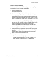
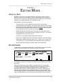
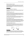
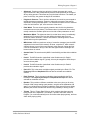
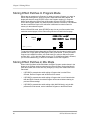
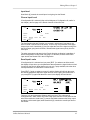
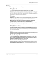
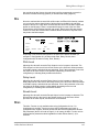
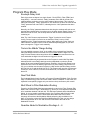
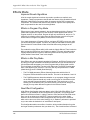
The Quad Knobs
To the right of the display are four knobs referred to as Quad Knobs, [1]—[4], each
with its own button. The Quad Knobs provide control over various parameters
depending on the mode you are in. The parameters in the display will change
depending on which function and page are selected. Not all four Quad Knobs are
active in all windows; there are many pages that have only one active Quad Knob.
In Program Play Mode and Mix Play Mode, the Quad Knobs act as Controllers A–D.
These Controllers are defined in Global Edit Mode (Page 3) to transmit various MIDI
controller messages. If a Program or Mix uses these Controllers A–D, a pair of
arrows will point towards the active controller’s letter in the display. This indicates that
moving the related Quad Knob will have some kind of effect on the selected Program
or Mix. In the illustration below, Controller A (Quad Knob [1]) is used by the selected
Program.
1
2
3
4
When in Program Edit Mode or Mix Edit , the Quad Knobs are linked to the
parameters that appear in the right side of the display. The lower line of the
alphanumeric display will show the abbreviated name of each parameter, with a bar
graph below it representing the current setting of the parameter. By turning Quad
S4 Plus Reference Manual
15
Chapter 2: Your First Session With The S4 Plus
Knob [1], you adjust the setting of the first parameter on the left. Turning Quad Knob
[2] adjusts the next parameter, and so on. Once a Quad Knob has been turned, or its
button has been pressed, the top line of the display will immediately show the
parameter’s name and current setting. At this point, the parameter will have a thick
underline beneath its bargraph, indicating that you can now use the VALUE [¨] and
[Æ] buttons to adjust the parameter’s setting.
Auditioning Mix Play Mode
Mix Play Mode allows you to assign a Program to each of the 16 MIDI channels. This
makes it easy to create multitimbral setups for use with an external MIDI sequencer.
Additionally, a MIX can be used to “layer” sounds together, or “split” the keyboard in a
number of ways, or any combination of these. There are many different ways to
program a Mix. For more about Mix Play Mode, refer to Chapter 5. For more about
connecting the S4 Plus to a MIDI sequencer, see Chapter 3.
¿ Press the [MIX] button.
The display will change to Mix Play Mode.
¡
Select a Mix from 00—99 using one of these methods:
•
Use the [-1] and [+1] buttons to step through the Mixes one at a time.
•
Use the [-10] and [+10] buttons to step through the Mixes ten at a time.
•
Hold the [MIX] button and rotate Quad Knob [1].
Selecting Banks
The S4 Plus provides five internal Banks containing 100 Mixes in each. The currently
selected Bank will be shown in the display just to the left of the currently selected
Mix’s name.
•
J
Use the BANK [¨] and [Æ] buttons to select a Bank (User, Preset 1 – 4).
After switching between the Preset and User banks, press Quad Button [1] to see the
name of the Mix in the display again.
User memory and Preset memory are described in detail in Chapter 4.
16
S4 Plus Reference Manual
Your First Session With The S4 Plus: Chapter 2
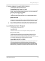
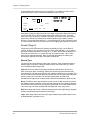
Editing a Mix
In this section, we will assign Programs to and set volume levels for the 16 MIDI
channels in a Mix, for playing back tracks from a MIDI sequencer. However, there is
much more about a Mix that may be edited. Refer to Chapter 5 for more about Mix
editing.
¿ Press [MIX] and select a Mix using one of the three methods described above.
¡
Press [SELECT].
The top line of the LCD’s function list will read “EDITING: MIX”.
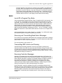
¬ Simultaneously press both the FUNCTION [¨] and [Æ] buttons.
MIDI
CHAN
1 2 3 4 5 6 7 8 9 10 11 12 13 14 15 16
MIX
PRESET
PROG
PRESET
EDITING:
MIX
PROGRAM – ASSIGN
PITCH
RANGE
EFFECT
PRESET
LEVEL
EFFECT–LEVEL
EFFECT NAME
PAGE: 1
÷ Use the MIDI [¨] and [Æ] buttons to select a MIDI channel for editing.
The MIDI monitor and selection strip will indicate the selected MIDI channel with
an underline. These buttons “wrap around” (e.g., if you’re on channel 16 and
press MIDI [Æ] , you’ll select channel 1. If channel 1 is selected and you press
MIDI [¨] , you’ll select channel 16).
ƒ Use Quad Knob [1] to choose a Bank (User, Preset 1 – 4).
ª
Use Quad Knob [2] to select a Program for the selected Channel.
D Use Quad Knob [4] to enable or disable the Program on the selected Channel.
When enabled, the Channel number will appear in the top left of the display.
When disabled, the Channel number will not appear (unless selected for editing
using the MIDI [¨] and [Æ] buttons, in which case it is underlined) .
« To set the Program’s level, press the FUNCTION [Æ] button once so that
“LEVEL” is underlined in the display. Use Quad Knob [1] to adjust the level.
» Repeat steps ¬ — « until all desired Programs are assigned to all desired MIDI
channels, and have the appropriate levels.
J
Changes to Mix parameters are temporary and will be lost if another Mix is selected.
To make changes permanent, you must store the Mix into the User bank. Refer to
Chapter 4 for information about storing changes.
S4 Plus Reference Manual
17
Chapter 2: Your First Session With The S4 Plus
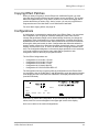
Setting the Effects Level
Each Program can use up to four Sounds, for either layering or splitting the keyboard.
Each of these Sounds has its own effects send level and effects bus assignment.
Many of the Programs in the S4 Plus use only one or two Sound layers, while others
may use all four Sounds. You can adjust the effect send amount for each Sound
independently, or you can view/edit all four sounds simultaneously.
¿ Press [PROGRAM] to access Program Play Mode, and select a Program you
wish to edit, using the methods described on page 14.
¡
Press [SELECT] to access Program Edit Mode.
¬ Press the [EFFECT] button (located among the DIRECT SELECT buttons on the
far left); the words “EFFECT - LEVEL” are underlined in the display.
This is where you determine how much level will be sent from the current
Program sound layer to the effects processor, and on which of the four busses.
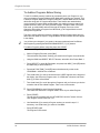
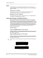
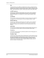
MIDI
CHAN
1
PROG
PRESET
EDITING:
PITCH
PLFO
PROGRAM SOUND 1
ASSIGN – VOICE
LEVEL
EFFECT–LEVEL
FILTER AMP
RANGE
MOD EFFECT NAME
FLFO
ALFO
PENV FENV AENV
TRACK
MISC.
PAGE: 1
÷ Turn Quad Knob [1] to adjust the effect send level of the selected Sound (1—4).
For the most dramatic effect, set this to 99.
ƒ Press the [EDIT 1] button to select another Sound to adjust.
The display will indicate “SOUND 1” or “SOUND 2,” etc., to indicate which of the
four Sounds is being edited.
ª
Press the [EDIT 4] button to display the effect send levels of all four Sounds
simultaneously; use Quad Knobs [1] — [4] to adjust each Sound’s effect level.
The display will indicate “SOUND 1 2 3 4.”
MIDI
CHAN
1
PROG
PRESET
EDITING:
PITCH
PLFO
PROGRAM SOUND 1 2 3 4
ASSIGN – VOICE
LEVEL
EFFECT–LEVEL
FILTER AMP
RANGE
MOD EFFECT NAME
FLFO
ALFO
PENV FENV AENV
TRACK
MISC.
PAGE: 1
Note: If a Sound is not enabled in a Program, its title will be shown in lowercase
(“snd4”), and adjusting its controls will have no effect on the Sound until the Sound is
enabled. To enable a Sound, hold down its respective Quadp Button (i.e., [3] for
Sound #3) and press VALUE [Æ].
18
S4 Plus Reference Manual
Connections: Chapter 3
CHAPTER 3
CONNECTIONS
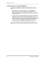
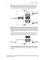
Basic MIDI Hookup
MIDI is an internationally-accepted protocol that allows musical-related data to be
conveyed from one device to another. See the MIDI Supplement in Appendix B if you
are not familiar with how MIDI works.
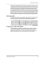
The MIDI connections provide three different functions. To trigger the S4 Plus from a
MIDI control device (such as a master keyboard, drum pad, guitar or bass controller,
sequencer, etc.), connect the control device’s MIDI OUT to the S4 Plus’ MIDI IN.
MIDI OUT
MIDI IN
The MIDI THRU jack carries a replica (or echo) of the signal appearing at the S4
Plus’ MIDI IN, allowing you to trigger other devices from the same controller which is
feeding the S4 Plus. Simply connect the S4 Plus’ MIDI THRU to the other device’s
MIDI IN. Note that the MIDI THRU jack will not send messages from the S4 Plus’
keyboard itself.
MIDI OUT
MIDI IN
MIDI THRU
MIDI IN
The MIDI OUT sends MIDI data from the S4 Plus to other MIDI devices. This can
include System Exclusive data (see the MIDI supplement) which can be sent to a
storage device such as a MIDI librarian software program for later recall, or to
transfer data to another S4 Plus.
S4 Plus Reference Manual
19
Chapter 3: Connections
Using the S4 in Live Performance
Depending on the capabilities of your MIDI controller keyboard, you have two
different options available for how the S4 Plus will respond when it is in Mix Play
Mode:
•
If your controller can only issue commands on one or two MIDI channels
simultaneously, you may want to set the S4 Plus’ “Mix Group Channel”
parameter (on page 2 of the Global display) to a channel between 1 and 16, so
that your controller can play a mix of several S4 Plus Programs in response to a
single channel of MIDI.
•
If you have a master controller or QuadraSynth which can send on multiple MIDI
channels, you may want to set the S4 Plus’ “Mix Group Channel” to “Off”. To
create layers or stacks, your controller must send multiple MIDI messages to the
S4 Plus simultaneously. This offers you the added control of changing the sound
from the controller by sending Program Change commands on individual
channels within a Mix. A disadvantage of this approach is that the controller
must send many channels of duplicate MIDI messages simultaneously.
Note: In Program Play Mode, the Mix Group Channel parameter has no effect. For
more information about the Mix Group Channel parameter, see pages 41, 44 and
112.
20
S4 Plus Reference Manual
Connections: Chapter 3
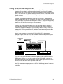
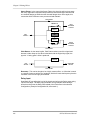
Using an External Sequencer
The MIDI keyboard or controller (such as the QuadraSynth Plus) can generate MIDI
signals that are recorded by a sequencer. On playback, the sequencer sends this
data back into the S4 Plus, which then serves as a multitimbral sound module (in Mix
Mode). The sequencer can generate data over several channels; in Mix Mode, the S4
Plus can be programmed so that individual Programs play sequenced data on
specific channels.
Example: If the sequencer transmits a piano part over channel 1, a bass part over
channel 2, and a drum part over channel 10, you could set up a S4 Plus Mix so that a
piano sound plays only the MIDI data assigned to channel 1, a bass sound plays only
the MIDI data assigned to channel 2, and drums play only the MIDI data assigned to
channel 10. The S4 Plus can store up to 100 User Mixes.
Connect your master keyboard’s MIDI Out to the sequencer’s MIDI In (if using a
computer-based sequencer, connect to the computer’s MIDI interface’s MIDI In).
Connect the sequencer’s MIDI Out to your keyboard’s MIDI In. Finally, connect your
keyboard’s MIDI Thru to the S4 Plus’s MIDI IN (the Thru signal carries a replica of
what appears at the keyboard’s MIDI In, which is the same as the sequencer’s MIDI
Out).
Note: It is not necessary to connect the S4 Plus’s MIDI OUT to the sequencer,
although doing so allows the S4 Plus to send data to the computer (such as System
Exclusive data to be stored into a librarian program).
COMPUTER
MIDI
INTERFACE
MIDI OUT
MIDI IN
MIDI IN
MIDI THRU
MIDI IN
If you are driving other MIDI gear (such as an expander module or MIDI-responsive
signal processor), you’ll usually drive these from the sequencer if it has additional
MIDI outputs. However, you can also use the S4 Plus’s MIDI THRU connector to
drive other modules since the Thru carries a replica of what appears at the S4 Plus’s
MIDI IN, which is the same as the sequencer’s MIDI OUT.
Note: For most sequencer applications, the S4 Plus’ “Mix Group Channel” parameter
(on page 2 of the Global display) should be set to OFF. See page 112 for more
information.
S4 Plus Reference Manual
21
Chapter 3: Connections
Digital Audio/Optical Hookup
The S4 Plus can send digital audio directly into ADAT, which provides better fidelity
than using the analog inputs and outputs.
The digital I/O connector follows a proprietary Alesis format that carries all four audio
outputs on a single fiber optic cable. Either pair of outputs can be converted into
standard AES/EBU or S/PDIF stereo digital audio format by using the Alesis AI-1
interface. Fiber optic cables of various lengths are available from your Alesis dealer.
The shorter the cable, the better. The model OC cable is 5 meters long and is the
maximum length recommended.
To hook up the optical cable:
¿ Remove the two pieces of clear plastic, tubular sleeving (if present) that protect
the tips of the optical cable plugs.
¡
Insert one cable end into the S4 Plus DIGITAL OUT and the other end into the
ADAT or AI-1 DIGITAL IN.
To test the cable and S4 Plus digital output, plug one cable end into the S4 Plus. The
other end should emit a soft red light (it is not dangerous to look directly at this light).
Recording Digital Audio
Once the fiber optic connection is made between the S4 Plus and ADAT or an AI-1 ,
the S4 Plus will output audio on the first four channels of the digital bus (the bus is
capable of handling eight channels of digital audio). The Main Left and Right outputs
are routed to channels 1 and 2, while the Aux Left and Right outputs are routed to
channels 3 and 4. Note that the volume knob controls the level of all analog and
digital output channels simultaneously. Set the volume to maximum for most
applications.
48 kHz Clock In
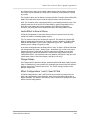
If your ADAT system has an Alesis BRC Remote Controller, the S4 Plus’s digital
clock must be synchronized to the clock coming from the BRC. Connect a BNC-toBNC cable (such as the Alesis BN cable) between the BRC’s 48 kHz CLOCK OUT
and the S4 Plus’s 48 kHz CLOCK IN. For more information about using the 48 kHz
clock, see page 118 in Chapter 8. When using only one ADAT without the BRC, it is
not necessary to connect the 48 kHz Clock.
SYNC
IN
48 KHZ
OUT
DIGITAL
IN
SYNC
OUT
ADAT #1
BRC
ADAT #2
DIGITAL
OUT
48 KHZ
IN
ADAT #3
Tip: With this type of connection, the ADAT tracks will remain in tune with the S4 Plus
even when the BRC’s pitch value is adjusted.
22
S4 Plus Reference Manual
Overview: Chapter 4
CHAPTER 4
OVERVIEW
Basic Architecture
The S4 Plus contains digitized acoustic and electronic voices, organized into 18
groups of sound types. The groups are:
Piano
Organ
Keyboard
Synth
Waves
Bass
Guitar
Brass
Woodwind
String
Ensemble
Ethnic
Voice
Sound FX
Drums
Percussion
Rhythm
QSPlus
Several functions (filter, amplitude envelope, pitch envelope, LFO, multiple
modulation sources, signal processors, etc.) can be used to process a sample. A
Sound is the combination of a sample with its associated processing.
A Program consists of up to four sounds. These sounds can be layered, split over
specific keyboard ranges, or selectively overlapped. The S4 Plus has a User Bank of
128 Programs that you can modify, plus 4 Preset Bank s with 512 Preset Programs
that are permanently installed in the S4 Plus at the factory (although the Preset
Programs can be edited, they must be stored into the User bank to permanently
retain your changes). Each Program is linked to its own Effects Patch.
A Mix consists of up to 16 Programs, each assigned to a specific MIDI channel and
one Effect Patch. The S4 Plus has 100 Mixes in the User Bank, plus 4 Preset Banks
with 400 Preset Mixes. This is extremely useful for multitimbral setups where the S4
Plus plays back different sounds on different MIDI channels. Because of the 64
voices and built-in effects, the S4 Plus is often the only sound generator needed.
S4 Plus Polyphony
The S4 Plus provides 64-voice polyphony (i.e., how many notes can play at once). If
a program uses one sound, up to 64 notes can play at once. Layering two sounds
allows for 32-note polyphony and layering four sounds, 16-note polyphony.
Layering is a powerful technique that allows you to build up complex timbres. This is
crucial because acoustic instruments have extremely complex, evolving sounds and
by comparison, many synths sound static. Being able to layer up to four sounds
allows for creating large ensembles (e.g., brass section consisting of alto & tenor sax,
trumpet, and trombone) or extremely realistic versions of single instruments. When
creating layered Programs, keep polyphony in mind. If all Programs in a Mix use all
four available sounds, the S4 Plus will quickly run out of voices.
S4 Plus Reference Manual
23
Chapter 4: Overview
Modes
The S4 Plus is always in one of two main modes: Program Mode or Mix Mode.
Pressing [PROGRAM] selects Program Play Mode, while pressing [MIX] selects Mix
Play Mode. While in Program Play Mode, you can press [SELECT] to access
Program Edit Mode and Effects Edit Mode. While in Mix Play Mode, pressing
[SELECT] alternates between Mix Edit Mode, Program Edit Mode and Effects Edit
Mode. Pressing [GLOBAL] accesses Global Edit Mode, pressing [COMPARE]
accesses Compare Mode, and pressing [STORE] accesses Store Mode. Here are
descriptions of these modes:
Program Play Mode
Program Play Mode lets you play the S4 Plus’s various Programs one at a time. The
S4 Plus contains 512 Preset and 128 User Programs (i.e., the sounds of various
instruments, effects, ensembles, etc.) that show off just how cool this instrument
really is. Initially, the 4 Preset Banks and the User Bank contain data loaded in at the
factory. The User Programs can be edited or replaced with your own Programs.
However, you cannot replace the Preset Programs, because these are stored in
ROM (permanent memory). In Program Play Mode, the S4 Plus responds to or
generates messages on a single MIDI channel.
Mix Play Mode
Mix Play Mode lets you audition the S4 Plus’s various Mixes, and use it as a MIDI
master controller. The S4 Plus contains 400 Preset Mixes and 100 User Mixes. A Mix
can combine up to 16 different Programs, and the keyboard can generate up to 16
channels of MIDI data at once. Therefore, much thicker and richly textured sounds
can be created. In Mix Play Mode, the S4 Plus can be used in a wide range of
applications. It can be used for live performance, in which sounds are layered or
assigned to sections of the keyboard. It can also be used as a multitimbral sound
source for desktop music and home studio applications. A Mix can use the Effects
Patch associated with one of its Programs. Although there may be 16 Programs in a
Mix, there can only be one Effects Patch per Mix. In Mix Mode, the S4 Plus can
respond to messages on up to 16 MIDI channels simultaneously; different channels
are available depending on which Mix is selected.
Program Edit Mode
In Program Edit Mode, you can change the various settings which determine the
sound of an individual Program, or create an entirely new Program from scratch.
Each Program is made up of four Sound layers, which you can edit individually, or
simultaneously. In Program Edit mode you can:
•
select which sample waveform from the 24 megabytes of onboard sample ROM
will be used, in each of the 4 sounds;
•
change the tone, level, attack and decay characteristics, modulation inputs, and
pitch of each layer;
•
set modulation routings so any parameter can be controlled via MIDI;
•
set the effect level for each Sound layer, and set which of the four effect sends
each Sound layer will use for signal processing (such as reverb, delay, and
chorus—or any combination of these).
Mix Edit Mode
Mix Edit Mode lets you change the parameters of an existing Mix. Up to 16 Programs
can be active in each Mix, and Mix Edit mode sets up how each will be played. Mix
Edit Mode allows you to:
24
S4 Plus Reference Manual
Overview: Chapter 4
•
select which Programs will be played by the different MIDI channels and by the
keyboard in multiple layers or splits;
•
set the output level, effects level, and pan of each Program in the Mix;
•
select which Program’s Effects Patch will be used by the Mix.
Effects Edit Mode
Effects Edit Mode is used for setting up the Digital Signal Processing effects. Each
Effect Patch has 4 effect bus inputs, and an internal configuration of multiple effects
such as reverb, delay, and pitch-related effects (chorus, flange, etc.). You can
determine what kinds of effects are used on each bus (this is called a
“Configuration”), change each effect’s parameters (such as reverb decay time or
chorus speed), set modulation routings (such as having the modulation wheel change
the decay time), and set the effects mix (how much reverb, delay and chorus on the
output of each effect bus).
Global Edit Mode
Use Global Edit Mode to set various parameters which effect the entire instrument,
such as overall master tuning, display contrast, MIDI controller settings, keyboard
sensitivity, and how the unit will respond to or generate messages in Mix Mode.
Store Mode
Store Mode is used for storing changes of Programs, Mixes and/or Effects into the
User Bank or onto a QuadraCard PCMCIA memory card accessory. It is also used for
transmitting the S4 Plus’s parameters over MIDI for data storage purposes, copying
sounds or effects from one Program to another, and for transferring entire Banks to or
from a Sound Card.
Compare Mode
Once a Program has been edited in Program Edit Mode, or a Mix has been edited in
Mix Edit Mode, the word “EDITED” will appear in the display next to the Mix/Program
number. If [COMPARE] is pressed, the word “COMPARE” will appear in the display,
and you will temporarily be hearing (and seeing) the original version of the
Mix/Program. If you are editing a Mix and press [COMPARE], the original unedited
MIX is temporarily recalled. Likewise, if you are editing a Program or its Effects Patch
and press [COMPARE], the original Program will be temporarily recalled. Pressing
[COMPARE] again switches back to the edited version, and the word “COMPARE”
disappears from the display.
S4 Plus Reference Manual
25
Chapter 4: Overview
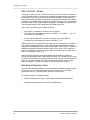
The User Interface: Display, Functions, Pages, and
Parameters
The key to the S4 Plus user interface is the combination of the Display and four Quad
Knobs/Buttons [1] – [4] located toward the right of the front panel. The Display
constantly informs you of the S4 Plus’s status.
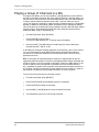
About the Display
Editing Status
MIDI Channel Cursor
MIDI Monitor/Selection Strip
MIDI
CHAN
MIX
PRESET
EDITED
Current Mix, Program and Effect Strip
Quad Knob/Button Label Strip
Mix/Program/Effect/Parameter Name Strip
1 2 3 4 5 6 7 8 9 10 11 12 13 14 15 16
PROG
EFFECT
PRESET
EDITED
PRESET
EDITED
EDITING: MIX PROGRAM SOUND 1 2 3 4 EFFECT CLIP
PROGRAM – ASSIGN – VOICE
LEVEL
EFFECT–LEVEL
PITCH FILTER AMP
RANGE
MOD EFFECT NAME
PLFO
FLFO
ALFO
PENV FENV AENV
TRACK
CONFIG
REVERB
DELAY
MIX
MISC.
GLOBAL
PAGE: 1 2 3 4 5 6 7 8 9 10 11 12 13 14 15 16 COMPARE
Page Number Strip
Function List
Function Cursor
Page Cursor
Compare indicator
Global indicator
Quad Knob bar-graph meters
Quad Knob Cursor
Clip indicator
Note: This illustration shows all display flags turned on at once. Actual displays show
only some of these at any time.
The display has eight main sections:
•
MIDI monitor and selection strip. Selects different MIDI channels for the
programs in Mix Play Mode (a thick underline indicates the selected channel),
monitors keyboard and incoming MIDI activity (thick lines above active channel
numbers indicates activity either from the keyboard or MIDI In), and chooses the
basic MIDI channel in Program Play Mode.
•
Current Mix, Program and Effect strip. Shows the currently selected Mix
and/or Program and its associated Effect.
•
Editing Status. Indicates what you are editing (either Mix Edit, Program Edit, or
Effects Edit), after pressing [SELECT]. “1 2 3 4” indicates which Sound (1–4) is
selected for editing when in Program Edit mode; or, which effect send (1–4) is
selected for editing when in Effects Edit mode. Press [EDIT 1] to cycle through
the four Sounds/sends. When Edit 4 mode is selected (press [EDIT 4]), all four
numbers appear, to indicate that all four Sounds are available for simultaneous
editing (Edit 4 mode is available in Program Edit mode only).
•
Functions list. Displays the various editing functions available in a particular
editing mode. Use the FUNCTION [¨] and [Æ] buttons to select a function, as
indicated by the small line (cursor) underneath one of the words in the list. When
a function is chosen, the page number strip and right-hand side of the display will
show values related to that function. Only the functions used by the current edit
mode will be displayed and selectable. Functions can also be selected from the
DIRECT SELECT buttons (see page 31).
Page number strip. Some functions have too many options to fit on a single
screen. These functions use multiple screens, with each screen considered a
page. This strip shows which page is selected by underlining the page number.
The PAGE [¨] and [Æ] buttons allow you to select a page.
•
26
S4 Plus Reference Manual
Overview: Chapter 4
•
Name strip. When in Mix Play Mode, the name of the currently selected Mix will
appear here. Likewise, when in Program Play Mode, the name of the currently
selected Program will appear here. In any Edit mode or Store mode, the name of
the currently selected parameter will appear here indicating it is selected for
editing using the VALUE [¨] and [Æ] buttons.
•
Quad Knob/Button Label strip. This line is used to show the labels of the bar
graph meters, which determine the functions of the four Quad Knobs and
Buttons. These labels change depending on which function and page is currently
selected. The labels are abbreviations of the parameters; the complete name
(and value) of a selected parameter will appear in the Name strip.
•
Quad Knob bar graph meters. When a Quad Knob controls a function’s
parameter, an associated bar graph appears which reflects the Knob’s setting.
Note: Not all four Quad Knobs are active in all pages. If a single line appears
somewhere in the bargraph area, it indicates its corresponding Quad Knob is
active.
MIDI Buttons
The MIDI [¨] and [Æ] buttons serve two purposes. In Program Play Mode, they select the
basic MIDI channel the S4 Plus will receive and transmit MIDI messages on. In Mix Play
Mode, they are used to select one of the 16 Channels for viewing and editing.
For more information on MIDI and its uses, see Chapters 8 and 9, and Appendix B.
Quad Knob Editing
The Quad Knobs have two editing modes: Immediate and Pass-thru. When using the
Quad Knobs to adjust parameter values, you may prefer using one mode over the
other. When set to Immediate, parameter values jump immediately to the Quad
Knob’s exact position the moment it is moved. When set to Pass-thru, the Quad Knob
must be turned beyond the parameter’s current setting before it becomes “live” and
begins adjusting the parameter’s value.
The editing mode is set in Global Edit mode, Page 2, using Quad Knob [3]. For more
information about selecting the Quad Knobs’ editing mode, see Chapter 8.
S4 Plus Reference Manual
27
Chapter 4: Overview
Parameter Editing
All parameter editing involves the same general procedure, with minor variations:
¿ Select the type of parameters you want to edit with the corresponding button:
[MIX ], [PROGRAM], or [GLOBAL].
Mix parameters edit a Mix. Program parameters edit a Program. Effects
parameters can be edited from within a Mix or a Program (see below). Global
parameters edit general characteristics that affect the entire instrument.
¡
Select an Edit Mode with the [SELECT] button.
Example: If you pressed [PROGRAM], the [SELECT] button switches between
two groups of functions—one for editing the Program’s Sound layers(Program
Edit Mode), and the other for editing the associated Effect (Effects Edit Mode). If
you’re editing a Mix, the [SELECT] button switches between three groups of
functions—one for editing the Mix’s parameters (Mix Edit Mode), one for editing
the Programs in the Mix (Program Edit Mode), and the last for editing the
associated Effect (Effects Edit Mode) .
¬ Use the FUNCTION [¨] and [Æ] buttons to select a function (level, pitch, etc.).
Press FUNCTION [Æ] to advance through the list, and FUNCTION [¨] to move
backwards. The selected function will be underlined in the display. Press both
FUNCTION [¨] and [Æ] simultaneously to get back to the first function in the list.
÷ If a function has multiple pages, select the appropriate page by using the PAGE
[¨] and [Æ] buttons.
The LCD’s page number strip shows the number of pages in a function; an
underline shows the currently selected page (e.g., if the display shows “1 2 3” then
page two is selected).
Press the PAGE [Æ] button to select the next higher-numbered page, and PAGE
[¨] to select the next lower-numbered page. Press both PAGE [¨] and [Æ]
simultaneously to get back to the first page of the selected function.
ƒ Select a parameter on the page for editing.
There can be up to four editable parameters on a page. The right side of the
display shows these parameters with both text and bar graph meters to give
instant visual feedback concerning a parameter’s value. Each of the four columns
has an associated Quad Knob and Button: the leftmost column monitors Quad
Knob/Button[1], the second from left column monitors Quad Knob/Button [2] , etc.
Turning a Quad Knob or pressing its Button selects the associated parameter for
editing. The currently selected parameter is indicated by a thick line at the
bottom of one of the four bar graph meters.
ª
Change the parameter value.
You can edit the value either by turning the associated Quad Knob (for large
value changes) or pressing the VALUE [¨] and [Æ] buttons (for smaller changes).
Each bar graph indicates a parameter’s approximate value—increasing a value raises
the column height. With bipolar values that can go positive or negative, turning a knob
clockwise increases the column height upward from the midpoint, and turning a knob
counterclockwise increases the column height downward (more negative value) from
the midpoint.
Always refer to the parameter name strip in the display above the bargraphs for the
current parameter label and value.
28
S4 Plus Reference Manual
Overview: Chapter 4
Editing Program Parameters
Here is an example of how to use the S4 Plus’s editing features to change Program
parameters. Feel free to make changes and twist dials; these will not be made
permanent unless you store the Program (described later).
¿ Press the [PROGRAM] button.
This selects Program Play Mode.
¡
Select a Program using the methods described on page 14.
The currently selected Program will appear in the upper right of the display.
¬ Press the [SELECT] button.
Pressing this button toggles between Program Edit mode and Effects Edit mode.
The display’s editing status line will indicate either “Editing: Program” or “Editing:
Effect.” To change edit status, press the [SELECT] button again. For now, select
“Editing: Program.”
÷ Select the desired function by using the FUNCTION [¨] and [Æ] buttons to step
through the various Function in the display (Assign Voice, Level, Effect Level,
Pitch, Filter, Amp, etc.). Alternatively, you can use the DIRECT SELECT buttons
(located on the far left of the front panel) to directly select a Function.
Pressing FUNCTION [Æ] advances to the next function, and FUNCTION [¨]
returns to the previous function. As you select the different edit Functions, the
page number strip shows how many pages exist for that function, and the right
part of the display will show the parameters on the current page.
ƒ Some functions have more parameters than will fit on a single display page, and
therefore will have multiple pages, as indicated in the lower left corner of the
display. To select a page within a particular edit function, use the PAGE [¨] and
[Æ] buttons.
Press the PAGE [Æ] button to advance to the next higher-numbered page or
PAGE [¨] to return to the next lower-numbered page.
ª
To adjust a parameter on a page, either:
•
Turn the associated Quad Knob [1] – [4].
•
Press the associated Quad Button [1] – [4] to select a parameter in the
display, then adjust its setting with the VALUE [¨] and [Æ] buttons.
S4 Plus Reference Manual
29
Chapter 4: Overview
Edit 4 and Edit 1 Modes
A Program is made up of four sounds. Sometimes, you need to edit four variables of
a single Program sound (for example, the attack/decay/sustain/release parameters of
an envelope). Other times, you may want to edit one variable in all four layers (for
example, the attack parameter of each layer). These two different methods of editing
a Program are available under the [EDIT 1] and [EDIT 4] buttons. The only difference
between the two modes is what variables will appear in the display at the same time.
You can switch between Edit 1 Mode and Edit 4 Mode at any time.
Note: There is no Edit 4 mode for Mixes or Effects.
¿ Press [EDIT 1] repeatedly to select a sound for editing.
The status line in the display will indicate ”SOUND 1,” or “SOUND
you continue to press [EDIT 1].
¡
2,” etc., as
To view and edit parameters for all four sounds at once, press [EDIT 4].
The status line in the display will indicate “SOUND 1 2 3 4.”
In Edit 4 mode, the four Quad Knobs represents the four sound layers of a Program.
The currently selected parameter’s name will appear at the top right of the display,
while above each bargraph are the words “SND1 SND2 SND3 SND4.” If a sound is
disabled, the display will show the sound’s name in lower case (“snd1” means that
sound 1 is disabled). If a sound is in Drum mode, the sound’s name will read “drmX,”
where X is the sound number (1–4).
Notice that the assignments of the Quad Knobs and the number of pages in a
function change between Edit 1 Mode and Edit 4 Mode. For example, in Edit 1 mode
the LEVEL function has only one page which shows the Volume, Pan and Output of a
single sound. In Edit 4 Mode, the Level function has three pages: all four sound
volumes are page 1, all pans are on page 2, and all outputs are on page 3.
Resetting a Parameter Value
It’s often convenient while editing to return a parameter to its default setting (usually,
but not always, 0). This normally involves turning a Quad Knob or repeatedly
pressing the VALUE [¨] and [Æ] buttons, but here’s a quicker way:
To reset a parameter to its default setting:
¿ Select the parameter you wish to reset using the methods described earlier.
¡
30
Simultaneously press both the VALUE [¨] and [Æ] buttons.
S4 Plus Reference Manual
Overview: Chapter 4
Comparing Edited and Stored Versions
When you edit a Program or Mix, you are actually editing a copy which is in a
temporary edit buffer. Therefore, to retain the results of your edit, you must save it to
a particular memory location (see the next section on Storing). If you change memory
locations before saving, the buffer will be replaced and your edits lost.
Because the original Program/Mix remains undisturbed, you can compare the edited
version to the original by using the Compare function. You can only select Compare
mode when either Mix Edit, Program Edit or Effects Edit is selected, and the word
“EDITED” appears in the display below either “MIX,” “PROG” or “EFFECT.”
¿ Press [COMPARE ].
The word “COMPARE” will appear in the display, while the word “EDITED” will
disappear.
¡
J
Press [COMPARE] again to exit Compare mode and return to the edited version.
The word “COMPARE” will disappear from the display, and the word “EDITED”
will reappear. Pressing [MIX], [PROGRAM], [GLOBAL], [STORE] or the
MIX/PROGRAM SELECT [1]—[0] buttons will also exit Compare mode.
While Compare mode is selected, you can move around to view the various
parameters, but you will not be able to edit anything. This is because you are seeing
what is in memory, not what is in the edit buffer.
Preset Memory and User Memory
The S4 Plus has two types of memory banks for Mixes and Programs: Preset and
User. The Preset banks, of which there are four, are stored in ROM (Read Only
Memory), and therefore cannot be altered. However, the User bank, of which there is
1, is stored in RAM (Random Access Memory). Anytime you want to keep an edited
version of a Mix or Program, you will store it into the User bank or onto a RAM Card.
If you want to permanently change a Mix or Program that is in the Preset bank, you
can store the edited version into the User bank (in either the same number location or
a different number location). However, this requires that you “store over,” losing
whatever was previously in that location. If you don’t want to lose any of the sounds
in the User bank, you should back-up the entire bank to either an external SRAM or
FlashRAM PCMCIA card, or (via MIDI System Exclusive) into a data storage device
like the Alesis DataDisk or a MIDI sequencer. See Chapter 9 for more information on
external storage operations.
S4 Plus Reference Manual
31
Chapter 4: Overview
Storing
The [ STORE] button selects Store mode. Store mode has 6 pages which you can
scroll through by using the PAGE [¨] and [Æ] buttons. Each page in Store mode
provides a different type of storage, copy or data transfer function. When storing
edited Mixes, or Programs into the User Bank or a RAM Card Bank, you will use the
first page of Store mode (for more information about the other pages of Store mode,
see Chapter 9). If you press [STORE] while in Mix Play Mode, the display will look
like this:
MIDI
CHAN
1 2 3 4 5 6 7 8 9 10 11 12 13 14 15 16
MIX
PRESET
EDITED
PROG
PRESET
EFFECT
PRESET
PAGE: 1 2 3 4 5 6
Once you have edited a Mix, a Program, or an Effect, the word “EDITED” will appear
in the display. If this word appears next to the Mix Number, the Mix has been edited;
if it appears next to the Program Number, the Program has been edited; if it appears
next to the Effect Number, the Effect has been edited.
Each edit mode type requires its own store operation. For example, if while making a
new Mix you also make changes within one of the Programs (such as lowering the
filter level), you must use the Store command separately (from Mix Edit, and
Program Edit or Effect Edit) in order to save your work. Note: When using the Store
command from Effect Edit Mode, the associated Program is stored. This is because
Effects are stored within their respective Programs.
If you select a different Mix while in Mix Edit mode, or a different Program in Program
Edit mode, you will lose all changes you have made, unless you perform a store first.
J
You can only store Mixes, Programs, and Effects into their respective User banks.
The Preset banks are permanently stored in ROM and cannot be saved over.
Store a Program
¿ While in either Program Play Mode or Program Edit mode, after making your
edits press the [STORE] button.
¡
J
Select the memory Bank and location to which you want to store the Program
using Quad Knobs [1] and [2]. respectively.
If no RAM Card is inserted, you will only be able to select the User Bank.
Don’t use the DIRECT SELECT [1]—[0] buttons. Doing so will result in recalling a
different Program and you will lose your changes.
¬ Press [STORE] again to complete the operation.
Or, Press any other button to cancel out of the Store operation without storing.
32
S4 Plus Reference Manual
Overview: Chapter 4
Copying Effects Between Programs
Follow the steps below to copy the Effects from one Program to another Program in
the User Bank.
¿ Press [PROGRAM] to select Program Play Mode.
¡
Use the VALUE [¨] and [Æ] buttons to select the Program Number that uses the
Effects you want to copy. If necessary, use the FUNCTION [¨] and [Æ] buttons to
select a different Bank.
¬ Press [STORE].
÷ Press PAGE [Æ] once to advance to Page 2.
The top right section of the display will read “ COPY TO SOUND 1”.
ƒ Turn Quad Knob [1] clockwise until the display reads “COPY FROM EFFECT”.
This selects the Effects of the currently selected Program as the source of what
is to be copied.
ª
Turn Quad Knob [2] to select the Program Number in the User Bank you wish to
copy the Effects to (000–127).
D Press [STORE] to complete the copy function.
Store an Effect
If you have edited a Program’s Effect and would like to store it without storing the
changes you’ve made to the Program’s parameters, you can use the Copy Effect
function to store only the Effects edits to the currently selected Program. When you
recall this Program, it will have the new Effects settings you saved it with, but will
retain its previously stored Program parameter settings.
Store a Mix
¿ While in either Mix Play Mode or Mix Edit mode, after making your edits press the
[STORE] button.
¡
J
Select the memory Bank and location to which you want to store the Mix using
Quad Knob [1] and [2]. respectively.
If no RAM Card is inserted, you will only be able to select the User Bank.
Do not use the DIRECT SELECT [1]—[0] buttons. Doing so will result in recalling a
different Mix and you will lose your changes.
¬ Press [STORE] again to complete the operation.
J
Storing a Mix only stores the Mix parameters, not the individual Programs or Effect
Patch used in the Mix. If you have edited any of the Programs in the Mix or the
Effects Patch, you must store them separately.
S4 Plus Reference Manual
33
Chapter 4: Overview
To Audition Programs Before Storing
To look for available memory locations to permanently store your Program to, you
can move between Program Mode and Mix Mode without losing your changes. This
is because Program Mode has a Program edit buffer, and Mix Mode has its own Mix
edit buffer along with 16 Program edit buffers. These buffers are retained when
moving between Program Mode and Mix Mode, thus making it easy to search for a
suitable location to store your newly created Program. Example: While in Program
Edit mode, go to Mix Mode and scroll through the Program list on one of the
Channels; while editing a Program from Mix Mode, go to Program Mode to scroll
through the Program list.
The way to tell the difference between a program edited in Program Mode and one
edited from Mix Mode is simple: in Program Mode, the MIX number does not appear
in the display.
J
You will lose your changes if you remain in the same mode and recall a different
Mix/Program by pressing the MIX/PROGRAM SELECT [1]—[0] buttons.
To audition Programs before overwriting them with STORE
…when editing a Program in Program Mode:
¿ While in Program Edit mode, press [MIX].
This selects Mix Play Mode, retaining your edits to the Program in an edit buffer.
¡
Using the BANK and DIRECT SELECT buttons, select Mix 99 in Preset Bank 1.
¬ Press [SELECT] to enter Mix Edit Mode, and press both MIDI [¨] and [Æ] buttons
simultaneously to select Channel 1.
÷ Press both FUNCTION [¨] and [Æ] buttons simultaneously so the words
“PROGRAM – ASSIGN” are underlined.
ƒ Turn Quad Knob [1] to the left so that the word “USER” appears in the top part of
the display, just before the Program name. If a RAM card is inserted, use Quad
Knob [1] to select a Card Bank.
ª
Turn Quad Knob [2] to scroll through the Programs until you find one you wish to
overwrite with the new edited Program. Take a note of the number.
D Press [PROGRAM] to enter Program Play Mode.
This recalls the edit buffer in Program Mode, which is your edited Program.
« Press [STORE].
The top right of the display will read “STORE PRG UsrXXX?” where XXX is a
User Program number from 000—127.
» Use Quad Knob [2] to enter the Program number you noted in step 6. If
necessary, use Quad Knob [1] to select a Card Bank.
… Press [STORE] again.
The Program is now stored.
34
S4 Plus Reference Manual
Overview: Chapter 4
To audition Programs before overwriting them with STORE
…when editing a Program in Mix Edit Mode:
¿ While in Mix Program Edit mode, press [PROGRAM].
This selects Program Play Mode, retaining your edits to the Program in Mix Edit.
¡
Press the BANK [¨] button until the word “USER” appears in the top part of the
display, just before the Program name. If a RAM card is inserted, use the BANK
buttons to select a Card Bank.
¬ Use the VALUE [Æ] and [¨] buttons to scroll through the Programs until you find
one you wish to overwrite with the new edited Program. Take note of the number.
÷ Press [MIX].
This recalls the edit buffer in Mix Mode, which contains your edited Program.
ƒ Press [SELECT] twice, until “EDITING: PROGRAM” appears under the MIX
number in the display.
ª
Press [STORE].
The top line of the display will read “STORE PRG UsrXXX?” where XXX is a
User Program number from 000—127.
D Use Quad Knob [2] to select the Program number you noted in step 3. If
necessary, use Quad Knob [1] to select a Card Bank.
« Press [STORE] again.
The Program is now stored.
At this point your edited Program is stored, however the Mix you were auditioning
before storing the Program still has the old Program number assigned (if the edited
Program was saved to a different Program number location). Therefore, you need to
re-select the new Program number from within Mix Edit mode.
» Press [MIX], then [SELECT] to access Mix Edit mode.
… Use the MIDI [¨] and [Æ] buttons to select the MIDI channel you want, and use
the VALUE [Æ] and [¨] buttons or Quad Knob [2] to select the Program number. If
necessary, use Quad Knob [1] to select the Bank.
S4 Plus Reference Manual
35
Chapter 4: Overview
36
S4 Plus Reference Manual
Editing Mixes: Chapter 5
CHAPTER 5
EDITING MIXES
What is a Mix?
Mix Mode is one of the most powerful features of the S4 Plus. While in Program
Mode you can play only one Program at a time, in Mix Mode you can play up to 16
Programs at once, either from the keyboard (as layers or splits) or from an external
sequencer (via 16 MIDI channels) or a combination of both.
With Mix Mode, you can do the following:
•
Combine (“stack” or “layer”) different Programs so they can be played
simultaneously from the keyboard. For example, stack a piano on top of a brass
patch and a string patch, adjusting the volume of each for a desirable mix. (Note
that the stacking of Programs in Mix Play Mode is in addition to any sounds that
may be stacked in the four sound layers of each Program.)
•
Split the keyboard into different zones--for example, the classic bass guitar on
the left-hand side of the keyboard and synth or piano on the right. You can split
the keyboard into as many as 16 zones.
•
Transmit on several different MIDI channels simultaneously.
•
Receive up to 16 MIDI channels from an external sequencer, with each channel
representing a different instrument--piano on Ch. 1, bass on Ch. 2, drums on Ch.
10, trumpet on Ch. 16. Mix Play Mode is the multitimbral mode of the S4 Plus.
•
Set the relative level, panning, and effect send of each MIDI channel.
Mix Edit Mode
To edit a Mix you must select Mix Edit mode. Press [SELECT] from Mix Play Mode.
"Editing: Mix" should appear in the edit status section of the display:
MIDI
CHAN
1 2 3 4 5 6 7 8 9 10 11 12 13 14 15 16
MIX
PRESET
PROG
PRESET
EDITING:
MIX
PROGRAM – ASSIGN
PITCH
RANGE
EFFECT
PRESET
LEVEL
EFFECT–LEVEL
EFFECT NAME
PAGE: 1
Note: This illustration shows a Mix with all 16 MIDI channels enabled. If a channel is
not enabled, its number will not show in the display unless the MIDI cursor is under
the number.
Editing a Mix begins with using the MIDI [¨] and [Æ] buttons to select the MIDI
channel you want, and assigning a Program number for the channels you want to
use. Each channel may be enabled or disabled, without changing any of its
parameter settings. When a channel is disabled, its number will not appear in the
upper left display, except when it is selected for editing. You can set levels, effect
levels and bus assignments, pitch transposition, keyboard ranges (if making a split or
layer), and MIDI parameters for each individual channel. Each function is selected
S4 Plus Reference Manual
37
Chapter 5: Editing Mixes
using the FUNCTION [¨] and [Æ] buttons and (if necessary) the PAGE [¨] and [Æ]
buttons. A Mix also uses the Effect Patch associated with one of its 16 Programs.
Here is a simplified diagram of the signal path in Mix mode.
Understanding the Edit Buffers
In Mix mode, there are 16 Program edit buffers (one for each channel), plus another
buffer for the Mix parameters (Level, Pitch, Range, etc.), and yet another buffer for
the Effects Processor. When you select a Mix from memory, it is copied into the Mix
Edit buffer, the 16 Programs of that Mix are copied into the 16 edit buffers, and the
Effect from one of the 16 Programs is copied into the Effects buffer. If you make
changes to the Mix, they are only temporarily kept in the edit buffer until a new Mix is
selected from memory. Therefore, you MUST store your edited Mix if you want to
keep it.
If in the course of making a Mix, you enter Program Edit mode (by pressing
[SELECT]) and edit one or more Programs in the Mix, the edits you make are entered
into a separate buffer for each Program in the Mix. Note, however, that you DO have
to STORE each edited Program in the User bank (in the same or different Program
number location) before selecting a different Mix, or your changes will be lost. The
same goes for editing the Effects, which will be stored with its associated Program. If
you select another Mix before storing, your changes will be lost.
38
S4 Plus Reference Manual
Editing Mixes: Chapter 5
Program Assign for each MIDI Channel
The first function of Mix Edit is Program Assign.
Program Bank (User, Preset 1–4, Card)
This determines which Bank the selected Program is located in for the selected MIDI
channel. There are five Banks available in the S4 Plus. If you insert a QuadraCard
Sound Card, you can have even more Banks.
Program Number (000 to 127)
This determines the Program Number (000—127) for the selected MIDI channel.
Enable (On or Off)
This determines whether the Program on the selected channel is enabled or disabled.
When disabled, no sound will be generated by the S4 Plus. The Channel number in
the display for a disabled channel will not appear except when selected for editing.
J
Even if a channel is enabled here, it will not play unless the proper settings in the
RANGE function (MIDI IN and/or KEYBOARD On/Off and LOW/HIGH) are made.
Level Setting for Each Program
The second function of Mix Edit is Level .
Level (00 to 99)
This sets the overall volume for a sound. Higher numbers give higher levels.
Pan (<3 to 3>, or PG )
This determines the pan position of the selected channel. When set to PG, the
panning setting will be that of the Program assigned to the selected channel.
However, you can override this setting by selecting a different value, thereby
assigning the channel’s panning between the left and right outputs of either the MAIN
or AUX outputs (depending on the Output assignment--see below).
Output (MAIN, AUX, OFF, or PROG)
This determines the audio output assignment for the selected channel. When set to
PROG, the channel will use the Output assignment of the Program. However, you
can override this assignment by setting this parameter to something different.
Selecting MAIN or AUX will assign the channel to the MAIN or AUX audio outputs.
When set to OFF, the channel will not be sent to either set of outputs (but can still
feed an effect bus).
S4 Plus Reference Manual
39
Chapter 5: Editing Mixes
Pitch
The Pitch function lets you transpose a channel’s Program in either semitone or
octave increments. By using both parameters together, you have a total transposition
range of ±3 octaves.
Octave (-2 to +2 octaves)
This transposes the Program’s pitch in octave (12 semitone) steps from -2
(transposed down 2 octaves) to +2 (transposed up two octaves).
Semitone (-12 to +12 semitones)
This transposes the Program’s pitch in semitone steps, from -12 (transposed down
one octave) to +12 (transposed up one octave).
Setting the Range and MIDI Switches
Each sound can be restricted to a specific range of the keyboard. This is ideal for
creating splits (e.g., bass in the lower octave and a half, piano in the middle three
octaves, and strings in the upper octave). When you start to setup a MIX, it may be
confusing if many of the channels have their Keyboard parameter turned off. In order
to hear anything on a particular channel, enable Keyboard control and set the Range
so that the low note and high note values are set beyond where you want to play.
Look at the MIDI MONITOR section of the display. A thick line will appear above any
active MIDI channels as you play notes or send notes to the S4 Plus from a
sequencer on those channels.
Range (Page 1)
Lower Limit (MIDI note 000 to 127/ C-2 to G8)
Specifies the lowest note of the sound’s keyboard range. You can set the lower limit
by holding Quad Switch [1] and tapping the key on the keyboard you want to set as
the lowest note in the range.
High Limit (MIDI note 000 to 127/ C-2 to G8)
Specifies the highest note of the sound’s keyboard range. You can set the high limit
by holding Quad Switch [2] and tapping the key on the keyboard you want to set as
the highest note in the range.
J
If the lower limit is set above the high limit, there will be no sound from this program
layer.
Typical 5-octave Keyboard Range
0
12
24
36
48
60
72
84
96
108
120 127
C-2
C-1
C0
C1
C2
C3
C4
C5
C6
C7
C8 G8
Program Sound Range
40
S4 Plus Reference Manual
Editing Mixes: Chapter 5
Range (Page 2)
MIDI In (On or Off)
This determines whether or not the selected channel will respond to incoming MIDI
messages.
MIDI Out (On or Off)
In the QuadraSynth Plus Piano, this determines whether or not the selected channel
will transmit MIDI messages. However, in the S4 Plus, this parameter has no effect (it
will be shown in lowercase letters in the display).
Group (On or Off)
This determines whether or not the selected channel will respond to MIDI information
that is received on the Group Mix Channel. The Group Mix Channel is set globally for
all Mixes, and can be found in Global Edit Mode, Page 2, Quad Knob [2]. For more
information, see page 44.
Range (Page 3)
The following four parameters determine whether or not specific types of MIDI
information will be received or transmitted, and are set separately for each Channel in
the Mix. These, however, are dependent on how the individual Channels have their
Range Page 2 parameters set (described above).
Pitch-bend and Modulation Wheels (On or Off)
This determines whether or not the selected channel will transmit and receive pitchbend and modulation (controller 1) MIDI information.
Aftertouch (On or Off)
This determines whether or not the selected channel will transmit and receive
aftertouch MIDI information.
Sustain Pedals (On or Off)
This determines whether or not the selected channel will transmit and receive sustain
pedal (controller 64) MIDI information.
Controllers (On or Off)
This determines whether or not the selected channel will receive MIDI controller
information which the Controllers A–D and Pedals 1 & 2 are assigned to (these are
assigned to MIDI controllers in Global Mode, Page 3 and 5).
S4 Plus Reference Manual
41
Chapter 5: Editing Mixes
Effects in Mix Play Mode
In Mix Play Mode, you can have only one Effect Patch active per Mix, which will be
the Effects Patch associated with one of the Programs used in the Mix. However, the
Mix’s Effect Patch still has 4 independent effect buses, and you can set the effect
send level and routing from each Program layer to the effects processor.
The S4 Plus offers you a choice of what parameters to use for effects:
•
The Effect Channel determines which one of the Programs in the Mix you want
to use the Effects Patch from. For example, if the Effect Channel is set to 10,
you will use whatever effect is used by the program on MIDI channel 10.
•
The effect levels and bus assignments of the Program on each Channel can
be set directly by the Mix, or you can use the same levels and buses that were
stored in each Program.
Effect Level
The Effect function is where each channel may be given its own Effect Level and
Effect Bus assignment.
Effect Level (00 to 99, or PROG)
This determines the amount of signal from the selected channel that will be sent to
the effects, using one of the four effects buses as determined by Quad Knob [2].
Effect Bus (1, 2, 3, 4, or PROG)
Quad Knob [2] determines which effect bus the selected channel will be routed to.
When set to PROG, the effect bus assignment will be that stored by the channel’s
Program. 1, 2, 3 or 4 overrides the Program’s bus assignment, sending all sound
layers of the Program to the chosen bus.
Effect
The Effect function is where you select what Effect Patch will be used by the Mix, by
linking the Effect to one of the Programs in the Mix.
FX Channel (1 to 16)
The Effect Channel determines which channel’s Program’s Effect Patch will be used
for the entire Mix. In other words, when the Effect Channel is set to 3, the Mix will use
the Effect Patch used by the Program assigned to channel 3.
FX MIDI (On or Off)
This determines whether the Effects settings will change along with its Program, if a
MIDI program change is received on the Effect Channel. If on, and a MIDI program
change is received, a new Program will be recalled along with its associated Effect
Patch. This, however, can change the way the other Programs in the Mix sound,
since they all share the same Effects Patch. If you want to recall Programs via MIDI
program changes, but want to continue using the same Effects Patch, leave this
parameter turned off.
If a program change is received on the Effects Channel and the FX-MIDI parameter is
off, the Program will change to the new number (as determined by the program
change number that was received) and the Effects Patch will also change to a new
number. However, the previous Effects Program will be copied into the Mix’s Effects
buffer and the word “EDITED” will appear next to the Effects Patch number. This
42
S4 Plus Reference Manual
Editing Mixes: Chapter 5
indicates that, although the Effects Patch number coincides with the Program number
on the Effects Channel, the Mix is still using the Effects Program connected to the
original Program on the Effects Channel that is stored in the Mix. If you store the Mix,
the newly selected Program on the Effects Channel will be stored with it. The next
time this Mix is recalled the new Program on the Effects Channel will be recalled
along with its Effects (which will be different, in most cases, from the Effects originally
used with this Mix). If this occurs, and you wish to keep the new Program in the Mix,
you could copy the Effects from the old Program into the new Program (see the Store
Mode section, later in this chapter). Or, you could adjust the Effects Send level and
Effects Bus parameter for the remaining Channels so that their associated Programs
sound good with the new Effects. Or, you could modify the new Program’s Effects.
Naming a Mix
The Name function allows you to change the name of the Mix. The Mix name can be
up to 10 characters long. Use the PAGE [¨] and [Æ] buttons to position the cursor.
Quad Knob [1] selects the character. Here is a chart of available characters:
4
H
¥
p
!
5
I
]
q
"
6
J
^
r
#
7
K
_
s
$
8
L
`
t
%
9
M
a
u
&
:
N
b
v
’
;
O
c
w
(
<
P
d
x
)
=
Q
e
y
*
>
R
f
z
+
?
S
g
{
,
@
T
h
|
A
U
i
}
.
B
V
j
Æ
/
C
W
k
¨
0
D
X
l
1
E
Y
m
2
F
Z
n
3
G
[
o
Polyphony in Mix Play Mode
The S4 Plus has 64-note polyphony. In Mix Play Mode, if you have all 16 MIDI
channels assigned to the same keyboard range, and each channel's Program has
only one active Program Sound, you’ll have 4-note polyphony as you play the
keyboard (but a really thick layer...). This is extreme, of course, but should tell you
what you can expect when you really pile on the layers from the keyboard.
S4 Plus Reference Manual
43
Chapter 5: Editing Mixes
Playing a Group of Channels in a Mix
In Program Play Mode, you can use the MIDI [¨] and [Æ] buttons to set the MIDI IN
channel for the whole instrument. But when using the S4 Plus in Mix Play Mode, you
may need to be able to transmit on several MIDI channels from your MIDI keyboard,
in order to play the different channels within a Mix. However, there is a way to
“group” any number of channels in a Mix to all play simultaneously from a single MIDI
channel (in addition to responding to MIDI information on their individual channels).
This can be done by combining the Group parameter (found in Mix Edit Mode, Range
Function, Page 2, Quad Knob [4]) and the Mix Group Channel function (found in
Global Edit Mode, Page 2, Quad Knob [2]).
¿ From Mix Play Mode, press [GLOBAL].
¡
Press PAGE [Æ] to get to Page 2.
You will see "MIX GROUP CH: " in the top right of the display.
¬ Use the VALUE [¨] and [Æ] buttons or Quad Knob [2] to set the Mix Group
Channel between 1 and 16, or Off.
1–16. When the Group Mix Channel parameter is set between 1 and 16, the number
it is set to determines the single MIDI channel which, when MIDI information is
received on it, will play the channels in the selected Mix which have their Group
parameter turned on.
OFF. In this mode, the individual channels used by the selected Mix will only be
triggered by MIDI information received on its designated MIDI channel ( Example: the
sound on channel 1 will only respond to information received on MIDI channel 1, the
sound on channel 2 will only respond to information received on MIDI channel 2,
etc.), regardless of whether each channel’s Group parameter has been turned on or
off. However, the MIDI In parameter for each channel must be turned on in order for
that channel to respond to incoming MIDI information on its own channel.
To turn on the Group function for a channel in a Mix:
¿ From Mix Play Mode, press [SELECT].
¡
Press FUNCTION [Æ] until the Range function is underlined.
¬ Press PAGE [Æ] until Page 2 is selected.
÷ Use the MIDI [¨] and [Æ] buttons to select a channel in the Mix.
ƒ Turn Quad Knob [4] to turn on the Group parameter.
44
S4 Plus Reference Manual
Editing Programs: Chapter 6
CHAPTER 6
EDITING PROGRAMS
Overview
Synthesizer programming is the art and science of shaping sounds in a particular way
by altering the parameters of various modules. Like music itself, learning synth
programming is an ongoing process. Although this manual presents information
about synthesizer programming, no manual can offer a complete course in
programming (at least for a price that customers would be willing to pay!).
If you’re new to synthesizer programming, the best way to learn is to adjust different
parameters as you play to discover how different parameter values affect the sound.
Also, become familiar with the signal and modulation flow within the S4 Plus (as
shown in the various block diagrams included in this manual) so that you can
understand the many ways in which you can process a signal as it works its way from
oscillator to output.
The “Normalized” Synth Voice
The first synthesizers were comprised of various hardware modules, some of which
generated signals, and some of which processed those signals. These were
designed to be general-purpose devices since nobody was quite sure how they would
be applied; some engineers used them as signal processors, while keyboard players
treated them as musical instruments. Therefore, patch cords connected the inputs
and outputs of the various signal generating and processing modules (which is why
particular synth sounds were called patches). Changing a patch involved manually
repositioning patch cords and adjusting knobs and switches; recreating a patch
required writing down all the patch settings on paper so they could be duplicated
later. Even then, due to the imprecision of analog electronics, the patch might not
sound exactly the same.
Over the years, certain combinations of modules seemed to work better than others,
and since patch cords were troublesome to deal with, eventually these modules were
wired together in a "normalized" configuration. Synthesizers such as the MiniMoog,
Prophet-5, and others eliminated the need for patch cords by containing a normalized
collection of sound modules (including oscillators, filter, envelopes, LFOs, etc.).
The S4 Plus offers the best of both worlds. The most commonly-used, normalized
configurations are built-in to every program for ease of programming. In addition, the
QS Modulation Matrix gives back much of the flexibility of a modular synthesizer,
allowing you to map various modulation sources to multiple destinations for special
needs. If you’re a beginner, all of the normalized pathways are easy to find; as you
gain experience you can explore more advanced features.
How the S4 Generates Sound
The S4 Plus uses custom integrated circuits, developed by the Alesis engineering
team specifically for the S4 Plus. These resemble the types of chips used in
computers and other digital devices. In fact, you can think of the S4 Plus as a specialpurpose computer designed to generate and process audio. Although the user
S4 Plus Reference Manual
45
Chapter 6: Editing Programs
interface maintains the metaphor of “modules,” in fact all sounds are simply a set of
numbers reflecting how you’ve programmed the various sound parameters. For
example, when you change the filter cutoff frequency, you’re not actually messing
with a filter; you’re telling the computer to simulate the effect of messing with a filter.
Each "module" is represented by parameters that appear on one or more display
pages. The Quad Knobs and Buttons change these parameters. All "patching" is
done via software, so the only patch cords you need are those that go to your mixer
or amplifier.
You can take a "snapshot" of the S4 Plus’s parameters and save this in memory as a
program. The S4 Plus comes with 512 factory preset programs, and 128 user editable programs.
Program Sound Layers
The simplest method of programming is to take one voice, process it through the filter
and amp sections, and (if desired) add some effect to it. However, more elaborate
Programs usually consist of 2 to 4 layers, with each layer making its own distinct
contribution to the sound, for example:
•
An organ program with Program Sound 1 set to a sustained organ waveform, and
Program Sound 2 set to a percussion waveform with a fast decay.
•
A piano program with one layer tuned normally, and a second layer tuned an
octave higher.
•
A synthesizer program with one layer set to a sharp attack waveform, a second
layer set to an acoustic waveform, and a third layer with a slow-attack string
waveform.
This may remind you of Mix Play Mode, where playing the keyboard can sound up to
16 different Programs at once. There are many similarities. In Mix Play Mode, you
can make the same kind of layered Mix as you can with the four sounds of a
Program. But there are differences:
Use Program Layers:
•
If you want multiple sounds to respond to a single MIDI channel. For example, if
you need to play a layered synthesizer sound that was assembled in Mix Play
Mode instead of Program Play Mode, you must send 3 Note On messages from
your sequencer (one for each channel) for every note; a layered program would
need only one Note On message.
•
When layers of a Program are designed to be used together, and the individual
layers by themselves wouldn't be used alone (for example, the percussion layer
of the organ sound).
Use Mix Play Mode:
46
•
When you want to layer more than four voices. In Mix Play Mode, it is possible
(though not advisable) to stack all 64 voices onto a single key.
•
When each sound is likely to be used by itself by other setups. For example, if
you are programming three different keyboard splits, each of which uses the
same left-hand bass patch, it makes sense to use Mix Play Mode.
S4 Plus Reference Manual
Editing Programs: Chapter 6
•
When you want different sounds to respond to different MIDI channels.
S4 Plus Signal Flow
The Four Sounds of a Program
Each Program is made up of at least one to four sounds. A sound is made up of
several components including a voice (the original sound material) which passes
through a low-pass filter and an amplifier. The voice, filter and amp modules each
have direct modifiers (Pitch LFO, Filter LFO, Amp Envelope) which affect how each
will function in the Program. You can layer these sounds together, or divide them into
regions of the keyboard, or a combination of these things.
The following diagram illustrates the signal flow within each S4 Plus Program.
Sound 1
Pitch
LFO
Filter
LFO
Amp
LFO
Range
Voice
Filter
Amp
MIDI
Input
Main L
Pitch
Envelope
Filter
Envelope
Pan
Output
Amp
Envelope
Main R
Sends
1—4
Effects
Level
Effects
Buss
Assignable Modulation Sources
Aux L
Aux R
Effects
Processor
(reverb, delay,
chorus, etc.)
(velocity, aftertouch, modulation wheel, pitch bend, etc.)
Sound 2
Sound 3
Sound 4
Let’s look at each module’s function in detail.
S4 Plus Reference Manual
47
Chapter 6: Editing Programs
Voice
This digitally-based oscillator provides the actual raw sounds from the 24 megabyte
library of on-board samples. The oscillator's pitch can be tuned to a fixed frequency
or modulated. Modulation is the process of varying a parameter dynamically over
time; the oscillator pitch can be modulated by envelope, keyboard, pressure, pedal,
LFO, and other control sources (described later).
Note that the waveforms in the S4 Plus are different from those found in samplers or
many sample-playback units. Because the S4 Plus has its own filter module and
amplitude module for each voice, the pure waveforms are relatively bright--as bright
as the original instrument can be--and have a constant sustaining amplitude, like an
organ. So if you listen to a piano voice without setting the filter or amp to the correct
settings, it won't decay after it is hit, as you might expect. This gives you the freedom
to create the timbre and dynamics you want, instead of being chained to the
parameters of the original sample.
Lowpass Filter
A lowpass filter varies a signal's harmonic content by progressively increasing
attenuation above a specified cutoff frequency. The higher frequencies are filtered,
while the lower frequencies are allowed to “pass-thru.” When the cutoff frequency is
set high, the sound becomes brighter; when set low, the sound becomes bassier
since fewer harmonics are present.
Cutoff
Frequency
Frequency Response Curve
Filter
Amplitude
Frequency
00
99
The cutoff parameter changes the frequency at which the highfrequency response starts to roll off. Lower values give a lower
cutoff frequency. A value of 00 will cut all sound off.
Static (non-changing) filter settings can be useful, but varying the filter cutoff
dynamically over time often produces more interesting effects. Modulating with
velocity produces brighter sounds with louder dynamics, which produces a more
accurate acoustic instrument simulation. Modulating with an envelope can create a
pre-defined change in harmonic structure, such as having a brighter attack and
bassier decay.
Amp
48
S4 Plus Reference Manual
Editing Programs: Chapter 6
Each voice/filter combination is followed by an amplifier whose level can be controlled
by a variety of modulation sources. This allows for creating sounds with percussive or
slow attacks, particular types of decays, tremolo, etc.
Filter and amp settings can interact. If the filter cutoff is extremely low, then no signal
will get through, no matter how the amp is set. Similarly, setting the amp for a short
decay won’t let you hear any filtering set for a longer decay. This is because the
volume will reach zero before the filter decay finishes.
About Modulation
Modulation modifies some aspect of a sound over time. Since oscillators make static
sounds (unlike acoustic instruments, whose timbre and dynamics change—often
radically—over the duration of a note), modulation is the key to making rich and
expressive sounds. The vibrato of a flute, the expression pedal of an organ, a wahwah pedal on a guitar--all of these are examples of modulation. You're probably
familiar with the mod wheel of a synthesizer, that typically adds vibrato to a Program
as it is raised. But in synthesizer programming, modulation is used to control even
the basic characteristics of a voice: its attack, decay, and release times, for example.
Every box in the signal diagram on page 47 pointing towards the Voice, Filter, or Amp
boxes is a modulation source. The amount of modulation, the time it takes place, and
what controls (such as key velocity, footpedals, aftertouch, mod wheel etc.) affect it
are important parameters in every Program. The S4 Plus provides the modulation
flexibility of patch cord-based instruments, but with the convenience and ease of use
of digital technology.
With some parameters, the modulation amount can be positive or negative. A positive
control signal increases the value of the parameter being controlled. A negative
control signal decreases the value of the parameter being controlled. Setting
modulation to 00 turns off the modulation source. Example: Keyboard velocity can
either make a sound brighter the harder you play, or make it less bright, or have no
effect on the filter at all. You have the freedom to set modulation any way you want,
even in ways that are the opposite of what they would be on an acoustic instrument.
If a "baseline" setting exists for a parameter, modulation amounts add or subtract
values from the existing setting. However, modulation cannot force a value beyond its
maximum range. For example, if the amp is already at its minimum value (lowest
level), you could apply positive modulation to raise the level. But applying negative
modulation will not affect the amp level, since it's already at its lowest value and
cannot go any lower.
The S4 Plus lets you assign several modulation sources to one modulation “target”
parameter, which allows for interaction between two modulation signals. Example: If
the amp parameter responds to both the envelope generator and a pedal, the
parameter will follow the general envelope shape but will also be influenced by the
pedal.
S4 Plus Reference Manual
49
Chapter 6: Editing Programs
LFO (Low Frequency Oscillator)
The pitch, filter, and amp modules each have a dedicated LFO module for
modulation. The term LFO stands for low frequency oscillator, and comes from how
modulation was created in the early synth days (an oscillator set to a low frequency
could modulate some aspect of the sound; routing the LFO to the pitch, for example,
would create vibrato). The LFO creates a cyclic (periodic) modulation; this amount
can be constant and/or varied with a variety of modulation sources (mod wheel is one
of the most popular). Each LFO has a waveform shape and speed, along with other
controls.
Envelopes
Envelope generators provide a modulation signal that varies over time, from the time
you strike the key until after you let go. There are three independent envelope
generators (for pitch, filter, and amp) in each Program Sound. An envelope generator
has different effects on different modules. Example: The Amp Envelope creates level
changes. Amplitude that decays over time creates percussive effects (plucked
strings, drums, etc.). Amplitude that increases over time gives the effect of brass,
woodwind, and some bowed instruments.
Each envelope generator has the standard attack, decay, sustain, and release
parameters found on most synthesizers, along with delay, sustain decay, and
different triggering options.
DECAY
SUSTAIN LEVEL
L
E
V
E
L
RELEASE
DELAY
ATTACK
SUSTAIN DECAY
TIME
NOTE ON
NOTE OFF
About Signal Processing
The S4 Plus features a signal processing section based on the Alesis QuadraVerb 2.
It is a complete digital signal processing unit with four input buses, simultaneous
multiple effects, and flexible signal routing.
Sound
Main L
Aux L
Main R
Aux R
Sends 1—4
Effects
Processor
(reverb, delay,
chorus, etc.)
Effects parameters are edited separately from either the Program or the Mix, using
Effects Edit Mode (more in Chapter 7). In Program Edit Mode, each of the four
sounds in the Program has its own Effect Level control and can be assigned to any
50
S4 Plus Reference Manual
Editing Programs: Chapter 6
one of the four effect buses. Effects settings, Effect Level and Bus information is
saved with the Program when you store it back into memory.
Drum Mode
Any one or all of the four sounds in a Program can be put in Drum Mode. The Drum
Mode parameter is found in the Misc. Function (see last section of this chapter). Note
that Drum Mode isn’t the only way to hear drums or percussion from a Program. In
Standard mode, if you select a kit (such as “Rock Kit 1”) as the voice of a Program
sound, an entire arrangement of preset, pre-mapped drum sounds will be assigned
across the keyboard. If you select a single drum (such as “Tympani”) as the voice,
that single drum sound will sound across the keyboard range, with a different pitch on
each note (the original sample pitch will appear on C3).
However, Drum Mode changes the nature of the ASSIGN VOICE function, allowing
you to make up your own drum kit from a selection of over 80 different samples: 7
kicks, 8 snares, 4 hi-hats, 14 toms, 5 cymbals, 31 percussion, 17 percussion effects
and 3 synth waves. Plus, there are 44 rhythm beats to choose from (pre-sequenced
drum grooves). You can map any of these samples to any note on the keyboard that
does not already have a drum assigned to it in that layer. When a sound is in Drum
Mode, you can assign 10 different drum sounds to 10 different keys in that layer. If all
four sounds in a Program are placed in Drum Mode, you could assemble 40 drum
sounds. In Drum mode, individual drums cannot be “stretched” across a wide range
of the keyboard -- each occupies up to 4 keys.
Each of the 10 drum sounds has its own set of parameters in each of the functions in
the display (Pitch, Filter, Range, Effects Level, etc.). You can use Quad Knob [4] in
each Function page to select which one of the 10 drum sounds to edit.
Here is a block diagram of a sound in Drum Mode.
Range
Voice
Filter
Amp
Pan
Output
Effects
Level
Effects
Buss
Amp
Envelope
Drum 1
Drum 2
Drum 3
Drum 10
Sound 1
Sound 2
Sound 3
Sound 4
S4 Plus Reference Manual
51
Chapter 6: Editing Programs
When Drum Mode is enabled, the sound will have fewer parameters for editing.
Consequently, not all Function labels will appear in the LCD display as when Drum
Mode is turned off. Specifically, the LFOs and all Envelopes (with the exception of the
Amp Envelope) are unavailable. In addition, the parameters in most other functions
will differ.
J
When using Edit 4 mode, sounds using Drum Mode will be unavailable for editing;
only sounds not in Drum Mode will be editable in the bargraph display. If a sound is in
Drum mode, the display will show “drmX,” whereby X is the sound number (1–4).
If you enable Drum Mode for a sound while in Edit 4 mode, the S4 Plus will
automatically switch to Edit 1 mode for that layer.
Program Edit Functions
Assign Voice
To edit a Program you must select Program Edit mode. Press [SELECT] from
Program Play Mode. "Editing: Program " will appear in the display’s edit status
section:
MIDI
CHAN
1
PROG
PRESET
SOUND GRP: Piano
GROUP
NAME
EFFECT
PRESET
EDITING:
PROGRAM SOUND 1
ASSIGN – VOICE
LEVEL
EFFECT–LEVEL
PITCH FILTER AMP
RANGE
MOD EFFECT NAME
PLFO
FLFO
ALFO
PENV FENV AENV
TRACK
CONFIG
REVERB
DELAY
MIX
MISC.
GLOBAL
PAGE: 1
The Assign Voice function is the most fundamental part of Program editing. It is
where you choose the particular sample that forms the basis of a sound. To avoid
scrolling through long lists of samples (remember, there are 20 megabytes of sounds
in here!), sounds are divided into groups. After selecting the group, you then select
the sample within the group.
Group (16 options)
Choose from among 16 different onboard sample groups (see chart in next section).
Name
Selects one of the available samples by name from the selected group, or OFF (no
sample selected). Each group has a variety of samples from which you can choose,
although some groups (such as waves) have more samples than others.
On the following page, you’ll find a chart listing the various samples in their respective
groups.
Group
Piano
52
Voice
GrandPiano, Dark Piano, No Hammer, Piano wave, BrtRhdsHrd, BrtRhdsSft, BrtRhdsVel,
MidRhdsHrd, MidRhdsSft, MidRhdsVel, Rhdes Hard, Rhdes Soft, Rhdes Velo, DynaRhds 1,
DynaRhds 2, FM Piano, Wurlser, AcousPiano, BritePiano, PianoModul
S4 Plus Reference Manual
Editing Programs: Chapter 6
Organ
Keybrd
Synth
Wave
Bass
Guitar
Brass
Wdwind
String
Ensmbl
Ethnic
Voice
SndFX
Drums
Percus
Rhythm
S4Plus
FullDrwbar, 3 Drawbars, Jazz Tone, Percus 2nd, Percus 3rd, Mellow, DrtyChurch, 60’s
Combo
Clavinet, FMClav Hrd, FMClav Sft, FMClav Vel, Harpsicord, FM Harpsi, Marimba Hd,
Marimba Sf, Marimba V, FMMrmba Hd, FMMrmba Sf, FMMrmba V, MrmbaWave,
Vibraphone, VibesWave, Glock, FM Pluck H, FM Pluck S, FM Pluck V, FMPlukWave
SyncSweep1, SyncSweep2, SyncSweep3, SyncSweep4, SyncSweep5, SncSweepV1,
SncSweepV2, MicroWave1, MicroWave2, MicroWave3, MicroWave4, MicroWaveV,
FiltSweep1, FiltSweep2, FiltSweep3, FiltSweep4, FiltSweep5, FiltSweep6, FiltSweep7,
FltSweepV1, FltSweepV2, DigtlStik1, DigtlStik2, DigtlStik3, DigtlStikV, AnalogSqr1,
AnalogSqr2, AnalogSqr3, AnalogSqr4, AnalogSqrV, SyncLead 1, SyncLead 2, SyncLead 3,
SyncLead 4, SyncLead 5, SyncLead V,MicroPerc1, MicroPerc2, MicroPerc3, MicroPercV,
Perc Filt1, Perc Filt2, Perc FiltV, Analog Buzz1, AnalogBuzz2, AnalogBuzz3, AnalogBuzz4,
Analog Res, FM Bell, Whistle
Pure Sine, 10% Pulse, 15% Pulse, 20% Pulse, 25% Pulse, 33% Pulse, 50% Pulse, Velo
Pulse, Mini Saw, Saw Fltr 1, Saw Fltr 2, Saw Fltr 3, Saw Fltr 4, Saw Fltr 5, Saw Fltr 6, Saw Fltr
7, Velo Saw, MiniSquare, Sqr Fltr 1, Sqr Fltr 2, Sqr Fltr 3, Sqr Fltr 4, Sqr Fltr 5, Sqr Fltr 6, Velo
Sqr, Mini Peak, Mini Tri, Tri Fltr 1, Tri Fltr 2, Tri Fltr 3, Tri 4, Velo Tri, Rectanglar, Rct Fltr 1,
Rct Fltr 2, Rct Fltr 3, Rct Fltr 4, Rct Fltr 5, Rct Fltr 6, Rct Fltr 7, Velo Rect, Mini Thin, Thn Fltr
1, Thn Fltr 2, Thn Fltr 3, Velo Thin, HardSync 1, HardSync 2, HardSync 3, HardSync 4,
HardSync 5, HardSync 6, HardSync 7, Velo HSync, Additive 1, Additive 2, Additive 3, Additive
4, Additive 5, Digital 1, Digital 2, Digital 3, Digital 4, Digital 5, Digital 6, Digital 7, Digital 8,
Digital 9, Science 1, Science 2, Science 3, Science 4, Science 5, Science 6, Noise
Brite Bass, StudioBass, Slap Bass, Velo Bass, Slap w/pop, Bass Pops, Fretless, Stik,
Acoustic, Fat Synth, SynAcoustc, FM Bass, FilterBass, Bass Wave1, Bass Wave2, Bass
Wave3
Nylon, Nylon Vel, Nylon Harm, Acoustic, AcoustcVel, AcoustHarm, 12Str Elec, 6 Str Elec, 6
Str Velo, 6 Str Harm, Power Gtr, AcoustHrm2, NylonHrm2, 6 Str Hrm2
Ensemble, "Pows", Trumpet, Mute Trmpt, TrmpySplit, Trombone, Mute FHorn, Soft FHorn,
Velo FHorn, Tuba Hard, Tuba Soft, Tuba Velo, Tuba Blats
Bassoon, Oboe, Clarinet, Flute Vibr, Flute, Bari Sax, Tenor Hard, Tenor Brth, Tenor Velo, Alto
Sax, Soprano, Bari Combo, Sax Combo, FlutAtkVib
SoloViolin, Solo Viola, Solo Cello, Violin Ptz, Cello Ptz, Bass Ptz, Harp, Elect Harp
Strings, AttkString, SynthStrng, TapeString
Harmonia, FM Harmnca, EuroAccrdn, Elec Banjo, Asian Drum, Waterphone
Choir Aahs, Choir Oohs, Voice EFX1, Voice EFX2, Voice EFX3, Aahs Wave, Oohs Wave
Zap Attk 1, Zap Attk 2, Zap Attk 3, Mini Attk, Pop, Pop Attk, Bottle Hit, Metal Attk1, Metal
Attk2, SambaWhstl, Alert, Android, Cyborg, Meteor, Supernova
Stndrd Kit, Rock Kit 1, Rock Kit 2, Dance Kit, Stab Kick, Deep Kick, Spike Kick, Flap Kick,
GarageKick, PillowKick, Elect Kick, Studio Snr, TurboSnare, PiccoloSnr, Crisp Snr, Power
Snr, Dance Snr, Rimshot, Side Stick, Power Tom, Mid Tom, Floor Tom, Slam Tom, Cannon
Tom, Closed Hat, Edge Hat, Open Hat, FootClosed, Cym Ride, Cym Bell, Cym Crash, Cym
China, Cym Splash, Analog Kit, Brush Kit, Tribal Kit
Tympani, TbularBell, Orch Combo, Agogo, Bongo, Cabasa, Castanet, Clave, Conga Hit,
Conga Slap, Cowbell, FingerSnap, Guiro Long, GuiroShort, Hand Clap, Log Drum, Maracas,
Shaker, ShortWhstl, Tambourine, Timbale, Triangle, TriangleMt, Vibrasmack, Wood Block
PsiBeat 1, PsiBeat 2, PsiBeat 3, PsiBeat 4, PsiBeat 5, Kick Loop1, Kick Loop2, Kick Loop3,
Kick Loop4, Kick Loop5, SnareLoop1, SnareLoop2, SnareLoop3, Backbeat, ClsdHHLoop,
OpenHHLoop1, OpenHHLoop2, FootHHLoop, Ride Loop1, Ride Loop2, Ride Loop3, Tick
Talk, Swingset, Bongo Loop, BlockLoop1, BlockLoop2, BlockLoop3, HiTriLpHd, HiTriLpSf,
LoTriLpHd, LoTriLpSf, Tamb Loop1, Tamb Loop2, ShakerLoop, ShuflShakr, PopperLoop,
BottleLoop, Motor, MiniNoizLp, HvyMetalLp, Machine Lp, Kah Loop, Bass Loop, SynBass Lp
GrandPiano, Dark Piano, BritePiano, PianoModul, NoHamrGrnd, NoHamrBrit, VelAttkPno,
VeloPiano1, VeloPiano2, PianoKnock, BrtRdsWave, DrkRdsWave, SftRdsWave, Wurlser,
Wurlser V1, Wurlser V2, WurlserWav, FM Tines, Soft Tines, VelAtkTine, Vel FM Pno,
Clavinet, HarpsiWave, Xylophone, Marimba Hd, Marimba Sf, MarimbaVel, Vibes, Ice Block,
Brake Drum, FMTblrBell, FMTub/Null, TubulrWave, TubWv/Null, Rock Organ, Perc Organ,
16'Drawbar, 5 1/3' bar, 8' Drawbar, 4' Drawbar, 2 2/3' bar, 2' Drawbar, 1 3/5' bar, 1 1/3' bar, 1'
Drawbar, Percus Wav, HollowWave, ChurchOrgn, Principale, Positive, Dulcimer, Nylon Gtr,
FunkyStrat, MuteGuitar, OvrDrvGtr, FretlessBs, Orch. Hit, Bottle Blow, Sitar, Shamisen, Koto,
Kalimba, Bagpipe, Taiko Drum, Fret Noise, Bird Tweet, Telephone, Applause, Gunshot
S4 Plus Reference Manual
53
Chapter 6: Editing Programs
Level
Each sound in a program can have its own level, pan position, and output
assignment. With up to four sounds per program, this allows for a wide variety of
stereo effects and level balances between the sounds.
Volume (00 to 99)
This sets the overall volume for a sound. Higher numbers give higher levels.
Pan (<3 to 3>)
There are 7 available pan locations in the stereo (two-channel) field: Far left (-3), mid
left, near left, center (0), near right, mid right, and far right (+3). The pan value is
maintained, even if the Output value is changed (see below).
Output (Main, Aux, or Off)
The Output parameter has three settings: Main, Aux, or Off. To send the sound’s
output to the Main outputs, select Main. To send the sound’s output to the Aux
outputs, select Aux. To turn off the sound’s output, set this parameter to Off.
(Note, however, that the sound may still feed an Effect Send).
To send a sound to an individual output, use Output in conjunction with Pan.
Example: Panning a sound full left and selecting the Aux outputs means that the
sound will appear at only the left Aux output.
Effect Level
The S4 Plus isn’t just a synthesizer; it also has a built-in effects system and mixer,
with four effect buses and sends. This section lets you feed the sound to one of the
effect buses for processing. See Chapter 7 for more information on editing Effects.
Level (00 to 99)
Determines how much of the sound feeds the chosen effect bus (see below). Higher
values mean that the sound will be more effected.
Bus (1 to 4)
Selects which of the four buses the sound will feed, thereby determining which
effect(s) will process the sound. Each Program has its own unique arrangement of
effects. Example: In Program #12, bus 1 may be a Chorus/Delay/Reverb, while in
Program #27, bus 1 may just be a Flanger.
Pitch
Pitch (Page 1)
Semitone (-24 to +24 semitones)
Sets the oscillator pitch in semitone steps, from -24 (transposed down two octaves) to
+24 (transposed up two octaves).
Detune (-99 to +99 cents)
Sets the oscillator pitch in cents, from -99 (transposed down 99/100 of a semitone) to
+99 (transposed up 99/100 of a semitone).
54
S4 Plus Reference Manual
Editing Programs: Chapter 6
Detune Type (Normal or Equal)
With Normal selected, the percentage of detuning remains the same over the entire
range of the keyboard, so the effects of detuning sound the same no matter which
key you play. With Equal selected, the absolute amount of detuning remains the
same over the entire keyboard, so any detuning seems less pronounced as you play
higher up on the keyboard.
Pitch (Page 2)
Pitch Wheel Range (0 to 12 semitones)
Determines the maximum amount of pitch bend when the pitch bend wheel is either
full forward or back. Example: When set to 12, the pitch wheel will bend ±1 octave
(12 semitones).
Aftertouch Depth (-99 to +99)
At +00, aftertouch has no effect on pitch. Applying aftertouch (by pressing harder on
the keyboard, or via MIDI messages) with this parameter set to a positive value
raises the pitch; conversely, applying aftertouch through a negative value lowers the
pitch. The higher the number (either positive or negative), the greater the amount of
pitch change for a given amount of aftertouch.
Tip: Aftertouch is useful for creating keyboard-controlled string bend effects. Low
settings are good for “humanizing” synthesized sounds, since aftertouch changes can
give very slight pitch changes, as associated with acoustic instruments.
Pitch LFO Depth (-99 to +99)
At +00, the pitch LFO has no effect. Higher positive values increase the amount of
Pitch LFO modulation. Negative values give the same apparent effect, but with
reversed LFO phase (i.e., if the pitch would normally be increasing with depth set to a
positive number, the pitch would instead be decreasing at that same moment had the
depth been set to a negative number). Pitch LFO parameters (such as speed and
wave shape) are programmed within the PLFO Function (see page 65).
Pitch Envelope Depth (-99 to +99)
At +00, the pitch envelope has no effect. Positive values raise the pitch from the
baseline according to the envelope shape, while negative values similarly lower the
pitch. The higher the number (negative or positive), the greater the effect. Pitch
Envelope parameters (such as attack and decay time) are programmed within the
PENV Function (see page 69).
Positive Envelope
Negative Envelope
+99
+99
0
0
-99
-99
TIME
TIME
Pitch (Page 3)
About portamento: When you play a key and then a second key, normally the
sound jumps instantly from one pitch to another. Portamento provides a sweeping
glide from one note to another over a variable amount of time. A good example of this
type of sound is a steel guitar, where a note slides from one pitch to another.
S4 Plus Reference Manual
55
Chapter 6: Editing Programs
Portamento (Exponential, Linear, 1 Speed)
This provides the sweep’s “curve.”
•
With an exponential curve, the pitch change seems to happen more rapidly at
first, then slows down as it approaches the ending pitch.
•
A linear curve produces a constant pitch change throughout the glide.
•
Normally, the greater the interval (the pitch difference between the two notes),
the longer the glide. For example, a glide between two notes a whole step apart
would take much less time than a glide between two notes an octave apart. The
1 Speed curve maintains a constant glide rate regardless of the pitch difference
between notes.
Rate (0 to 99)
Sets the glide duration. Higher numbers give longer glide times. The Rate value is
affected by the Portamento value (see above).
Keyboard Mode (Mono, Poly, 1-Pitch or 1-PMono)
In Mono mode, you can play only one note at a time—just like vintage monophonic
synthesizers or wind instruments. Poly mode allows you to play polyphonically. Note
that portamento behavior is more predictable in mono mode.
Tip: With a feedback guitar patch that uses one sound for the guitar and one sound
for the feedback, setting the feedback sound to Mono Keyboard Mode insures that
your feedback “whistle” will be monophonic, which more accurately mimics what
happens when you play lead guitar.
Use 1-PITCH mode when you want a program sound layer to play a single pitch
polyphonically throughout the entire keyboard range. In 1-PITCH mode, the S4 Plus
will play the sample used for note C3 for all notes in the range. 1-PITCH mode is
often used for layering a noise or drum sound behind another sound that is pitched,
for example, to fatten up a bass guitar sound with a hint of kick drum, or to have the
same cymbal hit every time any note is played. Alternatively, 1-PMONO mode is a
monophonic version of 1-PITCH.
Sometimes when playing a monophonic instrument, you will not want the envelopes
to retrigger when playing legato, as this would sound realistic. Imagine a flute-player
beginning each note in a phrase with a sharp, breathy attack. In reality, the player
would only attack the first note in the phrase this way. Therefore, if the Keyboard
Mode is set to “Mono”, the three envelopes (PENV, FENV and FENV) will only
retrigger when playing legato if the envelope's Trigger Mode is set to either “Reset” or
“Reset-Freerun”.
56
S4 Plus Reference Manual
Editing Programs: Chapter 6
Filter
Filter (Page 1)
Frequency (00 to 99)
This sets the filter's initial cutoff frequency. Lower values give a duller sound since
this removes more harmonics; higher values let through more harmonics, which gives
a brighter sound.
Tip: Signals with complex harmonic structures are most affected by the filter.
Examples: A sine wave has virtually no harmonics so you will not hear any significant
changes as long as the filter cutoff is higher than the note pitch. If the filter cutoff is
lower than the note pitch, you will either not hear the note, or it will be very soft. A
harmonically-rich sample (such as brass or white noise) will be greatly affected by the
filter.
If the Filter Frequency is set to maximum, in most cases all other variables in the
Filter function will have no effect. Most other filter functions raise the filter frequency,
and it can't be greater than 99. So if you want to use filter effects, proper setting of
this initial cutoff frequency is crucial. This is the "baseline" from which all other filter
parameters will raise or lower (open or close) the filter.
If the Filter Frequency is set to 00, and no other parameters are set to raise it
dynamically, no sound will pass through the filter at all--there will be silence. If the
Amp settings are wide open and you can't hear anything, check the Filter Frequency
setting.
Since the waveforms in ROM are recorded at the brightest possible setting, in many
cases dynamic filtering is crucial to making a program sound natural.
Keyboard Track (On or Off)
When off, the filter cutoff remains constant across the keyboard. Higher notes will be
more affected than lower notes, since the filter cutoff is comparatively lower for higher
notes than lower ones.
When on, the filter frequency tracks the keyboard pitch. Therefore, if using the filter
creates a particular harmonic structure when you play one key, playing a different key
will shift the filter frequency to maintain the same harmonic structure.
Velocity (-99 to +99)
At +00, velocity has no effect on the filter cutoff. With positive values, playing harder
increases the filter cutoff. More positive values drive the cutoff frequency higher for a
given amount of velocity. More negative values drive the cutoff frequency lower for a
given amount of velocity.
Tip: Many acoustic instruments, such as acoustic guitars, sound brighter when you
play them more forcefully. Adding a little positive velocity control over the filter can
simulate more realistic acoustic sounds.
S4 Plus Reference Manual
57
Chapter 6: Editing Programs
Filter (Page 2)
Modulation Wheel Depth (-99 to +99)
Determines how moving the modulation wheel affects the filter cutoff frequency.
Example: With positive settings, moving the modulation wheel up raises the filter
cutoff frequency and moving it down lowers the filter cutoff frequency. With negative
settings, moving the modulation wheel up lowers the filter cutoff frequency and
moving it down raises the filter cutoff frequency .
Aftertouch Depth (-99 to +99)
At +00, aftertouch has no effect on the filter cutoff frequency. Applying aftertouch with
this parameter set to a positive value raises the filter cutoff frequency; conversely,
applying aftertouch with a negative value lowers the filter cutoff frequency. The higher
the number (either positive or negative), the greater the effect for a given amount of
aftertouch.
Tip: Many acoustic instruments sound brighter as you play them more forcefully; in
particular, brass gets brighter as you blow harder. Using aftertouch to increase a
sound’s brightness can give more control and realism with acoustic instruments.
Filter LFO Depth (-99 to +99)
At +00, the filter LFO has no effect. Higher positive values increase the amount of
filter LFO modulation. Negative values give the same apparent effect, but with
reversed LFO phase (i.e., if the filter cutoff frequency would normally be increasing
with depth set to a positive number, the cutoff would instead be decreasing at that
same moment had the depth been set to a negative number). Filter LFO parameters
(such as speed and wave shape) are programmed from within the FLFO Function
(see page 67).
Tip: Filter LFO is good for giving wah-wah effects at slower LFO speeds, and for
adding “shimmering” with higher LFO speeds.
Filter Envelope Depth (-99 to +99)
The Filter Envelope is one of the most important settings in making a program. Many
programs will use the Filter Envelope to determine the tonal character of the sound
over time (attack, decay, sustain, and release). At +00, the filter envelope has no
effect. Positive values raise the filter from the baseline cutoff frequency according to
the envelope shape, and negative values similarly lower the cutoff frequency. The
higher the number (negative or positive), the greater the effect. Filter Envelope
parameters (such as attack and decay time) are programmed within the FENV
Function (see page 72).
58
S4 Plus Reference Manual
Editing Programs: Chapter 6
Amp
Velocity Curve (13 choices)
This selects how the sound will respond to the dynamics of your playing the
keyboard. A LINEAR curve is the norm, whereby the increase in level is equal to the
increase in velocity; the velocity values increase as you play harder. Many of the
Velocity Curves make up sets to be used by 2, 3 or 4 sounds in order to facilitate
velocity crossfading, whereby a different sound is played depending on how hard or
soft the keyboard is played.
As explained earlier, many of the samples to choose from when assigning voices are
already velocity switching. These samples usually have the word “Velo” or the letter
“V” in their names, indicating that there is actually more than one sample per note
which can be selected by how hard or soft each note is played. However, the velocity
point at which these sounds change is fixed and cannot be altered. If you want to
create your own velocity crossfading Program, assign the single-sample versions of
the same samples (“BrtRhdsVel” is made up of “BrtRhdsHrd” and “BrtRhdsSft”) to
two or more sounds, then use the appropriate velocity curves for each sound (in a
three-way velocity split, sound 1 would use curve “1 of 3,” sound 2 would use curve
“2 of 3” while sound 3 would use “3 of 3”).
LINEAR
INVERTED
MAXIMUM
MINIMUM
99
99
99
99
L
E
V
E
L
L
E
V
E
L
L
E
V
E
L
L
E
V
E
L
0
0
0
VELOCITY
127
0
0
1 OF 2
VELOCITY
127
0
0
2 OF 2
VELOCITY
127
0
1 OF 3
VELOCITY
127
3 OF 3
2 OF 3
99
99
99
99
99
L
E
V
E
L
L
E
V
E
L
L
E
V
E
L
L
E
V
E
L
L
E
V
E
L
0
0
0
VELOCITY
127
0
0
1 OF 4
VELOCITY
127
0
0
2 OF 4
VELOCITY
127
3 OF 4
99
99
99
L
E
V
E
L
L
E
V
E
L
L
E
V
E
L
L
E
V
E
L
0
0
VELOCITY
127
0
0
VELOCITY
127
VELOCITY
127
0
VELOCITY
127
4 OF 4
99
0
0
0
0
0
VELOCITY
127
0
VELOCITY
127
Aftertouch Depth (-99 to +99)
At +00, aftertouch has no effect on the amplitude. Applying aftertouch with this
parameter set to a positive value raises the amplitude; conversely, applying
aftertouch with a negative value will make the sound softer the harder you press. The
higher the number (either positive or negative), the greater the effect for a given
amount of aftertouch.
Tip: Use aftertouch to “swell” the amplitude of brass and horn parts.
Amplitude LFO Depth (-99 to +99)
S4 Plus Reference Manual
59
Chapter 6: Editing Programs
At +00, the Amp LFO has no effect. Higher positive values increase the amount of
LFO modulation. Negative values give the same apparent effect, but with reversed
LFO phase (i.e., if the amplitude would normally be increasing with depth set to a
positive number, the amplitude would instead be decreasing at that same moment
had the depth been set to a negative number). Amplitude LFO parameters (such as
speed and wave shape) are programmed within the ALFO Function (see page 68).
Tip: Amplitude LFO set to a triangle wave gives tremolo effects.
Range
Each sound can be restricted to a specific range of the keyboard. This is ideal for
creating splits (e.g., bass in the lower octave and a half, piano in the middle three
octaves, and strings in the upper octave).
Lower Limit (MIDI note 000 to 127/ C-2 to G8)
Specifies the lowest note of the sound’s keyboard range.
High Limit (MIDI note 000 to 127/ C-2 to G8)
Specifies the highest note of the sound’s keyboard range.
Typical 5-octave Keyboard Range
0
12
24
36
48
60
72
84
96
108
120 127
C-2
C-1
C0
C1
C2
C3
C4
C5
C6
C7
C8 G8
Program Sound Range
Tip: By setting the lower limit above the high limit, you can create a “hole in the
middle” effect. This makes the sound appear to have two zones. All notes from the
bottom of the keyboard to the high limit note will play, and all notes from the lower
limit to the top of the keyboard will play, but the notes between the high limit and the
lower limit will not play. This can be further enhanced in Mix Mode by using the
Range function in Mix Edit Mode to cap-off the lower and high limits.
60
S4 Plus Reference Manual
Editing Programs: Chapter 6
Sound Overlap (00 to 99)
This determines how many voices can overlap on the same pitch. Example: If you
hold the sustain pedal down and play the same note over and over, Sound Overlap
determines how many voices are available for that note, and thus how many voices
will overlap (play simultaneously).
In the old days, different brands of synthesizers offered different voice allocation
schemes. One brand used a method called “rotate mode” in which each time a note
was struck, a new voice was used. Another brand used a different method called
“reassign mode” whereby if a note is played and then played again, the same voice is
used both times. In other words, a new voice is used each time a new note of a
different pitch is played.
The Sound Overlap value lets you choose a comfortable setting between rotate mode
and reassign mode. When the value equals 99, you are always in rotate mode, using
up polyphony; if the value is 00, you are always in reassign mode, conserving voices.
Set the value anywhere between 00 and 99 and you will get a combination of both,
with partiality toward whichever mode the value is closest to.
A piano sound requires some Sound Overlap, but not a lot; it isn’t natural to hear too
many voices on the same note. On the other hand, having only one voice per pitch
isn’t natural either; let’s say you played a loud note with the sustain pedal held,
followed by a soft note--the second note would abruptly cut-off the first. On a real
piano, the string would still be resonating from the first (loud) note when the second
(soft) note was played; thus the two notes would overlap.
Sound Overlap is especially useful in Drum Mode. In Drum Mode, each drum sound
is designated to one note (or sometimes a group of notes). When playing one note for
a drum sound, such as a snare, and you attempt to play a roll, the Sound Overlap
controls how much of an overlap will exist between each pair of notes. If the Sound
Overlap value is set low, you are more likely to hear old notes getting cut-off.
This function has added value when the Program’s Keyboard Mode parameter is set
to Mono, instead of Poly. When playing monophonically, Sound Overlap controls the
amount of overlap between notes. Normally, even if the sound has a long release
time, playing a new note in Mono Mode will cut-off the previous note. By adjusting the
Sound Overlap value, you can still hear the previous note fading away after the new
note has been played.
J
It is important to note that Sound Overlap can have a negative effect on polyphony.
If you have Sound Overlap set to 99, hold the sustain pedal and play a series of
notes, you will run through all 64 voices in no time. By adjusting the Sound Overlap to
a lower value, you decrease the number of voices used by each new note, and
thereby ensure there are voices available to play other sounds, if necessary.
S4 Plus Reference Manual
61
Chapter 6: Editing Programs
Mod
About General Purpose Modulation
Although there are several dedicated modulators in the S4 Plus (e.g., the pitch can
always be modulated by the pitch LFO and pitch envelope), sophisticated synthesizer
programming demands the ability to use as many modulation sources as possible to
modulate as many modulation destinations as desired.
The S4 Plus arranges its modulation source outputs and modulation destination
inputs into a “matrix” so that any selected source can connect to any of several
destinations.
There are six general purpose matrix modulators, which allows you to control up to
six parameters with any of several control sources.
Use the MOD functions to setup your own customized control of a program, such as:
•
Using a pedal to control volume, brightness (filter cutoff), effect level, LFO speed,
etc.
•
Using velocity to increase or decrease the attack speed of an envelope, so
playing softly makes the sound fade in, while playing hard causes an immediate
attack.
•
Using release velocity to increase/decrease the release time of an envelope, so
quick releases of the keys cut off the end of the sound, while slow key releases
allow the sound to fade away gradually.
The MOD functions give you the freedom to go beyond the standard modulation
sources built-in to other functions.
Selecting the Modulator (1 to 6)
Use the PAGE [¨] and PAGE [Æ] buttons to select one of the six modulators
(modulator 1 is page 1, modulator 2 is page 2, modulator 3 is page 3, etc.). All
modulators work in the same way, so only one will be described here.
Modulation Source
Quad Knob [1] selects one of several modulation sources:
62
•
Note # provides a modulation signal that corresponds to the note played on the
keyboard (higher keys give higher values). Example: Use this modulation source
to obtain a different sound in the upper and lower keyboard ranges.
•
Velocity relates to how fast a key goes from the key up (note off) to the key
down (note on) position, and therefore represents the dynamics of your playing.
•
Release velocity relates to how fast a key goes from the key down (note on) to
the key up (note off) position. Example: Use this to affect the level of a sound’s
release based on how fast you remove your fingers from the keys.
S4 Plus Reference Manual
Editing Programs: Chapter 6
•
Aftertouch Pressing on the keys after they’re down generates this control
signal. Aftertouch is also called channel pressure, and represents an average of
all keys being pressed. This affects any keys that are held down. The harder you
press on the keys, the greater the degree of modulation.
•
Polyphonic Pressure This is similar to aftertouch, but each key can respond to
individual pressure messages. Example: Assign poly pressure to the sound’s
amplitude in a string ensemble patch. You can then increase the level of selected
notes of a held chord to “pull” some notes out of the chord.
•
Pitch Wheel The two wheels typically located to the left of the keyboard are
modulation sources (see below). The leftmost wheel (or horizontal lever action)
usually controls the oscillator pitch but can be tied to other parameters as well.
•
Modulation Wheel The rightmost wheel (or vertical lever action) is traditionally
assigned to LFO amount (level) so that rotating the wheel away from you
introduces vibrato. However, it is also well-suited to controlling timbre, vibrato
speed, and many other parameters.
•
MIDI Volume MIDI can produce a variety of controller messages (see the MIDI
supplement in the back of this manual). Of these, controller #7, which controls
channel volume, is one of the most frequently used. Example: Assign the filter
cutoff as the destination, and you can have the signal become less bright as it
becomes lower in volume.
•
Sustain Pedal The sustain switch (MIDI Controller #64) provides this modulation
signal.
•
Pedal 1 The MIDI Controller (as defined in the Global menu) for Pedal 1
provides this modulation signal. Typically, this may be mapped to AENV Amp to
act as a volume pedal.
•
Pedal 2 The MIDI Controller (as defined in the Global menu) for Pedal 2
provides this modulation signal.
•
Pitch LFO This is the same modulation signal provided by the Pitch LFO. The
Frequency LFO and Amplitude LFO can also be selected as modulation
sources.
•
Pitch Envelope This is the same modulation signal provided by the Pitch
Envelope. The Frequency Envelope and Amplitude Envelope can also be
selected as modulation sources.
•
Random This provides a different modulation value every time you hit a key.
Example: With vintage analog synth patches, use pitch as the destination and
apply a very slight amount of random modulation. Each note will have a slightly
different pitch, which simulates the natural tuning instability of analog circuits.
•
Trigrate This is a Trigger Rate Follower, which monitors how fast notes are
being played on the keyboard. For example, if routed to the Effect send of a
Program, you could automatically have more effect when playing slowly, and less
effect when playing quickly.
S4 Plus Reference Manual
63
Chapter 6: Editing Programs
•
Controllers (A, B, C, D) Four incoming MIDI controllers can be recognized by
the S4 Plus and used as modulation sources. These controllers are assigned as
A–D in Global Mode (see Chapter 8). In Program Play Mode and Mix Play Mode,
the four Quad Knobs can be used to control these directly.
•
Tracking Generator This accepts the output of a signal processed by the
Tracking Generator module (see page 79).
•
Stepped Tracking Generator This accepts the output of a signal processed by
the Tracking Generator module in stepped mode (see page 79).
Modulation Destination
Quad Knob [2] selects one of several modulation destinations. You can find out more
about these parameters and how they affect the sound in their respective sections (for
example, to learn how Pitch Envelope Attack affects the sound, see page 70 on Pitch
Envelopes).
•
•
•
•
•
•
•
•
•
•
•
Pitch
Effect Send
PLFO Delay
PENV Decay
PENV Amp
FLFO Delay
FENV Decay
FENV Amp
ALFO Delay
AEnvelope Decay
AEnvelope Amp
•
•
•
•
•
•
•
•
•
•
•
Filter Cutoff
PLFO Speed
PENV Delay
PENV Sustain Decay
FLFO Speed
FENV Delay
FENV Sustain Decay
ALFO Speed
AEnvelope Delay
AEnvelope Sustain Decay
Portamento Rate
•
•
•
•
•
•
•
•
•
•
Amplitude
PLFO Amp
PENV Attack
PENV Release
FLFO Amp
FENV Attack
FENV Release
ALFO Amp
AEnvelope Attack
AEnvelope Release
Modulation Level (-99 to +99)
At +00, the modulation source has no effect on the destination. Higher positive values
increase the amount of modulation. Negative values also increase the amount of
modulation, but with negative phase (i.e., if the modulation would normally be
increasing with depth set to a positive number, the modulation would instead be
decreasing at that same moment had the depth been set to a negative number).
Gate Mode (Off or On)
The Gate Mode function is available only on modulation routings 1 through 4. When
Gate Mode is on, the Modulator will only be routed while notes are being played. In
other words, you can gate the effect of the Modulator so that it stops when you are
not playing any notes. This can be used on sounds with medium to long release
times, where an interesting effect (like tremolo) is intended to be active while holding
notes down, but deactivated as the sound is fading away after being released.
Quantize Mode (Off or On)
The Quantize Mode function is only available in modulation routings 5 and 6. When
Quantize Mode is on, the modulation effect will be stepped. When off, the effect will
be smooth, or linear. Example: If you were to route the Modulation Wheel to Pitch
with an amplitude of +99, moving the Mod Wheel while the Quantize parameter was
off would cause the pitch of a held note to slide up, much the same way it does when
the Pitch Bend Wheel is used. However, moving the Mod Wheel while the Quantize
parameter was on would cause the pitch of a held note to rise in half-step increments.
64
S4 Plus Reference Manual
Editing Programs: Chapter 6
Pitch LFO
Pitch LFO (Page 1)
The Pitch LFO is most often used to apply vibrato to a sound.
J
The following Pitch LFO variables will make a difference in the sound only if the
PITCH LFO DEPTH (on Page 2 of the PITCH function) is set to a value other than 0,
or, if the Pitch LFO is a source in the MOD function.
Wave (8 choices)
The waveform determines the shape of the LFO. Use Quad Knob [1] to select either
Sine, Triangle, Square, Up Saw, Down Saw, Random+-, Noise or Random+.
SINE
TRIANGLE
SQUARE
UP SAW
DOWN SAW
RANDOM+-
NOISE
RANDOM+
Speed (00 to 99)
Quad Knob [2] controls the speed or rate of the LFO. For fast modulation, increase
this value. For slower modulation, decrease this value.
Delay (00 to 99)
This is the amount of time that is to occur before the LFO fades in. Sometimes, it is
desirable to have modulation come in a moment or two after a note has been played,
rather than starting instantly. The higher the value, the slower the LFO fades in.
+99
0
-99
TIME
Trigger (Mono, Poly, Key Mono, or Key Poly)
The Trigger parameter determines how the LFO should be triggered, or started.
There are four possible settings: Mono, Poly, Key Mono and Key Poly. When playing
multiple voices in a single sound, each voice has its own LFO. However, the LFO
Trigger parameter determines whether or not they should be in sync, and whether or
not they can be retriggered independent from one another.
Mono. All voices’ LFOs are in sync with each other. If you hold a chord and then play
new notes on top of the chord, all voices’ LFOs will be moving in the same direction
S4 Plus Reference Manual
65
Chapter 6: Editing Programs
and at the same speed. Because of this, modulating the LFO Speed using a voice specific source (such as velocity or one of the envelopes, for example) will have no
effect (you will be allowed to do this, but you won’t hear any difference). This is
because these modulation sources are meant for polyphonic purposes. These
include: Note Number, Velocity, Release Velocity, PLFO, FLFO, ALFO, PENV,
FENV, AENV, Random, Trig Rate and Tracking Generator. However, modulation
sources which are not voice-specific will still have an effect while the LFO Trigger is
set to MONO. These include: Aftertouch, Mod Wheel, Pitch Wheel, MIDI Volume,
Sustain Pedal, Pedal 1, Pedal 2, and Controllers A—D.
Poly. Each voice’s LFO is independent. If you hold a chord, some voices’ LFOs will
be moving in one direction while others move in the other direction. If the LFO Speed
is being modulated (by one of the envelopes, for example), the LFO’s of each voice
may be running at different speeds.
Key Mono. This is identical to MONO, but whenever a new note is played, the LFO is
retriggered, instead of continuing from wherever it may be in its cycle.
Key Poly. This is almost identical to POLY, but whenever a new note is played, the
LFO is retriggered, instead of continuing from wherever it may be in its cycle.
Pitch LFO (Page 2)
Level (00 to 99)
This is the base output level of the Pitch LFO. If you want to have a constant value of
vibrato, even without using the Mod Wheel or Aftertouch, set LEVEL above 00. The
Mod Wheel and Aftertouch will add or subtract from this base level. Example: If Level
is set to 10 and the Mod Wheel parameter is set to 10, there will always be some
vibrato, and raising the Mod Wheel will add more vibrato. On the other hand, if the
Mod Wheel parameter is set to -10, raising the Mod Wheel to the top will cancel out
all vibrato.
Mod Wheel (-99 to 99)
This is the modulation amount of the Mod Wheel over the Pitch LFO’s Level. A
positive value raises the level when the Mod Wheel is moved up, and lowers the level
when moved down. Negative settings of this parameter will decrease the output level
of the PLFO as the Mod Wheel is raised. Since the output level of the PLFO cannot
be less than zero, a negative setting of the Mod Wheel parameter will have no effect
unless either the Aftertouch or the Level is set to raise the PLFO output. If both the
Level and Aftertouch are set to 00, and the Mod Wheel parameter is set to -99, the
Mod Wheel will have no effect on the vibrato from the PLFO.
Aftertouch (-99 to 99)
This is the modulation amount of Aftertouch over the Pitch LFO’s Level. A positive
value raises the level as more Aftertouch is applied. A negative value will lower the
amount of PLFO level as more Aftertouch is applied.
66
S4 Plus Reference Manual
Editing Programs: Chapter 6
Filter LFO
Filter LFO (Page 1)
The Filter LFO is most often used to apply tremolo-like or "wah-wah" effects to a sound.
J
The following Filter LFO variables will affect the sound only if the FILTER LFO
DEPTH (on Page 2 of the FILTER function) is set to a value other than 0 , or, if Filter
LFO is a source in the MOD function.
Also note that the Filter LFO may have no effect if some other modulation source or
setting has already pushed the filter cutoff frequency to its maximum.
Wave (8 choices)
The waveform determines the shape of the LFO. Use Quad Knob [1] to select either
Sine, Triangle, Square, Up Sawtooth, Down Sawtooth, Random+-, Noise or
Random+. For a graphic representation of these waveforms, see the diagram in the
Wave section of the PLFO description on page 65.
Speed (00 to 99)
Quad Knob [2] controls the speed or rate of the LFO. For fast modulation, increase
this value. For slower modulation, decrease this value.
Delay (00 to 99)
This is the amount of time that is to occur before the LFO fades in. Sometimes, it is
desirable to have modulation come in a moment or two after a note has been played,
rather than starting instantly. The higher the value, the slower the LFO fades in.
Trigger (Mono, Poly, Key Mono, or Key Poly)
The Trigger parameter determines how the LFO should be triggered, or started.
There are four possible settings: Mono, Poly, Key Mono and Key Poly. A description
of these settings is found in the Trigger section of the PLFO description on page 65.
Filter LFO (Page 2)
Level (00 to 99)
This is the base output level of the Filter LFO. If you want to have a constant value of
tremolo to the filter, even without using the Mod Wheel or Aftertouch, set LEVEL
above 00. The Mod Wheel and Aftertouch will add or subtract from this base level.
Example: If Level is set to 10 and the Mod Wheel parameter is set to 10, there will
always be some filter tremolo, and raising the Mod Wheel will add more tremolo. On
the other hand, if the Mod Wheel parameter is set to -10, raising the Mod Wheel to
the top will cancel out all tremolo.
S4 Plus Reference Manual
67
Chapter 6: Editing Programs
Mod Wheel (-99 to 99)
This parameter sets how much the Mod Wheel will increase or decrease the Filter
LFO’s Level. A positive value raises the level when the Mod Wheel is moved up, and
lowers the level when moved down. Negative settings of this parameter will decrease
the output level of the FLFO as the Mod Wheel is raised. Since the output level of the
FLFO cannot be less than zero, a negative setting of the Mod Wheel parameter will
have no effect unless either the Aftertouch or the Level is set to raise the FLFO
output. If both the Level and Aftertouch are set to 00, and the Mod Wheel parameter
is set to -99, the Mod Wheel will have no effect on the tremolo from the FLFO.
Aftertouch (-99 to 99)
This is the modulation amount of Aftertouch over the Filter LFO’s Level. A positive
value raises the level as more Aftertouch is applied. A negative value will lower the
amount of FLFO level as more Aftertouch is applied.
Amp LFO
Amp LFO (Page 1)
The Amp LFO is usually used to add tremolo to a sound.
J
The Amp LFO variables will have an effect only if the AMP LFO DEPTH (in the AMP
function) is set to a value other than 0 , or, if Amp LFO is a source in the MOD
function.
Wave (8 choices)
The waveform determines the shape of the LFO. Use Quad Knob [1] to select either
Sine, Triangle, Square, Up Sawtooth, Down Sawtooth, Random+-, Noise or
Random+. See the diagram in the Wave section of the PLFO description on page 65.
Speed (00 to 99)
Quad Knob [2] controls the speed or rate of the LFO. For fast modulation, increase
this value. For slower modulation, decrease this value.
Delay (00 to 99)
This is the amount of time that is to occur before the LFO fades in. Sometimes, it is
desirable to have modulation come in a moment or two after a note has been played,
rather than starting instantly. The higher the value, the slower the LFO fades in.
Trigger (Mono, Poly, Key Mono, Key Poly)
The Trigger parameter determines how the LFO should be triggered, or started. There
are four possible settings: Mono, Poly, Key Mono and Key Poly. A description of these
settings is found in the Trigger section of the PLFO description on page 65.
68
S4 Plus Reference Manual
Editing Programs: Chapter 6
Amp LFO (Page 2)
Level (00 to 99)
This is the base output level of the Amp LFO. If you want to have a constant value of
tremolo, even without using the Mod Wheel or Aftertouch, set LEVEL above 00. The
Mod Wheel and Aftertouch will add or subtract from this base level. Example: If Level
is set to 10 and the Mod Wheel parameter is set to 10, there will always be some
tremolo, and raising the Mod Wheel will add more tremolo. On the other hand, if the
Mod Wheel parameter is set to -10, raising the Mod Wheel to the top will cancel out
all tremolo.
Mod Wheel (-99 to 99)
This is the modulation amount of the Mod Wheel over the Amp LFO’s Level. A
positive value raises the level when the Mod Wheel is moved up, and lowers the level
when moved down. Negative settings of this parameter will decrease the output level
of the ALFO as the Mod Wheel is raised. Since the output level of the ALFO cannot
be less than zero. A negative setting of the Mod Wheel parameter will have no effect
unless either the Aftertouch or the Level is set to raise the ALFO output. If both the
Level and Aftertouch are set to 00, and the Mod Wheel parameter is set to -99, the
Mod Wheel will have no effect on the tremolo from the ALFO.
Aftertouch (-99 to 99)
This is the modulation amount of Aftertouch over the Amp LFO’s Level. A positive
value raises the level as more Aftertouch is applied. A negative value will lower the
amount of ALFO level as more Aftertouch is applied.
Pitch Envelope
Pitch Envelope (Page 1)
Pitch Envelope can lead to dramatic effects, since it can cause the pitch of a single
key to change drastically over time. It’s typically used in special-effect synthesizer
programs, but it may also be used more subtly in an acoustic program to simulate the
characteristic of some instruments to go sharp on the initial attack, especially when
played hard.
J
The following Pitch Envelope variables will have an effect only if the PITCH
ENVELOPE DEPTH (on Page 2 of the PITCH function) is set to a value other than 0,
or, if Pitch Envelope is a source in the MOD function.
Attack (00 to 99)
This is the amount of time the envelope will take until it reaches its maximum output
level. Setting the Attack to 0 will make the pitch go to maximum immediately on
hitting the key (if the Delay is also set to 0 in PENV Page 2--see below); a setting of
99 will result in a much slower attack, taking many seconds before the envelope gets
to maximum.
S4 Plus Reference Manual
69
Chapter 6: Editing Programs
Decay & Sustain (00 to 99)
As soon as the attack portion of the envelope finishes (when the level reaches
maximum), the envelope will decay (decrease in level). The level it reaches is set by
the Sustain control; how long it takes to get there is set by the Decay control. In the
special case where the Sustain level is all the way up (99), then there is no decrease
and the Decay time segment is bypassed. Whatever level the sustain is set to is the
level that the decay section of the envelope will head for. Depending on the setting of
the Sustain Decay control (see below), the envelope will either hold at the sustain
level until you release the note on the keyboard, or decay to 0 at the Sustain Decay
rate (which is on page 2 of the envelope). You can create a long "plateau" at the start
of a note by setting the Sustain to 98 and the Decay to 99. This will cause the
envelope to take the maximum amount of time to get from peak level to a level of 98,
before the Sustain Release portion of the envelope begins.
Release (00 to 99, Hold)
Eventually, you will let go of the note that you’ve been holding (either by releasing the
note on the keyboard, or releasing the sustain pedal if it was pressed). It is at this point
that the Release portion of the envelope takes effect. The Release is the time that the
envelope takes to get from its current level back down to nothing. Setting the Release
time to 99 will take the envelope a very long time to reach zero level.
The Pitch Envelope is unique from the other two envelopes in that its Release time
can be set above 99. When this is done, the value in the display will read “Hold”. This
indicates that the pitch envelope will remain where it is even after the note is
released. This is important when you want the pitch effect to continue even after
releasing the key. Example: If the PENV is bending a note up, and you don’t want the
pitch to fall when you release the key, set the Release parameter to “Hold”.
Pitch Envelope (Page 2)
Delay (00 to 99, Hold)
This is the amount of time that the envelope will wait before doing anything; very
useful if you want to affect one element of a sound sometime after the sound starts.
When the Delay is set to 0, the envelope attacks right away, without any delay. Play
some notes while turning up the delay and see that the time between playing the note
and hearing the effect of the Pitch Envelope gets progressively longer as the Delay
control is turned up.
If the Delay is set above 99, the display will read “Hold”. This indicates that the Delay
stage of the envelope will wait indefinitely until the key is released before continuing
on to the remaining envelope stages (Attack, Decay, etc.). This requires that the Pitch
Envelope’s Trigger parameter (see next page) is set to “Freerun”. However, when
the Delay is set to “Hold”, “Freerun” mode is forced on regardless of the Trigger
parameter’s setting.
Sustain Decay (00 to 99)
This is the amount of time that the envelope will take during the sustain stage to bring
the level down to 0. If this is set to 99, the envelope will remain at the Sustain level
until the note is released. When set to 0, the envelope’s level will immediately jump
down to 0 upon reaching the sustain stage.
Trigger (Normal, Freerun, Reset, Reset-Freerun)
The Trigger mode determines how the envelope will function. You may select either
Freerun or Reset, or both (Reset-Freerun) or neither (Normal). When set to Normal,
the envelope will always start at its current level (i.e., if another note had been played
70
S4 Plus Reference Manual
Editing Programs: Chapter 6
which triggered the envelope’s cycle, playing another note in the middle would not
interrupt the cycle). Also in Normal mode, the envelope will immediately advance to
its release stage upon releasing the note. When set to Freerun, the envelope will
complete its entire cycle, even if the note is released in the middle. When set to
Reset, the envelope starts at the beginning whenever a new note is played. When set
to Reset-Freerun, the envelope will start at the beginning whenever a new note is
played and will complete its entire cycle, even if the note is released in the middle.
If a sound layer’s Keyboard Mode parameter (found in the Pitch Function, Page 3,
Quad Knob [4]) is set to “Mono”, the Pitch Envelope will only retrigger when playing
legato if the Trigger Mode is set to either “Reset” or “Reset-Freerun”.
Pitch Envelope (Page 3)
Time Tracking (On or Off)
This determines whether or not keyboard position will affect the cycle speed of the
envelope. When turned on, playing toward the higher end of the keyboard will result in
a faster envelope cycle; playing toward the lower end of the keyboard will result in a
slower envelope cycle. However, this does not effect the attack time, but only the
decay, sustain decay and release segments. This feature will result in only a subtle
change. The envelope’s timing doubles or halves over a range of two octaves.
Sustain Pedal (On or Off)
This determines whether or not the Sustain Pedal will have an effect on the envelope.
When turned on, holding down the Sustain Pedal while playing short notes is virtually
the equivalent to holding down those notes on the keyboard with some subtle but
important differences. If the Delay and Attack are set to 0 and either the Decay is 0 or
the Sustain is 99, the envelope will immediately jump to the sustain decay stage (if
not already there) when the note is released and the sustain pedal is held down. If a
long attack is set, and the envelope does not reach the end of the attack segment
when the note is released, it will be skipped and the envelope will jump immediately
to the release segment. If a long delay is set, and the envelope has not reached the
attack segment before the note is released, the envelope will remain at 0. However, if
Freerun is turned on, the envelope will continue through the delay, attack, decay and
sustain segments and remain at the sustain decay segment. This is exactly the same
as holding down the note on the keyboard. When the Sustain Pedal parameter is
turned off, the Sustain Pedal will have no effect on the envelope.
Level (00 to 99)
This is the overall output level of the envelope. If this is set to 00, the PENV will have
no output and will have no effect, while at 99 it will have a maximum effect on
whatever it is being routed to. Tip: When selecting PENV Level as a modulation
destination, set the PENV level to 00 if the Modulation Level is above 0 (or, set the
PENV level to 99 if the Modulation Amount is below 0).
S4 Plus Reference Manual
71
Chapter 6: Editing Programs
Velocity Modulation (00 to 99)
This determines how keyboard dynamics will affect the envelope level. When set to
99, note velocity controls the envelope’s output; notes played hard will deliver a
higher envelope output than notes played soft. When set to 0, note velocity will have
no effect on the envelope’s output level.
Filter Envelope
Filter Envelope (Page 1)
Filter Envelope is crucial whenever you want the tonal quality of a note to change
over time, differently from its overall level. Example: When you want the initial attack
of a note to be bright, but want the sustaining part to be filtered.
J
The following Filter Envelope variables will only have any effect if the FILTER
ENVELOPE DEPTH (on Page 2 of the FILTER function) is set to a value other than
0, or, Filter Envelope is a source in the MOD function.
Also note that the Filter Envelope may have no effect if some other modulation
source, or the basic setting of the filter, has already pushed the filter cutoff frequency
to its maximum.
Attack (00 to 99)
This is the amount of time the envelope will take until it reaches its maximum output
level. Setting the Attack to 0 will give a sharp edge to the sound (if the Delay is also
set to 0 in FENV Page 2--see below); a setting of 99 will result in a much slower
attack, taking many seconds before the envelope gets to maximum.
Decay & Sustain (00 to 99)
As soon as the attack portion of the envelope finishes (when the level reaches
maximum), the envelope will decay (decrease in level). The level it reaches is set by
the Sustain control; how long it takes to get there is set by the Decay control. In the
special case where the Sustain level is all the way up (99), then there is no decrease
and the Decay time segment is bypassed. Whatever level the sustain is set to is the
level that the decay section of the envelope will head for. Depending on the setting of
the Sustain Decay control (see below), the envelope will either hold at the sustain
level until you release the note on the keyboard, or decay to 0 at the Sustain Decay
rate (which is on page 2 of the envelope). You can create a long "plateau" at the start
of a note by setting the Sustain to 98 and the Decay to 99. This will cause the
envelope to take the maximum amount of time to get from peak level to a level of 98,
before the Sustain Release portion of the envelope begins.
Release (00 to 99)
Eventually, you will let go of the note that you’ve been holding (either by releasing the
note on the keyboard, or releasing the sustain pedal if it was pressed). It is at this
point that the Release portion of the envelope takes effect. The Release is the time
that the envelope takes to get from the sustain level back down to nothing. Setting
the Release time to 0 is good for playing those short funky riffs that you hear on a
clavinet. Setting the Release time to 99 will take the envelope a very long time to
reach zero level.
72
S4 Plus Reference Manual
Editing Programs: Chapter 6
Filter Envelope (Page 2)
Delay (00 to 99)
This is the amount of time that the envelope will wait before doing anything; very
useful if you want to affect one element of a sound sometime after the sound starts.
When the Delay is set to 0, the envelope attacks right away, without any delay. Play
some notes while turning up the delay and see that the time between playing the note
and hearing the effect of the Filter Envelope gets progressively longer as the Delay
control is turned up.
If the Delay is set above 99, the display will read “Hold”. This indicates that the Delay
stage of the envelope will wait indefinitely until the key is released before continuing
on to the remaining envelope stages (Attack, Decay, etc.). This requires that the Filter
Envelope’s Trigger parameter (see next page) is set to “Freerun”. However, when
the Delay is set to “Hold”, “Freerun” mode is forced on regardless of the Trigger
parameter’s setting.
Sustain Decay (00 to 99)
This is the amount of time that the envelope will take during the sustain stage to bring
the level down to 0. If this is set to 99, the envelope will remain at the Sustain level
until the note is released. This is the normal setting for organ-type sounds. When set
to 0, the envelope’s level will immediately jump down to 0 upon reaching the sustain
stage.
Trigger (Normal, Freerun, Reset, Reset-Freerun)
The Trigger mode determines how the envelope will function. You may select either
Freerun or Reset, or both (Reset-Freerun) or neither (Normal). When set to Normal,
the envelope will always start at its current level (i.e., if another note had been played
which triggered the envelope’s cycle, playing another note in the middle would not
interrupt the cycle). Also in Normal mode, the envelope will immediately advance to
its release stage upon releasing the note. When set to Freerun, the envelope will
complete its entire cycle, even if the note is released in the middle. When set to
Reset, the envelope starts at the beginning whenever a new note is played. When set
to Reset-Freerun, the envelope will start at the beginning whenever a new note is
played and will complete its entire cycle, even if the note is released in the middle.
If a sound layer’s Keyboard Mode parameter (found in the Pitch Function, Page 3,
Quad Knob [4]) is set to “Mono”, the Filter Envelope will only retrigger when playing
legato if the Trigger Mode is set to either “Reset” or “Reset-Freerun”.
Filter Envelope (Page 3)
Time Tracking (On or Off)
This determines whether or not keyboard position will affect the cycle speed of the
envelope. When turned on, playing toward the higher end of the keyboard will result
in a faster envelope cycle; playing toward the lower end of the keyboard will result in
a slower envelope cycle. However, this does not effect the attack time, but only the
decay, sustain, sustain decay and release segments. This feature will result in only a
subtle change. The envelope’s timing doubles or halves over a range of two octaves.
S4 Plus Reference Manual
73
Chapter 6: Editing Programs
Sustain Pedal (On or Off)
This determines whether or not the Sustain Pedal will have an effect on the envelope.
When turned on, holding down the Sustain Pedal while playing short notes is virtually
the equivalent to holding down those notes on the keyboard with some subtle but
important differences. If the Delay and Attack are set to 0 and either the Decay is 0 or
the Sustain is 99, the envelope will immediately jump to the release stage (if not
already there) when the note is released and the sustain pedal is held down. If a long
attack is set, and the envelope does not reach the end of the attack segment when
the note is released, it will be skipped and the envelope will jump immediately to the
sustain decay segment. If a long delay is set, and the envelope has not reached the
attack segment before the note is released, the envelope will remain at 0. However, if
Freerun is turned on, the envelope will continue through the delay, attack, decay and
sustain segments and remain at the sustain decay segment. This is exactly the same
as holding down the note on the keyboard. When the Sustain Pedal parameter is
turned off, the Sustain Pedal will have no effect on the envelope.
Level (00 to 99)
This is the overall output level of the envelope. If this is set to 00, the FENV will have
no output and will have no effect, while at 99 it will have a maximum effect on
whatever it is being routed to. Tip: When selecting FENV Level as a modulation
destination, set the FENV level to 00 if the Modulation Level is above 0 (or, set the
FENV level to 99 if the Modulation Amount is below 0).
Velocity Modulation (00 to 99)
This determines how keyboard dynamics will affect the envelope level. When set to
99, note velocity controls the envelope’s output; notes played hard will deliver a
higher envelope output than notes played soft. When set to 0, note velocity will have
no effect on the envelope’s output level.
Amp Envelope
Amp Envelope (Page 1)
The Amp Envelope is crucial for all sounds because it sets the basic characteristics
of the note--whether it attacks quickly or slowly, sustains or decays. Some Programs
may leave the Amp Envelope in a sustaining mode, and provide attack and decay
using the Filter Envelope; the effect is slightly different. Unlike Pitch and Filter
Envelope, the Amp Envelope is always fully active (there is no second-page to the
AMP function adjusting how much envelope is applied to the amp).
Attack (00 to 99)
This is the amount of time the envelope will take until it reaches its maximum output
level. Setting the Attack to 0 will give a sharp edge to the sound (if the Delay is also
set to 0 in AENV Page 2--see below); a setting of 99 will result in a much slower
attack, taking many seconds before the envelope gets to maximum.
Decay & Sustain (00 to 99)
As soon as the attack portion of the envelope finishes (when the level reaches
maximum), the envelope will decay (decrease in level). The level it reaches is set by
the Sustain control; how long it takes to get there is set by the Decay control. In the
special case where the Sustain level is all the way up (99), then there is no decrease
and the Decay time segment is bypassed. Whatever level the sustain is set to is the
level that the decay section of the envelope will head for. Depending on the setting of
the Sustain Decay control (see below), the envelope will either hold at the sustain
74
S4 Plus Reference Manual
Editing Programs: Chapter 6
level until you release the note on the keyboard, or decay to 0 at the Sustain Decay
rate (which is on page 2 of the envelope). You can create a long "plateau" at the start
of a note by setting the Sustain to 98 and the Decay to 99. This will cause the
envelope to take the maximum amount of time to get from peak level to a level of 98,
before the Sustain Release portion of the envelope begins.
Release (00 to 99)
Eventually, you will let go of the note that you’ve been holding (either by releasing the
note on the keyboard, or releasing the sustain pedal if it was pressed). It is at this
point that the Release portion of the envelope takes effect. The Release is the time
that the envelope takes to get from the sustain level back down to nothing. Setting
the Release time to 0 is good for playing those short funky riffs that you hear on a
clavinet. Setting the Release time to 99 will take the envelope a very long time to
reach zero level.
Amp Envelope (Page 2)
Delay (00 to 99)
This is the amount of time that the envelope will wait before doing anything; very
useful if you want to affect one element of a sound sometime after the sound starts.
When the Delay is set to 0, the envelope attacks right away, without any delay. Play
some notes while turning up the delay and see that the time between playing the note
and hearing the effect of the Amp Envelope gets progressively longer as the Delay
control is turned up.
If the Delay is set above 99, the display will read “Hold”. This indicates that the Delay
stage of the envelope will wait indefinitely until the key is released before continuing
on to the remaining envelope stages (Attack, Decay, etc.). This requires that the Amp
Envelope’s Trigger parameter (see next page) is set to “Freerun”. However, when
the Delay is set to “Hold”, “Freerun” mode is forced on regardless of the Trigger
parameter’s setting.
Sustain Decay (00 to 99)
This is the amount of time that the envelope will take during the sustain stage to bring
the level down to 0. If this is set to 99, the envelope will remain at the Sustain level
until the note is released. When set to 0, the envelope’s level will immediately jump
down to 0 upon reaching the sustain stage.
Trigger (Normal, Freerun, Reset, Reset-Freerun)
The Trigger mode determines how the envelope will function. You may select either
Freerun or Reset, or both (Reset-Freerun) or neither (Normal). When set to Normal,
the envelope will always start at its current level (i.e., if another note had been played
which triggered the envelope’s cycle, playing another note in the middle would not
interrupt the cycle). Also in Normal mode, the envelope will immediately advance to
its release stage upon releasing the note. When set to Freerun, the envelope will
complete its entire cycle, even if the note is released in the middle. When set to
Reset, the envelope starts at the beginning whenever a new note is played. When set
to Reset-Freerun, the envelope will start at the beginning whenever a new note is
played and will complete its entire cycle, even if the note is released in the middle.
If a sound layer’s Keyboard Mode parameter (found in the Pitch Function, Page 3,
Quad Knob [4]) is set to “Mono”, the Amp Envelope will only retrigger when playing
legato if the Trigger Mode is set to either “Reset” or “Reset-Freerun”.
Amp Envelope (Page 3)
S4 Plus Reference Manual
75
Chapter 6: Editing Programs
Time Tracking (On or Off)
This determines whether or not keyboard position will affect the cycle speed of the
envelope. When turned on, playing toward the higher end of the keyboard will result
in a faster envelope cycle; playing toward the lower end of the keyboard will result in
a slower envelope cycle. However, this does not effect the attack time, but only the
decay, sustain, sustain decay and release segments. This feature will result in only a
subtle change. The envelope’s timing doubles or halves over a range of two octaves.
Sustain Pedal (On or Off)
This determines whether or not the Sustain Pedal will have an effect on the envelope.
When turned on, holding down the Sustain Pedal while playing short notes is virtually
the equivalent to holding down those notes on the keyboard with some subtle but
important differences. If the Delay and Attack are set to 0 and either the Decay is 0 or
the Sustain is 99, the envelope will immediately jump to the release stage (if not
already there) when the note is released and the sustain pedal is held down. If a long
attack is set, and the envelope does not reach the end of the attack segment when
the note is released, it will be skipped and the envelope will jump immediately to the
sustain decay segment. If a long delay is set, and the envelope has not reached the
attack segment before the note is released, the envelope will remain at 0. However, if
Freerun is turned on, the envelope will continue through the delay, attack, decay and
sustain segments and remain at the sustain decay segment. This is exactly the same
as holding down the note on the keyboard. When the Sustain Pedal parameter is
turned off, the Sustain Pedal will have no effect on the envelope.
Level (00 to 99)
This is the overall output level of the envelope. If this is set to 00, the AENV will have
no output and will have no effect, while at 99 it will have a maximum effect on
whatever it is being routed to. Tip: When selecting AENV Level as a modulation
destination, set the AENV level to 00 if the Modulation Level is above 0 (or, set the
AENV level to 99 if the Modulation Amount is below 0).
76
S4 Plus Reference Manual
Editing Programs: Chapter 6
Tracking Generator
The Tracking Generator is used to scale a modulation source. For example, normally
you could modulate the Amp (volume) of a sound using velocity; the harder you play,
the louder the sound gets. The amount of change in volume is equal to the change in
velocity; this is called linear control. If instead, however, you set the Tracking
Generator’s input to “velocity”, and then routed the Tracking Generator to the Amp
(using the Mod function), you can make your own customized "map" of the control
velocity has over the sound’s level.
The Tracking Generator divides the range of the input into 11 points (0—10), each of
which can be set between 0 and 100. If you boost the value of one of the lower
points, you make the input more sensitive in its lower register. By creating a nonlinear curve using the velocity example above, you can scale the velocity’s control
over the sound’s volume just the way you want.
When selecting the Tracking Generator as a modulation source in the Mod Function,
these two choices will be available. When “TRACKGEN” is selected as the
modulation source, the Tracking Generator functions normally, scaling its input as
determined by its parameter settings.
When “STEPTRACK” is selected as a modulation source, the Tracking Generator’s
output will be stepped, or interpolated. This means that instead of scaling the input
linearly from point to point, the input is kept at each point’s value setting until it goes
beyond the following point’s value setting, at which point it jumps to that setting. This
feature is very useful in creating “mini-sequences” if the modulation destination is set
to “Pitch” and the Tracking Generator’s input is an LFO using an “Up Sawtooth” as its
waveform.
LINEAR
100
0
POINTS: 0
1
2
3
4
5
6
7
8
9
10
6
7
8
9
10
7
8
9
10
NON-LINEAR
100
0
POINTS: 0
1
2
3
4
5
NON-LINEAR STEPPED
100
0
POINTS: 0
1
2
3
4
5
6
Tip: The Tracking Generator can be used to turn a variable control, such as the Mod
Wheel or velocity, into a switch by setting all of the points to 0 except for point 10.
Only near the maximum input will anything other than 0 come out of the Tracking
S4 Plus Reference Manual
77
Chapter 6: Editing Programs
generator. You can patch the Mod Wheel somewhere else in addition to the Tracking
Generator, giving you gradual control of one function with the full range of the Mod
Wheel, while switching on a second function only at the top of the wheel.
However, the Tracking Generator interpolates between steps; this is sort of like
playing “connect the dots.” In other words, the Tracking Generator does not step
directly from one point to the next, but ramps from point to point.
Input
In Page 1 of the TRACK function, Quad Knob [1] selects the input of the Tracking
Generator:
•
•
•
•
•
•
•
Note Number
Aftertouch
Pitch Wheel
Pedal 1
FLFO
FENV
Trig Rate
•
•
•
•
•
•
•
Velocity
Poly Pressure
MIDI Volume
Pedal 2
ALFO
AENV
Cont. A—D
•
•
•
•
•
•
Release Velocity
Mod Wheel
Sustain Pedal
PLFO
PENV
Random
For detailed descriptions of each of these sources, see the section “Modulation
Source” in the Mod section on pages 65 – 67.
Points 0 — 10 (00—100)
Quad Knobs [2], [3] and [4] in page 1 of the TRACK function control the levels of
points 0 —2. Points 3—6 are found on page 2, while points 7—10 are on page 3.
Name
The Name Function allows you to change the Program’s name. The Program name
can be up to 10 characters long. Use the PAGE [¨] and [Æ] buttons to position the
cursor. Quad Knob [1] selects the character. Here is a chart of available characters:
4
H
¥
p
78
!
5
I
]
q
"
6
J
^
r
#
7
K
_
s
$
8
L
`
t
%
9
M
a
u
&
:
N
b
v
’
;
O
c
w
(
<
P
d
x
)
=
Q
e
y
*
>
R
f
z
+
?
S
g
{
,
@
T
h
|
A
U
i
}
.
B
V
j
Æ
/
C
W
k
¨
0
D
X
l
1
E
Y
m
2
F
Z
n
3
G
[
o
S4 Plus Reference Manual
Editing Programs: Chapter 6
Misc.
Drum Mode
This enables and disables Drum Mode which allows you to assign individual drum
sounds to individual keys. To Program a sound in Drum Mode, refer to the next
section “Programming Drum Sounds.”
Sound Enable
This is the master on/off switch for the selected sound (1 – 4) of the current Program.
To avoid using up polyphony unnecessarily, set Sound Enable to OFF for any
sounds that will not be used in a Program. When using Edit 4 mode, disabled sounds
will have the word “sndx” (where x is a sound from 1 to 4) appear in lowercase letters
above each bar graph meter in the display. Active sounds will have the word “SNDX”
appear in uppercase letters. Turning sounds off is a convenient way to isolate a
particular sound you are editing. A quick way to turn a sound on and off from
anywhere within Program Edit mode is to hold the corresponding Quad Button [1] –
[4] and press VALUE [¨] to disable or VALUE [Æ] to enable. Example: Holding Quad
Button [1] and pressing VALUE [¨] will disable sound 1.
S4 Plus Reference Manual
79
Chapter 6: Editing Programs
Programming Drum Sounds
To program a sound in Drum Mode, you must first enable Drum Mode for that
particular sound in the Misc. Function (see previous section). Quad Knob [4] is
always used to select a Drum (1—10), regardless of which Function or Page is
selected (except Effect, Name and Misc.). For an explanation of the basics of Drum
Mode, see page 54.
J
When using Edit 4 mode, sounds using Drum Mode will be unavailable for editing;
only sounds not in Drum Mode will be editable in the bargraph display. If a sound is in
Drum mode, the display will show “drmX,” whereby X is the sound number (1 – 4).
If you enable Drum Mode for a sound while in Edit 4 mode, the S4 Plus will
automatically switch to Edit 1 mode for that layer.
Assign Voice
The Assign Voice function is where you choose the particular sample for the
selected drum (1—10). Similar to the normal Assign Voice function, sounds are
divided into groups. After selecting the group (using Quad Knob [1]), you then select
the sample within the group (using Quad Knob [2]). Here is a chart listing the various
drum samples in their respective groups.
Group
Kick
Snare
Hi Hat
Toms
Cymbal
Percus
Percus
FX
Wave
Rhythm
Voice
Stab Kick, Deep Kick, Spike Kick, Flap Kick, GarageKick, PillowKic, Elect Kick
Studio Snr, TurboSnare, PiccoloSnr, Crisp Snr, Power Snr, Dance Snr, Rimshot,
Side Stick
Closed Hat, Edge Hat, Open Hat, FootClosed
Hi Pwr Tom, Lo Pwr Tom, Hi Mid Tom, Mid Tom, Lo Mid Tom, Hi Flr Tom, Floor
Tom, Lo Flr Tom, Hi Slam Tom, Md Slam Tom, Lo Slam Tom, Hi Cannon, Mid
Cannon, Lo Cannon
Cym Ride, Cym Bell, Cym Crash, Cym China, Cym Splash
Tympani, TbularBell, Asian Drum, Cabasa, Castanet, Clave, High Agogo, Low
Agogo, High Bongo, Lo Bong, Conga High, Conga Lo, Conga Slap, Cowbell,
Triangle, TriangleMt, Guiro Long, GuiroShort, Hand Clap, Shaker, Maracas,
Tambourine, Timbale Hi, Timbale Lo, Log Drum, Vibrasmack, WoodBlk Hi,
WoodBlk Lo, Waterphone, SambaWhstl, ShortWhstl, Alert, Android, Cyborg,
Meteor, Supernova
Zap Attk 1, Zap Attk 2, Zap Attk 3, Mini Attk, Pop, Pop Attk, Bottle Hit, Metal
Attk1, Metal Attk2, Fingersnap,Voice EFX1, Voice EFX2, Voice EFX3
High Sine, Low Sine, Noise
PsiBeat 1, PsiBeat 2, PsiBeat 3, PsiBeat 4, PsiBeat 5, Kick Loop1, Kick Loop2,
Kick Loop3, Kick Loop4, Kick Loop5, SnareLoop1, SnareLoop2, SnareLoop3,
Backbeat, ClsdHHLoop, OpenHHLoop1, OpenHHLoop2, FootHHLoop, Ride
Loop1, Ride Loop2, Ride Loop3, Tick Talk, Swingset, Bongo Loop, BlockLoop1,
BlockLoop2, BlockLoop3, HiTriLpHd, HiTriLpSf, LoTriLpHd, LoTriLpSf, Tamb
Loop1, Tamb Loop2, ShakerLoop, ShuflShakr, PopperLoop, BottleLoop, Motor,
MiniNoizLp, HvyMetalLp, Machine Lp, Kah Loop, Bass Loop, SynBass Lp,
Level
Each of the 10 drums in a sound can have its own level, pan position, and output
assignment. The Level function provides these controls. Use Quad Knob [1] to adjust
the selected drum’s level (00 to 99), Quad Knob [2] to adjust pan position (<3 to 3>),
and Quad Knob [3] to select the Output assignment (Main, Aux or Off). Use Quad
Knob [4] to select the drum (1—10) you wish to edit.
80
S4 Plus Reference Manual
Editing Programs: Chapter 6
To send a drum to an individual output, use Output in conjunction with Pan. Example:
Panning a drum full left and selecting the Aux outputs means that the drum will
appear at only the left Aux output.
Effects Level
The Effects Level function determines how much of the selected drum is being routed
to the effects processor, and on which bus. Quad Knob [1] adjusts the Effect Send
level (00 to 99), and Quad Knob [2] selects the Effects Bus (1, 2, 3 or 4). Use Quad
Knob [4] to select the drum (1—10) you wish to edit.
Pitch
Pitch (-12.00 to +12.00)
The Pitch function lets you transpose the selected drum up or down one octave in
micro-step (1/4th of a half step) increments, and lets you modulate the drum’s pitch
with velocity. Quad Knob [1] determines the tuning of the selected drum (±12.00).
Use Quad Knob [2] to select how much you wish velocity to affect the selected
drum’s tuning (0—7). When this value is set to 7, the drum will be played sharp when
the associated note is played hard; when played soft, the drum’s tuning will be
unaltered. Use Quad Knob [4] to select the drum (1—10) you wish to edit.
Filter
Velocity>Filter (0 to 3)
The Filter function lets you control the “brightness” of the selected drum by
modulating the filter frequency with velocity . Use Quad Knob [1] to set the
Velocity>Filter parameter (0—3). When set to 3, playing the associated note will
result in a brighter sound (more high frequencies), while playing softer will result in a
duller sound (less high frequencies). When this parameter is set to 0, velocity will
have no affect on the filter. Use Quad Knob [4] to select a drum (1—10) to edit.
Amp
Velocity Curve (13 choices)
Quad Knob [1] in the Amp function lets you select one of 13 velocity curves. This
determines how the drum will respond to the dynamics of your playing the keyboard.
Use Quad Knob [4] to select the drum (1—10) you wish to edit.
A LINEAR curve is the norm, whereby the increase in level is equal to the increase in
velocity; the velocity values increase as you play harder. Many of the Velocity
Curves make up sets to be used by 2, 3 or 4 drums in order to facilitate velocity
crossfading, whereby a different drum is played depending on how hard or soft the
keyboard is played. However, each drum must be in a different sound layer of the
Program in order to be stacked on the same note.
If you want to create your own velocity crossfading Program, assign the related
versions of the same drum samples (“Conga High” and “Conga Lo”) the same key in
different Program Sound layers, then use the appropriate velocity curves for each
drum (in a three-way velocity split, drum 1 would use curve “1 of 3,” drum 2 would
use curve “2 of 3” while drum 3 would use “3 of 3”).
For more details about the 13 velocity curves, see the illustration on page 62.
Range
S4 Plus Reference Manual
81
Chapter 6: Editing Programs
Note (000 to 127/C-2 to G8)
Each drum can be assigned to a single note which will trigger the drum sound when
played. Quad Knob [1] specifies the note assignment of the selected drum (000 to
127/C-2 to G8). You can also set the note assignment by holding Quad Switch [1]
and tapping the key on the keyboard you want to set as the note for the drum.
J
Only one drum can be assigned to a single note within a single Program sound layer.
If more than one drum in a single sound is assigned to the same note number, only
the higher number drum will sound.
Range (0 to +3)
Each drum can be assigned a range of notes (up to 3) above the root note which will
trigger the drum sound when played. Quad Knob [2] specifies the note range of the
selected drum (0 to +3). The pitch of the drum will remain the same no matter which
key is played.
Amp Envelope
Decay (0 to 99, Gate00 to Gate99)
Quad Knob [1] in the Amp Envelope (AENV) Function lets you adjust the Decay time
of the selected drum (00 to 99, Gate00 to Gate99). If this is set to 0, only the very
beginning of the drum sample is played; setting this to 99 will cause the entire drum
sample to play. When set above 99, the Decay uses a gated mode. The Decay can
still be set between 0 and 99, but in 5-step increments (e.g., Gate00 = Decay setting
of 0 with gating, Gate05 = Decay setting of 5 with gating, etc.). Gating means that the
drum sound will continue to be played as long as the key is held. This is useful for
longer sounds, like cymbals, when you wish to hear a short crash by playing a short
note but can still hear a longer crash by keeping the note held down.
Mute Group (Off, 1, 2, or 3)
This is an important feature when using multiple sounds of the same instrument. Mute
Groups allow multiple drums to share a single voice. For example, if you have
assigned a Closed Hat and an Open Hat to two different notes, playing either note
should cut-off the other (if it had recently been played). This creates a more realistic
sound, since an actual Hi Hat is only capable of making one sound at a time.
In the Amp Envelope function, Quad Knob [2] is used to assign the selected drum to
one of the three Mute Groups. In our example above, both Hi Hat drums would be
assigned to the same Mute Group. The additional Mute Groups can be used by other
sounds that you wish to cut-off each other, but do not want to interfere with the Hi Hat
sounds. Use Quad Knob [4] to select the drum (1—10) you wish to edit.
82
S4 Plus Reference Manual
Editing Programs: Chapter 6
Copying Sounds
While editing a Program, it is helpful to be able to copy a sound to another sound in
either the same Program or a different Program, especially if you are building a split
or layered Program. This can be done very easily from within the Store function.
To copy a sound to another sound in the same Program, or to the same sound in a
different Program:
¿ From Program Edit mode, press [STORE].
¡
Press PAGE [Æ] to select Page 2 of the Store function.
¬ Use Quad Knob [1] to select which sound (1–4) in the currently selected Program
to copy from.
÷ Use Quad Knob [2] to select which sound (1–4) in the currently selected Program
to copy to; or to select which Program (0–127) to copy to.
The selected sound will be copied into the same sound location in the selected
Program. If you select to copy sound 2 to Program 45, the sound will be copied
into sound 2 of Program 45.
ƒ Press [STORE] to copy the sound.
Copying Effects
While editing a Program, it is helpful to be able to copy the Effects Patch from a
different Program. This can be done very easily from within the Store function.
J
Be sure to save your changes to the edited Program before going to a new Program.
Otherwise, all your changes will be lost.
To copy the Effects Patch from a Program to another Program:
¿ Recall the Program which contains the Effects Patch you wish to copy, using the
methods described on page 14.
¡
Press [STORE].
¬ Press PAGE [Æ] to select Page 2 of the Store function.
÷ Use Quad Knob [1] to select “EFFECT”, which is the Effects Patch in the
currently selected Program to copy from.
ƒ Use Quad Knob [2] to select which Program (0–127) in the User Bank to copy to.
The selected sound will be copied into the same sound location in the selected
Program. If you select to copy sound 2 to Program 45, the sound will be copied
into sound 2 of Program 45.
ƒ Press [STORE] to copy the sound.
Initializing Programs
If you want to start programming from “scratch”, you can easily reset all parameters
to their default settings by re-initializing the software.
S4 Plus Reference Manual
83
Chapter 6: Editing Programs
To re-initialize the S4 Plus:
¿ Press [PROGRAM] to enter Program mode.
¡
Turn the unit off.
¬ While holding down both Quad Buttons [1] and [4], turn on the power.
The S4 Plus will come on showing Program 00, with the EDITED flag showing in the
display. This is the Program Mode edit buffer, set to the default settings. Reinitializing will also reset all Global parameters to their default settings, and will
initialize all edit buffers so that all Mix and Program parameters are reset to their
default settings. However, none of the Programs or Mixes are changed when reinitializing the unit. You can proceed to edit, then [STORE] at any Program location
you like.
84
S4 Plus Reference Manual
Editing Effects: Chapter 7
CHAPTER 7
EDITING EFFECTS
About Signal Processing
The built-in effects processor of the S4 Plus is similar to that of the Alesis
QuadraVerb 2, capable of generating multiple, fully digital effects simultaneously. The
S4 Plus effects processor has four inputs, called effect sends. You might think of
these as the typical post-fader sends found on a mixing console. In a Program, each
of the four Sounds can be assigned to one of the four effect sends. In a Mix, each
Program can use its own effects level and bus routing or you may override these by
assigning the entire Program (all 4 sounds) to one of the four effect sends and all at
the same level. Once you assign a Sound (in Program Edit Mode) or a Program (in
Mix Edit Mode) to an effect send, you can adjust the Sound’s/Program’s Effect Send
Level.
J
To route a Sound/Program only to an effect send, and not the Main or Aux outputs,
assign the Output parameter of the Sound/Program to “OFF,” assign its Effect Bus to
one of the four effect sends, and adjust the Effects Level.
Outputs
Pan
Level
Main Left
Aux Left
1 SOUND
Main Right
Aux Right
Effect
Level
Effect Sends
1
2
3
4
The Effect Patch’s Configuration determines the arrangement of effect functions of
each effect send. Imagine a Configuration as an arrangement of multiple effects
processors patched together at the end of each effect send.
Example: In one configuration, effect send 3 has its own separate reverb, while in
another configuration it has its own delay and a level control feeding a reverb shared
with send 1. When you’re programming effects, you will need to refer to the charts on
pages 91 – 96 for the effect configuration you’re using, so you know how the paths
from different effect functions interact.
The Effect functions consist of: Pitch, Delay, Reverb and in some cases Misc. (which
provides access to special effects such as EQ and Overdrive). Each function has
several types to choose from. For example, the Pitch effect can be either a chorus, a
flange, a resonator, etc. The Reverb can be a large hall, plate, gated, etc. The effect
types available for each effect function depends on the Configuration you are using.
The parameters available for an effect function depend on the selected effect type.
Some effect types have very few parameters, while others have many. For example,
the stereo delay effect has about twice as many parameters as the mono delay effect
(since the stereo delay has two adjustments– left and right – for several parameters).
Consequently, the more parameters an effect has, additional pages become available
for that function. The number of pages the currently selected function has and the
current page are always shown in the bottom left of the display.
Each effect has stereo outputs, which may be routed to the Main Left and Right
outputs using the Mix function (the Aux Left and Right outputs do not use the internal
effects processing).
S4 Plus Reference Manual
85
Chapter 7: Editing Effects
Selecting Effects in Mix Mode
Each Program has its own effects that are recalled when you select a Program.
However, since a Mix can have up to 16 Programs (one on each Channel), you must
select which Channel’s Program you wish to use the effects from. To select an Effects
Patch, you must be in Mix Edit Mode, by pressing the [SELECT] button until the
correct display appears.
Use the FUNCTION [¨] and [Æ] buttons to scroll through the functions in the display
until the word EFFECT is underlined, then press Quad Button [4]. The display should
look like this:
MIDI
CHAN
1 2 3 4 5 6 7 8 9 10 11 12 13 14 15 16
MIX
PRESET
PROG
PRESET
EDITING:
MIX
PROGRAM – ASSIGN
PITCH
RANGE
EFFECT
PRESET
LEVEL
EFFECT–LEVEL
EFFECT NAME
PAGE: 1
Quad Knob [4] (FX-CHAN) lets you select which Channel (1—16) of the Mix whose
Effects Patch you wish to use. If you set the Effect Channel to 1, the Mix will use the
Effects Patch used by the Program on Channel 1. The Effect Channel is also used to
determine what MIDI channel the Effects Patch will be set to for receiving MIDI
controller information for the Modulators (see the Mod section later in this chapter for
more on real-time MIDI control).
Quad Knob [2] turns on and off the FX-MIDI function. The FX-MIDI parameter
determines whether or not a program change received on the Effects Channel should
only recall a new Program (“Off”) or if the Effects of the newly selected Program
should be recalled as well (“On”). This can be set on or off. Usually you would want
this off, so that the Effects in a Mix do not change even though you may select
different Programs for the Effects Channel.
Setting Effects Send Levels
The effect send levels and effect bus assignments are saved as part of a Program
(from Program Edit Mode), or set for each Channel in a Mix (from Mix Edit Mode).
Keep in mind that these are separate from any changes that will be made to the
effects settings If you are in Mix Mode and are changing settings in both Mix Edit and
Effects Edit modes, you will have to STORE both the Program that is on the Effect
Channel (thus storing its Effects Patch), and the selected Mix, in order to have your
changes remembered and heard the same way in the future. The actual arrangement
of depth of reverb, delay time, etc., is saved as part of the Effects Edit parameters
when a Program is stored. It is possible for different Mixes to share the same Effects
Patch. So keep in mind that when you edit an Effects Patch, it may affect the sound
of any other Mixes that also use it.
86
S4 Plus Reference Manual
Editing Effects: Chapter 7
Clip
While routing sounds into the effects processor, the word “CLIP” will temporarily
appear in the display if an input is overloading the effects. If this should occur, try
reducing the Input Levels for each of the effects devices in the current configuration,
and (if necessary) reduce the Effects Levels in the Mix/Program.
Editing Effects
The Effects Patches themselves are not edited in Program Edit Mode or Mix Edit
Mode, but (could you guess it?) Effects Edit Mode. You can enter Effects Edit mode
by pressing the [SELECT] button until the display looks something like this:
MIDI
CHAN
1
PROG
PRESET
EDITING:
1
PITCH
MOD
CONFIG
REVERB
PAGE: 1 2
DELAY
MIX
EFFECT
MISC.
The basic method of navigating through the displays in Effects Edit mode is similar to
that in Program Edit Mode and Mix Edit Mode.
•
The FUNCTION [¨] and [Æ] buttons and the DIRECT SELECT buttons are used
to select a function (Pitch, Mod, Name, Configuration, Reverb, Delay and Mix).
•
If a function has more than one page, the display will indicate the number of
pages available in the bottom left corner. Use the PAGE [¨] and [Æ] buttons to
scroll through a function’s pages.
•
Use the [EDIT 1] button to select which of the four effect sends you want to edit
(the [EDIT 4] button will not let you edit multiple sends, but rather will switch the
display back to Program Edit mode and enable Edit 4 mode).
The important thing to understand is the hierarchy of the displays. Think of it as a
three dimensional game of Chess, where you can move among three different axes.
Each function has 1 or more pages. But, the number of pages a function has
available will differ when another effect send is selected (using the [EDIT 1] button).
For example, if you are using Configuration #1 and trying to edit the Reverb
parameters, you would need to have effect send 1 selected, because that’s where the
Reverb is located. So, you not only have to be aware of how to select a function and
a page, but how to select the effect send as well.
Not all effects are available in each Configuration. For example, if you were to select
the Pitch function on effect send 4 in Configuration #1, the display would read, “(NOT
IN THIS CONFIG).” This is because a Pitch module is available on sends 1, 2 and 3 in
Configuration #1, but not on send 4—as you can see in the chart on page 91.
Although only used in Configuration #s 4 and 5, the word “MISC.” will appear in the
display. This can be selected in the same manner as any other function using the
FUNCTION [¨] and [Æ] buttons. The MISC function is where you access the EQ
parameters used in Configuration #4, and the Overdrive effect’s parameters in
Configuration #5. If you are using Configuration #s 1–3, and you select the MISC
function, the display will read “(NOT IN CONFIG)”, since there are no EQ or
Overdrive parameters in these configurations.
S4 Plus Reference Manual
87
Chapter 7: Editing Effects
Storing Effect Patches In Program Mode
Effects are an extension of a Program. So, when you store a Program, you store its
Effects Patch along with it. Once a Program’s Effect Patch has been altered, the
display will show the word “EDITED” next to the Program number (if in Program
Mode; when editing the Effect Patch in Mix mode, the word “EDITED” will appear
next to the Program number only when the Effect Channel is selected). This indicates
that the current Effect Patch in the edit buffer is different from what is stored in
memory for the selected Program.
While in Effects Edit mode, press [STORE ] at any time to go to Store mode. Store
mode has several pages, but the main storing function is found in the first page.
MIDI
CHAN
1
PROG
PRESET
PAGE: 1 2 3 4 5 6
To store the edited Program along with its Effect Patch into the same location it was
recalled from, simply press [STORE] again, and it will be stored. To store the edited
Program into a different location, use Quad Knob [2] to select a different Program
number (000 – 127) in the User Bank to store it to. If a RAM Sound Card is inserted,
you can use Quad Knob [1] to select a Card Bank to store the Program to.
Storing Effect Patches in Mix Mode
When in Mix Play Mode or Mix Edit Mode, the Effect Program number shown in the
display is the Program number selected as the Effect Channel. Storing the Mix will
save this number, but will not store any changes you may have made to the Effect
Patch itself.
88
•
If [STORE] is pressed twice while editing a Program that is on the Effect
Channel, both the Program and its Effects will be stored.
•
If [STORE] is pressed twice while editing a Program that is on a Channel other
than the Effect Channel, the edited Program will be stored without altering its
previous Effects settings.
•
If [STORE] is pressed twice while editing a Mix (Mix Edit Mode), only the Mix
parameters will be stored, not the individual Programs or the Effects Patch.
S4 Plus Reference Manual
Editing Effects: Chapter 7
Copying Effect Patches
When you want a Program to use the Effects from a different Program, you must
copy that other Program’s Effects into the Program you are working on. This is done
within Store Mode using the “Copy Effect” function. First, select the Program which
contains the Effects you wish to copy. And, of course, you can only copy Effects to
Programs that are in the User Bank or on a RAM Sound Card Bank.
For more about copying effects, see page 35.
Configurations
A Configuration is essentially the starting point of any Effects Patch. You must select
the Configuration you are going to use before making any other edits, since all
routings and parameters change to their default settings each time you change the
configuration. Each Configuration is a unique arrangement of multiple effect blocks,
distributed across the four effect sends. Some effect sends may have three different
effects (pitch, delay and reverb) on them. Configurations also determine where the
signal to a block comes from, and where the output of each block goes to -- the main
outputs, the next effect in line, or even to an effect block belonging to another effect
send. The Configuration diagrams on the next six pages provide a crucial “road map”
you’ll need to guide you through the many paths that are possible in each
configuration. Refer to them as you program the effect.
The five Effect Configurations are:
•
•
•
•
•
Configuration #1: 4-Sends, 1 Reverb
Configuration #2: 4-Sends, 2 Reverb
Configuration #3: 4-Sends, 1 Lezlie
Configuration #4: 2-Sends, With EQ
Configuration #5: OD>CHS>DDL>REV>LZ
The Configuration function is used to select the Configuration for the Effects Patch
you are editing. Use the FUNCTION [¨] and [Æ] buttons to scroll through the functions
in the display until the word CONFIG is underlined. The display should look like this
(from Mix Edit Mode):
MIDI
CHAN
1
PROG
PRESET
EDITING:
1
PITCH
MOD
CONFIG
PAGE: 1
REVERB
DELAY
MIX
EFFECT
MISC.
Quad Knob [1] selects the Configuration. As you scroll through the various Configurations, each one’s name will appear in the upper right section of the display.
Here is a run-down of the various Configurations:
S4 Plus Reference Manual
89
Chapter 7: Editing Effects
Configuration #1: 4-Sends, 1 Reverb
AUX LEFT
AUX LEFT
AUX RIGHT
AUX RIGHT
MAIN LEFT
MAIN RIGHT
AAAAAAAAAAAAA
AAAAAAAAAAAAA
AAA
AAAAAAAAAAAAA
AAAA
AAAAAA
AAA
AAAA
AAAAAA
AAA
AAAA
AAAAAA
AAA
AAAA
AAAAAA
AAA
AAAA
AAAAAA
AAA
AAAA
AAAAAA
AAAAA
AAA
AAAA
AAAAA
AAA
AAAA
AAAAA
AAA
AAAA
AAAAA
AAA
AAAA
AAAAA
AAA
AAAA
AAAAA
AAA
AAAA
AAAAA
AAA
AAAA
AAAAA
AAA
AAAA
AAAAA
AAA
AAAA
AAAAA
AAAAAAA
AAAAA
AAAA
AAAAA
AAAA
AAAAA
AAAA
AAAAAAAAA
AAAAA
MAIN LEFT
MAIN RIGHT
1
2
3
1
2
3
MIX
4
1
BAL.
FX SEND 1
PITCH 1
DELAY 1
BAL.
1
REVERB
AMP
2
PITCH 1
DELAY 1
REVERB 1
BAL.
FX SEND 2
PITCH 2
DELAY 2
BAL.
1
AMP
2
PITCH 2
DELAY 2
REVERB 2
BAL.
FX SEND 3
PITCH 3
DELAY 3
BAL.
1
AMP
2
PITCH 3
DELAY 3
REVERB 3
BAL.
FX SEND 4
DELAY 4
1
2
DELAY 4
Pitch 1
Mono chorus
Stereo chorus
Mono flange
Stereo flange
Pitch detune
Resonator
Delay 1
Mono delay
Stereo delay
Ping-pong delay
Pitch 2
Mono chorus
Stereo chorus
Mono flange
Stereo flange
Pitch detune
Resonator
Pitch 3
Resonator
Delay 2
Mono delay
Stereo delay
Ping-pong delay
Delay 3
Mono delay
Delay 4
Mono delay
AMP
REVERB 4
Reverb 1
Plate 1
Plate 2
Room
Hall
Large
Gate
Reverse
Reverb 2
Balance and level to Reverb 1
Reverb 3
Balance and level to Reverb 1
Reverb 4
Send/delay mix and level to
Reverb 1
Think of the diagram as a "road map" showing all possible paths from the starting
points (FX SEND 1 through 4) to the ultimate destinations (MAIN LEFT and MAIN
RIGHT at the top of the page). The dotted lines indicate the divisions between
different functional blocks, and the solid lines indicate signal paths between the
blocks and controls. The diagram is similar to a block diagram for a mixer, with signal
moving generally from the left to the right. The number next to each function name
represents one of the four effect sends. For example, Delay 2 refers to the Delay
effect on effect send 2.
90
S4 Plus Reference Manual
Editing Effects: Chapter 7
This Configuration #1 provides three Pitch effects, four Delay effects and one Reverb
effect. The Pitch effects are found on effect sends 1, 2 and 3, but while the Pitch
effects on sends 1 and 2 are stereo and their types are selectable (Mono Chorus,
Mono Flange or Resonator), the Pitch effect on send 3 is mono and can only be used
as a Resonator. Effect send 4 has no Pitch effect.
Each of the four sends has its own Delay effect, but while the Delay effects on sends
1 and 2 are stereo, the Delay effects on sends 3 and 4 are mono.
Each effect send can be routed through the Reverb. Since there is only one Reverb
effect, it is found in the first effect send (see next section on Reverb). Reverb
parameters that set the sound of the reverb itself (such as high and low decay, reverb
type, predelay, etc.) are found only when "EDITING: 1" is displayed. However, each
of the 4 effect sends has controls for how much dry signal and how much effected
signal are sent to the Reverb effect.
Example: The Reverb 2 block allows you to send signal to the reverb from four
different points in the second effects chain: a) directly from effects send 2, b) the
output of Pitch 2, c) the input of Delay 2, or d) the output of Delay 2. You can even
send a combination of these to the reverb. But to change any other reverb
parameters, you must return to editing Reverb 1.
Each Pitch, Delay and Reverb module has its own independent Mix output level (i.e.,
how much of their output is routed directly to the Main Left and Right outputs). The
Mix function is where you determine how the effects will actually be heard.
Mix 1, for example, is where you can control the outputs of Pitch 1, Delay 1, and
Reverb 1 to the main outputs. The Mix parameter controls how much an effect block
feeds directly to the main outputs, but doesn't control how much it feeds to any other
blocks that may follow it. For example, when Pitch 1’s Mix control is set to 0, it is still
available as an input to Delay 1 and Reverb 1.
Think of the Mix function in the S4 Plus's effects section as being similar to the effect
return control on a mixing console. For example, if Effect Send 1's Mix Reverb
Output parameter is set to 0, you won't be able to hear reverb regardless of how
much input you feed it from any of the effect buses.
S4 Plus Reference Manual
91
Chapter 7: Editing Effects
Configuration #2: 4-Sends, 2 Reverb
AUX LEFT
AUX RIGHT
AUX LEFT
AUX RIGHT
AAAAAAAAAAAAAAAAAAA
AAAAA
AAAAAA
AAAAAAAAAAAAAAAAAAA
AAAAAAA
AAAAAAAAAA
AAAAA
AAAAAA
AAAAAAA
AAAAAAAAAA
AAAAAA
AAAAAAAAAAAAA
AAAAAAAAAAAAAAAAA
AAAAAAAAAA
AAAAAAAAAA
AAAAAAAAAA
AAAAAAAAAA
AAAAAAA
AAAAAAAAAA
AAAAAAA
AAAAAAAAAA
AAAAAAA
AAAAAAAAAAAAAAAAA
AAAAAAAAAA
AAAAAAAAAA
AAAAAAAAAA
AAAAAAAAAA
AAAAAAAAAA
Delay 1
Pitch 1
Reverb 1
MAIN LEFT
MAIN RIGHT
MIX 1
FX SEND 1
AMP
DELAY 1
MIX 3
REVERB
PITCH
DELAY
MAIN LEFT
MAIN RIGHT
AMP
REVERB 1
PITCH 1
FX SEND 2
AMP
REVERB 2
FX SEND 3
REVERB
PITCH
AMP
PITCH 3
REVERB 3
FX SEND 4
AMP
REVERB 4
Mono delay
Mono chorus
Stereo chorus
Pitch 3
Mono chorus
Plate 1
Plate 2
Room
Hall
Large
Gate
Reverse
Reverb 2
Level to Reverb 1
Reverb 3
Plate 1
Plate 2
Room
Hall
Large
Gate
Reverse
Reverb 4
Reverb 4
Level to Reverb 3
This Configuration differs from Configuration #1 in many ways. In this Configuration,
there is only one Delay effect, two Pitch effects and two Reverb effects. Effect send 1
is routed through the mono Delay, then a stereo Pitch effect, and finally a stereo
Reverb effect. Send 2 has no effects of its own, but can be routed to the same
Reverb effect as send 1. Send 3 is routed through a mono Pitch effect, and then a
stereo Reverb effect. Send 4 has no effects of its own, but can be routed to the same
Reverb effect as send 3.
Effect send 1’s Delay, Pitch, and Reverb can feed the Mix output directly. Unlike the
first configuration, however, Pitch 3 can be routed to the Mix only after passing
through Reverb 3.
92
S4 Plus Reference Manual
Editing Effects: Chapter 7
Configuration #3: 4-Sends, 1 Lezlie
AUX LEFT
AUX RIGHT
AUX LEFT
AUX RIGHT
MAIN LEFT
MAIN LEFT
MAIN RIGHT
MAIN RIGHT
1
2
3
1
2
3
4
MIX
1
BAL.
FX SEND 1
LEZLIE
DELAY 1
BAL.
1
REVERB
AMP
2
PITCH 1
DELAY 1
REVERB 1
BAL.
FX SEND 2
PITCH 2
DELAY 2
BAL.
1
AMP
2
PITCH 2
DELAY 2
REVERB 2
BAL.
FX SEND 3
PITCH 3
DELAY 3
BAL.
1
AMP
2
PITCH 3
DELAY 3
REVERB 3
BAL.
FX SEND 4
DELAY 4
1
2
DELAY 4
Pitch 1
Lezlie
Delay 1
Mono delay
Pitch 2
Mono chorus
Stereo chorus
Mono flange
Stereo flange
Pitch detune
Resonator
Pitch 3
Resonator
Delay 2
Mono delay
Stereo delay
Ping-pong delay
Delay 3
Mono delay
Delay 4
Mono delay
AMP
REVERB 4
Reverb 1
Plate 1
Plate 2
Hall
Room
Hall
Large
Gate
Reverse
Reverb 2
Balance and level to Reverb 1
Reverb 3
Balance and level to Reverb 1
Reverb 4
Mix and level to Reverb 1
This Configuration is similar to Configuration 1, except it provides a stereo “Lezlie”
effect on send 1, which emulates a rotating speaker effect commonly heard with
organ sounds. This is followed by a Delay effect before going to the single stereo
Reverb effect. Sends 2 and 3 have Pitch modules preceding Delay modules, which
are then routed to Reverb 1. Send 4 has only a Mono Delay effect, which may also
be routed to Reverb 1.
S4 Plus Reference Manual
93
Chapter 7: Editing Effects
Configuration #4: 2-Sends, with EQ
AUX LEFT
AUX RIGHT
MAIN LEFT
MAIN RIGHT
EQ
1
2
1
2
1
MIX
AUX LEFT
AUX RIGHT
MAIN LEFT
MAIN RIGHT
MISC
BAL.
FX SEND 1
PITCH 1
DELAY 1
BAL.
1
REVERB 1
AMP
2
DELAY 1
PITCH 1
REVERB 1
BAL.
FX SEND 2
PITCH 2
DELAY 2
BAL.
1
2
PITCH 2
DELAY 2
AMP
REVERB 2
Pitch 1
Mono chorus
Stereo chorus
Mono flange
Stereo flange
Pitch detune
Resonator
Delay 1
Mono delay
Stereo delay
Ping-Pong delay
Reverb 1
Plate 1
Plate 2
Room
Hall
Large
Gate
Reverse
Pitch 2
Mono chorus
Stereo chorus
Mono flange
Stereo flange
Pitch detune
Resonator
Delay 2
Mono delay
Stereo delay
Ping-Pong delay
Reverb 2
Balance and level
to Reverb 1
Misc. 1
EQ
In this Configuration, note that Sends 1 and 2 are identical to that of Configuration #1.
However, Sends 3 and 4 have been removed. In their place, we have added a
shelving EQ module to the main outputs. This means you have bass and treble boost
controls for all sounds coming out of the main outputs (not just the sounds routed to
the Effects Sends).
J
If you are using Configuration #4, routing any of the Program’s Sounds to Send #s 3
or 4 will have no effect. In other words, it’s as if you routed channels of your mixing
console to effects sends that aren't connected to anything.
The MISC function is where you access the EQ parameters used in this
configuration. This can be selected in the same manner as any other function using
the FUNCTION [¨] and [Æ] buttons. The shelving EQ provides bass and treble boost,
and affects the entire main output.
94
S4 Plus Reference Manual
Editing Effects: Chapter 7
Configuration #5: OD>CHS>DDL>REV>LZ
AUX LEFT
AUX RIGHT
MAIN LEFT
MAIN RIGHT
EQ
1
1
BAL.
1
MIX
1
1
PITCH 1
OVERDRIVE
DELAY 1
BAL.
1
1
REVERB 1
2
MISC. 1
MISC. 1
BAL.
BAL.
FX SEND 1
AUX LEFT
AUX RIGHT
MAIN LEFT
MAIN RIGHT
PITCH 1
DELAY 1
LEZLIE
AMP
2
REVERB 1
PITCH 1
FX SEND 2
FX SEND 3
FX SEND 4
Pitch 1
Mono chorus
Mono flange
Resonator
-----------------Lezlie
Delay 1
Mono delay
Stereo delay
Ping-Pong delay
Reverb 1
Plate 1
Plate 2
Room
Hall
Large
Gate
Reverse
Misc. 1
Overdrive
------------EQ
This is an “all-for-one” Configuration. You get six effects all at once, and they are all
found in the Send 1 section, but other sends may be used to access particular parts
of the chain. Send 1 feeds the Overdrive effect which provides classic distortion. The
Overdrive output then feeds the Pitch effect. The Pitch effect has a second input
which can come from either Sends 1, 2, 3 or 4 . These two inputs can be mixed
together.
The Delay effect has two inputs which can be mixed together. The first input comes
from the Pitch effect’s output. The second input can come from either Sends 1, 2, 3
or 4 , or the Overdrive effect’s output, or Pitch effects input.
The Reverb effect has two inputs which can be mixed together. The first input can
come from the Pitch effect’s output or the Delay effect’s output. The second input can
come from either Sends 1, 2, 3 or 4 , or the Overdrive effect’s output, or the Delay
effect’s input.
The Lezlie effect (found in the Pitch Function, Page 4) has two inputs which can be
mixed together. The first input can come from the Delay effect’s output or the Reverb
effect’s output. The second input can come from either Sends 1, 2, 3 or 4 , or the
Overdrive effect’s output, or the Pitch effect’s input or output, or the Delay effect’s
input, or the Reverb effect’s input.
The outputs of all these effects are routed back to the Main Outputs, and sent
through the shelving EQ effect (found in the Misc. Function, Page 4).
S4 Plus Reference Manual
95
Chapter 7: Editing Effects
Reverb
Reverb can be thought of as a great number of distinct echoes, called reflections, that
occur so fast that our ear hears them blurred together as one. In nature, different sized
spaces give distinctly different sounding reverbs, depending on the size and shape of
the space, and the texture of surfaces that the reflections bounce off of. The various
parameters in the effects processor make it possible to simulate nearly any natural
reverberant space that can be imagined, and a few artificial ones as well.
Reverb (Page 1)
MIDI
CHAN
1
PROG
PRESET
EDITING:
1
PITCH
MOD
CONFIG
REVERB
PAGE: 1 2 3 4
DELAY
MIX
EFFECT
MISC.
The Reverb function is used to edit Reverb parameters. In all configurations, page 1 of
the Reverb function selects what the reverb is “hearing” (i.e., where the input of the
reverb is coming from). The source can come directly from the Effect bus, the output
of other effects in the chain before it, or a mix of several of them. Example: In
Configuration #1, page 1 of the Reverb function (shown above) allows you to select
either one or two sources to be routed to the reverb’s input. You can choose from the
Delay output, the Delay input, the Pitch output and the uneffected send input (dry
signal). You can then adjust a balance between these and set an overall input level.
Input 1
In configurations 1, 3, 4, and 5, there are two inputs to the Reverb. Both Inputs 1 and 2
can select a signal from several locations in the signal chain. Quad Knob [1] can select
either the Pitch output or the Delay output as Input 1. If the signal is taken from the
Pitch output, the Reverb will be chorused, flanged, detuned or resonating, depending
upon which Pitch type is selected. (Note that the delay signal may already have passed
through the Pitch module, depending on the Input settings of the Delay module.)
Input 2
By using Quad Knob [2], Input 2 can have as its source either the Pitch output, the
Delay output, or the dry effect send signal. If the signal is taken from the Delay
output, the Reverb will be delayed by the amount of delay time set for the Delay. If
the signal is taken from the Pitch output, the Reverb will be chorused, flanged,
detuned or resonating, depending upon which Pitch type is selected. If the signal is
taken from the effect send, the Reverb will receive direct, uneffected signal.
Input Balance
Quad Knob [3] allows you to control the balance between Reverb Inputs 1 and 2 and
therefore control the blend between the various input sources. This makes it possible
to have the signal from the Pitch or Delay sections, or the direct effect send in any
combination or amount.
96
S4 Plus Reference Manual
Editing Effects: Chapter 7
Input level
Quad Knob [4] controls the overall Input Level going into the Reverb.
Chorus Input Level
If Configuration #2 is selected (refer to block diagram of Configuration #2, earlier in
this chapter), the first page of the Reverb function will look like this:
MIDI
CHAN
1
PROG
PRESET
EDITING:
1
PITCH
MOD
CONFIG
REVERB
PAGE: 1 2 3 4
DELAY
MIX
EFFECT
MISC.
The Configuration has two Reverbs, one on send 1 (which send 2 can share), the
other on send 3 (which send 4 can share). There is only one parameter in this page:
Chorus Input Level. Quad Knob [1] lets you adjust the level of the signal coming from
the Pitch output going into the Reverb, otherwise the signal comes purely from the
Pitch input.
The other parameters and pages in the Reverb function are identical, regardless of
which Configuration is being used. Only page 1 is different, because of the fewer
input choices the Reverb has in this Configuration.
Send Input Levels
If Configuration #1 is selected and you press [EDIT 1] to advance to effect send 2,
the display will now show you the parameters that represent the signal levels on send
2 going into the Reverb. Note that there is now only 1 page available, since the other
reverb parameters are found back on effect send 1.
Press [EDIT 1] again to advance to send 3, and the display will still look the same,
but now the parameters adjust the signal levels on send 3 going into the Reverb. If
you press [EDIT 1] again and advance to send 4, the display will look like this:
MIDI
CHAN
1
PROG
PRESET
EDITING:
4
PITCH
CONFIG
PAGE: 1
EFFECT
MOD
REVERB
DELAY
MIX
MISC.
There are only two parameters: Balance and Input Level. This is because in
Configuration #1, effect send 4 only has a Delay effect, and not a Pitch effect like the
other effect sends do. Quad Knob [1] controls the Balance between the Delay output
and the dry effect send signal, while Quad Knob [3] controls the overall input level to
the Reverb.
S4 Plus Reference Manual
97
Chapter 7: Editing Effects
If Configuration #2 is selected and you press [EDIT 1] to advance to effect send 2
while the Reverb function is selected, the display will look like this:
MIDI
CHAN
1
PROG
PRESET
EDITING:
2
PITCH
CONFIG
PAGE: 1
EFFECT
MOD
REVERB
DELAY
MIX
MISC.
Quad Knob [1] lets you adjust the level of the signal coming from effect send 2 going
into the Reverb. Send 2 in this Configuration has no effects of its own. Therefore,
there are no input or input mix controls in this page, since there is only one possible
signal choice. Send 2 is intended to be used for signals that you want to send to
Reverb 1, but bypass Delay and Pitch 1. In Configuration #2, send 4 is similar to send
2, in that it has no effects of its own but serves as a bypass going directly to Reverb 3.
Reverb (Page 2)
Pressing the PAGE [Æ] button will advance the display to Page 2 of the Reverb
function. However, you must have the correct effect send selected (1—4) in order to
get at the Reverb parameters (in Config. #1, 3, 4, and 5, the Reverb parameters are
found only on effect send 1; in Config. #2, they are found on sends 1 and 3 since
there are two separate Reverbs). Here you will find parameters for selecting the
Reverb type, adjusting Pre-Delay Time and Pre-Delay Mix.
Reverb Type
The S4 Plus has seven different reverb types, all stereo, each of which simulates a
different space or produce a different ambient effect. Use Quad Knob [1] to select
one. The different Reverb types are:
Plate 1 & 2. The two Plate reverb types simulate an artificial device known as a
Plate. In the early days of recording, Plates were extremely popular because they
were almost the only way to provide any sort of artificial ambiance to a recording. The
sound of a well-tuned Plate has become quite popular over the years especially when
used on vocal or drum sounds. The two Plate reverbs differ in subtle tonal
characteristic changes such as those found in different manufacturers’ plate reverbs.
Room. The Room reverb type simulates not only rooms of different sizes, but rooms
with different surface materials. A room with soft surfaces such as carpet will produce
a reverberant sound with much less high end (treble) than a room with hard surfaces.
This reverb type can easily simulate both examples and many, many more.
Hall. Much larger than a room, Halls are characterized by their high ceilings, irregular
shapes, and generally uniform density of reflections.
Large. Much larger than a hall, this reverb type emulates large ambient spaces such
as amphitheaters, gymnasiums, etc.
98
S4 Plus Reference Manual
Editing Effects: Chapter 7
Gated. Gated Reverb is a very popular effect on drums first found on English records
in the early 1980s. This reverb type can simulate applying a noise gate (a device that
automatically decreases the volume once the signal falls below a certain level) across
the output of the reverb thereby causing the initial attack of the reverb to sound very
big, but the tail of the reverb to be cut off very quickly. Although this effect is not
found in nature, it works great for modern drums, percussion, and any quickly
repeated, transient source.
Reverse. The Reverse Reverb type is an inverted reverb in which the volume
envelope is reversed. This means that the signal begins softly but grows louder until it
is cut off, rather than loud to soft as normal.
Pre-Delay Time
Pre-Delay is the slight delaying of the Reverb itself so that the dry signal more easily
stands out from the Reverb. A bit of Pre-Delay can sometimes make certain
instruments (such as snare drums) sound bigger. Use Quad Knob [2] to adjust the
Pre-Delay Time in 10ms intervals, and/or use Quad Knob [3] to adjust the Pre-Delay
Time in 1ms intervals. This Pre-Delay is part of the Reverb itself; don’t confuse it with
the separate Delay modules available under the Delay function.
Pre-Delay Mix
Quad Knob [4] allows you to mix the amount of Pre-Delay into the Reverb signal
path. This gives you the ability to hear a bit of the Reverb before the loudest part of
the Reverb (the Pre-Delayed Reverb) sounds. This makes for bigger and smoother
sounding Reverb settings.
Reverb (Page 3)
Input Filter
This is a low-pass filter which comes before the Reverb input. Use Quad Knob [1] to
adjust the filter frequency. Lower the Input Filter to remove high frequencies from the
input signal before they go into the Reverb.
Decay
The Reverb Decay determines how long the Reverb will sound before it dies away.
When using the Reverse Reverb type, Reverb Decay controls the Reverse Time.
Low Decay and High Decay
These two parameters allow the Decay Time to be set separately for both the low and
high frequencies of the Reverb. This means that you have control over the tonal
shape of the Reverb itself, being able to make the high frequencies die faster if the
effect is too bright, and being able to make the lows die faster if the effect is too
boomy. This allows you to simulate different surfaces of a room or hall, with softer
surfaces absorbing more high frequencies and smaller rooms having faster low
frequency decay.
If the selected Reverb type is Gate, the Low Decay parameter is unavailable.
S4 Plus Reference Manual
99
Chapter 7: Editing Effects
Reverb (Page 4)
Density
Density controls how the first reflection of the reverb effect will appear. When set to 0,
the first reflection is heard alone without any other reflections. When set to 99, the
first reflection appears to “fade-in” and then “fade-out”. This is because a number of
reflections will occur just before and just after the first reflection, in addition to the
remaining reflections heard after the first reflection. Thus, the reverb sounds more
“dense”.
If the select Reverb type is Large, the Density parameter is unavailable.
Diffusion
Diffusion determines the “thickness” of the reverb sound by adding more reflections
to the reverb’s decay. With lower diffusion settings, you may be able to actually hear
the individual echoes that make up the overall reverb sound. With higher diffusion
settings, the echoes increase in number and blend together, washing out the reverb’s
decay. Greater diffusion works better with percussive sounds, whereas less amounts
of diffusion work well with vocals and other sustained sounds.
DIFFUSION OF 0
L
E
V
E
L
DIFFUSION OF 99
L
E
V
E
L
TIME
TIME
Fewer reflections
More reflections
Note: The illustration above reflects a Density setting of 0.
100
S4 Plus Reference Manual
Editing Effects: Chapter 7
Delay
The Delay function is used to edit Delay parameters.
Delay (Page 1)
The S4 Plus’s effects processor has three different Delay types available.
Note: Some delay modules only feature a mono Delay, and therefore the Delay Type
parameter will be unavailable. Instead the parameters normally found on page 2 of
the Delay function are shown in page 1, and there are no other pages (please refer to
next section for a description of those parameters).
Delay Type
Ping-Pong. This is called a “Ping Pong Delay’ because the output bounces from side
to side (left to right) in stereo with the speed determined by the delay time. The
maximum delay time is 399 milliseconds.
Stereo Delay. The Stereo Delay is actually two separate delays, which can be
individually varied. The maximum delay time for each delay is 399 ms.
Mono. The Mono Delay has the advantage of twice the available delay time, or 799
ms in Configuration #1, 1199 ms in Configuration #2.
Delay (Pages 2 and 3)
In Page 2 of the Delay Function you will find the remaining parameters for the Delay
function. If the Stereo Delay type is selected, you can press PAGE [Æ] again to
advance to Page 3. This is because the Stereo Delay type has parameters for both
the Left and Right channels.
Input
Quad Knob [1] is used to balance the Delay Input between the signal coming from the
Pitch effect output (if applicable) and the dry effect send.
Time/Left Time/Right Time
This is the actual Delay time, which determines the amount of time the input signal
will be delayed. Use Quad Knob [2] to adjust the delay time in 10 ms intervals; use
Quad Knob [3] to adjust the delay time in 1 ms intervals.
Feedback/Left Feedback/Right Feedback
Quad Knob [4] is used to adjust the Delay Feedback, which is a portion of the delay
signal output being “fed back” into the input. This results in the delay repeating itself.
The more feedback, the more repeats.
S4 Plus Reference Manual
101
Chapter 7: Editing Effects
Pitch
The Pitch function is used to edit Pitch parameters.
Pitch (Page 1)
The first page of the Pitch function will look different depending on the selected
Configuration and which effect send you are editing. Normally, there will only be one
parameter: Pitch Type. However, in the case of Configuration #2, a second
parameter (Delay Input) is also available.
Pitch Type
The Pitch Type function allows access to 6 pitch altering modes. The Pitch types
available are: Mono Chorus, Stereo Chorus, Mono Flange, Stereo Flange, Pitch
Detune and Resonator. Although some of these effects can sound similar to one
another depending on the parameter settings, each is achieved differently and can be
quite dramatic under the right circumstances. Pitch effects are achieved by splitting
the signal into two parts, effecting the pitch of one of the parts, then mixing them back
together. This eventual mixing is essential since the overall sound of the effect is
achieved by the actual difference between the normal, uneffected signal and the
effected signal.
So that you can better understand the differences between the Pitch type effects, and
therefore better apply them to your music, here is a brief explanation of each.
Mono Chorus. The Chorus effect is achieved by taking part of the signal, slightly
delaying it, and then slightly detuning it as well. The detuning is further effected by
being modulated by an LFO which causes the detuning to vary. Many variables are
available in this scheme. The LFO depth can be varied, the LFO speed can be
varied, and a portion of the detuned signal can be fed back to the input to increase
the effect. Finally, the waveform shape of the LFO can be changed from a smooth
triangle to a more abrupt squarewave to make the pitch detuning more pronounced.
LFO
DELAY
DRY
SIGNAL
DETUNE
FEEDBACK
CHORUSED
OUTPUT
DRY SIGNAL
102
S4 Plus Reference Manual
Editing Effects: Chapter 7
Stereo Chorus. In the case of a Stereo Chorus, the signal is split into three parts
with a dry signal and a separate Detuning section for both left and right channels.
When the left channel is detuned sharp, the right is detuned flat, and vice versa.
Once again, this causes the effect to become more pronounced and dramatic.
DRY SIGNAL
FEEDBACK
LEFT
CHORUSED
OUTPUT
DETUNE
DRY
SIGNAL
DELAY
LFO
DETUNE
FEEDBACK
RIGHT
CHORUSED
OUTPUT
DRY SIGNAL
Mono Flange. First used in the 1960s, “Flanging” was achieved by the use of two
tape recorders that would record and play back the same program in synchronization.
By alternately slowing down one tape machine, and then the other, different phase
cancellations would occur. Since the slowing down of the tape machines was done by
hand pressure against the flanges of the tape supply reels, the term “Flanging” came
into being.
The effect of Flanging is achieved by splitting and slightly delaying one part of the
signal, then varying the time delay, again with an LFO. The delayed signal is then
mixed back with the original sound to produce the “swishing” or “tunneling” sound.
LFO
DELAY
DRY
SIGNAL
FEEDBACK
FLANGED
OUTPUT
DRY SIGNAL
Many variables are available, from varying the speed and depth of the LFO to feeding
back part of the signal to make the effect stronger. The Flanger’s waveform shape
can be either “Normal” or “Inverted”. Use the “Inverted” setting for a more dramatic
flange effect.
S4 Plus Reference Manual
103
Chapter 7: Editing Effects
Stereo Flange. In the case of the Stereo Flange, the signal is split into three parts
with a dry signal and a separate Delay section for both left and right channels with
one channel flanging up while the other channel flanges down. Once again, this
causes the effect to become more pronounced and dramatic.
DRY SIGNAL
FEEDBACK
LEFT
FLANGED
OUTPUT
DELAY
DRY
SIGNAL
LFO
DELAY
FEEDBACK
RIGHT
FLANGED
OUTPUT
DRY SIGNAL
Pitch Detune. As the name implies, Pitch Detune takes a part of the signal and
detunes it either sharp or flat. When mixed back with the original dry signal, the
popular “12 string guitar” effect is produced.
DETUNE
DRY
SIGNAL
EFFECTED
SIGNAL
DRY SIGNAL
Resonator. This can be thought of as a highly resonant filter, or a filter that is tuned
to a specific frequency with a lot of emphasis, which will cause the frequency that the
resonator is set at to be highly accentuated.
Delay Input
Quad Knob [2] can adjust the level of the signal coming from the Delay output going
into the Pitch Input. The Delay Input parameter is only available when editing a
effects bus which has the Delay effect ahead of the Pitch effect in the selected
Configuration ( Example: Configuration #2, effect send 1).
104
S4 Plus Reference Manual
Editing Effects: Chapter 7
Pitch (Page 2)
If the Pitch type is Mono Chorus, Stereo Chorus, Mono Flange or Stereo Flange,
page 2 of the Pitch function contain the following four parameters:
Waveform Shape
Quad Knob [1] determines the LFO’s waveform shape. This parameter only appears
when the Mono or Stereo Chorus or Flange are selected. The Waveform Shape of
the LFO can be changed from a sine waveform, which provides a smoother, more
even sound, to a square or triangle waveform, which makes the Chorus or flange
effect more pronounced.
Speed
Quad Knob [2] is used to adjust the LFO Speed of all Pitch types, with the exception
of Pitch Detune and Resonator.
Depth
Quad Knob [3] is used to adjust the LFO Depth of all Pitch types, with the exception
of Pitch Detune and Resonator. The LFO Depth, which is the amount of pitch
alteration, can be adjusted to produce the desired effect.
Feedback
Quad Knob [4] is used to adjust the LFO Feedback of all Pitch types, with the
exception of Pitch Detune and Resonator. A portion of the output of the Pitch section
can be “fed back” into the input in order to make the effect more tonal or pronounced.
Detune
If the Pitch type is Pitch Detune, page 2 will have only this parameter. Use Quad
Knob [1] to adjust the tuning of the Pitch Detune effect.
Resonator Tuning and Decay
If the Pitch type is Resonator, page 2 of the Pitch function will have two parameters.
Use Quad Knob [1] to adjust the Resonator tuning, and Quad Knob [3] to adjust the
Resonator Decay.
S4 Plus Reference Manual
105
Chapter 7: Editing Effects
Mod
The Mod Function lets you control various effects parameters from the various controls
on your MIDI Controller (keyboard, after-touch, pitch-bender, etc.). This is extremely
useful when dynamic or real-time control is required in a live playing situation. It is
possible to control up to 2 parameters simultaneously. The Modulation assignments are
saved with the Effects Patch.
Don’t confuse this Mod Function with the Mod Function used by the Programs; they
are independent destinations, though they can come from the same source.
Note: Modulating any effect parameter (with the exception of chorus speed) while
audio is passing through it can result in audio artifacts or noises due to discontinuities
in the modulation source.
Selecting the Modulator
The are two Modulators. You can select between these by using the PAGE [¨] and
[Æ] buttons. Page 1 displays the parameters of Modulator #1, while page 2 displays
the parameters for Modulator #2.
Mod Source
The Mod Source parameter selects the MIDI controller which will remotely cause a
change (modulate) in one or two of the parameters in the effects processor. Nearly
every MIDI controller can become a Mod Source (using controllers A-D, set in Global
mode, page 3), with the most common controllers appearing as a direct option in the
display. Quad Knob [1] selects the Mod Source. The options for the Mod Source are:
•
•
Aftertouch
Sustain Pedal
•
•
Mod Wheel
Pedal 1
•
•
Pitch Wheel
Pedal 2
•
•
MIDI Volume
Controller A—D
Mod Destination
The Mod Destination is the parameter that will be controlled by the selected Mod
Source. Quad Knob [2] selects the Mod Destination. The possible Destination
parameters are:
•
•
•
•
•
Pitch Speed
Pitch Balance
Delay Level
Reverb Decay
Reverb Diffusion
•
•
•
•
•
Pitch Depth
Delay Time
Reverb Balance
Reverb Low Decay
Reverb Level
•
•
•
•
Pitch Level
Delay Feedback
Reverb Input
Reverb High Decay
If the selected Configuration has a particular effect on more than one effect send (for
example, Config. #1 has a delay on each send), then some Mod Destination
parameters will be listed more than once. For example, the Delay Time parameter will
appear four times (“D1 Time,” “D2 Time,” “D3 Time,” and “D4 Time”). In the case of
Pitch, where you can choose from various pitch effects, different parameters are
available depending on the effect chosen. However, the Mod Destinations retain their
names. Example: If the Resonator is the Pitch effect, the Pitch Speed Modulation
Destination controls the first parameter in the Resonator (Tuning).
Mod Level
The Mod level is the amount that the Destination parameter will be affected by the
Mod Source. Use Quad Knob [3] to affect the Destination parameter by a positive or
negative amount. Example: If the Reverb Decay was selected as the Destination with
106
S4 Plus Reference Manual
Editing Effects: Chapter 7
the mod wheel as the Source, the mod wheel could be programmed to cause the
Reverb to increase the decay (positive) or decrease the decay (negative).
Mix
Not to be confused with an actual Mix or Mix mode, the Effect’s Mix function is where
you can mix the various signal levels of all the effects to the Main Left and Right
outputs of the S4 Plus. Only effect modules that have access to the Main outputs will
appear on the Mix page. There is a separate Mix page for each of the four effect
busses whose effect modules feed the main output. Note that the Mix page doesn't
control how much the individual effect modules feed to each other; only how much
they feed to the Main outputs.
MIDI
CHAN
1
PROG
PRESET
EDITING:
1
PITCH
MOD
CONFIG
PAGE: 1
REVERB
DELAY
MIX
EFFECT
MISC.
Depending on the selected Configuration, the order of the effects will differ (for
example: in Configuration #1, the order reads Pitch, Delay, Reverb; but in
Configuration #2, the order is Delay, Pitch, Reverb).
Pitch Level
Adjusting this value will cause the Pitch Output Level to increase or decrease. The
Pitch Output level is the level for the Pitch Section of the S4 Plus’s effects processor
to the Main outputs, and should be set as desired. Even if this parameter is set to 00,
the output of the Pitch section is still available (depending on the bus and
configuration) to following Delay and Reverb sections.
Delay Level
Adjusting this value will cause the Delay Output Level to increase or decrease. The
Delay Output level is the level for the Delay Section of the S4 Plus’s effects processor
to the Main outputs, and should be set as desired. Even if this parameter is set to 00,
the output of the Delay section is still available (depending on the bus and
configuration) to following Pitch and Reverb sections.
Reverb Level
Adjusting this value will cause the Reverb Output Level to increase or decrease. The
Reverb Output level is the level for the Reverb Section of the S4 Plus’s effects
processor to the main outputs, and should be set as desired.
Misc.
This Misc. Function is only available when using Configuration #s 4 or 5. In
Configuration 4, the Misc. Function is where the EQ parameters are found. In
Configuration #5, the Misc. function houses both the Overdrive parameters and the
EQ parameters (the EQ is found on Page 3). In all cases, the Misc. Function can be
selected and its parameters edited regardless of which Effects Send (1–4) is
selected.
S4 Plus Reference Manual
107
Chapter 7: Editing Effects
EQ
The shelving EQ is only available in Configuration #s 4 and 5. It provides bass and
treble boost, and affects the entire Main Output (not just the Effects Sends). Four EQ
parameters are included: low frequency (range: 30Hz to 180Hz), low frequency boost
(0dB to 12dB), high frequency (3kHz to 10kHz), high frequency boost (0dB to 9dB).
Lo EQ Frequency
This allows you to adjust the cutoff frequency of the Lo EQ. It can be set between
30Hz and180HZ. If the Lo EQ Gain parameter is set above 0dB, all frequencies
below and including the one selected by the Lo EQ Frequency parameter will be
affected.
Lo EQ Gain
This controls how much boost will be applied to frequencies below and including the
one selected by the Lo EQ Frequency. It can be set between 0dB and +12dB.
Hi EQ Frequency
This allows you to adjust the cutoff frequency of the Hi EQ. It can be set between
3kHz and 10kHz. If the Hi EQ Gain parameter is set above 0dB, all frequencies
above and including the one selected by the Hi EQ Frequency parameter will be
affected.
Hi EQ Gain
This controls how much boost will be applied to frequencies above and including the
one selected by the Hi EQ Frequency. It can be set between 0dB and +9dB.
Overdrive
The Overdrive effect provides four parameters spread across two editing pages. It is
only used in Configuration #5.
Overdrive Type
This selects one of two Overdrive Types: Soft and Hard. The Soft Overdrive has less
gain and provides slightly less distortion than the Hard Overdrive. Also, there will still
be a slight bit of distortion when using the Soft setting, if the signal feeding the
Overdrive effect is below the Overdrive Threshold setting (see below). The Hard
setting will only provide distortion when the signal feeding the Overdrive effect is
above the Overdrive Threshold setting.
108
S4 Plus Reference Manual
Editing Effects: Chapter 7
Overdrive Threshold
This sets the level the signal feeding the Overdrive effect must be reach before the
Overdrive effect will begin distorting. It can be set between 00 and 99. If this number
is very low, the Overdrive effect will start to distort almost right away. When set to a
high number, the distortion will not occur until the signal feeding the overdrive
becomes louder than the Threshold setting.
Overdrive Brightness
This sets the tone of the Overdrive effect. It can be set between 00 and 99. Higher
numbers result in a brighter sounding overdrive. Lower numbers result in a duller
distortion sound.
Overdrive Balance
This controls the output mix of the Overdrive effect. It can be set anywhere from
“CLEAN<99” to “CLEAN<00>OVRD” to “99>OVRD”. When set to “CLEAN<99”, the
Overdrive effect cannot be heard at all. When set to “CLEAN<00>OVRD”, you have
an even mix between the original, uneffected signal and the overdriven signal. When
set to “99>OVRD”. only the overdriven effect is heard.
Note:: The CLIP indictator is disabled when configuration 5 is selected.
S4 Plus Reference Manual
109
Chapter 7: Editing Effects
110
S4 Plus Reference Manual
Global Settings: Chapter 8
CHAPTER 8
GLOBAL SETTINGS
Global Edit Mode is where you will find several parameters which affect the entire
instrument, such as overall master tuning, display contrast, controller settings,
keyboard mode, edit mode and the 48 kHz input.
Editing Global Parameters
¿ Press the [GLOBAL] button.
The display will change to Global Edit Mode, page 1 . The total number of pages
(seven) is indicated in the lower left corner of the display. The currently selected
page number will be underlined.
¡
There are four parameters available for editing in Global Edit Page 1:
•
•
•
•
Quad Knob [1] controls the display contrast.
Quad Knob [2] enables General MIDI Mode and recalls Mix 00 of Preset Bank 4.
Quad Knob [3] controls the transposition, or pitch, of the keyboard.
Quad Knob [4] controls the instrument’s overall master tuning.
¬ Use the PAGE [¨] and [Æ] buttons to scroll through the 7 pages of Global Mode.
The following sections describe in detail each of the parameters found in the seven
Global Edit Mode pages.
LCD Contrast
In Page 1 of Global Edit Mode, Quad Knob [1] adjusts the LCD Display Contrast (00
to 121). Whenever the [GLOBAL] button is pressed, the display will always revert to
Page 1 with the Display Contrast parameter selected. This is so that if the display
contrast is set too high or too low and is unreadable, you can easily adjust it even if
you can’t see what you’re doing.
General MIDI Mode
In Page 1 of Global Edit Mode, selecting Quad Button [2] and pressing VALUE [π ]
enables General MIDI Mode. This will immediately take you out of Global Edit Mode
and into Mix Mode, automatically selecting Mix 00 of Preset Bank 4. For more
information about General MIDI, refer to the MIDI Supplement in Appendix B.
Enabling General MIDI Mode via MIDI
The S4 will respond to a universal MIDI Sysex message to turn General MIDI mode
on or off. Some (but not all) General MIDI sequences will have a Sysex message at
the beginning (bar 1) which tells the receiving device to go into its General MIDI
mode. If this message is sent, no matter where you happen to be on the S4, General
MIDI mode will be enabled, and Mix 00 of Preset Bank 4 will automatically be
selected.
Master Pitch and Master Tuning
In Page 1 of Global Edit Mode, Quad Knob [3] adjusts the S4 Plus’s overall pitch (-12
to +12/up or down an octave). Adjust this parameter when you wish to globally
S4 Plus Reference Manual
111
Chapter 8: Global Settings
transpose all sounds. Quad Knob [4] adjusts the S4 Plus’s overall Master Tuning (-99
to +99/up or down 1/2 step). Adjust this parameter when tuning the S4 Plus to other
instruments. These parameters have no effect on drum sounds, the Range settings,
or MIDI Out.
Mix Group Channel
In Page 2 of Global Edit mode, Quad Knob [2] selects the Mix Group Channel (OFF, 1
– 16). This determines which MIDI channel will play all those channels in the selected
Mix whose Group parameter is set to “On”. When in Mix Mode, you have the option to
receive on several MIDI channels at once, or to play several programs on the same
channel.
1–16. When the Group Mix Channel parameter is set between 1 and 16, the number
it is set to determines the single MIDI channel which, when MIDI information is
received on it, will play the channels in the selected Mix which have their Group
parameter turned on.
OFF. In this mode, the individual channels used by the selected Mix will only be
triggered by MIDI information received on its designated MIDI channel ( Example: the
sound on channel 1 will only respond to information received on MIDI channel 1, the
sound on channel 2 will only respond to information received on MIDI channel 2,
etc.), regardless of whether each channel’s Group parameter has been turned on or
off. However, the MIDI In parameter for each channel must be turned on in order for
that channel to respond to incoming MIDI information on its own channel.
To turn on the Group function for a channel in a Mix:
¿ From Mix Play Mode, press [SELECT].
¡
Press FUNCTION [Æ] until the Range function is underlined.
¬ Press PAGE [Æ] until Page 2 is selected.
÷ Use the MIDI [¨] and [Æ] buttons to select a channel in the Mix.
ƒ Turn Quad Knob [4] to turn on the Group parameter.
Controllers A – D Assignment
The S4 Plus allows you to assign up to four general purpose MIDI controllers. These
MIDI controllers are assigned a letter, A–D. In Page 3 of Global Edit mode, you can
choose which MIDI controllers (0 to 120) to assign as Controllers A, B, C and D. For
a listing of all MIDI controllers and their designations, see page 125 in the MIDI
Supplement towards the end of this manual.
112
S4 Plus Reference Manual
Global Settings: Chapter 8
Reset Controllers A – D
Found on Global Edit Page 4, the “A–D Reset” function (On/Off) determines whether
the values for Controllers A–D will be reset to zero when a new Program or Mix is
recalled. Use Quad Knob [2] to turn this on or off.
Example: If you adjusted Controller A (using Quad Knob [1]) to, say, a value of 25
and then you recalled a different Program, the value of Controller A would remain at
25 if the “A–D Reset” function was turned off. Alternatively, the Controller A value
would reset to 0 if this function was turned on.
Controller Pedal 1 and 2 Assignment
Like the MIDI Controllers A—D, the two footpedal controls (Pedal 1 and Pedal 2) are
assigned to a MIDI controller. In Page 5 of Global Edit mode, you can assign which
MIDI controllers (0 to 120) determine what Pedal 1 and Pedal 2 will be received as.
These controllers are effectively the same as Controllers A-D, except they have no
local control. Quad Knob [1] selects the controller for Pedal 1, while Quad Knob [3]
selects the controller for Pedal 2. The default settings are: Pedal 1 = 7; Pedal 2 = 4.
S4 Plus Reference Manual
113
Chapter 8: Global Settings
MIDI Program Select
In Page 6 of Global Edit mode, Quad Knob [1] determines the MIDI Program Select
mode (Off, On, Mix Select Channel 1 –16). When this is set to “Off”, the S4 Plus will
not respond to incoming MIDI Program Change messages, nor will it transmit
Program Changes.
When set to “On”, the S4 Plus will respond to incoming Program Change messages.
Likewise, when a Program or Mix is recalled from the front panel, its respective
program change message will be sent out. However, the S4 Plus will respond
differently to incoming Program Change messages depending on whether Program
Mode or Mix Mode is selected.
In Program Mode, the MIDI [¨] and [Æ] buttons determine on which MIDI channel the
S4 Plus will receive MIDI Program Change messages (as well as other messages,
like notes, controllers, etc.). The Program recalled will be the same number as the
MIDI Program Change message that is received, from whichever bank (Preset or
User) is currently selected. When a Program is recalled from the front panel, the S4
Plus will transmit the equivalent Program Change message on this same MIDI
channel.
In Mix Mode, when MIDI Program select is on, Program Changes received on any of
the 16 MIDI channels will be received by the same numbered MIDI channels in the
current Mix. The Mix itself will not respond to Program Changes.
When set to “Mix Select Channel 1 – 16”, the S4 Plus will change Mixes in response
to Program Change messages received on the same MIDI channel as selected by
this parameter, from whichever bank (Preset or User) is currently selected. Program
Change messages received on any other channel (other than the one selected by
this parameter) will change the individual Programs in the Mix on the same channels
the messages are received on.
Note: When General MIDI Mode is enabled (see page 111 ), Channel 10 of the
selected Mix will be used exclusively for drums. If a program change is received on
Channel 10, a new drum kit will be recalled. These drum kits are used exclusively in
General MIDI mode, and adhere to the General MIDI specification.
Receiving and Transmitting Bank Change Message
The S4 Plus will respond to MIDI Bank Select messages. Bank Select messages are
transmitted via MIDI Controller 0. The value of Controller 0 determines which bank
(User, Preset 1–4, Card 1–8) is to be recalled. Example: If a Bank Select (controller 0)
message of 0 is received, it will cause the User Bank to be recalled. If a Bank Select
(message of 1 is received, Preset Bank 1 will be recalled. Additionally, if a Sound Card
is inserted, the Card Banks can be selected using Controller 0 values between 5 and
13. Values higher than 13 are “wrapped around” and will recall the same Banks.
Example: A Controller 0 message with a value of 39 will recall the User Bank.
Note: Bank change messages will be ignored if General MIDI Mode is enabled, so
that only Programs within the General MIDI Bank (Preset 4) can be recalled via MIDI
Program changes.
If the MIDI Program Select parameter is turned “On” and a new Bank is selected
using the BANK [¨] and [Æ] buttons, a Bank Change message (followed by the
appropriate Program Change message) will be transmitted out the MIDI Out
connector.
114
S4 Plus Reference Manual
Global Settings: Chapter 8
If, additionally, a new Bank is selected in Mix Play Mode and any Channel’s MIDI Out
parameter (Mix Edit Mode, Range Function, Page 2, Quad Knob [3]) is turned “On”, a
Bank Select message (followed by the appropriate Program Change) will be
transmitted out the MIDI Out connector for each of those MIDI Channels.
Edit Mode
The Quad Knobs have two editing modes: Immediate and Pass-thru. When using the
Quad Knobs to adjust parameter values, you may prefer one mode over the other.
In Page 6 of Global Edit mode, Quad Knob [3] determines the Edit Mode of the four
Quad Knobs. When set to Immediate, parameter values jump immediately to the
Quad Knob’s exact position the moment it is moved. When set to Pass-thru, the
Quad Knob must be turned beyond the parameter’s current setting before it becomes
“live” and begins adjusting the parameter’s value.
48 KHz Clock Input
In Page 7 of Global Edit mode, Quad Knob [1] turns the 48 kHz Clock Input on and
off. When turned off, the S4 Plus uses its own internal sample clock as a reference
for playing back the sampled sounds that make up a Program or Mix. However, if you
are recording the S4 Plus to ADAT using the Digital Out fiber optic cable and also
have a BRC Master Remote Controller, the S4 Plus must receive a 48 kHz clock
signal from the BRC in order to maintain perfect sync with the ADAT system. This
requires that you connect a BNC-to-BNC cable between the BRC’s 48 kHz Clock Out
to the S4 Plus’s 48 kHz Clock In. When you are ready to record onto ADAT from the
S4 Plus, be sure to turn on the 48 kHz Clock Input function. For more on connecting
the BNC-to-BNC cable, see page 25.
S4 Plus Reference Manual
115
Chapter 8: Global Settings
116
S4 Plus Reference Manual
MIDI Transfer and Storage Operations: Chapter 9
CHAPTER 9
MIDI TRANSFER AND STORAGE
OPERATIONS
Saving the User Bank to an External Card
The entire contents of the S4 Plus’s User memory (100 Mixes, 128 Programs, 128
Effects Patches) can be stored to an Alesis QuadraCard RAM card inserted into the
Sound Card slot on the S4 Plus. Depending on the amount of RAM a particular card
has, up to 8 complete banks can be stored onto it. The QuadraCard is a type of
PCMCIA SRAM or FlashRAM card; it has 256K of memory and will store 4 complete
banks. A 512K PCMCIA card can store 8 banks. When saving data to a card that
contains a ROM (READ-ONLY) bank, it will be in bank 1; this means you cannot save
anything into bank 1.
¿ Insert a card into the Sound Card slot on the back of the S4 Plus.
¡
Press [STORE].
¬ Use either PAGE [¨] or [Æ] to select Page 6 of the Store function.
This selects the “SAVE TO CARD” option.
÷ Use Quad Knob [1] to select a bank location on the card to store to (1–8).
If the card contains a ROM bank, it will be bank 1. Therefore, you will only be
able to save into bank locations 2–8.
ƒ Press [STORE] to transfer the data from the S4 Plus onto the card.
If the display reads "CARD IS WRITE PROTECTED", switch the write-protect switch
on the card to off and repeat the procedure.
Loading a Bank from an External Card
¿ Insert the card into the card slot on the back panel.
¡
Press [STORE].
¬ Use either PAGE [¨] or [Æ] to select Page 7 of the Store function.
This selects the “LOAD FROM CARD” option.
÷ Use Quad Knob [1] to select the bank on the card you wish to load (1–8).
ƒ Press [STORE] to transfer the data from the card into the S4 Plus.
S4 Plus Reference Manual
117
Chapter 9: MIDI Transfer and Storage Operations
Storing an Individual Program or Mix to an External
Card
You also have the option of storing a Mix or Program directly to a specific location in
a RAM Sound Card Bank (instead of transferring the entire Bank) and vice versa.
However, the Sound Card you are storing to must be of the current S4 Plus Bank
format. A Sound Card is formatted whenever an entire S4 Plus Bank is stored onto it.
If you are using an older Sound Card that does not use the current Bank format, you
will not be able to store individual Mixes or Programs onto until you store an entire S4
Bank onto it first.
¿ Insert a card into the Sound Card slot on the back of the S4 Plus.
¡
Select the Program or Mix you wish to transfer to the card.
¬ Press [STORE].
÷ Use Quad Knob [1] to select a bank location on the card to store to (1–8).
If the card contains a ROM bank, it will be bank 1. Therefore, you will only be
able to save into bank locations 2–8.
ƒ Use Quad Knob [2] to select a location in the selected card Bank to save to (00–
127 if storing a Program; 00–99 if storing a Mix).
ª
Press [STORE] to transfer the data from the S4 Plus onto the card.
If the card is write-protected, or not inserted, or not of the current Bank format, the
display will indicate the situation with an error message. If the card is not of the
current Bank format, use the “Save To Card” command first (Store Mode, Page 5) to
save the entire User Bank to the card. This however will erase all Programs and
Mixes in the selected card Bank. If these are important to you, first load them into the
User Bank in the S4, and then save them back onto the card in order to re-format the
card using the new format.
Loading an Individual Program or Mix from an
External Card
You can load a single Mix or Program from a Sound Card into the User Bank, instead
of having to load the entire Bank from the Sound Card. To do this, select the Mix or
Program in the Sound Card Bank that you wish to copy, then use the Store Function
(as described above) to designate a location you wish to store to in the User Bank.
Note: When storing a Mix from a Sound Card into the User Bank, the individual
Programs used by the Mix will not be moved into the User Program Bank. Once you
store a Mix from a Sound Card into the User Bank, it will still look for its Programs in
the Sound Card Bank, if that is where it was programmed to look for them in the first
place (which is almost always the case).
118
S4 Plus Reference Manual
MIDI Transfer and Storage Operations: Chapter 9
Card Storage RAMifications
Whenever you transfer an internal Bank to a RAM card, the result is that all Mixes in
the transferred Bank are changed so that they now access the Programs on the card
bank to which the User bank was saved (since they reside there, now), instead of the
Programs from the original internal Bank. And, when a Card Bank is transferred to an
internal Bank location, the opposite happens – all Programs within a Mix which had
previously accessed card bank 1 (the ROM card) now point to the User bank.
However, a problem can arise when you have one or more Mixes in the Bank you are
transferring which use Programs already on the Card. Example: Let's say Mix 00 in
the User Bank uses a Program that’s located in Card Bank 1. If the User Bank is
transferred to the Card Bank 1, the result will be that Mix 00 in Card Bank 1 now uses
only Programs from Card Bank 1. If later you transfer the entire Bank back into the
S4 Plus, you will find that Mix 00 no longer uses the Program on the Card as it was
originally programmed to.
Here’s a few ways to avoid this problem. First, always transfer to a Card Bank that
does not include any Programs used by the Mixes in the Bank you are transferring
from. In other words, if we transferred the Bank into Card Bank 2, we would not have
a problem, since the Mix would still be using the Program in Card Bank 1. When this
Bank is transferred back to the S4, the Mix will still use the Program in Card Bank 1.
Another way to avoid this problem is to transfer the Bank to a Card Bank, and then
immediately store the individual Mix onto the Card by itself. When a Mix is stored
individually to a Card, it is not modified in any way ; i.e. if it used Programs in the
internal Banks, it will still use them even though the Mix and its Programs are in two
different locations (the Mix is on the Card but the Programs it uses are stored in the
internal Banks).
Finally, you could avoid this situation by always making sure your Mixes use only
Programs located in the same Bank it is stored in. This could mean individually
storing some Programs from a RAM Card into one of the internal Banks. Although
this is very limiting, it makes things much simpler in the long run.
Saving Programs via MIDI Sys Ex
As an alternative to storing data to a card, the S4 Plus lets you transmit internal data
via MIDI System Exclusive messages. This data can be sent to a storage device, or
recorded into a MIDI sequencer, or sent to another S4 Plus. You have a choice of
sending any single Program in the User bank (00 to 127), or what is in the current
Program Edit buffer, or what is in any of the 16 Mix Edit Program buffers, or the entire
User bank (100 Mixes, 128 Programs, 128 Effects Patches) plus Global data. In the
case of sending data to another S4 Plus, you can send any individual Program to the
same location or any other location in the receiving S4 Plus, including any of its 17
Program Edit buffers.
S4 Plus Reference Manual
119
Chapter 9: MIDI Transfer and Storage Operations
To send the entire User bank via MIDI:
¿ Connect a MIDI cable from the S4 Plus’s MIDI Out to the MIDI In of a device
capable of receiving the data (another S4 Plus, etc.).
¡
Press [STORE].
¬ Use either PAGE [¨] or [Æ] to select Page 3 of the Store function.
÷ Turn Quad Knob [1] to the right until the upper right display reads “SEND_ALL
TO MIDI.”
ƒ Press [STORE] to transmit the data out the MIDI Out connector.
To send a single Program via MIDI:
¿ Follow steps ¿ through ¬ in the instructions above.
¡
Use Quad Knob [1] to select a Program. You may select any Program in the User
bank (0 to 127) or the Program Edit buffer (EDIT) or any of the 16 Mix Edit
buffers (EDm01 to EDm16).
As this value is changed, the second parameter (destination) will be linked. This
is because most often you will want to transmit a Program to the same Program
location. The only time to do otherwise is when sending to another S4 Plus (see
below).
¬ Press [STORE] to transmit the data out the MIDI Out connector.
To send a single Program via MIDI to a different Program number:
¿ Follow steps ¿ through ¬ in the instructions above.
¡
Use Quad Knob [1] to select a Program. You may select any Program in the User
bank (0 to 127) or the Program Edit buffer (EDIT) or any of the 16 Mix Edit
buffers (EDm01 to EDm16).
As this value is changed, the second parameter (destination) will be linked.
¬ Use Quad Knob [2] to select a Program number to send the selected Program to.
÷
If this value is turned all the way up, the “SEND ALL TO MIDI” option will be
selected and the first value will jump all the way up. At this point you will not be
able to adjust the destination value with Quad Knob [2] until you use Quad Knob
[1] to re-select the Program to be transmitted.
Press [STORE] to transmit the data out the MIDI Out connector.
The procedure is similar for sending Mixes. Page 4 of the Store function allows you to
send any one of the Mixes.
Similarly, if a Mix is stored, you may want to store each of the Programs used in the
Mix. The “SEND ALL TO MIDI” command in the Program Store function is an easy
shortcut to this.
120
S4 Plus Reference Manual
Troubleshooting: Appendix A
APPENDIX A
TROUBLE-SHOOTING
Trouble-Shooting Index
If you are experience problems while operating the S4 Plus, please use the following
table to locate possible causes and solutions before contacting Alesis customer
service for assistance.
Symptom
Cause
The display does not light
No power.
when the ON/OFF switch is
turned on.
Display is blank.
Display contrast is set
either too high or low.
No sound.
Bad connections.
No MIDI input; cannot
control through MIDI.
Notes sustain
continuously.
Solution
Check that the power cable
is plugged in properly.
Adjust the display contrast.
(Global, p.1, Quad Knob 1).
Check your audio cables; if
necessary, swap cables.
Volume is turned down.
Turn [VOLUME] knob up.
Keyboard Mode is set
Set the Keyboard Mode to
incorrectly.
“NORMAL” (Global, p. 2).
Wrong MIDI channel
Use MIDI buttons to select
selected (Program
the same MIDI channel
Mode).
which your master keyboard is transmitting on.
Bad connections.
Check MIDI cables.
One or more channels’
Make sure the MIDI IN
MIDI IN switch is off (Mix parameter is turned on for
Mode).
the channel(s) you wish to
control via MIDI.
Group Mix Channel is set Make sure the Group Mix
incorrectly.
Channel (Global, p. 2) is
set to the same MIDI
channel your master
keyboard is transmitting on.
Sustain pedal was
Turn off power and turn on
plugged in after power
again.
was turned on.
Re-initializing
If your unit behaves erratically or “freezes”, the first step is to power down the unit.
and power it back up again. Disconnect any cables connected to the MIDI IN jack,
and make sure that a sequencer or keyboard is not sending messages to the S4 Plus
that would make it behave erratically (such as a long stream of pitch bend messages
on 16 channels simultaneously). If these steps do not solve the problem, you must reinitialize the software. Make sure your mod wheel is all the way down before reinitializing, otherwise the “zero” position of the mod wheel will be incorrect. To reinitialize the S4 Plus, hold down both Quad Buttons [1] and [4] while turning on the
power. This will reset all Global parameters to their default settings, and will initialize
all edit buffers so that all Mix, Program and Effects parameters are reset to their
default settings. However, none of the Programs, Mixes, or Effects are changed when
re-initializing the unit.
S4 Plus Reference Manual
121
Appendix A: Troubleshooting
Checking Software Version
The current software version may be determined by holding [GLOBAL] and pressing
[PROGRAM]. The S4 Plus will indicate the current software version installed in the
upper right display.
Maintenance/Service
Cleaning
Disconnect the AC cord, then use a damp cloth to clean the module’s metal and
plastic surfaces. For heavy dirt, use a non-abrasive household cleaner such as
Formula 409 or Fantastik. DO NOT SPRAY THE CLEANER DIRECTLY ONTO THE
FRONT OF THE UNIT AS IT MAY DESTROY THE LUBRICANTS USED IN THE
SWITCHES AND CONTROLS! Spray onto a cloth, then use the cloth to clean the unit.
Maintenance
Here are some tips for preventive maintenance.
•
Periodically check the AC cord for signs of fraying or damage.
•
Make sure the unit is securely screwed into a rack or otherwise supported.
Refer All Servicing to Alesis
We believe that the S4 Plus is one of the most reliable modules that can be made
using current technology, and should provide years of trouble-free use. However,
should problems occur, DO NOT attempt to service the unit yourself. The full AC line
voltage, as well as high voltage/high current DC voltages, are present at several
points within the chassis. Service on this product should be performed only by
qualified technicians. THERE ARE NO USER-SERVICEABLE PARTS INSIDE.
Obtaining Repair Service
Before contacting Alesis, check over all your connections, and make sure you’ve read
the manual.
Customers in the USA:
If the problem persists, call Alesis USA at 1-310-841-2272 and request the Product
Support department. Talk the problem over with one of our technicians; if necessary,
you will be given a repair order (RO) number and instructions on how to return the
unit. All units must be shipped prepaid and COD shipments will not be accepted.
For prompt service, indicate the RO number on the shipping label. If you do not have
the original packing, ship the XT in a sturdy carton, with shock-absorbing materials
such as styrofoam pellets (the kind without CFCs, please) or “bubble-pack”
surrounding the unit. Shipping damage caused by inadequate packing is not covered
by the Alesis warranty.
Tape a note to the top of the unit describing the problem, include your name and a
phone number where Alesis can contact you if necessary, as well as instructions on
where you want the product returned. Alesis will pay for standard one-way shipping
back to you on any repair covered under the terms of this warranty. Next day service
is available for a surcharge.
122
S4 Plus Reference Manual
Troubleshooting: Appendix A
Field repairs are not normally authorized during the warranty period, and repair
attempts by unqualified personnel may invalidate the warranty.
Service address for customers in the USA:
Alesis Product Support
3630 Holdrege Avenue
Los Angeles, CA 90016
Customers outside the USA:
Contact your local Alesis dealer for warranty assistance. The Alesis Limited Warranty
applies only to products sold to users in the USA and Canada. Customers outside the
USA and Canada are not convered by this Limited Warranty and may or may not be
covered by independent distributor warranty in the county of sale. Do not return
products to the factory unless you have been given specific instructions to do so.
S4 Plus Reference Manual
123
Appendix A: Troubleshooting
124
S4 Plus Reference Manual
MIDI Supplement: Appendix B
APPENDIX B
MIDI SUPPLEMENT
MIDI Basics
Most current electronic instruments and signal processors, including the S4 Plus,
contain an internal computer. Computers and music have been working together for
decades, which is not surprising considering music’s mathematical basis (consider
frequencies, harmonics, vibrato rates, tunings, etc.). In the mid-70s, microcomputers
became inexpensive enough to be built into consumer-priced musical instruments.
They were used for everything from sound generation to storing parameters in
memory for later recall.
In 1983, the MIDI (Musical Instrument Digital Interface) specification was introduced
to better exploit the computers inside these new musical instruments, primarily to
ensure compatibility of equipment between manufacturers. MIDI expresses musical
events (notes played, vibrato, dynamics, tempo, etc.) as a common “language”
consisting of standardized digital data. This data can be understood by MIDIcompatible computers and computer-based musical instruments.
Before electronics, music was expressed exclusively as written symbols. By
translating musical parameters into digital data, MIDI can express not only the types
of musical events written into sheet music, but other parameters as well (such as
amount of pitch bend or degree of vibrato).
MIDI Hardware
MIDI-compatible devices usually include both MIDI In and MIDI Out jacks, which
terminate in 5-pin DIN-style connectors. The MIDI Out jack transmits MIDI data to
another MIDI device. As you play a MIDI controller such as a keyboard, data
corresponding to what you play exits the MIDI Out jack. Example: If you play middle
C, the MIDI Out transmits a piece of data that says “middle C is down.” If you release
that key, the MIDI Out transmits another piece of data that says “middle C has been
released.”
If the keyboard responds to the dynamics of your playing, the note data will include
dynamics information too. Moving the modulation wheels and pedals attached to
many synthesizers will also generate data associated with the wheel or pedal being
used.
The MIDI In jack receives data from another MIDI device. In addition to the type of
performance data described above, rhythmically-oriented MIDI devices (e.g., drum
machines) can often transmit and/or receive additional MIDI timing messages that
keep other rhythmically-oriented units in a system synchronized with each other.
An optional MIDI Thru jack provides a duplicate of the signal at the MIDI In jack. This
is handy if you want to route MIDI data appearing at one device to another device as
well.
MIDI Message Basics
The are two main types of MIDI messages. Channel messages, which are channelspecific, consist of Voice and Mode messages. System messages, which do not
S4 Plus Reference Manual
125
Appendix B: MIDI Supplement
have a channel number and are received by all units in a system, include Common,
Real Time, and Exclusive messages.
Channel Messages: Mode Messages
There are two messages that determine the MIDI mode (i.e., how a device will
receive MIDI data). The “Omni” message determines how many channels will be
recognized. Omni On means that data from all channels will be received; Omni Off
limits the number of channels, usually to one.
The “Mono/Poly” message deals with voice assignment within the synthesizer. In
Mono mode, only one note at a time plays in response to voice messages; in Poly
mode, as many voices can play notes as are available to play notes.
Channel Messages: Voice Messages
A synthesizer’s voice is the most basic unit of sound generation. Usually, each voice
plays one note at a time, so the number of notes you can play at one time will be
limited by the available number of voices. MIDI messages that affect voices include:
Note On. Corresponds to a key being pressed down; values range from 000 (lowest
note) to 127 (highest note). Middle C is 60.
Note Off. Corresponds to a key being released; values are the same as note on.
Velocity. Corresponds to dynamics; values range from 001 (minimum velocity) to
127 (maximum velocity). A velocity of 000 is equivalent to a note-off message.
Pressure. Indicates the pressure applied to a keyboard after pressing a key. Mono
pressure (Aftertouch) represents the average amount of pressure applied by all keys.
Poly Pressure produces individual pressure messages for each key.
Program Change. Sending a Program Change command from a sequencer or other
MIDI keyboard can change synth patches automatically. There are 128 Program
Change command numbers.
Also note that not all units number programs consistently. Some number them as
000-127, others as 001-128, and still others arrange programs in banks of 8
programs (such as A1-A8, B1-B8, C1-C8, etc.).
Pitch Bend. This “bends” a note from its standard pitch.
Continuous Controller. Footpedals, breath controllers, and modulation wheels can
vary sounds as you play, thus adding expressiveness. MIDI allows for 64 continuous
controllers (these act like potentiometers in that you can choose one of many
different values) and 58 continuous/switch controllers (these can act like continuous
controllers but some are assumed to choose between two possible states, such as
on/off).
Each type of controller is stamped with its own controller identification number. Not all
controller numbers have been standardized for specific functions, but the following
indicates the current list of assigned controllers. Numbers in parenthesis indicate the
controller range.
#
1
2
3
126
Function
Modulation Wheel (0-127)
Breath Controller (0-127)
Early DX7 Aftertouch (0-127)
S4 Plus Reference Manual
MIDI Supplement: Appendix B
4
5
6
7
8
10
11
16
17
18
19
32-63
64
65
66
67
69
80
81
82
83
92
93
94
95
96
97
98
99
100
101
121
122
123
124
125
126
127
Foot Controller (0-127)
Portamento Time (0-127)
Data Slider (0-127)
Main Volume (0-127)
Balance (0-127)
Pan (0-127)
Expression (0-127)
General Purpose #1 (0-127)
General Purpose #2 (0-127)
General Purpose #3 (0-127)
General Purpose #4 (0-127)
Least Significant Bits, Controllers 0-31 (0-127)
Sustain Pedal (0 or 127)
Portamento On/Off (0 or 127)
Sustenuto Pedal (0 or 127)
Soft Pedal (0 or 127)
Hold 2 (0 or 127)
General Purpose #5 (0 or 127)
General Purpose #6 (0 or 127)
General Purpose #7 (0 or 127)
General Purpose #8 (0 or 127)
Tremolo Depth (0-127)
Chorus Depth (0-127)
Celeste Depth (0-127)
Phase Depth (0-127)
Data Increment (0 or 127)
Data Decrement (0 or 127)
Non-Registered Parameter MSB (0-127)
Non-Registered Parameter LSB (0-127)
Registered Parameter MSB (0-127)
Registered Parameter LSB (0-127)
Reset All Controllers (0)
Local Control On/Off (0 or 127)
All Notes Off (0)
Omni Off (0)
Omni On (0)
Mono On (0-16; 0=Omni Off)
Poly On (0)
S4 Plus Reference Manual
127
Appendix B: MIDI Supplement
System Common Messages
Intended for all units in a system, some of these MIDI messages are:
Song Position Pointer. This indicates how many “MIDI beats” (normally a 16th note)
have elapsed since a piece started (up to 16,384 total beats). It is primarily used to
allow different sequencers and drum machines to auto-locate to each other so that if
you start one sequencer, the other device will automatically jump to the same place in
the song, whereupon both continue on together.
System Exclusive. This message (called Sys Ex for short) is considered “exclusive”
because different manufacturers send and receive data over MIDI which is intended
only for that manufacturer’s equipment. Example: Sending a S4 Plus message to an
Alesis D4 Drum Module won’t do anything, but the message will be understood by
other S4 Plus. This data often contains information about individual instrument
programs.
Timing Clock. A master tempo source (such as a sequencer) emits 24 timing
messages (clocks) per quarter note. Each device synchronized to the sequencer
advances by 1/24th of a quarter note when it receives the clock message, thus
keeping units in sync after they’ve both started at the same time. Many devices
subdivide this clock signal internally for higher resolution (e.g., 96 pulses per quarter
note).
Start. Signals all rhythmically-based units when to start playing.
Stop. Signals all rhythmically-based units when to stop playing.
Continue. Unlike a Start command, which re-starts a sequencer or drum machine
from the beginning of a song each time it occurs, sending a continue message after
stop will re-start units from where they were stopped.
General MIDI
General MIDI is an extension of the MIDI standard designed to meet the demands of
the ever-growing multimedia industry, and to make simple the act of playing
commercially produced MIDI sequences. The General MIDI standard utilizes all 16
channels available in MIDI. The S4 Plus is a perfect General MIDI companion, since
its Mix Mode uses 16 channels. Although many channels are commonly used for
specific types of instruments ( Example: Channel 1 is usually piano, channel 2 is
usually bass, etc.), channel 10 is always used for drums.
General MIDI also standardizes the placement of sound types in a sound device’s
memory bank. The S4 Plus’ Preset 4 Bank is designed specifically for General MIDI,
and organizes it sounds according to the General MIDI specification. This means,
when a sequencer sends a MIDI program change message that is supposed to call
up a particular sound, the correct sound on the S4 Plus will be called up, even if the
composer of the sequence used a different sound device. The Programs in Preset
Bank 4 use the General MIDI names (in some cases abreviated) with the letters GM
added to indicate their are designed specifically for use in General MIDI mode.
128
S4 Plus Reference Manual
MIDI Supplement: Appendix B
There are three MIDI registered parameters which the S4 plus will recognize in Mix
Play Mode when General MIDI Mode is enabled. These are:
•
MIDI Registered Parameter 0 (Pitch Bend Sensitivity): This will directly effect
the Pitch Wheel Range parameter of all four Sounds of the Program on the
received MIDI Channel of the Mix. If the Channel is selected using the MIDI [¨]
and [Æ] buttons, the word “Edited” will appear next to the Program Number in the
display if this parameter is received. However, if you are viewing the Pitch Wheel
Range parameter in the display (Program Edit Mode, Pitch Function, Page 2,
Quad Knob [2]), the display will not be updated to reflect the new setting. If you
go to another Page or Function and then return to it, the display will now reflect
the updated setting.
•
MIDI Registered Parameter 1 (Fine Tune): This will directly effect the Detune
Amount parameter of all four Sounds of the Program on the received MIDI
Channel of the Mix. If this MIDI registered parameter is received, the S4 will
automatically make sure that all four Sounds of the Program have their Detune
Type parameter set to “Normal” (Program Edit Mode, Pitch Function, Page 1,
Quad Knob [4]). If the Channel is selected using the MIDI [¨] and [Æ] buttons, the
word “Edited” will appear next to the Program Number in the display if this
parameter is received. However, if you are viewing the Detune Amount
parameter in the display (Program Edit Mode, Pitch Function, Page 1, Quad
Knob [3]), the display will not be updated to reflect the new setting. If you go to
another Page or Function and then return to it, the display will now reflect the
updated setting.
•
MIDI Registered Parameter 2 (Coarse Tune):This will directly effect the Tune
Semitone parameter of all four Sounds of the Program on the received MIDI
Channel of the Mix. If the Channel is selected using the MIDI [¨] and [Æ] buttons,
the word “Edited” will appear next to the Program Number in the display if this
parameter is received. However, if you are viewing the Tune Semitone parameter
in the display (Program Edit Mode, Pitch Function, Page 1, Quad Knob [1]), the
display will not be updated to reflect the new setting. If you go to another Page or
Function and then return to it, the display will now reflect the new setting.
(Parts of this appendix are abridged versions of material from Power Sequencing with
Master Tracks Pro/Pro 4 and The Complete Guide to the Alesis HR-16 and MMT-8,
copyright 1990 and 1989 respectively by AMSCO Publications, and is adapted with
permission.)
S4 Plus Reference Manual
129
MIDI Implementation Chart
MIDI IMPLEMENTATION CHART
Function
Basic
Channel
Mode
Note
Number
Velocity
Default
Changed
Default
Messages
Altered
True Voice
Note On
Note Off
Key’s
Ch’s
Transmitted
1 — 16
1 — 16 each
Mode 3
X
0 — 127
0 — 127
0 — 127
O
O
O
O
O
O
********
********
X
X
X
X
X
0 — 120 O
After
Touch
Pitch Bender
Control
Change
Prog
Change
True #
System Exclusive
System
Song Pos
Common
Song Sel
Tune
System
Clock
Realtime
Commands
Aux
Local On/Off
Messages All Notes Off
Active Sense
Reset
GM On
Recognized
1 — 16
1 — 16 each
Mode 3
X
O1 0 — 127
********
O
X
X
X
X
X
X
X
X
X
X
Remarks
Memorized
O1 0 — 127
0 — 127
O
X
X
X
X
X
O2
O
X
O2
O
Notes
1 O, X is selectable
2Recognized as ALL NOTES OFF
Mode 1: OMNI ON, POLY
Mode 1: OMNI ON, MONO
130
Mode 3: OMNI OFF, POLY
Mode 4: OMNI OFF, MONO
O : Yes
X : No
S4 Plus Reference Manual
Parameters Index: Appendix C
APPENDIX C:
PARAMETERS INDEX
Program Parameters
Parameter
Aftertouch Depth: Amp
Aftertouch Depth: ALFO
Aftertouch Depth: Filter
Aftertouch Depth: FLFO
Aftertouch Depth: Pitch
Aftertouch Depth: PLFO
AENV Level
AENV Trigger
ALFO Delay
ALFO Depth
ALFO Level
ALFO Mod. Wheel Depth
ALFO Speed
ALFO Trigger
ALFO Waveform
Attack: Amp
Attack: Filter
Attack: Pitch
Decay: Amp
Decay: Filter
Decay: Pitch
Drum Mode
Effect Bus
Effect Level
Effect Program
Effect Type
FENV Depth
FENV Level
FENV Trigger
FENV Velocity Depth
Filter Frequency
FLFO Delay
FLFO Depth
FLFO Level
FLFO Mod. Wheel Level
FLFO Speed
FLFO Trigger
FLFO Waveform
Keyboard Tracking
Keyboard Mode
Parameter
Mod. Wheel Level: ALFO
Mod. Wheel Level: Filter
S4 Plus Reference Manual
Function
Page
Quad
Knob
Page in
Manual
Amp
ALFO
Filter
FLFO
Pitch
PLFO
AENV
AENV
ALFO
Amp
ALFO
ALFO
ALFO
ALFO
ALFO
AENV
FENV
PENV
AENV
FENV
PENV
Misc.
Effect-Level
Effect-Level
Effect
Effect
Filter
FENV
FENV
FENV
Filter
FLFO
Filter
FLFO
FLFO
FLFO
FLFO
FLFO
Filter
Pitch
1
2
2
2
2
2
3
2
1
1
2
2
1
1
1
1
1
1
1
1
1
1
1
1
1
1
2
3
2
3
1
1
2
2
2
1
1
1
1
3
2
3
2
3
2
3
3
4
3
3
1
2
2
4
1
1
1
1
2
2
2
1
2
1
1
3
4
3
4
4
1
3
3
1
2
2
4
1
2
4
61
71
60
70
57
68
77
77
70
62
71
71
70
70
70
76
74
71
76
74
72
79
56
56
56
56
60
75
75
75
59
69
60
69
70
69
69
69
59
58
Function
Page
Quad
Knob
Page in
Manual
ALFO
Filter
2
2
2
1
71
60
131
Appendix C: Parameters Index
Mod. Wheel Level: FLFO
Modulation Destination
Modulation: Gate Mode
Modulation Level
Modulation: Quantize Mode
Modulation Source
Name (Program)
Output
Pan
PENV Depth
PENV Level
PENV Trigger
PENV Velocity Depth
PLFO Delay
PLFO Depth
PLFO Level
PLFO Mod. Wheel Level
PLFO Speed
PLFO Trigger
PLFO Waveform
Pitch Wheel Range: Pitch
Portamento
Portamento Rate
Range Lower limit
Range Upper Limit
Release: Amp
Release: Filter
Release: Pitch
Sound Enable
Sound Overlap
Sustain: Amp
Sustain: Filter
Sustain: Pitch
Sustain Decay: Amp
Sustain Decay: Filter
Sustain Decay: Pitch
Sustain Pedal: Amp
Sustain Pedal: Filter
Sustain Pedal: Pitch
Time Track: AENV
Time Track: FENV
Time Track: PENV
Track Input
Track Points (0—10)
Tuning: Semitone
Parameter
Tuning: Detune
Tuning: Type
Velocity
Velocity Curve/Crossfade
Voice Select: Group
132
FLFO
Mod
Mod
Mod
Mod
Mod
Name
Level
Level
Pitch
PENV
PENV
PENV
PLFO
Pitch
PLFO
PLFO
PLFO
PLFO
PLFO
Pitch
Pitch
Pitch
Range
Range
AENV
FENV
PENV
Misc.
Range
AENV
FENV
PENV
AENV
FENV
PENV
AENV
FENV
PENV
AENV
FENV
PENV
Track
Track
2
1–6
1–4
1–6
5–6
1
1—10
1
1
2
3
2
3
1
2
2
2
1
1
1
2
3
3
1
1
1
1
1
1
1
1
1
1
2
2
2
3
3
3
3
3
3
1
1, 2—3
70
66
66
66
64
64
79
56
55
58
73
72
73
67
57
68
68
67
67
67
57
58
58
62
62
76
74
72
79
63
76
74
72
77
74
73
77
75
73
77
75
73
79
79
1
2
2
4
3
4
1
1
3
2
4
3
4
4
3
3
1
2
2
4
1
1
1
3
1
2
4
4
4
4
3
3
3
3
2
2
2
2
2
2
1
1
1
1
2—4, 1—
4
1
Pitch
Function
Page
Quad
Knob
Page in
Manual
Pitch
Pitch
Filter
Amp
Assign Voice
1
1
1
1
1
3
4
4
1
1
57
57
59
61
54
57
S4 Plus Reference Manual
Parameters Index: Appendix C
Voice Select: Sound Name
Volume
Assign Voice
Level
1
1
3
1
54
55
Function
Page
Quad
Knob
Page in
Manual
Range
Range
Effect
Effect
Range
Range
Range
Name
Range
Effect-Level
Effect-Level
Program Assign
Level
Level
Level
Program Assign
Program Assign
Range
Range
Range
Pitch
Pitch
3
3
1
1
2
2
2
1—10
3
1
1
1
1
1
1
1
1
1
1
3
1
1
2
4
4
2
4
1
3
1
1
2
1
4
3
2
1
1
3
1
2
3
1
3
43
43
44
44
43
43
43
44
43
44
43
41
41
41
41
41
41
42
42
43
42
42
Mix Parameters
Parameter
Aftertouch
Controllers A–D
Effect Channel
Effect MIDI
Group
MIDI In
MIDI Out
Name (Mix)
Pitchbend and Mod Wheels
Program Effect Bus
Program Effect Level
Program Enable
Program Output
Program Pan
Program Volume
Program Select: Number
Program Select: Type
Range Lower limit
Range Upper Limit
Sustain Pedal
Tuning: Octave
Tuning: Semitone
S4 Plus Reference Manual
133
Appendix C: Parameters Index
134
S4 Plus Reference Manual
What’s New in the 2.0 “Plus” Upgrade: Appendix D
APPENDIX D
WHAT’S NEW IN THE 2.0 “PLUS”
UPGRADE
If you have upgraded your S4 from an older version to the new 2.0 “Plus” version, this
chapter will brief you on the changes and additions that will be new to you. Many
functions were overhauled, and their uses have been changed. It is important that
you read through the general descriptions provided here to get a feel for the scope of
the upgrade. For more information on each feature change and addition, please refer
to the respective page numbers listed with each description.
Memory Expansion
The new expansion board included in the 2.0 “Plus” upgrade provides two major
additions. First, many new ROM-based samples have been added (including an
incredible new grand piano) making the potential for sound creation even more
amazing. Second, three additional banks are included, giving you a total of 512
Preset Programs and 400 Preset Mixes, in addition to the 128 User Programs and
100 User Mixes. These new banks contain lots of great new sounds that take full
advantage of the new samples in ROM.
New Preset Banks
There are now a total of 5 internal Banks, each containing 128 Programs and 100
Mixes (this is not counting up to 8 additional Banks which are available via an
optional PCMCIA Sound Card). These Banks include:
• User
• Preset 1
• Preset 2
• Preset 3
• Preset 4
Note: Preset Bank 4 is reserved for General MIDI Programs (see next section).
As before, Programs and Mixes in the User Bank are stored in RAM and therefore
may be edited and permanently changed. The four Preset Banks, however, are
stored permanently in ROM and cannot be written over. If you edit a Preset Mix or
Program, you will only be allowed to store the edited version into a location within the
User Bank (or onto a RAM Sound Card).
Selecting the New Banks
In Program Play Mode or Mix Play Mode, you can scroll through the various Banks by
using the [BANK +] and [BANK -] buttons (also known as the [FUNCTION] buttons).
When in Program Play Mode or Mix Play Mode, the currently selected Bank’s name
will appear before the name of the currently selected Program or Mix.
Tip: You can quickly jump back to the User Bank by simultaneously pressing both
[BANK +] and [BANK -] buttons.
S4 Plus Reference Manual
135
Appendix D: What’s New in the 2.0 “Plus” Upgrade
Selecting Programs and Mixes
When in Program Play Mode or Mix Play Mode, the Quad Knobs no longer let you
scroll through the various Programs or Mixes (although you can still use the VALUE
[¨] and [Æ] buttons to step through the Programs or Mixes one at a time). This is
because the Quad Knobs now perform different functions (see page 138).
However, if you hold the [PROGRAM] button, you can use Quad Knob [1] to scroll
through the various Programs in the currently selected Bank, just as before. And if
you hold [MIX], you can use Quad Knob [1] to scroll through the Mixes in the currently
selected Bank.
Program Grouping
All of the User and Preset Banks (except for Preset Bank 4 which is set up for
General MIDI) have like instruments grouped into families all ending in the last digit.
For example, Programs ending with 0 (i.e., 00, 10, 20, 30, etc.) belong of the piano
family. The Programs are arranged in the following groups:
Group Designation
XX0
XX1
XX2
XX3
XX4
XX5
XX6
XX7
XX8
XX9
Group Name
Acoustic and Electric Pianos
Digital Synthesizers
Brass and Wind Instruments
Guitars and Plucked Instruments
Chromatic Percussion and Keyboards
Electric and Synth Bass
Orchestral and Synth Strings
Vintage Synthesizers
Drums and Rhythm Loops
Organs and Voice Sounds
New Samples
With the 2.0 “Plus” upgrade installed, you now have a 4 megabyte expansion
containing lots of new samples from which to create new sounds (these are mostly
comprised of samples used by the General MIDI Bank – Preset 4). These samples
can be found in a brand new Voice Group, called “S4Plus”.
In addition to the 4 megabyte expansion, more new samples were created by
combining and manipulating existing samples. Many of these new samples have
been added to the existing Voice Groups. However, a new Voice Group, called
“Rhythm” contains samples which combine drum and rhythm samples into a mini sequence. These are very useful, and can be used in place of a MIDI sequencer for
many situations.
All these new samples have already been put to use by the new Programs included
in the new Preset Banks (see previous sections). When programming your own
sounds, these new samples can be selected in the same manner as you would
before: by going into Program Edit mode and selecting a Voice Group and Sound for
any of the four Voices in a Program.
136
S4 Plus Reference Manual
What’s New in the 2.0 “Plus” Upgrade: Appendix D
Here is a list of the new samples that accompany the 2.0 “Plus” upgrade (* denotes
new Voice Groups):
Group
Piano
Guitar
SndFX
Drums
Rhythm*
S4Plus*
New Voices
AcousPiano, BritePiano, PianoModul
AcoustHrm2, NylonHrm2, 6 Str Hrm2
Alert, Android, Cyborg, Meteor, Supernova
Analog Kit, Brush Kit, Tribal Kit
PsiBeat 1, PsiBeat 2, PsiBeat 3, PsiBeat 4, PsiBeat 5, Kick Loop1, Kick
Loop2, Kick Loop3, Kick Loop4, Kick Loop5, SnareLoop1, SnareLoop2,
SnareLoop3, Backbeat, ClsdHHLoop, OpenHHLoop1, OpenHHLoop2,
FootHHLoop, Ride Loop1, Ride Loop2, Ride Loop3, Tick Talk,
Swingset, Bongo Loop, BlockLoop1, BlockLoop2, BlockLoop3,
HiTriLpHd, HiTriLpSf, LoTriLpHd, LoTriLpSf, Tamb Loop1, Tamb
Loop2, ShakerLoop, ShuflShakr, PopperLoop, BottleLoop, Motor,
MiniNoizLp, HvyMetalLp, Machine Lp, Kah Loop, Bass Loop, SynBass
Lp
GrandPiano, Dark Piano, BritePiano, PianoModul, NoHamrGrnd,
NoHamrBrit, VelAttkPno, VeloPiano1, VeloPiano2, PianoKnock,
BrtRdsWave, DrkRdsWave, SftRdsWave, Wurlser, Wurlser V1,
Wurlser V2, WurlserWav, FM Tines, Soft Tines, VelAtkTine, Vel FM
Pno, Clavinet, HarpsiWave, Xylophone, Marimba Hd, Marimba Sf,
MarimbaVel, Vibes, Ice Block, Brake Drum, FMTblrBell, FMTub/Null,
TubulrWave, TubWv/Null, Rock Organ, Perc Organ, 16'Drawbar, 5 1/3'
bar, 8' Drawbar, 4' Drawbar, 2 2/3' bar, 2' Drawbar, 1 3/5' bar, 1 1/3'
bar, 1' Drawbar, Percus Wav, HollowWave, ChurchOrgn, Principale,
Positive, Dulcimer, Nylon Gtr, FunkyStrat, MuteGuitar, OvrDrvGtr,
FretlessBs, Orch. Hit, Bottle Blow, Sitar, Shamisen, Koto, Kalimba,
Bagpipe, Taiko Drum, Fret Noise, Bird Tweet, Telephone, Applause,
Gunshot
New Voice Groups
The Rhythm Group of samples was created from existing samples from the Drum and
Percussion Groups, but arranged in a rhythmic, looping pattern that can be used to
simulate a sequencer. By holding down a single note, you can trigger a drum beat
that will loop indefinitely while you play a solo or chords with your right hand. In most
cases, the samples will play faster the higher you play on the keyboard, and slower
the lower you play. In this way, you can find the right note that accommodates your
desired tempo.
Most of the samples found in the S4Plus Group are specifically designed for the
General MIDI Bank (Preset 4). Also found in the S4Plus Group is an incredible new
Grand Piano.
S4 Plus Reference Manual
137
Appendix D: What’s New in the 2.0 “Plus” Upgrade
New Front Panel Functions
To make it easy to navigate through the hundreds of additional Programs in the S4
Plus, several new functions have been added to existing buttons.
BANK [¨] and [Æ] Buttons
When in Program Play Mode or Mix Play Mode, the FUNCTION [¨] and [Æ] buttons
can be used to scroll through the available Banks (User, Preset 1, Preset 2, Preset 3,
and Preset 4, plus any Card Banks if a Sound Card is present). If both FUNCTION
buttons are pressed simultaneously, the USER Bank is selected but the selected
Program number will not change.
[-10] and [+10] Buttons
When in Program Play Mode or Mix Play Mode, the PAGE [¨] and [Æ] buttons can be
used to scroll through the Programs or Mixes in the selected Bank in increments of
10. Example: If Program 34 is selected, pressing PAGE [Æ] will select Program 44.
This new function of the PAGE buttons makes it easier to compare different versions
of the same instrument. All of the User and Preset Banks (except Preset Bank 4,
which is set up for General MIDI) tend to group instrument families together by the
last digit. For examples, Programs ending in 0 (i.e., 00, 10, 20, 30, etc.) tend to be
pianos. When saving your own Programs to a RAM card, keep this protocol in mind.
If both PAGE buttons are pressed simultaneously, the 10’s digit will be reset to 0.
Example: If Program 44 is selected, pressing both PAGE buttons selects Program 04.
[-1] and [+1] Buttons
When in Program Play Mode or Mix Play Mode, the VALUE [¨] and [Æ] buttons are
used only to step through forwards or backwards one Program or Mix at a time.
Previously, you could select the “Bank” parameter by pressing Quad Knob [3] and
then use the VALUE buttons to select a Bank. This is no longer necessary, since the
FUNCTION buttons are now used to select the Bank.
138
S4 Plus Reference Manual
What’s New in the 2.0 “Plus” Upgrade: Appendix D
Performance Controls via the Quad Knobs
The four Quad Knobs now provide direct access to Controllers A, B, C and D,
respectively, when either Program Play Mode or Mix Play Mode is selected. This
opens up a whole world of performance control possibilities, making the S4 Plus an
even more powerful MIDI master keyboard.
The A–D Controllers are assigned to MIDI controllers numbers in Global Edit Mode,
Page 3. Their default settings are: A = 11, B = 12, C = 91 and D = 93. While in
Program Play Mode or Mix Play Mode, the display will list each Controller directly
under the name of the currently selected Program or Mix. Each of these Controllers is
linked to its respective Quad Knob (i.e., Quad Knob [1] controls A, [2] controls B, and
so forth).
When you call up a Program or Mix, you can instantly tell which (if any) of the four
Controllers are linked to parameters in the selected Program or Mix (or Effect) by
looking to see if there are two arrows appearing on either side of a Controller’s name
in the display (just below the name of the Program or Mix).
Each of the Controllers (A–D) can have an effect on the current Program, Mix and/or
Effect, or they can send out their defined MIDI controller data, or both.
•
If any of the four Controllers (A–D) have been used in a program, Mix and/or
Effect (Program/Mix/Effect Edit Mode, Mod Function, Source Parameter), turning
that controller’s Quad Knob will have a predetermined effect on the Program, Mix
and/or Effect.
Example: If Controller A is selected as an Effect’s Mod Source whose Destination is
“R1 Balance” (reverb 1 balance), turning Quad Knob [1] will have an effect on the
wet/dry mix of the Program’s Reverb Effect.
•
In Mix Play Mode, if a Channel’s MIDI Out parameter is turned on (Mix Edit
Mode, Range Function, Page 2, Quad Knob 3) and the Controllers function is
turned on (Range Function, Page 2, Quad Knob 4), turning a Quad Knob while in
Mix Play Mode will cause that Controller to send out MIDI data. Whether this
Controller has any effect depends on the synthesizer or module that is receiving
the message; it must be programmed so that the Controller number is controlling
some parameter of that synthesizer.
Example: If Controller A is defined as controller 11 (which is its default setting) and
Quad Knob [1] is turned while in Program Play Mode, controller 11 data will be sent
out of the MIDI Out connector.
•
It is possible to have each of the Controllers (A–D) effect a different aspect of
each of the 16 different Programs in a Mix, plus the Effects section.
If a Controller (A–D) is used in a Program, arrows will appear on either side of it in the
display to indicate that turning its respective Quad Knob will have some effect on the
Program. If the Program is transmitting on MIDI Out, turning the Quad Knob will
cause that Controller’s defined MIDI controller data to be transmitted to the MIDI Out
connector.
For a detailed list of all MIDI controllers and their definitions, see Appendix B, “MIDI
Supplement”.
S4 Plus Reference Manual
139
Appendix D: What’s New in the 2.0 “Plus” Upgrade
Global Edit Mode
Controller A–D Reset
A new parameter, called “A–D Reset”, has been added to Global mode to
accommodate the Quad Knobs’ new function of providing direct access to Controllers
A–D. This parameter is found on Page 4 of Global Edit Mode. For more information,
refer to page 113 in Chapter 8.
The “A–D Reset” function (On/Off) determines whether the values for Controllers A–D
will be reset to zero when a new Program or Mix is recalled.
Using Pedals to Control Volume or Modulation
The task of controlling volume via a foot pedal just became a lot easier. If either
Pedal 1 or Pedal 2 is assigned to Controller 7 (Global Edit Mode, Page 4), then they
will automatically control the volume of:
•
any Sounds in a Program, and;
•
in Mix Mode, any Sounds that are controlled by the Keyboard (Mix Edit Mode,
Range, Page 2) and have Pedals turned on (Mix Edit Mode, Range, Page 3).
Likewise, if either Pedal is assigned to Controller 1, then they will automatically
function like the Modulation Wheel for any Sound in Program Play Mode, and in Mix
Play Mode, Sounds that are controlled by the Keyboard and have Pedals turned on.
This is in addition to the fact that the pedals will be sending out MIDI information. The
default settings are: Pedal 1 = 7; Pedal 2 = 4.
New Demo Sequence
The on-board demo sequence in the S4 has been updated to show off the new
sounds that accompany the 2.0 “Plus” upgrade. To listen to the sequence, hold [MIX]
and press [GLOBAL]. To stop playback of the sequence, press [MIX].
Selective Demo Play
The on-board demo sequence is currently comprised of four sections. Any of these
sections can be played directly, without listening to the sections preceding it. This can
be done by holding [GLOBAL] and pressing one of the Quad [1]–[4] buttons which
corresponds to the section you would like to hear. So, while holding [GLOBAL],
pressing [1] will access the first section, [2] will access the second, and so on.
140
S4 Plus Reference Manual
What’s New in the 2.0 “Plus” Upgrade: Appendix D
Program Play Mode
Envelope Delay Hold
Each of the three envelopes in a single Sound – Pitch (PENV), Filter (FENV) and
Amp (AENV) – can now have their “Delay” parameter set to wait for a note to be
released before continuing on to the other stages of the envelope. This is done by
setting the envelope's “Delay” parameter to 100. When this is done, the value for the
“Delay” parameter will read “HOLD”, indicating that the “Hold” parameter has been
enabled.
Normally, the “Delay” parameter determines how long the envelope will wait once a
note has been played before it continues on to the other stages (Attack, Decay, etc.).
When this is set to “Hold”, the envelope will wait until the note is released before
continuing on.
Note: The “Hold” feature requires that the “Trigger” function be set to Freerun.
Luckily, Freerun mode is forced to be on whenever “Delay” is set to “Hold”,
regardless of the “Trigger” parameter’s setting. When setting the “Delay” back to a
value between 0 and 99, Freerun mode is automatically disengaged, so you don’t
have to change the “Trigger” mode manually.
“Hole in the Middle” Range Setting
It is now possible to create a “hole” in the middle of the keyboard for a Sound by
setting the Range function so that the Low Limit is higher than the High Limit. The
range of notes between these two pitches will be silent, while notes above the Low
Limit and below the High Limit will continue to trigger the Sound.
This may be additionally augmented when the Program is used in Mix Play Mode,
whereby the Mix’s own Range settings can be manipulated to make the Sound
appear to have two isolated keyboard ranges. Example: If the Sound’s Range is set
so that the Low Limit is C4 and the High Limit is C3 (thus creating a hole from C3 to
C4), you could then use the same Program in a Mix and set the Mix’s Range so that
the Low Limit is C2 and the High Limit is C5. The Program will now play only between
C2 and C3, and C4 and C5; it will not sound below C2, nor between C3 and C4, nor
above C5.
New Pitch Mode
The Keyboard Mode of each Sound in a Program (Program Edit Mode, Pitch Function,
Page 3, Quad Knob [4]) now has a fourth mode, called “1-PMONO”. In this mode, the
keyboard is monophonic (triggers only one note at a time) and has no pitch control.
Mod Wheel to Filter Modulation Routing
Formerly, the Pitch Bend Wheel was automatically routed to the Filter (Program Edit
Mode, Filter Function, Page 2, Quad Knob [1]), where you could adjust the amplitude
of its modulation between -99 and +99. This has been replaced with the Modulation
Wheel, for a more usable modulation function. Any Programs which formerly used
this direct modulation to have the Pitch Bend Wheel affect the Filter’s cutoff
frequency will now have the Modulation Wheel performing this modulation in its
place. If you prefer to have the Pitch Bend Wheel affect the Filter, you can always
leave this parameter set to “00” and route the Pitch Bend to the Filter in the
Modulation Function.
Quantize Added to Modulation Routings 4 – 6
S4 Plus Reference Manual
141
Appendix D: What’s New in the 2.0 “Plus” Upgrade
Among the 6 possible modulation routings, routings 4 through 6 have had their Gate
parameter replaced with a new Quantizing parameter (Program Edit Mode, Mod
Function, Pages 4–6, Quad Knob [4]). These modulations are now referred to as
Quantize Modulation Routings. The “Quantize” parameter can be turned on or off.
When “Quantize” is turned on, the modulation effect will be stepped. When off, the
effect will be smooth, or linear. Example: If you were to route the Modulation Wheel to
Pitch with an amplitude of +99, moving the Mod Wheel while the Quantize parameter
was off would cause the pitch of a held note to slide up, much the same way it does
when the Pitch Bend Wheel is used. However, moving the Mod Wheel while the
Quantize parameter was on would cause the pitch of a held note to rise in half-step
increments.
LFO Waveforms
The 3 LFOs, (PLFO, FLFO and ALFO) each have a new waveform. The existing
waveform called “Random” (which is bipolar), is now called “RANDOM +-”. The new
wave form is called “RANDOM+”, and is positive only. Additionally, the Saw waves,
which were formerly bipolar (both positive and negative), are now positive only.
Pitch Envelope Gated Release
The Pitch Envelope Function (PENV) can now have its release stage bypassed. This
is important when you want the Pitch Envelope to remain at its Sustain Level setting
after a note has been released. If the PENV’s “Release” parameter is set above 100,
the display will read “HOLD” indicating that the Pitch Envelope will remain at it the
level indicated by its “Sustain” parameter even after a note is released.
In addition, if the AENV’s “Trigger Mode” parameter is NOT set to either “Reset” or
“Reset-Freerun”, playing legato will cause new notes to begin at the selected Voice’s
loop point instead of its start point. This is important with Voice’s that include attack
transients, such as the breathy attack of a flute sound. By beginning the sound of
these notes at their Voice’s loop point, the attack transients will not be retriggered.
Non-Retrigger Legato
If a Sound’s “Keyboard Mode” parameter is set to “Mono” (Program Edit Mode, Pitch
Function, Page 3, Quad Knob [4]), each of the three envelopes (PENV, FENV and
AENV) will not retrigger when playing legato, except when the “Trigger Mode”
parameter of each envelope is set to either “Reset” or “Reset-Freerun”.
Tracking Generator
The Tracking Generator Function now generates two types of modulation sources:
Normal and Stepped. When selecting the Tracking Generator as a modulation source
in the Mod Function, these two choices will be available.
When “TRACKGEN” is selected as the modulation source, the Tracking Generator
functions normally, scaling its input as determined by its parameter settings. When
“STEPTRACK” is selected as a modulation source, the Tracking Generator’s output
will be stepped, or interpolated. This means that instead of scaling the input linearly
from point to point, the input is kept at each point’s value setting until it goes beyond
the following point’s value setting, at which point it jumps to that setting. This feature
is very useful in creating “mini-sequences” if the modulation destination is set to
“Pitch” and the Tracking Generator’s input is an LFO using an “Up Sawtooth” as its
waveform.
142
S4 Plus Reference Manual
What’s New in the 2.0 “Plus” Upgrade: Appendix D
AA
AA
AA
AA
AA
AA
AA
AA
AA
AA
AA
AA
AA
AA
AA
AA
AA
AA
AA
AA
AA
AA
AA
AA
AA
AA
AA
AA
AA
AA
AA
AA
AA
AA
AA
AA
AA
AA
AA
AA
AA
AA
AA
AA
AA
AA
AAAAAAAAAAAAAAAAAAAAAA
AA
AA
AA
AA
AA
AA
AA
AA
AA
AA
AA
AA
AA
AA
AA
AA
AA
AA AAAA AAAAAAAA
AA
AA
AA
AA
AA
AA
AA
AA
AA
AA
AA
AA
AA
AA
AA
AA
AA
AA
AA
AA
AA
AA
AA
AA
AA
AA
AA
AA
AA
AA
AAAAAAAAAAAAAAAAAAAAAA
AA
NORMAL
100
0
POINTS: 0
1
2
3
4
5
6
7
8
9
10
6
7
8
9
10
STEPPED
1
0
0
0
POINTS: 0
1
2
3
4
5
Drum Voices
Amp Envelope Gated Decay
The Decay parameter in the Amp Envelope (AENV) can now be set above 100 and
as high as 120. These additional 20 values correlate to decay values 0 to 99 in steps
of 5 (i.e., a value of 105 equals 25), but the envelope will be gated. This means that
as long as a key is held, the envelope will hold until the key is released, at which time
the envelope will continue to its Decay stage.
New Drum Mode Range Function
The Range Function in Drum Mode now has an extra parameter, called “Range”
(Program Edit Mode with Drum Mode enabled, Range Function, Page 1, Quad Knob
[2]) which can be set between 0 and +3. This determines the extra number of notes
above the sound’s base note assignment that it will play from. Example: If a drum
sound is assigned to Note Number C3 and its Range is set to +2, the sound can be
triggered by playing either C3, C#3 or D3.
S4 Plus Reference Manual
143
Appendix D: What’s New in the 2.0 “Plus” Upgrade
Effects Mode
Improved Reverb Algorithms
All of the reverb algorithms have been improved to provide more realistic room
simulations. These improvements coincide with the release of the QuadraVerb 2 and
MIDIVerb 4 Multi Effects Processors which incorporate similar DSP concepts and
components. The research that lead to these products’ superior sound quality have
been incorporated into the new S4 reverb algorithms.
Effects in Program Play Mode
Effects are no longer stored separately, but are instead stored within a Program. This
means that Programs no longer can use an Effect number different than its own
Program number. In other words, Program 00 will only use Effect 00, and so on. To
reflect this, the display will no longer show the Effect number next to the Program
number when in Program Play Mode, since these will be the same.
If you make changes to a Program’s Effects, and press [STORE] to save your edits,
you will be storing the Program. Therefore, any edits you had made to the Program
since the last time it was saved will also be saved when saving changes to the
Effects.
The method for storing Effects while in Mix mode is slightly different. There is also the
ability to copy the Effects from one Program to another. For more information about
copying Effects between Programs, and storing Effects in Mix Play Mode, see the
section entitled “Store Mode”, later in this chapter.
Effects in Mix Play Mode
Since Effects are now permanently attached to Programs, the Effects Program used
by a Mix is no longer selectable from within the Mix itself, but you can still choose to
use the Effects that accompany one of the Programs that are being used in a Mix.
This is still done via the Effect Function in Mix Edit mode. The Effect Function page
looks a little different now, however. There are now only two parameters: FX-MIDI
(Quad Knob [2]) and FX-CHAN (Quad Knob [4]).
•
The FX-CHAN parameter (Effects Channel) determines which of the 16
Programs’ Effects should be used for the Mix. This can be set between 1 and 16.
•
The FX-MIDI parameter determines whether or not a program change received
on the Effects Channel should only recall a new Program or if the Effects of the
newly selected Program should be recalled as well. This can be set on or off.
Usually you would want this off, so that the Effects in a Mix do not change even
though you may select different Programs for the Effects Channel.
New Effect Configuration
A fifth Effects Configuration has been added, called “OD>CHS>DDL>REV>LZ” (see
Chapter 7 for an illustration of this Configuration’s signal path). This Configuration
places all its Effects on Send 1, making it easier to move around in Effect Edit mode
since you do not have to use the [EDIT 1] button to switch to the other Sends.
However, each of the Effects in this Configuration have two inputs, the second of
which can be set to one of the other Sends (2–4). A “Balance” parameter is provided
so you can select the desired mix of each Effects’ dual inputs.
This Configuration adds a new effect, Overdrive, which provides distortion for guitar
and organ sounds (or whatever else you throw at it). The Overdrive effect is followed
144
S4 Plus Reference Manual
What’s New in the 2.0 “Plus” Upgrade: Appendix D
by a Chorus effect, which can be either a Mono Chorus, Mono Flange or Resonator.
The Chorus is then followed by a Delay effect, followed by a Reverb effect, followed
by a Lezlie.
The Overdrive effect can be edited by selecting the Misc. Function while in Effect Edit
Mode. The Lezlie effect can be found on Pages 3 and 4 of the Pitch Function.
Note: The Overdrive effect is achieved partially by overloading the effect’s input. This
naturally would set off the [CLIP] LED unnecessarily, making it impossible for it to
show when real clipping is occurring elsewhere in the Effects Configuration.
Therefore, the [CLIP] LED will be disabled whenever this Configuration is used.
Lezlie Effect is Now in Stereo
In Effects Configuration #3, the Lezlie effect now runs in stereo for an even more
realistic simulation of a rotating speaker system.
Tip: For maximum effect, turn the Sound’s output off. This is done in Program Edit
Mode by setting either the Sound’s or Channel’s “Output” parameter (Program Edit
Mode or Mix Edit Mode, Level Function, Quad Knob [3]) to “OFF”, depending on
whether you are editing a Program or a Mix.
In the same Configuration #3, the Delay effect’s “Input” on Send 1 (Effects Edit Mode
with Configuration #3, Send 1, Delay, Page 1, Quad Knob [1]), is now a mix control
between the Send 1 signal and the Lezlie’s output signal, instead of just a Lezlie
output signal level. When this parameter is selected, the upper display will show
“SEND<00>LEZLIE”; this parameter can be set between <99 (Send 1 only) and <00>
(equal blend of Send 1 and Lezlie output) and 99> (Lezlie only).
Flanger Shape
The Flanger effect’s “Waveform Shape” parameter (Effect Edit Mode, Delay Function,
Page 2, Quad Knob [1]) now provides only a triangle type wave but with two different
types to choose from: “Normal” and “Invert”. The “Invert” setting provides a more
dramatic flange effect.
Effect Configurations 1 and 3, Send 3 Pitch
In Effects Configurations 1 and 3, the Pitch Function on Send 3 now has only one
page and is permanently set to Resonator. Mono Chorus and Mono Flange are no
longer selectable. This sacrifice was made in order to improve the quality of the other
effects in these Configurations.
S4 Plus Reference Manual
145
Appendix D: What’s New in the 2.0 “Plus” Upgrade
Mix Play Mode
Assigning Programs
In Mix Edit Mode, the “Bank” and “Program” parameters in the Program-Assign
display have been rearranged, to be consistent with the Store Mode display. Use
Quad Knob [1] to select a Bank, and use Quad Knob [2] to select a Program Number.
Effects in Mix Play Mode
When in Mix Play Mode or Mix Edit Mode, the Effect Patch number shown in the
display is the Program number selected as the Effect Channel. This is because
Effects are now permanently connected to Programs.
Changing Effects Via MIDI
A new Mix parameter has been added, called FX-MIDI (Effect Function, Quad Knob
[2]), which determines whether or not the Effects Patch should change along with a
Program whenever a program change message is received on the Effect Channel.
Usually, you will not want the Effect Patch to change if sending a MIDI program
change to the S4 since this would affect the sound of the other Programs in the Mix as
well. Therefore, by leaving this parameter off, you can receive program changes on
any Channels in the Mix (including the Effects Channel) and not worry about the
Effects changing. On the other hand, sometimes you may want to have the Effects
change when sending a program change to the S4 Plus on the Effects Channel. In this
case, you should turn this parameter on.
If the FX-MIDI parameter is off and a program change is received on the Effect
Channel, a strange thing occurs. The Effects Patch used in the Mix is not the one
associated with the newly recalled Program. But, as previously stated, this is not
supposed to be possible since Effects are now permanently connected to Programs.
Here’s how it works: If a program change is received on the Effects Channel and the
FX-MIDI parameter is off, the Program will change to the new number (as determined
by the program change number that is received) and the Effects Program will also
change. However, the previous Effects Patch will be copied into the Mix’s Effects
buffer and the word “EDITED” will appear next to the Effects Patch number. This
indicates that, although the Effects Patch coincides with the Program number on the
Effects Channel, the Mix is still using the Effects Patch connected to the original
Program on the Effects Channel that is stored in the Mix.
If you store the Mix, the newly selected Program on the Effects Channel will be stored
with it. The next time this Mix is recalled the new Program on the Effects Channel will
be recalled along with its Effects (which will be different, in most cases, from the
Effects originally used with this Mix). If this occurs, and you wish to keep the new
Program in the Mix, you could copy the Effects from the old Program into the new
Program (see the Store Mode section, later in this chapter). Or, you could adjust the
Effects Send level and Effects Bus parameter for the remaining Channels so that
their associated Programs sound good with the new Effects. Or, you could modify the
new Programs Effects.
146
S4 Plus Reference Manual
What’s New in the 2.0 “Plus” Upgrade: Appendix D
Receiving Controllers
A third Page has been added to the Range function in Mix Edit Mode. This Page
consists of four parameters which are used to turn on and off the reception of the
following controllers:
•
•
•
•
“WHEEL”
“AFTCH”
“SUS-P”
“CNTRL”
Pitch-Bend and Modulation wheels
Aftertouch
Sustain Pedal
Controllers A–D, Pedals 1 & 2
These controls affect the overall reception of the items listed above for the entire Mix.
However, this is dependent on how the individual Channels are setup; specifically, in
the Range Function, Pages 2 and 3.
•
If a Channel’s MIDI In parameter is turned off, it will not respond to any MIDI
Information.
Improved “Hole in the Middle” Range Setting
As mentioned in the previous “Program Play Mode” section of this chapter, the
Program’s Range Function can now provide a “hole in the middle” effect whereby the
low-note limit is set above the high-note limit; the keyboard range between these
notes will not play the Sound, but notes above the low-note limit and notes below the
high-note limit will play the sound.
When such a Program is used in a Mix, the Mix’s Range function for that Channel
can be used to further enhance the note range to create two separate zones for a
single Sound in a Program. By setting the Mix’s low-note limit below the Sound’s
high-note limit, you can set the low-note range of the lower section of keys that play
the sound. Likewise, the Mix’s high-note limit parameter can be set above the
Sound’s low-note limit to establish the high-note range of the upper section.
Example: Let’s say a Program using only one Sound has its Range Function set
where the low-note is D3 and the high-note is C2. In Program Play Mode, you will
only hear something when playing above D3 or below C2; the notes between C2 and
D3 play nothing. If a Mix uses this Program and the Mix’s low-note for that Channel is
C1 and the high-note is D4, the you will only hear something on that Channel when
playing between C1 and C2 or between D3 and D4; you won’t hear anything on that
Channel if you play notes below C1, between C2 and D3, or above D4. Thus, we
have established two keyboard ranges for this Program: C1 to C2 and D3 to D4.
Note: You cannot create the “hole in the middle” effect using the Range Function in
Mix Mode. In other words, if the Mix’s Range Function has its low-not set above its
high-note, you will not hear any sound on the selected Channel.
S4 Plus Reference Manual
147
Appendix D: What’s New in the 2.0 “Plus” Upgrade
General MIDI
Enabling General MIDI Mode
The version 2.0 “Plus” upgrade now makes the S4 fully General MIDI compatible. In
fact, there is a General MIDI mode found in Global Edit Mode Page 1 which, when
turned on, automatically calls up a Mix that is defined specifically for General MIDI
use. This Mix happens to be Mix 00 in Preset Bank 4. All of the Programs in Preset
Bank 4 comply to the General MIDI specification.
Enabling General MIDI Mode via MIDI
The S4 Plus will respond to a universal MIDI Sysex message to turn General MIDI
mode on or off. Some (but not all) General MIDI sequences will have a Sysex
message at the beginning (bar 1) which tells the receiving device to go into its
General MIDI mode. If this message is sent, no matter where you happen to be on
the S4 Plus, General MIDI mode will be enabled, and Mix 00 of Preset Bank 4 will
automatically be selected.
Receiving Program Changes on Channel 10 in General MIDI
Mode
When General MIDI Mode is enabled, Channel 10 of the Mix will be used exclusively
for drums. If a program change is received on Channel 10, a new drum kit will be
recalled. These drum kits are used exclusively in General MIDI mode, and adhere to
the General MIDI specification.
Receiving MIDI Registered Parameters in General MIDI
Mode
There are three MIDI registered parameters which the S4 plus will recognize in Mix
Play Mode when General MIDI Mode is enabled. These are:
148
•
MIDI Registered Parameter 0 (Pitch Bend Sensitivity): This will directly effect
the Pitch Wheel Range parameter of all four Sounds of the Program on the
received MIDI Channel of the Mix. If the Channel is selected using the MIDI [¨]
and [Æ] buttons, the word “Edited” will appear next to the Program Number in the
display if this parameter is received. However, if you are viewing the Pitch Wheel
Range parameter in the display (Program Edit Mode, Pitch Function, Page 2,
Quad Knob [2]), the display will not be updated to reflect the new setting. If you
go to another Page or Function and then return to it, the display will now reflect
the updated setting.
•
MIDI Registered Parameter 1 (Fine Tune): This will directly effect the Detune
Amount parameter of all four Sounds of the Program on the received MIDI
Channel of the Mix. If this MIDI registered parameter is received, the S4 will
automatically make sure that all four Sounds of the Program have their Detune
Type parameter set to “Normal” (Program Edit Mode, Pitch Function, Page 1,
Quad Knob [4]). If the Channel is selected using the MIDI [¨] and [Æ] buttons, the
word “Edited” will appear next to the Program Number in the display if this
parameter is received. However, if you are viewing the Detune Amount
parameter in the display (Program Edit Mode, Pitch Function, Page 1, Quad
Knob [3]), the display will not be updated to reflect the new setting. If you go to
another Page or Function and then return to it, the display will now reflect the
updated setting.
•
MIDI Registered Parameter 2 (Coarse Tune):This will directly effect the Tune
Semitone parameter of all four Sounds of the Program on the received MIDI
S4 Plus Reference Manual
What’s New in the 2.0 “Plus” Upgrade: Appendix D
Channel of the Mix. If the Channel is selected using the MIDI [¨] and [Æ] buttons,
the word “Edited” will appear next to the Program Number in the display if this
parameter is received. However, if you are viewing the Tune Semitone parameter
in the display (Program Edit Mode, Pitch Function, Page 1, Quad Knob [1]), the
display will not be updated to reflect the new setting. If you go to another Page or
Function and then return to it, the display will now reflect the new setting.
MIDI
Local Off in Program Play Mode
If the Keyboard Mode (Global Edit Mode, Page 2, Quad Knob [4]) is set between “Out
1” and “Out 16”, the keyboard will not play the selected Program when in Program
Play Mode. This is essentially the equivalent to what is called “Local Off” mode. This
setting is ideal when you wish to only have the keyboard send out MIDI information
when played, but not play the internal sound(s), while still being able to play the
internal sound(s) externally via MIDI in. The Keyboard Mode setting will determine
which channel the keyboard is transmitting on (Out 1 – Out 16). The MIDI [¨] and [Æ]
buttons still determine on which MIDI channel the S4 will receive on in Program Play
Mode.
If the Keyboard Mode is set to either “Normal” or “CH SOLO”, you will be able to play
the selected Program in Program Play Mode just as before.
Receiving and Transmitting Bank Select Messages
The S4 Plus will now respond to MIDI Bank Select messages. Bank Select messages
are transmitted via MIDI controller 0. The value of controller 0 determines which bank
(User, Preset 1–4, Card 1–8) is to be recalled.
For more information, refer to page 115.
Transmitting MIDI Volume and Panning
If the MIDI Program Select parameter is turned on and a Mix is selected, any
Channels that have their MIDI Out parameter (Mix Edit Mode, Range Function, Page
2, Quad Knob [3]) turned on and their Keyboard parameter (Quad Knob [4] of same
Page) turned on will transmit its Volume parameter setting as MIDI controller 7 and its
Pan parameter setting as controller 10.
Receiving Controller Messages
Controller 10 messages will now control the panning parameter of a Program. If in
Mix Play Mode, the Program on the channel the controller 10 message is received on
will be affected. Whenever a controller 10 message changes a Program’s panning, it
is not actually changing the “Panning” parameter in the Program or Mix; this is
indicated by the fact that the “EDITED” message does not appear in the display
(unless you have already manually edited something). If another Program or Mix is
selected, that Program’s or Mix’s panning setting(s) are recalled.
In Mix Play Mode, controller messages received on the individual channels work
differently. Since it is assumed that you will want to set a channel’s volume (controller
7) or panning (controller 10) and have it stick, these settings will NOT change when a
different Program is selected on the individual channels of the Mix. This helps to
avoid sudden, unexpected (and unwanted) jumps in volume when new sounds are
recalled.
S4 Plus Reference Manual
149
Appendix D: What’s New in the 2.0 “Plus” Upgrade
Example: Let’s say you are using a MIDI sequencer to play back a sequence which
selects several different Programs on various channels of a Mix (using program
change messages). The sequence also sends out several controller 7 and 10
messages to set the desired volume and panning for each of the channels of the Mix.
Somewhere in the middle of the sequence, however, a program change is sent to
one of the channels. When this occurs, the channel (although using a different
Program) will continue to be set at the same volume and panning as before.
Controllers 123–127 = All Notes Off
Whenever the S4 Plus receives a MIDI controller message from 123 through 127
(regardless of the controller’s value), all voices playing on the channel the
message(s) is received on will be turned off (all notes off). This new feature adds an
extra safeguard of protection from stuck-note syndrome, which can occur when using
an external MIDI sequencer. These controller numbers are reserved for specific
purposes (called “mode messages”), and are typically recognized as an “all notes off”
request. To avoid conflict, the Controllers A–D are assignable only to controller
numbers 0 through 120.
150
S4 Plus Reference Manual
What’s New in the 2.0 “Plus” Upgrade: Appendix D
Store Mode
When Store Mode is accessed, the display in Page 1 will now indicate not only the
Program Number where you can store to, but also the Bank Name. Use Quad Knob
[1] to select a Bank, and use Quad Knob [2] to select a Program Number. If no card is
present, you will still only be able to store to the User Bank.
Whenever [STORE] is pressed, the second parameter – “Program Number” (Quad
Knob [2]) – will automatically be selected (an underline will appear below its bargraph
in the display), instead of the first parameter (which is now the “Bank” parameter).
The underline indicates that the parameter is selected for editing via the VALUE [¨]
and [Æ] buttons.
Storing Effects in Program Play Mode
Since Effects are now permanently connected to Programs, there is no longer a
separate “Store Effects” Page in Store Mode. When in Program Play Mode, Program
Edit Mode or Effects Edit Mode, pressing the [STORE] button will access the “Store
Program” Page. If [STORE] is pressed a second time, both the Program and its
Effects will be saved into the selected location.
Copying Effects Between Programs
When you want a Program to use the Effects from a different Program, you must
copy that other Program’s Effects into the Program you are working on. This is done
within Store Mode using the “Copy Effect” function. First, select the Program which
contains the Effects you wish to copy. And, of course, you can only copy Effects to
Programs that are in the User Bank or on a RAM Sound Card Bank.
For more about copying effects, see page 34.
Tip: If you are editing a Program in the User Bank, you can store only the edited
Effects without storing the edits you’ve made to the Program itself by using the
technique described above to save the Effects to the same Program location you are
currently editing.
Storing Effects in Mix Play Mode
When in Mix Play Mode or Mix Edit Mode, the Effect Program number shown in the
display is the Program number selected as the Effect Channel. Storing the Mix will
save this number, but will not store any changes you may have made to the Effects
itself.
•
If [STORE] is pressed twice while editing a Program that is on the Effect
Channel, both the Program and its Effects will be stored.
•
If [STORE] is pressed twice while editing a Program that is on a Channel other
than the Effect Channel, the edited Program will be stored without altering its
previous Effects settings.
•
If [STORE] is pressed twice while editing a Mix (Mix Edit Mode), only the Mix
parameters will be stored, not the individual Programs or the Effects Patch.
Expanded Card Compatibility
The S4 Plus is now compatible with more types of Sound Card formats, increasing
the possibility for new, inexpensive sound cards to be produced and distributed.
Supported PCMCIA Sound Cards now include:
S4 Plus Reference Manual
151
Appendix D: What’s New in the 2.0 “Plus” Upgrade
•
•
Any PCMCIA Type I SRAM Card
All AMD 'C' series and 'D' series Type I FLASH Cards.
Storing to Specific Sound Card Locations
You now have the option of storing an edited Mix or Program directly to a specific
location in a RAM Sound Card Bank (instead of only being able to transfer the entire
Bank) and vice versa. However, the Sound Card you are storing to must be of the
current S4 Bank format. A Sound Card is formatted whenever an entire S4 Plus Bank
is stored onto it. If you are using an older Sound Card that does not use the current
Bank format, you will not be able to store individual Mixes or Programs onto until you
store an entire S4 Bank onto it first.
If the card is write-protected, or not inserted, or not of the current bank format, the
display will indicate the situation with an error message. If the card is not of the
current Bank format, use the “Save To Card” command first (Store Mode, Page 5).
This however will erase all Programs and Mixes on the card. If these are important to
you, first load them into the User Bank in the S4, and then save them back onto the
card in order to re-format the card using the new format.
Saving Banks to a Sound Card
If you store the entire User Bank onto a RAM Sound Card Bank, the Mixes in the
transferred Bank are automatically reprogrammed to look in the same Sound Card
bank for Programs used in the User Bank. If a Mix uses Programs in the Preset
Banks, these will not be redirected.
Example: Mix 52 in the User Group has Channel 1 assigned to Program 23 in the
User Bank and Channel 2 assigned to Program 14 in the Preset 1 Bank. When the
User Bank is stored onto a Sound Card and the same Mix is recalled from the Sound
Card (Mix 52 in the Sound Card Bank), you will find that Channel 1 has been
reassigned to use Program 23 in the Sound Card Bank while Channel 2’s Program
assignment has been left alone (it is still assigned to Program 14 in the Preset 1
Bank).
Note: If you have a RAM Sound Card that is of the old format (cannot store individual
Programs or Mixes), you can bring it up to date by saving the User Bank onto it. Once
this is done, you can store individual Programs or Mixes to any location on the Sound
Card.
Loading Single Programs or Mixes from a Sound Card
The S4 Plus may now load a single Mix or Program from a Sound Card into the User
Bank, instead of having to load the entire Bank from the Sound Card. To do this,
select the Mix or Program in the Sound Card Bank that you wish to copy, then use the
Store Function to designate a location you wish to store to in the User Bank.
Note: When storing a Mix from a Sound Card into the User Bank, the individual
Programs used by the Mix will not be moved into the User Program Bank. Once you
store a Mix from a Sound Card into the User Bank, it will still look for its Programs in
the Sound Card Bank, if that is where it was programmed to look for them in the first
place (which is almost always the case).
Loading Banks from a Sound Card
When you recall a Mix that is on a Sound Card, it will usually be made up of
Programs from the same Sound Card Bank. If you store the entire Sound Card Bank
152
S4 Plus Reference Manual
What’s New in the 2.0 “Plus” Upgrade: Appendix D
into the internal User Bank, the Mixes in the User Bank are automatically
reprogrammed to look for their Programs in the User bank. This is necessary, since it
is possible for a Mix to use one or more Programs that are stored in different Banks.
No Sending Effects Only Out MIDI
Since Effects are now permanently connected to Programs, the individual Effects can
no longer be transmitted via MIDI Sysex. When sending an individual Program, or the
Program Edit buffer, the corresponding Effects Program will be sent out with it.
Note: When sending from any of the 16 Mix Program buffers, the Program buffer will
be sent out without its Effects.
Sound Bridge
Included with the 2.0 “Plus” upgrade is a 3-1/2" floppy disk containing a software
program called Sound Bridge. This program can be used only on a Macintosh or
Macintosh-compatible computer (Mac Plus or better). This software has been
provided free of charge in an effort to promote sound design for the S4 Plus.
Sound Bridge was designed by Alesis engineers to provide a way to transfer AIFF
samples, SDII samples and Sample Cell Instruments onto a PCMCIA Sound Card
inserted into the S4 Plus. This means you have the ability to use not just the samples
that come with the S4 Plus, but virtually any sample you have in your computer. If
you have a computer modem, you can have access to thousands of AIFF and SDII
files via commercial and private online systems, such as America Online and
CompuServe.
The Sound Bridge disk contains the Sound Bridge application, and an electronic
manual which will give you all the information you need to know to run Sound Bridge.
S4 Plus Reference Manual
153
Appendix D: What’s New in the 2.0 “Plus” Upgrade
154
S4 Plus Reference Manual
Index
INDEX
48 kHz CLOCK IN 22, 115
ADAT 22
Aftertouch 15
amp 59
filter 58
pitch 55
AI-1 22
COMPARE 25, 31
Controllers A – D 15, 112–
113
contrast 11, 111
copy
a sound 83
Effects between
Programs 83
demo 12
digital I/O 22
Display 26
Drum Mode 51, 79
Edit 1 Mode 30
Edit 4 Mode 26, 30
edit buffer 31
Effect
Clip 86
Configuration 89–95
Delay 101
Mix 107
Modulation 106
Pitch 102
Reverb 96
send level 18
Effects Edit Mode 25, 87
FUNCTION 26, 28
General MIDI Mode 111
Global 25, 28, 111
Group 41, 44, 112
Headphones 9
Memory
Preset 31
User 31
MIDI 19–21, 27, 125, 126–
128
channel 14
controllers 126
IN 19, 44
OUT 19
Program Select 114
System Exclusive 19,
119
THRU 19
Mix 13, 16, 23–24, 28, 37
Mix Edit 25, 37
Effect Bus 42
Effect Level 42
S4 Plus Reference Manual
FX MIDI 42
Level 39
MIDI 41
Name 43
output 39
pan 39
Pitch 40
octave 40
semitone 40
range 40
Mix Group Channel 44, 112
Modulation Wheel 15
Name
Mix 43
Program 78
outputs 9
PAGE 27, 28
PCMCIA 10
Pedal 114
Pitch Bend 15
polyphony 23, 43, 61
Power 7, 11
Preset Bank 23
Program 13–14, 23–24, 28
Program Edit 24, 52
Amp 49, 59
Aftertouch 59
Velocity Curve 59
Amp Envelope 74
Amp LFO 60, 68
Assign Voice 52
Drum Mode 51, 79, 80
Amp Envelope 82
Effects Level 81
Level 80
Pitch 81
Range 82
velocity 81
edit buffer 38
Effect
Bus 54
Level 54
Envelope 50
Filter 57
Aftertouch 58
cutoff frequency 48
lowpass 48
Modulation Wheel
58
Velocity 57
Filter Envelope 58, 72
Filter LFO 58, 66
Keyboard Mode 56
LFO 49
Modulation 49, 62
Name 78
pan 54
Pitch 54
Aftertouch 55
Pitch Wheel 55
Pitch LFO 55, 65
Portamento 56
Range 60
Sound 46, 47
Sound Enable 79
Sound Overlap 61
Tracking Generator 76
Voice 47
volume 54
Quad Knob
Edit Mode 115
Quad Knobs 15, 27
re-initializing 84, 121
Reset 30
Select 28
Software Version 122
Sound 23
Sound Bridge 10
Sound Card 10
Store 25, 32, 34, 35, 88
User Bank 23
VALUE 16, 27, 28, 30
Velocity 15
voices 23
Voice groups 23
155