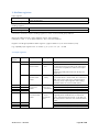
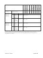
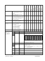
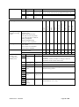
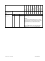
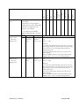
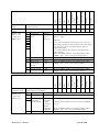
1
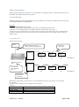
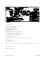
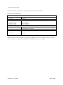
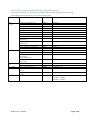
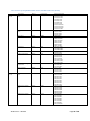
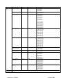
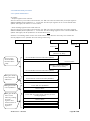
Design guide
Modbus Interface DIII
EKMBDXA7V1
Design guide Modbus Interface DIII
EKMBDXA7V1
Table of Contents
Safety Precautions ......................................................................................................................................3
1. Introduction .............................................................................................................................................3
1.1 System layout ....................................................................................................................................3
1.2 Limitations .........................................................................................................................................4
1.3 Specifications ....................................................................................................................................4
1.3.1 Dimensions and field wiring .......................................................................................................5
1.3.2 Wiring diagram ...........................................................................................................................6
1.3.3 LED meaning ..............................................................................................................................6
1.3.4 Termination resistance ...............................................................................................................6
1.3.5 Push buttons ..............................................................................................................................6
1.3.6 Dipswitch meaning .....................................................................................................................7
1.4 Overview of compatible Daikin units ranges with DIII connection ...................................................8
1.4.1 Overview of compatible Daikin models with DIII connection (detail) ......................................10
1.5 Overview of compatibilty with other DIII centralised control equipment ........................................14
2. Modbus communication .......................................................................................................................15
2.1 Modbus Interface DIII settings ........................................................................................................15
2.2 Communication format ...................................................................................................................16
2.2.1 Function format ........................................................................................................................16
2.2.2 Character format ......................................................................................................................19
2.2.3 Silent internal time ....................................................................................................................19
2.2.5 Response time .........................................................................................................................19
2.3 Communication procedure .............................................................................................................20
2.3.1 System initialisation ..................................................................................................................20
2.3.2 Monitor and operate units from the BMS.................................................................................21
2.3.3 Other DIII devices exist in the same system ............................................................................25
3. Modbus registers ..................................................................................................................................26
3.1. Input registers ................................................................................................................................26
3.2 Holding registers .............................................................................................................................37
4. Software of Modbus Interface DIII ........................................................................................................45
4.1 Software releases ............................................................................................................................45
4.2 Software update with Updater ........................................................................................................45
4.2.1 Updater.....................................................................................................................................45
4.2.2 Method 1) Update with the PC USB cable EKPCCAB3. .........................................................47
4.2.3 Method 2) Update with a USB/RS485 converter. ....................................................................49
4P357732-1 – 2014.04
Page 1 of 58
5. Modbus Interface DIII test operation ....................................................................................................51
5.1 Introduction .....................................................................................................................................51
5.2 Outline of system ............................................................................................................................51
5.3 Test Operation Procedure...............................................................................................................52
5.3.1 Prepare register groups ...........................................................................................................52
5.3.2 Start reading registers groups .................................................................................................55
5.3.3 Set a holding register ...............................................................................................................56
6. Trouble shooting ...................................................................................................................................57
7. Revision of the document .....................................................................................................................58
4P357732-1 – 2014.04
Page 2 of 58
Safety Precautions
Before performing design, construction, or maintenance thoroughly, read the “Safety Precautions” in the
installation manual provided with the product.
1. Introduction
A Building Manangement System (BMS) can control Daikin units through the Modbus protocol by using
the Modbus Interface DIII EKMBDXA7V1
Glossary:
- BMS: Building Management System
- DIII unit: Unit with DIII communication connected to the Modbus Interface DIII.
- DIII device: A centralised device from Daikin with DIII communication (e.g. iTM, …)
- Indoor unit: As the main target is to monitor and control VRV connected indoor units, the DIII units are
referred to as indoor units. For some systems the connected DIII units are in reality outdoor units (e.g.
Applied units)
1.1 System layout
Typical setup (eg VRV)
BMS
RS485 Modbus protocol
2 wire, max wire length 500m
DIII indoor
connection
Outdoor
Modbus Interface
DIII
One Modbus
slave address
(e.g. 1)
Indoor
Indoor
1-00
1-01
Indoor
Indoor
1-03
1-04
Indoor
1-02
DIII address
Outdoor
Indoor
1-05
DIII address
DIII outdoor
connection
DIII address (Group NO) needs to be set on an individual indoor unit or group by the connected
userinterface.
Functions of each Indoor unit in a range for each register:
Example:
Register address
DIII address functions
31001 – 31003
1-00
31004 - 31006
1-01
…
…
4P357732-1 – 2014.04
Page 3 of 58
1.2 Limitations
The number of control commands per indoor unit is limited to 7000 per year.
If the BMS controls the units by using an automatic control program, please make sure it doesn’t exceed
this limitation.
1.3 Specifications
Daikin equipment
connection
BMS equipment protocol
Installation place
Operation condition
Dimensions
Mass (Weight)
Power supply
DIII net (F1F2)
maximum 64 indoor units (groups) and maximum 10 outdoors (addr 1-00 till 4-15)
Modbus RS485 (2 wire, max 500m)
Indoor installation
Temp range 0 till 60°C
379 x 87 x 124 mm
2,1 kg
220 – 240 VAC 50 Hz
Software
The Modbus Interface DIII software can be updated with the Daikin Updater PC
software
Refer to chapter “4.2 Software update with Updater” for details
Installation manual
Design guide
Provided with the option
Latest version available on:
http://www.daikineurope.com/support-and-manuals/product-information
4P357732-1 – 2014.04
Page 4 of 58
1.3.1 Dimensions and field wiring
Refer to installation manual
4P357732-1 – 2014.04
Page 5 of 58
1.3.2 Wiring diagram
1.3.3 LED meaning
During normal operation (application is running):
H1P: DIII communication (sent)
H2P: DIII communication (receive)
H3P: RS485 communication (sent)
H4P: RS485 communication (receive)
H5P H6P H7P: no meaning
HAP: blinking at 400ms = application is running
During uploading of new software (firmware is running)
H1P till H7P: Progress indication (0 till 100%)
HAP: blinking at 200ms = firmware is running.
1.3.4 Termination resistance
By factory default the termination resistance is 0 Ohm (SS2=Off & SS3 =Off)
SS2 On = 120 Ohm
SS3 On = 100 Ohm
(SS2 = On & SS3 = On, not allowed)
Please slide the SS2 or SS3 to the on position to set required termination resistance value of the RS485
line.
1.3.5 Push buttons
BS1 till BS5 have no meaning
4P357732-1 – 2014.04
Page 6 of 58
1.3.6 Dipswitch meaning
Attention: Dipswitch on/off status is detected during power on of the PCB only.
Dipswitch DS1 & DS2 setting:
RS485 Modbus communication speed
DS1 pin 2:Off
9600 bps
DS1 pin 2:On
19200 bps
Modbus communication parity / stop bit
DS1 pin 3:Off 4:Off
Even 1 stop bit
DS1 pin 3:Off 4: On
Odd 1 stop bit
DS1 pin 3:On 4:Off
None 2 stop bit
DS1 pin 3:On 4:On
None 1 stop bit
Modbus address setting
DS2 pin 1/2/3/4
When Modbus address is set (eg 1..15), then modbus RS485
communication is enabled.
Off/Off/Off/Off
No Modbus address is set, meaning no modbus RS485 communication
Off/Off/Off/On
Address 1
Off/Off/On/Off
Address 2
…
On/On/On/On
Address 15
Attention:
During software upload with updater PC program via RS485 port a specific dipswitch setting is required.
Refer to chapter “4.2.3 Method 2) Update with a USB/RS485 converter.” for details.
4P357732-1 – 2014.04
Page 7 of 58
1.4 Overview of compatible Daikin units ranges with DIII connection
For details see chapter “1.4.1 Overview of compatible Daikin models with DIII connection (detail)”
The Modbus Interface DIII can be connected to following units:
description
Brand
model range
VRV
(F1,F2)
HRV
VRV Hydro
box
Air curtains
Heating
Applied
round flow -cassette 3x3
4Way blow cassette 2x2
2Way blow cassette
Corner cassette
Duct - small
Duct - slim
Duct - standard
Duct - high ESP
1Way blow cassette ceiling
suspended
4Way blow cassette ceiling
suspended
Wall mount
Floor standing - concealed
Floor standing - free standing
Heat reclaim ventilation
Heat reclaim ventilation
Heat reclaim ventilation, air
processing
and humidification
Heat reclaim ventilation, air
processing
LT
HT
for connection to VRV
Daikin Altherma Flex - small
indoor
Daikin Altherma Flex - large
indoor
Inverter chillers
4P357732-1 – 2014.04
Daikin
Daikin
Daikin
Daikin
Daikin
Daikin
Daikin
Daikin
Daikin
FXFQ –A
FXZQ –A
FXCQ -A
FXKQ –M
FXDQ -M
FXDQ -P
FXSQ – P7
FXMQ –A
FXHQ –A
Daikin
FXUQ –A
Daikin
Daikin
Daikin
Daikin
Daikin
Daikin
FXAQ –P
FXNQ –P
FXLQ –P
VAM…FA
VAM…FB
VKM…GBM
Daikin
VKM…GB
Daikin
Daikin
Biddle
Daikin
HXY…A
HXHD…A
CYVS/M/L –DK
EKHVM RD/YD...AAV1
Daikin
EKHBRD…ACV1/Y1
Daikin
EWAQ016~064BA
EWYQ016~064BA
SEHVX20~64AAW
Page 8 of 58
Following modelranges can only be combined in a setup with at least one VRV unit or with at least one
other DIII device (eg iTM/…)
description
Sky air
(F1,F2)
split (via
KRP928BB2S)
ERQ - control
box
(connection to
3rd party
AHU)
Brand
model range
round flow -cassette 3x3
Daikin
FCQ(H)G –F
4Way blow cassette 2x2
Daikin
FFQ –C
Hotel duct
Daikin
FDBQ –B
Duct
Daikin
FBQ – C8
Large duct
Daikin
FDQ –B/C
Wall mount
Daikin
FAQ –C
ceiling suspended
Daikin
FHQ –C
4-way blow ceiling suspended
Daikin
FUQ –C
Floor standing
Daikin
FVQ –C
All split models that are compatible with KRP928BB2S
Pair - X + Y + W control
Pair - Z control
Multi
Air curtain
4P357732-1 – 2014.04
Daikin
Daikin
Daikin
Biddle
EKEQFCB(A)V3
EKEQDCBV3
EKEQMCB(A)V3
CYQS/M/L –DK
Page 9 of 58
1.4.1 Overview of compatible Daikin models with DIII connection (detail)
Sky air
(F1,F2)
VRV
(F1,F2)
description
round flow –cassette
3x3
Brand
Daikin
model range
FCQ(H)G
4Way blow cassette
2x2
Daikin
FFQ
Hotel duct
Duct
Daikin
Daikin
FDBQ
FBQ
Large duct
Daikin
FDQ
Wall mount
Daikin
FAQ
ceiling suspended
Daikin
FHQ
4-way blow ceiling
suspended
Daikin
FUQ
Floor standing
Daikin
FVQ
round flow –cassette
3x3
Daikin
FXFQ
4Way blow cassette
2x2
Daikin
FXZQ
2Way blow cassette
Daikin
FXCQ
4P357732-1 – 2014.04
Supported models
FCQG100FVEB
FCQG125FVEB
FCQG140FVEB
FCQG35FVEB
FCQG50FVEB
FCQG60FVEB
FCQG71FVEB
FCQHG100FVEB
FCQHG125FVEB
FCQHG140FVEB
FCQHG71FVEB
FFQ25C2VEB
FFQ35C2VEB
FFQ50C2VEB
FFQ60C2VEB
FDBQ25B8V1
FBQ100C8VEB
FBQ125C8VEB
FBQ140C8VEB
FBQ35C8VEB
FBQ50C8VEB
FBQ60C8VEB
FBQ71C8VEB
FDQ125C7VEB
FDQ200B8V3B9
FDQ250B8V3B9
FAQ71CVEB
FAQ100CVEB
FHQ35CAVEB
FHQ50CAVEB
FHQ60CAVEB
FHQ71CAVEB
FHQ100CAVEB
FHQ125CAVEB
FHQ140CAVEB
FUQ71CVEB
FUQ100CVEB
FUQ125CVEB
FVQ71CVEB
FVQ100CVEB
FVQ125CVEB
FVQ140CVEB
FXFQ100AVEB
FXFQ125AVEB
FXFQ20AVEB
FXFQ25AVEB
FXFQ32AVEB
FXFQ40AVEB
FXFQ50AVEB
FXFQ63AVEB
FXFQ80AVEB
FXZQ15A2VEB
FXZQ20A2VEB
FXZQ25A2VEB
FXZQ32A2VEB
FXZQ40A2VEB
FXZQ50A2VEB
FXCQ20AVEB
FXCQ25AVEB
FXCQ32AVEB
FXCQ40AVEB
FXCQ50AVEB
FXCQ63AVEB
FXCQ80AVEB
FXCQ125AVEB
Page 10 of 58
VRV
(F1,F2)
split (via
KRP928BB2S)
description
Corner cassette
Brand
Daikin
model range
FXKQ
Duct - small
Daikin
FXDQ –M
Duct - slim
Daikin
FXDQ –P
Duct - standard
Daikin
FXSQ
Duct - high ESP
Daikin
FXMQ
1Way blow cassette
ceiling suspended
Daikin
FXHQ
4Way blow cassette
ceiling suspended
Wall mount
Daikin
FXUQ
Daikin
FXAQ
Floor standing –
concealed
Daikin
FXNQ
Floor standing – free
standing
Daikin
FXLQ
Supported models
FXKQ25MVE
FXKQ32MVE
FXKQ40MVE
FXKQ63MVE
FXDQ20M9V3B
FXDQ25M9V3B
FXDQ15P2VE
FXDQ20P2VE
FXDQ25P2VE
FXDQ32P2VE
FXDQ40P2VE
FXDQ50P2VE
FXDQ63P2VE
FXDQ15A2VEB
FXDQ20A2VEB
FXDQ25A2VEB
FXDQ32A2VEB
FXDQ40A2VEB
FXDQ50A2VEB
FXDQ63A2VEB
FXSQ100P7VEB
FXSQ125P7VEB
FXSQ140P7VEB
FXSQ20P7VEB
FXSQ25P7VEB
FXSQ32P7VEB
FXSQ40P7VEB
FXSQ50P7VEB
FXSQ63P7VEB
FXSQ80P7VEB
FXMQ100P7VEB
FXMQ125P7VEB
FXMQ140P7VEB
FXMQ20P7VEB
FXMQ25P7VEB
FXMQ32P7VEB
FXMQ40P7VEB
FXMQ50P7VEB
FXMQ63P7VEB
FXMQ80P7VEB
FXHQ100AVEB
FXHQ32AVEB
FXHQ63AVEB
FXUQ100AVEB
FXUQ71AVEB
FXAQ15PAV1
FXAQ20PAV1
FXAQ25PAV1
FXAQ32PAV1
FXAQ40PAV1
FXAQ50PAV1
FXAQ63PAV1
FXNQ20P2VEB
FXNQ25P2VEB
FXNQ32P2VEB
FXNQ40P2VEB
FXNQ50P2VEB
FXNQ63P2VEB
FXLQ20P2VEB
FXLQ25P2VEB
FXLQ32P2VEB
FXLQ40P2VEB
FXLQ50P2VEB
FXLQ63P2VEB
All split models that are compatible with KRP928BB2S
4P357732-1 – 2014.04
Page 11 of 58
description
Heat reclaim ventilation
Brand
Daikin
model range
VAM…FA
Heat reclaim ventilation
Daikin
VAM…FB
Heat reclaim
ventilation, air
processing
and humidification
Heat reclaim
ventilation, air
processing
LT
Daikin
VKM…GBM
Daikin
VKM…GB
Daikin
HXY…A
HT
Daikin
HXHD…A
Air curtains
for connection to VRV
Biddle
CYV
ERQ – control
box
(connection to
3rd party AHU)
Pair - X + Y + W
control
Pair - Z control
Multi
Air curtain
Daikin
EKEQFCB(A)V3
Daikin
Daikin
Biddle
EKEQDCBV3
EKEQMCB(A)V3
CYQ
HRV
VRV Hydro box
4P357732-1 – 2014.04
Supported models
VAM1000FA5VE1
VAM1500FA5VE1
VAM2000FA5VE1
VAM350FA5VE1
VAM500FA5VE1
VAM650FA5VE1
VAM800FA5VE1
VAM1000FB7VE
VAM1500FB7VE
VAM2000FB7VE
VAM350FB7VE
VAM500FB7VE
VAM650FB7VE
VAM800FB7VE
VKM100GBMV1
VKM50GBMV1
VKM80GBMV1
VKM100GBV1
VKM50GBV1
VKM80GBV1
HXY080A7V1B
HXY125A7V1B
Only compatible from new software integration onwards:
(sw Idxxxx, & production implantation date & design digit)
HXHD125A7V1B (ID3221, 04/2014, design digit 4)
CYVS/M100DK80*BC
CYVS/M 100DK80*SC
CYVS/M 150DK80*BC
CYVS/M 150DK80*SC
CYVS/M 200DK100*BC
CYVS/M 200DK100*SC
CYVS/M 250DK140*BC
CYVS/M 250DK140*S
CYVL100DK125*BC
CYVL100DK125*SC
CYVL150DK200*BC
CYVL150DK200*SC
CYVL200DK250*BC
CYVL200DK250*SC
CYVL250DK250*BC
CYVL250DK250*SC
EKEQFCB(A)V3
EKEQDCBV3
EKEQMCB(A)V3
CYQS150DK80*BN/*SN
CYQS200DK100*BN/*SN
CYQS250DK140*BN/*SN
CYQM100DK80*BN/*SN
CYQM150DK80*BN/*SN
CYQM200DK100*BN/*SN
CYQM250DK140*BN/*SN
CYQL100DK125*BN/*SN
CYQL150DK200*BN/*SN
CYQL200DK250*BN/*SN
CYQL250DK250*BN/*SN
Page 12 of 58
Heating
Applied
description
Brand
model range
Supported models
Daikin Altherma Flex small indoor
Daikin
EKHVM RD/YD...AAV1
Daikin Altherma Flex large indoor
Daikin
EKHBRD…ACV1/Y1
Daikin
EWAQ016~064BAW*
EWYQ016~064BAW*
SEHVX20~64AAW
Only compatible from new software integration onwards:
(sw IDxxxx, & production implantation date & design digit)
EKHVMRD50AAV1(ID 3221, 04/2014, design digit 6)
EKHVMRD80AAV1( ID 3221, 04/2014, design digit 6)
EKHVMYD50AAV1(ID 3221, 04/2014, design digit 6)
EKHVMYD80AAV1(ID 3221, 04/2014, design digit 5)
Only compatible from new software integration onwards:
(sw IDxxxx, & production implantation date & design digit)
EKHBRD011ACV1 (ID 3221, 04/2014, design digit 7)
EKHBRD011ACY1 (ID 3221 *)
EKHBRD014ACV1 (ID 3221, 04/2014 , design digit 7)
EKHBRD014ACY1 (ID 3221 *)
EKHBRD016ACV1 (ID 3221, 04/2014, design digit 7)
EKHBRD016ACY1 (ID3221 *)
* planned to implement in mass production (M/2014) At the
moment it is executed in mass production, the design digits
will be added.)
Only compatible from new software integration onwards:
(sw IDxxxx, & production implantation date & design digit)
(ID 4044, 07/2014, design digit 4)*
(ID 4044, 07/2014, design digit 4)*
(ID 4044, 07/2014, design digit 3)*
* “Negative cooling leaving water setpoint” not yet available
at present moment in the unit: an update of user interface
software (BRC21A52 => BRC21A53) is planned in near
future to enable this feature (M/2014). At the moment it is
executed in mass production, the design digits will be
added.
Inverter chillers
4P357732-1 – 2014.04
Page 13 of 58
EKMBDXA7V1
Modbus Interface DIII
DST301BA61
Schedule timer
(*1)
DCS301BA61
Unified ON/OFF
controller
DCS302CA61
Central Remote
controller
DCS303A51
Residential central
remote controller
DCS601C51
Intelligent Touch
Controller
DMS502B51
Interface for use in
BACnet®
DMS504B51
Interface for use in
LonWorks®
DCM601A51
Intelligent Touch
Manager
1.5 Overview of compatibilty with other DIII centralised control equipment
Intelligent Touch
Manager
DCM601A51
OK
OK
OK
NG
NG
OK
OK
NG
OK
Interface for use in
LonWorks®
DMS504B51
OK
NG
NG
OK
NG
OK
OK
NG
NG
Interface for use in
BACnet®
DMS502B51
OK
NG
NG
OK
NG
OK
OK
NG
NG
Intelligent Touch
Controller
DCS601C51
NG
OK
OK
OK
NG
OK
OK
NG
OK
Residential central
remote controller
DCS303A51
NG
NG
NG
NG
NG
NG
NG
NG
NG
Central Remote
controller
DCS302CA61
OK
OK
OK
OK
NG
OK
OK
OK
OK
Unified ON/OFF
controller
DCS301BA61
OK
OK
OK
OK
NG
OK
OK
OK
OK
Schedule timer
(*1)
DST301BA61
NG
NG
NG
NG
NG
OK
OK
NG
NG
Modbus Interface
DIII
EKMBDXA7V1
OK
NG
NG
OK
NG
OK
OK
NG
NG
(*1): The schedule timer should be used in combination with the central remote controller or unified
ON/OFF controller
•
•
If using in combination with centralized control equipment, the relation between both
central remote controllers is last command priority.
if using in combination with centralized control equipment, the remote control mode is
decided by the setting of the highest priority item in the priority rank.
Priority ranking of Modbus Interface DIII:
No priority ranking is implemented. Meaning, in case another D-BACS device is detected, the lock button
& force OFF functions are not available.
4P357732-1 – 2014.04
Page 14 of 58
2. Modbus communication
2.1 Modbus Interface DIII settings
Communication protocol
Modbus RTU
(according to “Modicon Modbus Protocol reference
guide” PI-MBUS-300 Rev J)
Communication speed
9600 bps
Or 19200 bps
Parity / stop bit
Even 1 stop bit
Odd 1 stop bit
None 2 stop bit
None 1 stop bit
One dedicated modbus
1..15
address setting
Implemented function
codes
Data types
Register addresses
4P357732-1 – 2014.04
Dipswitch setting
DS1 pin 2:Off
DS1 pin 2:On
DS1 pin 3:Off 4:Off
DS1 pin 3:Off 4: On
DS1 pin 3:On 4:Off
DS1 pin 3:On 4:On
DS2 pin 1/2/3/4
Addr 1: Off/Off/Off/On
Addr 2: Off/Off/On/Off
…
Addr 15: On/On/On/On
0x03
Read Holding Registers (broadcast support)
0x04
Read Input Registers (broadcast support)
0x06
Preset Single Registers (No broadcast support)
0x10
Preset Multiple Registers (No broadcast support)
(remark: Holding Registers will not reflect the actual value)
(other function codes are treated as illegal function and
return an exception response)
Input Register:
Length 16 bits, Address range: 30001 - 39999
Holding Register
Length 16 bits, Address range: 40001 – 49999
(Data larger than 16 bits can be handled by assigning
continuous addresses to registers.)
Same address meaning for each applicable model
Page 15 of 58
2.2 Communication format
2.2.1 Function format
(1) Read Input Registers (0x04)
[Function]
Read values of input registers. The address and the content of input registers are described in
3. Modbus registers
[Query]
The query message specifies the start address of the register and the number of registers. The register
address starts at zero: register 30001 is addressed as 0.
This function can read up to 32 registers in one query.
Here is an example of a request to slave address 1 for reading 3 register values starting from register
31001.
Query
Field
Slave Address
Function Code
Start Address(Upper)
Start Address(Lower)
Number of Registers(Upper)
Number of Registers(Lower)
Error Check CRC16(Lower)
Error Check CRC16(Upper)
4P357732-1 – 2014.04
Data
0x01
0x04
0x03
0xE8
0x00
0x03
0x30
0x7B
Response
Field
Slave Address
Function Code
Data Size(Bytes)
Data1(Upper)
Data1(Lower)
Data2(Upper)
Data2(Lower)
Data3(Upper)
Data3(Lower)
Error Check CRC16(Lower)
Error Check CRC16(Upper)
Data
0x01
0x04
0x06
0xXX
0xXX
0xXX
0xXX
0xXX
0xXX
0xXX
0xXX
Page 16 of 58
(2) Preset Single Register (0x06)
[Function]
Write a value to a holding register. In case of broadcast, the value is written to the same holding register
of all slave units. The address and the content of the holding registers are described in
3. Modbus registers
[Query]
The query message specifies the start address of the register and a value. The register address starts at
zero: register 40001 is addressed as 0. Here is an example of a request to slave address 1 for writing the
value ‘2’ to register 42002.
Query
Field
Slave Address
Function Code
Address(Upper)
Address(Lower)
Value(Upper)
Value (Lower)
Error Check CRC16(Lower)
Error Check CRC16(Upper)
Data
0x01
0x06
0x07
0xD1
0x00
0x02
0x59
0x46
Response
Field
Slave Address
Function Code
Address(Upper)
Address(Lower)
Value(Upper)
Value (Lower)
Error Check CRC16(Lower)
Error Check CRC16(Upper)
Data
0x01
0x06
0x07
0xD1
0x00
0x02
0x59
0x46
(3) Preset Multiple Registers (0x10)
[Function]
Write values to holding registers. In case of broadcast, the values are written to the same holding
registers of all slave units. The address and the content of holding registers are described in
3. Modbus registers
[Query]
The query message specifies the start address of the register, size of data and values. The register
address starts at zero: register 40001 is addressed as 0. This function can write up to 30 registers in one
query. Here is an example of a request to slave address 1 for writing 2 values to register 42001 and to
register 42002.
Query
Field
Slave Address
Function Code
Start Address(Upper)
Start Address(Lower)
Number of Registers(Upper)
Number of Registers(Lower)
Data Size(bytes)
Value1(Upper)
Value1(Lower)
Value2(Upper)
Value2(Lower)
Error Check CRC16(Lower)
Error Check CRC16(Upper)
4P357732-1 – 2014.04
Data
0x01
0x10
0x07
0xD0
0x00
0x02
0x04
0x00
0x10
0x00
0x01
0x18
0xC6
Response
Field
Slave Address
Function Code
Start Address(Upper)
Start Address(Lower)
Number of Registers(Upper)
Number of Registers(Lower)
Error Check CRC16(Lower)
Error Check CRC16(Upper)
Data
0x01
0x10
0x07
0xD0
0x00
0x02
0x41
0x45
Page 17 of 58
(4) Exception response
In case the query message is faulty, the Modbus Interface DIII will reply an exception response. In normal
conditions the function code of the response message is the same as the query message. But in case of
an error, 0x80 is added to the function code of the response message.
The exception response includes the exception code, indicating the cause of the error.
Exception code
0x01
0x02
Name
Illegal function
Illegal data address
0x03
Illegal data
Cause
This function code is not supported.
Access was attempted to an unassigned register
address.
This query includes unauthorized data.
[Example of exception response]
In the case of setting an illegal mode to the holding register address 42002.
Query
Field
Slave Address
Function Code
Start Address(Upper)
Start Address(Lower)
Number of Registers(Upper)
Number of Registers(Lower)
Error Check(Lower)
Error Check(Upper)
4P357732-1 – 2014.04
Data
0x01
0x06
0x07
0xD1
0x01
0x0F
0x99
0x13
Response
Field
Slave Address
Function Code
Exception Code
Error Check(Lower)
Error Check(Upper)
Data
0x01
0x86
0x03
0x02
0x61
Page 18 of 58
2.2.2 Character format
Each byte of a message is sent as character data as follows.
A character consists of start bit (0), 8 bits data, parity bit and stop bit (1). One character size is always 11
bits and stop bit 1 or 2 is selected by parity bit.
[Non Parity]
0 (LSB)
Start bit
1
2
3
4
5
Data
6
7
8
9
Stop bit 1
10 (MSB)
Stop bit 2
1
2
3
4
5
Data
6
7
8
9
Parity bit
(Odd or
Even)
10 (MSB)
Stop bit 2
[Parity]
0 (LSB)
Start bit
2.2.3 Silent internal time
Every frame needs to have silent interval time (T1-T2-T3-T4) before and after. The silent interval time is
depending on communication speed.
Baud Rate(bps)
9600
19200
Silent Interval Time(ms)
5
2,5
(T1-T2-T3-T4)
2.2.5 Response time
This Modbus Interface DIII responds a message after response time(t1) when this Modbus Interface DIII
receives a query message. The response time(t1) of this adaptor is “Silent Interval Time(T1-T2-T3-T4) +
20ms”.
Modbus master needs to wait to send next query message for time interval(t2) when the modbus master
receives a response from the Modbus Interface DIII. The time interval(t2) should be more than “Silent
Interval Time(T1-T2-T3-T4) + 20ms”.
Modbus master
Query message
Query message
Response
Modbus Interface DIII
t1
t1 = (T1-T2-T3-T4) + 20 (ms)
4P357732-1 – 2014.04
t2
t2 >= (T1-T2-T3-T4) + 20 (ms)
Page 19 of 58
2.3 Communication procedure
2.3.1 System initialisation
At startup:
- All input registers have values 0.
After the discovery of the DIII connected units, the “DIII unit connected status bit” (see Input registers
30002 till 30006) will be updated to “1: connected“ and the input registers of the connected DIII units
(30001 and higher) will have the correct values.
- All the holding registers have initial values 0.
After the discovery of the DIII connected units, the “DIII unit connected status bit” (see input registers
30002 till 30006) will be updated to “1: connected” and the holding registers of the connected DIII units
(42001 and higher) will be updated to the actual values once.
Attention: The holding values receive the actual values at the detection time only. This means this
will only happen once. (Remark: also not during rediscovery)
BMS
Modbus Interface DIII
DIII unit
Power on
Power on
Modbus Interface DIII status
(30001 bit 0): Busy
Check status
when Modbus
Interface DIII is
ready
Check Modbus Interface DIII status (30001)
Return: Busy
Retrieve status
Modbus Interface DIII status
(30001 bit 0): Ready
Check Modbus Interface DIII status (30001)
Return: Ready
BMS gets all DIII
units connected
addresses
Check DIII unit connected status (30002-5)
Return: Ready
BMS gets all DIII
units capabilities
BMS gets all DIII
units current
status by reading
the input
registers and
read all values of
the holding
registers
Check DIII unit capabilities
Return values
Check DIII unit status (input registers) & read
holding registers
4P357732-1 – 2014.04
Return values
Page 20 of 58
2.3.2 Monitor and operate units from the BMS
Input registers of each DIII unit: 30001 and higher
The input registers will contain the status of the connected DIII units.
In case the DIII communication is interrupted (see Input registers 30006 till 30009): then the last
communicated values will remain, until the DIII communication is restored.
Status changes are communicated continuously to the input registers, meaning the input registers will
contain the actual values.
Holding registers of each DIII unit: 42001 and higher
- Writing instructions to change a unit status (Preset Single or Multiple Registers)
When a value is written to a holding register, it will be communicated to the DIII units.
Attention: Modbus Interface DIII sends the command to a unit when the value of a Holding Register is
changed. Especially in case that indoor units are operated from the user interface, the BMS should
always get the status of indoor units and copy the received status to the Holding Registers.
Note: at start-up of the system (See 2.3.1 System initialisation) and the initial discovery of the DIII
connected units, the Modbus Interface DIII put the actual status in the holding registers. (Remark: not
during rediscovery.)
BMS
BMS checks
communication
status
Copy:
BMS gets all DIII
units current
status by reading
the input
registers and
copies to the
related bits (preset) to the
holding registers
Modbus Interface DIII
DIII unit
Check communication status (30006-9)
Return: status
Get DIII unit status (input registers)
Return values
Command:
BMS changes a
value in the
holding registers
4P357732-1 – 2014.04
Preset DIII unit status to the holding register
Preset On/Off bit to the holding register
Change on/off
Page 21 of 58
Step by step explanation of the required copy of the BMS.
Below is an example for On/Off operation.
Note: The interval setting to the same register is over 0.5s.
[Legend]
BMS
Setting status
Modbus Interface DIII
Modbus
Received status
Holding register
present value
Holding register
The last value
User
interface
Unit
DIII
Status
Input Register
Status
[On/Off operation sequence example]
1. The BMS receives the Off status of units (1) and copies the input status to Holding registers (2).
BMS
Off
Off
Modbus Interface DIII
(2) Off
Off
Unit
Off
Off
Off
(1) Off
User
interface
Off
2. The BMS sends an On command to the unit.
BMS
On
Modbus Interface DIII
On
On
-
Off
On
On
User
interface
Unit
On
On
On
The value of the holding register is changed. So the Modbus Interface
DIII sends the command to the units.
3. The BMS gets the status of the input register (1) and copies the received status to the holding
registers (2).
BMS
On
Modbus Interface DIII
(2) On
On
On
On
On
Unit
User
interface
On
On
(1) On
4P357732-1 – 2014.04
Page 22 of 58
4. The unit is switched Off by the user interface.
BMS
Modbus Interface DIII
On
-
User
interface
Unit
On
Off
Off
On
Off
Off
5. The BMS gets the status of the input register (1) and copies the received status to the holding
registers (2).
BMS
Modbus Interface DIII
(2) Off
Off
Off
Off
On
(3) Off
Off
Off
(1) Off
User
interface
Unit
Off
The value of the holding register is changed. So the Modbus Interface
DIII sends the command to the units (3).
6. The BMS sends an On command to the unit.
BMS
Modbus Interface DIII
On
On
On
Off
On
Unit
On
On
-
User
interface
On
On
The value of the holding register is changed. So the Modbus Interface
DIII sends the command to the units.
7. The BMS gets the status of the input register (1) and copies the received status to the holding
registers (2).
BMS
On
On
4P357732-1 – 2014.04
Modbus Interface DIII
(2) On
(1) On
On
On
On
Unit
User
interface
On
On
Page 23 of 58
Attention: In case the BMS does not copy (see 5.) and sends an On command to the unit.
Then the requested On command will not be executed.
Status
BMS
Modbus Interface DIII
-
On
-
Unit
On
User
interface
Off
Off
Off
The BMS sends an On command to the unit.
BMS
Modbus Interface DIII
On
On
On
On
On
On
-
Unit
User
interface
Off
Off
The value of the holding register is not changed. So the Modbus
Interface DIII does not send the command to the units.
4P357732-1 – 2014.04
Page 24 of 58
2.3.3 Other DIII devices exist in the same system
(See 1.5 Overview of compatibilty with other DIII centralised control equipment)
No priority ranking is implemented. Meaning in case another DIII device is detected, the lock button &
force OFF functions are not available.
BMS
Modbus Interface DIII
Other DIII device (e.g.
iTM)
Power on
Other DIII device exists
(30001 bit 1): No
(Forced OFF functions &
lock functions available)
BMS can use
Forced OFF
functions and
lock functions
Check Other DIII device exists (30001)
Return: No
Power on
Detect other DIII
device
Other DIII device exists
(30001 bit 1): Yes
(Forced OFF functions &
lock functions not available)
Check Other DIII device exists (30001)
BMS cannot use
Forced OFF
functions and
lock functions
4P357732-1 – 2014.04
Return: Yes
Page 25 of 58
3. Modbus registers
Input registers
30001 till 30009
31001 and higher
General Modbus Interface DIII status (incl. Detected DIII units & communication
status of DIII units)
Individual DIII units information
Holding registers
41001
42001 and higher
Modbus Interface DIII central “forced off”
Individual DIII units instructions
Calculation method for input & holding registers of each connected DIII group address:
DIII group address has an “upper address” and a “lower address”.
Example for 1-00: “1” is the upper address, “00” is the lower address.
Register of a DIII group address: Base register+((upper address-1)*16+lower address)*step
E.g. capability input register for 4-15: 31001+((“4”-1)*16+”15” )*3 = 31190
3.1. Input registers
Input
register
30001
Bit
Description
Meaning
15..2
1
Other DIII
device exists
0: No
1: Yes
0
Modbus
Interface DIII
status
0: Busy
1: ready
DIII unit
connected
status
0: not
connected
1: connected
DIII unit
communication
status
0: Normal
1: Communication
error
30002
30003
30004
30005
30006
15..0
15..0
15..0
15..0
15..0
30007
30008
30009
15..0
15..0
15..0
4P357732-1 – 2014.04
Note: When another DIII device is connected
or disconnected to the DIII, it can take up till
10 minutes to update the status of the input
register.
(Remark: Initially delivered from factory the
value is 1)
Typical at power on of the option, the DIII
communication is started with the connected
DIII units. At the end of the communication
start up, all the input registers and holding
resisters have the correct initial values.
DIII address 1-00 (bit 0) till 1-15 (bit 15)
DIII address 2-00 (bit 0) till 2-15 (bit 15)
DIII address 3-00 (bit 0) till 3-15 (bit 15)
DIII address 4-00 (bit 0) till 4-15 (bit 15)
DIII address 1-00 (bit 0) till 1-15 (bit 15)
Typically when a DIII device is connected
once, and then disconnected: it can take up
till 10 minutes to discover the communication
error.
DIII address 2-00 (bit 0) till 2-15 (bit 15)
DIII address 3-00 (bit 0) till 3-15 (bit 15)
DIII address 4-00 (bit 0) till 4-15 (bit 15)
Page 26 of 58
31001 (1-00)
31004 (1-01)
.. (step of 3)
31190 (4-15)
11
10
9
8
7
6
5
4
3
2
1
0
4P357732-1 – 2014.04
Fan
direction
capability
Fan
direction
steps
capability
Dry mode
capability
Auto mode
capability
Heating
mode
capability
Cooling
mode
capability
Fan mode
capability
HRV
Split
VRV hydrobox
LT & HT
Air curtains
ERQ control box
Heating
Applied
Fan speed capability(*not split)
Fan speed levels capability(*not
split)
Fan direction capability(*not split)
Fan direction levels capability(*not
split)
Dry mode capability
Auto mode capability
Heating mode capability
Cooling mode capability
Fan mode capability (*not split)
Bit Description Meaning
15 Fan speed
0:Not exist
capability
1: Exist
14 Fan speed
0 till 7
13 steps
12 capability
Sky-air
Indoor unit
capability
VRV
Input register
O
O
-
O*
O
O
O
O
O
This value has only meaning if “Fan speed capability”
exists
0: -, 1:Fix, 2: 2step, 3: 3 step, 4: 4 step, 5: 5 step, 6: , 7: -
0:Not exist
1: Exist
0 till 7
This value has only meaning if “Fan direction
capability” exists
0: -, 1:Fix, 2: 2step, 3: 3 step, 4: 4 step, 5: 5 step, 6: -, 7: -
0:Not exist
1: Exist
0:Not exist
1: Exist
0:Not exist
1: Exist
0:Not exist
1: Exist
0:Not exist
1: Exist
Page 27 of 58
O
O
O*
O
O
O
O
Set point of indoor units range
*for split: fixed values refer to
KRP928BB2S documentation
Bit
Description Meaning
15..8 Unit
- 128 .. 127°C 8 bit signed integer
cooling set
(bit 15= sign)
point
upper limit
7..0 Unit
- 128 .. 127°C 8 bit signed integer
cooling set
(bit 7= sign)
point lower
limit
31003 (1-00)
15..8 Unit
- 128 .. 127°C 8 bit signed integer
31006 (1-01)
heating set
(bit 15= sign)
.. (step of 3)
point
upper limit
31192 (4-15)
7..0 Unit
- 128 .. 127°C 8 bit signed integer
heating set
(bit 7= sign)
point lower
limit
(Note: Unit set point range is depending on unit e.g. 16 till 32°C.
In some user interfaces, it is possible to change the set point range towards the user e.g. 20 till 30°C.
But these values are independent from the unit set point range. Meaning unit set point range values are
not modified. E.g. 16 till 32°C)
Input register
31401 (1-00)
31405 (1-01)
.. (step of 4)
31653 (4-15)
4P357732-1 – 2014.04
HRV
Split
VRV hydrobox
LT & HT
Air curtains
ERQ control box
Heating
Applied
Leaving water set point exist
Low noise capability
Space heating capability
Reheat capability
Bit
Description Meaning
15..6 5
Reheat
0: Not exist
capability
1: exist
4
Space
0: Not exist
heating
1: exist
capability
3
2
Low noise
0: Not exist
capability
1: exist
1
Leaving
0: Not exist
water set
1: exist
point exist
0
-
Sky-air
Indoor unit
capability
-
VRV
Room
temperature set
point range
31002 (1-00)
31005 (1-01)
.. (step of 3)
31191 (4-15)
Applied
Heating
ERQ control box
Air curtains
VRV hydrobox
LT & HT
Split
HRV
Sky-air
VRV
Input register
-
-
-
-
O
-
-
O
O
Page 28 of 58
VRV hydrobox
LT & HT
Air curtains
ERQ control box
Heating
Applied
Bit
15..8
Split
31402 (1-00)
31406 (1-01)
.. (step of 4)
31654 (4-15)
HRV
Leaving water set point range
cooling and heating
Sky-air
Leaving water set
point range
VRV
Input register
-
-
-
-
O
-
-
O
O
Description Meaning
Unit
- 128 .. 127°C 8 bit signed integer
cooling
(unity 1°C)
(bit 15= sign)
water set
point
upper limit
7..0 Unit
- 128 .. 127°C 8 bit signed integer
cooling
(unity 1°C)
(bit 7= sign)
water set
point lower
limit
31403 (1-00)
15..8 Unit
- 128 .. 127°C 8 bit signed integer
31407 (1-01)
heating
(unity 1°C)
(bit 15= sign)
.. (step of 4)
water set
31655 (4-15)
point
upper limit
7..0 Unit
- 128 .. 127°C 8 bit signed integer
heating
(unity 1°C)
(bit 7= sign)
water set
point lower
limit
(Note: Unit set point range is depending on unit e.g. 5 till 20°C.
In some user interfaces, it is possible to change the set point range towards the user e.g. 10 till 15°C.
But these values are independent from the unit set point range. Meaning unit set point range values are
not modified. E.g. 5 till 20°C)
4P357732-1 – 2014.04
Page 29 of 58
32001 (1-00)
32007 (1-01)
.. .. (step of 6)
32379 (4-15)
11
10
9
8
Fan
direction
7
5
Thermo
status
Heater
status
Fan status
4
-
6
4P357732-1 – 2014.04
0 till 7
Air curtains
ERQ control box
Heating
Applied
Fan direction
VRV hydrobox
LT & HT
Fan speed (Air
flow rate)
Split
Indoor status
HRV
“Forced off”
On/Off status of indoor units
* For VRV hydrobox LT & HT &
Heating:
On/off “space cooling/heating”
status and control
“Forced off” status of indoor unit
(for each unit separate) (by T1-T2
or by central “Forced off” from the
Modbus Interface DIII) (HRV: no
“Forced off” status)
Thermostat status
Indoor fan status (if present)
Heater status (if present)
LL, L, M, H, HH (depending on
indoor unit capability)
* Air curtain:
CYV models: not available
CYQ models: available
* HRV (ventilation rate):
VAM models: available
VKM models: not available
Swing, Flap direction (depending
on indoor unit capability)
Bit
Description Meaning
15
14
Fan speed 0 till 7
13
12
Sky-air
On/Off
VRV
Input register
O
O
O
O
O*
O
O
O*
O
O
O
-
O
O
O
O
O
O
O
O
-
O
O
O
O
O
O
O
O
O*
-
-
O*
-
-
-
O
O
-
-
-
-
-
-
-
This value is depending on “fan speed steps
capability” value
Value
0
1
2
3
4
5
6
7
Fix
H
2step
L
H
3step
L
M
H
5step
LL
L
M
H
HH
HRV (ventilation rate):
(note for HRV: fan speed steps capability is fixed to
0)
For VAM units: value 3:L, 7:H
This value has only meaning if “Fan direction
capability” exists
0: P0, 1: P1, 2:P2, 3: P3, 4: P4, 5: -, 6: Stop, 7: swing
P0 = horizontal direction
P4 = vertical direction
0: Off
1: On
0:Off
1: On
0: Off
1: On
Page 30 of 58
3
2
1
0
Forced off
status
On/off
status
0: none
1: Forced off
or Indoor status of “Forced off” of digital input T1-T2
or by central “Forced off” by Modbus Interface DIII
0: Off
1: On
32002 (1-00)
32008 (1-01)
.. .. (step of 6)
32380 (4-15)
13
12
11
10
9
8
7
6
5
4
3
2
1
0
4P357732-1 – 2014.04
Defrost/ hot
start status
Operation
status
0: Off
1: On
Filter sign
status
0: Off
1 till 15: On
Operation
mode
setting
0 till 7
0 till 2
Split
VRV hydrobox
LT & HT
Air curtains
ERQ control box
Heating
Applied
Indoor status
HRV
Filter sign
Depending on indoor unit
capability (fan
only/Cool/heat/auto/dry)
* for split: no fan only mode
* for VRV hydrobox LT&HT &
heating & applied:
Only Heating&Cooling
* for HRV: Only ventilation
Filter sign of indoor units
* Air curtain:
CYV models: not available
CYQ models: available
Defrost/hot start status
Operation status
Cool/heat master
Bit
Description
Meaning
15
Cool/heat
0 till 2
master
14
Sky-air
Cooling/ Heating
Operation setting
mode
VRV
Input register
O
O
O*
O*
O*
O
O
O*
O*
O
O
O
-
-
O*
-
O
-
O
O
-
O
O
O
O
O
O
O
O
-
-
O
O
O
O
O
0: not decided
1: Slave
2: Master (means possible to change cool/heat
operation mode via this indoor unit)
0: Fan, 1: Heating, 2: Cooling
Actual running status.
0: Fan, 1: Heating, 2: Cooling, 3: Auto
4:Ventilation,5:-,6:-,7: Dry
Page 31 of 58
Bit
15..0
4P357732-1 – 2014.04
Description
Set point
Meaning
- 127,9 ..
127,9°C
(unity: 0,1°C)
HRV
Split
VRV hydrobox
LT & HT
Air curtains
ERQ control box
Heating
Applied
Set point of indoor units
Sky-air
Room
temperature set
point
32003 (1-00)
32009 (1-01)
..(step of 6)
32381 (4-15)
VRV
Input register
O
O
-
O
O
O
O
O
-
16 bit signed integer equals the value multiplied by
10
(bit 15= sign)
Page 32 of 58
32005 (1-00)
32011 (1-01)
.. (step of 6)
32383 (4-15)
HRV
Split
VRV hydrobox
LT & HT
Air curtains
ERQ control box
Heating
Applied
Suction temperature of indoor units
(or user interface sensor
temperature)
* Split: KRP928BB2S is required
Bit
Description Meaning
15..0 Room
- 511,9 ..
temperature 511,9°C
(unity: 0,1°C)
Sky-air
Room
temperature
VRV
Input register
O
O
-
O*
O
-
O
O
-
16 bit signed integer equals the value multiplied by
10
(bit 15= sign)
Additional notes concerning the room temperature Or Suction temperature.
By default the Suction temperature value is applicable.
If the room temperature of the user interface (e.g. BRC1E52A/B7 or BRC2/3E52C7) is required, following
settings should be confirmed on the user interface:
Mode No. –
First Code
No.
Description of setting
( ) = group
setting
User interface settings (e.g. BRC1E52A/B7 or BRC2/3E52C7)
1c – 1
Thermostat sensor used for the
"Auto" operation mode and the
Setback function (room temperature on detailed
display).
Unit settings
10 (20) – 2
Thermostat sensor in the remote
controller
10 (20) – 5
Sensor value information to DIII devices
10 (20) – 6
Thermostat sensor in group
control
Required values:
Value 02:
Remote controller
thermistor
Value 03:
Use exclusively
Value 02:
Sensor value as
set by 10-2-0X or 10-6-0X.
Value 02:
Use both the unit sensor (or
remote sensor if installed) AND
the remote controller sensor.
For more information, refer to the installation manual of applicable indoor unit.
4P357732-1 – 2014.04
Page 33 of 58
32801 (1-00)
32805 (1-01)
.. (step of 4)
33053 (4-15)
32802 (1-00)
32806 (1-01)
.. (step of 4)
33054 (4-15)
1.4.1 Overview of compatible
Daikin models with DIII connection
(detail))
Bit
Description Meaning
15..0 Heating
- 127,9 ..
water Set
127,9°C
(unity: 0,1°C)
point
15..0 Cooling
- 127,9 ..
water Set
127,9°C
(unity: 0,1°C)
point
HRV
Split
VRV hydrobox
LT & HT
Air curtains
ERQ control box
Heating
Applied
Leaving water set point cooling
and heating
* Applied: “cooling negative
leaving water set point” feature:
depending if function is integrated
in unit.
(see chapter
Sky-air
Leaving water set
point
VRV
Input register
-
-
-
-
O
-
-
O
O*
16 bit signed integer equals the value multiplied by
10
(bit 15= sign)
16 bit signed integer equals the value multiplied by
10
(bit 15= sign)
Bit
15..8
Description
Storage
set point
7..3
2
Low noise
On/Off
status
Storage
started
request
Reheat
On/Off
status
1
0
4P357732-1 – 2014.04
Meaning
- 128 .. 127°C
(unity 1°C)
HRV
Split
VRV hydrobox
LT & HT
Air curtains
ERQ control box
Heating
Applied
Quiet mode (low
noise)
32803 (1-00)
32807 (1-01)
.. (step of 4)
33055 (4-15)
Reheat enable/ disable status
Storage start requested
Storage set point
Sky-air
Domestic hot
water
VRV
Input register
-
-
-
-
O
-
-
O
-
-
-
-
-
O
-
-
O
O
8 bit signed integer equals the value multiplied by 10
(bit 15= sign)
0: Off
1: On
0: none
1: started
request
0: Off
1: On
Page 34 of 58
4P357732-1 – 2014.04
Heating
Applied
-
ERQ control box
5..0
Air curtains
Description
Ventilation
operation
mode
setting
VRV hydrobox
LT & HT
Bit
15..8
7
6
Split
32804 (1-00)
32808 (1-01)
.. (step of 4)
33056 (4-15 )
HRV
*VAM models: available
VKM models: not available
Sky-air
Ventilation
operation mode
VRV
Input register
-
-
O*
-
-
-
-
-
-
Meaning
1: Auto
2: Energy
reclaim
ventilation
3: Bypass
Page 35 of 58
33601 (1-00)
33603 (1-01)
.. (step of 2)
33727 (4-15)
33602 (1-00)
33604 (1-01)
.. (step of 2)
33728 (4-15)
15
14
13
12
11
10
9
8
7
6
5
4
3
2
1
0
4P357732-1 – 2014.04
HRV
Split
VRV hydrobox
LT & HT
Air curtains
ERQ control box
Heating
Applied
Error, Alarm & Warning status
with code and sub-code
code values in ASCII code
Bit
Description Meaning
15
Error/
ASCII (dec)
alarm/
14
warning
13
code
12
character
11
(higher)
10
9
8
7
Error/
ASCII (dec)
Alarm/
6
warning
5
code
4
character
3
(lower)
2
1
0
Sky-air
Error
VRV
Input register
O
O
O
O
O
O
O
O
O
Example:
0100 0011 0011 0111
Error code character (higher)
01000011 (bin) = 67(dec) = ASCII “C”
Error code character (lower)
00110111 (bin) = 55 (dec) = ASCII “7”
Error code: “C7”
Note: In case no error exists, then following
0011 0000 0011 0000
0011 0000 (bin) = 48(dec) = ASCII “0”
Error code character (lower)
0011 0000 (bin) = 48 (dec) = ASCII “0”
Error code: “00” (means no error)
Note: only if different units are connected to the same
DIII group address
Error/
Alarm/
warning
unit
number
Warning
status
Alarm
status
Error
status
-
0.. 15
0: Normal
1: Warning
0: Normal
1: Alarm
0: Normal
1: Error
(note: in case of Warning, the unit will not be
stopped)
(note: in case of Alarm, the unit will not be stopped)
Error/
Alarm/
Warning
sub code
0.. 63
Note: only valid for Errors were a sub-code exists
(note: in case of Error, the unit will is stopped)
Page 36 of 58
3.2 Holding registers
41001
(Note:
Central “forced off”: Only available
when no other DIII device is
detected.
See Input register “Other DIII
device exists“ 30001 bit 1)
Bit
Description
Meaning
15..1 0
Centralised
0: none
forced off
1: Forced
off
HRV
Split
VRV hydrobox
LT & HT
Air curtains
ERQ control box
Heating
Applied
Central “Forced off” for all
connected DIII units.
Actual behaviour depending on
user interface.
Example:
BRC1E52A/B7 & BRC2/3C52C7
centralized control icon
is
shown and all connected DIII units
are forced off.
Sky-air
“Forced off”
VRV
Holding register
O
O
O
O
O
O
O
O
O
Initial value is 0.
Additional information concerning the forced off function.
Situation 1: A DIII unit that lost communication to Modbus Interface DIII (due to wire communication
problem or power outage of Modbus InterfaceDIII):
Consequence: After some minutes, the forced off will automatically be de-acivated by the DIII
unit.
Modbus Interface DIII required actions to return to the previous state:
In case Modbus Interface DIII also had a power outage:
After the power is restored and the DIII unit is discovered then re-activation (holding
register set) of forced off function is required.
In case Modbus Interface DIII lost communication with DIII unit:
After re-discovery, de-activation (holding register reset) and re-activation (holding
register set) of forced off function is required.
Situation 2: A power outage of a DIII unit only
Consequence: After the power is restored, the forced off is automatically activated again.
Situation 3: A power outage of a DIII unit and Modbus Interface DIII at the same time:
Consequence: After the power is restored, the forced off is de-acivated.
Modbus Interface DIII required actions to return to the previous state:
After the power is restored and the DIII unit is discovered, re-activation (holding register
set) of forced off function is required.
4P357732-1 – 2014.04
Page 37 of 58
42001 (1-00)
42004 (1-01)
.. (step of 3)
42190 (4-15)
Split
VRV hydrobox
LT & HT
Air curtains
ERQ control box
Heating
Applied
Fan direction
HRV
Fan speed (Air
flow rate)
On/Off of indoor units
* For VRV hydrobox LT & HT &
Heating:
On/off “space cooling/heating”
LL, L, M, H, HH (depending on
indoor unit capability)
* Air curtain:
CYV models: not available CYQ
models: available
HRV (ventilation rate):
VAM models: available
VKM models: not available
Swing, Flap direction (depending on
indoor unit capability)
Bit Description
Meaning
15
14
Fan speed
0 till 7
13
12
Sky-air
On/Off
VRV
Holding register
O
O
O
O
O*
O
O
O*
O
O
O
O*
-
-
O*
-
-
-
O
O
-
-
-
-
-
-
-
This value is depending on “fan speed steps
capability” value
Value
0
1
2
3
4
5
6
7
Fix
H
2step
L
H
3step
L
M
H
5step
LL
L
M
H
HH
(note: Fan control flag bit 7-6-5-4 must be set to
value 6)
Note: The BMS needs to copy input register value:
32001 (1-00)… bit 14-13-12 to this holding register.
(note: in case no fan capability this register should be
set to 0)
HRV (ventilation rate) : For VAM units:
Values 0/1/2:L & 3/4/5/6/7:H
(note for HRV: fan speed steps capability is fixed to
0)
(note for HRV: Fan control flag bits 7-6-5-4 are not
applicable)
(note for HRV: Related input register with actual
value: 32001 (1-00)… bit 14-13-12
Attention during the BMS copy: value 3 “L” of input
register should be translated to value 2 “L” in holding
register by the BMS to avoid a change to “H”
ventilation rate.
Value 7 “H” of input register can be copied to equal
value7 “H” in holding register.)
11
10
9
8
4P357732-1 – 2014.04
Fan direction
0 till 7
This value has only meaning if “Fan direction
capability” exist
0: P0, 1: P1, 2:P2, 3: P3, 4: P4, 5: -, 6: Stop, 7: swing
P0 = horizontal direction
P4 = vertical direction
Page 38 of 58
7
6
5
4
Fan control
flag
3
2
1
0
On/off
0: no fan
control
6: fan
control
0: Off
1: On
(note: Fan control flag must be set to value 6)
Note: The BMS needs to copy input register value:
32001 (1-00)… bit 10-9-8) to this holding register
In case fan control: This register has to be set to
value 6
In case no fan control: this register has to be set to
value 0
For HRV: “fan control flag” has no impact on
ventilation rate control bit 14-13-12
Note: The BMS needs to copy input register value:
value: 32001 (1-00)… bit 0) to this holding register
42002 (1-00)
42005 (1-01)
.. (step of 3)
42191 (4-15)
4P357732-1 – 2014.04
HRV
Split
VRV hydrobox
LT & HT
Air curtains
ERQ control box
Heating
Applied
Filter sign
Depending on indoor unit capability
(fan only/Cool/heat/auto/dry)
* for split: no fan only mode
* for VRV hydrobox LT&HT & heating
& applied:
Only Heating&Cooling
Filter sign reset of indoor units
* Air curtain:
CYV models: not available
CYQ models: available
Bit
Description
Meaning
15.. 8
7
Filter sign
0: none
reset
15: reset
6
5
4
3
Operation
0 till 7
mode setting
2
1
0
Sky-air
Cooling/
Heating
Operation mode
VRV
Holding register
O
O
-
O*
O*
O
O
O*
O*
O
O
O
-
-
O*
-
O
-
Attention: After reset, set to value 0 again. Otherwise
filter sign will never appear again.
0: Fan, 1: Heating, 2: Cooling, 3: Auto
4:Ventilation,5:-,6:Setpoint/Dependent ,7: Dry
(note 6: Set point/Dependent is used when the
indoor unit is not cool/heat master)
Note: “illegal data” is returned in case not possible to
set the value on the unit. (see chapter 2.2.1 Function
format)
(e.g. Set holding register to “1:heating” value to a unit
that cannot be put to heating)
(possible to check register 31001 for fan / cooling /
heating / auto / dry mode capability)
Note: The BMS needs to copy input register value:
32002 (1-00)… bit 3-2-1-0 to this holding register
Page 39 of 58
Bit
15..0
Description
Set point
Meaning
- 127,9 ..
127,9°C
(unity: 0,1°C)
HRV
Split
VRV hydrobox
LT & HT
Air curtains
ERQ control box
Heating
Applied
Set point of indoor units
Sky-air
Room
temperature set
point
42003 (1-00)
42006 (1-01)
.. (step of 3)
42192 (4-15)
VRV
Holding register
O
O
-
O
O
O
O
O
-
16 bit signed integer equals the value multiplied by
10
(bit 15= sign)
Remark:
1. In case the requested value is out of the unit set
point range and/or the user interface set point range,
the set point is set to the minimum limit value or
higher limit value.
2. For the result please check for the value in the
input register.
Note: The BMS needs to copy input register value:
32003 (1-00)… bit 15..0) to this holding register
4P357732-1 – 2014.04
Page 40 of 58
42401 (1-00)
42405 (1-01)
.. (step of 4)
42653 (4-15)
42402 (1-00)
42406 (1-01)
.. (step of 4)
42654 (4-15)
1.4.1 Overview of compatible
Daikin models with DIII connection
(detail))
Bit
Description Meaning
15..0 Heating
- 127,9 ..
water Set
127,9°C
(unity: 0,1°C)
point
15..0
Cooling
water Set
point
- 127,9 ..
127,9°C
(unity: 0,1°C)
HRV
Split
VRV hydrobox
LT & HT
Air curtains
ERQ control box
Heating
Applied
Leaving water set point cooling
and heating
* Applied: for cooling negative
leaving water set point: depending
if function is integrated in unit
software. (see chapter
Sky-air
Leaving water set
point
VRV
Holding register
-
-
-
-
O
-
-
O
O*
16 bit signed integer equals the value multiplied by
10
(bit 15= sign)
Remark:
1. In case the requested value is out of the unit set
point range and/or the user interface set point range,
the set point is set to the minimum limit value or
higher limit value.
2. For the result please check for the value in the
input register.
Note: The BMS needs to copy input register value:
32801 (1-00)… bit 15..0 to this holding register.
16 bit signed integer equals the value multiplied by
10
(bit 15= sign)
Remark:
1. In case the requested value is out of the unit set
point range and/or the user interface set point range,
the set point is set to the minimum limit value or
higher limit value.
2. For the result please check for the value in the
input register.
Note: The BMS needs to copy input register value:
32802 (1-00)… bit 15..0 to this holding register
4P357732-1 – 2014.04
Page 41 of 58
Bit
15
14
13
12
11
10
9
8
Description
Storage set
point
7..4
3
2
Quiet mode
(Low noise)
On/Off
Reheat On/off
1
0
Meaning
- 128 ..
127°C
(unity 1°C)
HRV
Split
VRV hydrobox
LT & HT
Air curtains
ERQ control box
Heating
Applied
Reheat enable/ disable status
Storage set point
Sky-air
Domestic hot
water
Quiet mode (low
noise)
42403 (1-00)
42407 (1-01)
.. (step of 4)
42655 (4-15)
VRV
Holding register
-
-
-
-
O
-
-
O
-
-
-
-
-
O
-
-
O
O
8 bit signed integer equals the value multiplied by 10
(bit 15= sign)
Remark:
1. In case the requested value is out of the unit set
point range and/or the user interface set point range,
the set point is set to the minimum limit value or
higher limit value.
2. For the result please check for the value in the
input register.
Note: The BMS needs to copy input register value:
32803 (1-00)… bit 15..8 to this holding register.
0: Off
1: On
Note: The BMS needs to copy input register value:
32803 (1-00)… bit 2 to this holding register.
0: Off
1: On
Note: The BMS needs to copy input register value:
32803 (1-00)… bit 0 to this holding register.
4P357732-1 – 2014.04
HRV
Split
VRV hydrobox
LT & HT
Air curtains
ERQ control box
Heating
Applied
*VAM models: available
VKM models: not available
Bit
Description
Meaning
15..
8
7
Ventilation
(0:No
operation
meaning)
6
mode setting 1: Auto
2: Energy
reclaim
ventilation
3: Bypass
5..0
Sky-air
Ventilation
operation mode
42404 (1-00)
42408 (1-01)
.. (step of 4)
42656 (4-15)
VRV
Holding register
-
-
O*
-
-
-
-
-
-
(remark: not possible to detect if unit has capability
or not)
Note: The BMS needs to copy input register value:
32804 (1-00)… bit 7-6 to this holding register.
Page 42 of 58
(Note:
Only available
when no other
DIII device is
detected
See Input
register “Other
DIII device
exists“ 30001 bit
1)
42801 (1-00)
42802 (1-01)
.. (step of 1)
42864 (4-15)
HRV
Split
VRV hydrobox
LT & HT
Air curtains
ERQ control box
Heating
Applied
- On/off lock (no lock, On lock, Off
lock)
- Operation mode change lock
- Up-down temperature lock
- Fan speed lock (if fan present)
- Fan direction lock (if fan present)
Actual behaviour depending on user
interface.
Example:
BRC1E52A/B7 & BRC2/3C52C7
centralized control icon
is shown
and locked function cannot be done.
Sky-air
user interface
lock
(button)
VRV
Holding register
O
O
O*
O*
O
O
O
O
O
* Split (with KRP928BB2S)
- On/Off lock (no lock, on/off lock)
- Operation mode change & set
point locked together.
Function:
Locked functions are ignored.
* HRV:
- On/off lock (no lock, On lock, Off
lock)
Bit
Description
Meaning
15..7 6
Fixed to 0
5
User interface 0: Enabled
button fan
1: Disable
speed
(up/down)
Lock
4
User interface 0: Enabled
button fan
1: Disable
direction
(up/down)
Lock
3
User interface 0: Enabled
button
1: Disable
operation
mode
Lock
2
User interface 0: Enabled
button set
1: Disable
point
(up/down)
Lock
1
User interface 0: Enabled
button Off
1: Disable
Lock
0
User interface 0: Enabled
4P357732-1 – 2014.04
Note: for * Split (with KRP928BB2S),No meaning
Note: for * Split (with KRP928BB2S),No meaning
Note: for * Split (with KRP928BB2S), Operation mode
change button lock & set point (up/down) button lock
Note: for * Split (with KRP928BB2S), No meaning
Note: for * Split (with KRP928BB2S), No meaning
Note: for * Split (with KRP928BB2S), User interface
Page 43 of 58
button On
1: Disable
On/off lock
Lock
(Note: There is no related input register with actual value)
Additional information concerning the lock function.
Situation 1: A DIII unit that lost communication to Modbus Interface DIII (due to wire communication
problem or power outage of Modbus InterfaceDIII):
Consequence: After some minutes, the lock will automatically be de-acivated by the DIII unit.
Modbus Interface DIII required actions to return to the previous state:
In case Modbus Interface DIII also had a power outage:
After the power is restored and the DIII unit is discovered then re-activation (holding
register set) of lock functions is required.
In case Modbus Interface DIII lost communication with DIII unit:
After re-discovery, de-activation (holding register reset) and re-activation (holding
register set) of lock functions is required.
Situation 2: A power outage of a DIII unit only
Consequence: After the power is restored, the lock is automatically activated again.
Modbus Interface DIII required actions: none
Situation 3: A power outage of a DIII unit and Modbus Interface DIII at the same time:
Consequence: After the power is restored, the lock is de-acivated.
Modbus Interface DIII required actions to return to the previous state:
After the power is restored and the DIII unit is discovered, re-activation (holding register
set) of lock functions is required.
4P357732-1 – 2014.04
Page 44 of 58
4. Software of Modbus Interface DIII
4.1 Software releases
Software ID
& PCB label
June/2014
Firmware
software
ID40E1
(SP2143 v25)
EB10018-1(A)
July/2014
Application
software
ID40F1
(SP2450 v017)
EB10018-1(B)
Software published in
Updater PC program
First produced models only
contain firmware. This firmware
enables the PCB to be updated
with application software via the
updater.
Remark: The firmware itself does
not contain any Modbus
functionality. Before to use these
models, please upload
application software with the PC
updater
First release of application
software containing the Modbus
Interface DIII functions
-
Updater v1.4.1
DB v1.4.1.0
4.2 Software update with Updater
The Modbus Interface DIII software can be updated with the Daikin Updater PC software.
- At least updater v1.4.x is required. For availability, please contact your local service contact for the
latest version.
- Products shipped at launch start-up will require a software update to be able to function.
Two possible connections to connect the PC to the Modbus Interface DIII:
Method 1) With the PC USB cable EKPCCAB3 connected to the X2A of the main board.
Method 2) With a USB/RS485 converter (Daikin spare - part reference 999417P) connected one on one
to the RS485 Modbus port (& dipswitch DS1 off/off/off/off setting & DS2 is not off/off/off/off e.g. DS2 is
off/off/off/on)
4.2.1 Updater
The updater PC program can be executed without admin rights.
(Remark: only during the one time USB driver installation, admin rights are required)
4.2.1.1 Updater Minimum PC requirements:
Updater (v1.4.x and higher):
- Windows XP (SP3), Windows Vista (SP2) or Windows 7 or Windows 8/8.1
- Microsoft .NET FrameWork 4.0 (aka .NET 4.0)
- Microsoft Office 2010 OR “Microsoft Access Database Engine 2010 Redistributable”
(http://www.microsoft.com/en-us/download/details.aspx?id=13255)
- Pentium III 400 MHz or faster
- Free USB 2.0 port, capable of supplying 50 mA current
4.2.1.1 EKPCCABx driver
4P357732-1 – 2014.04
Page 45 of 58
In case PC USB cable EKPCCABx is used for the first time on a PC, it is required to install the following
USB driver with admin rights.
The needed USB driver can be downloaded from “http://www.ftdichip.com/Drivers/VCP.htm”
E.g. download “setup executable” “2.10.00 WHQL Certified.exe” and run with admin rights.
Follow the instructions to install.
4P357732-1 – 2014.04
Page 46 of 58
4.2.2 Method 1) Update with the PC USB cable EKPCCAB3.
PC USB cable EKPCCAB3
Instructions:
1. Make sure that the Modbus Interface DIII is powered off.
2. Connect the EKPCCAB3 cable to X2A on the mainboard (see figure).
3. Power on the Modbus Interface DIII.
4. Start the updater on the PC.
5. Proceed to the Setting menu and make sure the correct USB serial COM port is selected (e.g. COM4).
6. Proceed to the "Update Procedure Selection" window. The ID of the existing software is automatically
detected.
4P357732-1 – 2014.04
Page 47 of 58
7. Fill in the model name "EKMBDXA7V1" in the filter box and select the available software.
8. Follow the on-screen instructions.
Example of a successful update:
9. At the end switch off power and disconnect all programming cables.
4P357732-1 – 2014.04
Page 48 of 58
4.2.3 Method 2) Update with a USB/RS485 converter.
“Rx+/Tx+” =>“A+”
“Rx-/Tx-“ => “B-“
DS1 off/off/off/off setting
DS2 is not off/off/off/off (e.g. DS2 is off/off/off/on)
USB/RS485 converter (Daikin spare - part reference 999417P)
Instructions:
1. Make sure that the Modbus Interface DIII is powered off.
2. Disconnect all existing Modbus RS485 A+/B- connections and connect the USB/RS485 converter to
X3M (see figure).
3. Set dipswitch DS1 & DS2 as indicated in the figure.
4. Power on the Modbus Interface DIII.
5. Start the updater on the PC.
6. Proceed to the Setting menu and make sure the correct USB serial COM port is selected (e.g. COM4).
7. Proceed to the "Update Procedure Selection" window. The ID of the existing software is automatically
detected.
4P357732-1 – 2014.04
Page 49 of 58
8. Fill in the model name "EKMBDXA7V1" in the filter box and select the latest available software.
9. Follow the on-screen instructions.
Example of a successful update:
10. At the end, switch off power and disconnect all programming cables.
11. Re-set the dipswitches to the required values.
4P357732-1 – 2014.04
Page 50 of 58
5. Modbus Interface DIII test operation
5.1 Introduction
To test the operation of the Modbus Interface DIII setup connected to the units, a Modbus master
program on a PC can be used.
An example is “Modbus Poll” PC program.
Internet download location: http://www.modbustools.com/modbus_poll.asp (shareware with a time
limited trial period.)
5.2 Outline of system
“Rx+/Tx+” =>“A+”
“Rx-/Tx-“ => “B-“
“Modbus poll”
PC program
DS1 off/off/off/off setting = 9600bps Even 1 stop bit
DS2 off/off/off/on = Modbus address 1
USB/RS485
converter (Daikin
spare - part
reference 999417P)
4P357732-1 – 2014.04
F1/F2 connected to
the units
Page 51 of 58
5.3 Test Operation Procedure
Following test examples are explained by using “Modbus poll” version 6.0.2
5.3.1 Prepare register groups
1. Start-up “Modbus poll”
2. Setup the input registers or holding register groups by selecting following in the dropdown menu:
“File” > “New
Crtl+N”
& “Setup” > “Read/Write Definition… F8”
Note: Each registers group can be separately saved by “File” > “Save as … “ (*.mbp)
Example how to define the input registers 30001 till 30008
Note: In “Modbus poll” the register address is defined as follows: 30011 -> 10
For each register the “Alias” description can be set
For each register the “Format” should be set by right
clicking: “Format > binary”
4P357732-1 – 2014.04
Page 52 of 58
3. Prepare register groups as following examples:
Example Read input registers 30001 till 30008
Example Read input registers 31001 till 31003
Example Read input registers 32001 till 32003
(for set point select “Format > Signed)
4P357732-1 – 2014.04
Page 53 of 58
Example Read holding registers 42001 till 42003
(for set point select “Format > Signed)
4P357732-1 – 2014.04
Page 54 of 58
5.3.2 Start reading registers groups
Select “Connection > Connect F3”
(Example)
After making the correct selections, click OK to start reading the register groups.
Example Read input registers 30001 till 30008
Example Read input registers 31001 till 31003
Example Read input registers 32001 till 32003
Example Read holding registers 42001 till 42003
4P357732-1 – 2014.04
Page 55 of 58
5.3.3 Set a holding register
To change a holding register, proceed as follows:
Double click on value to modify bits as follows:
(e.g. change to On)
Double click on value to modify bits as follows:
(e.g. change set point to 20.0 °C)
4P357732-1 – 2014.04
Page 56 of 58
6. Trouble shooting
Problem
No Modbus
communication
Possible causes
No correct Modbus address setting was
present at power on of the Modbus
Interface DIII.
No Modbus address setting is set (=DS2:
Off/Off/Off/Off).
Only firmware is present on the Modbus
Interface DIII. HAP: is blinking at a fast rate
of 200ms meaning firmware is running.
Software update
with updater (via
RS485) fails
DS2 is set to off/off/off/off. (meaning no
communication on RS485).
A BMS set of a
holding register is
not reflected on the
actual unit.
Modbus Interface DIII sends the command
to a unit when the value of a Holding
Register is changed. Especially in case that
indoor units are operated from the user
interface.
4P357732-1 – 2014.04
Required actions
During power off:
Set DS2 according to the required
Modbus address.
See chapter “1.3.6 Dipswitch
meaning”.
The dipswitch on/off status is
detected only at the time of power
on of the PCB.
Set DS2 according to the required
Modbus address.
See chapter “1.3.6 Dipswitch
meaning”.
Upload the latest application
software.
See chapter “4.2 Software update
with Updater”.
Change DS2 settings to e.g.
off/off/off/on.
Refer to chapter “4.2.3 Method 2)
Update with a USB/RS485
converter.”.
The BMS should always get the
status of indoor units and copy the
received status to the Holding
Registers.
Refer to chapter “2.3.2 Monitor and
operate units from the BMS”.
Page 57 of 58
7. Revision of the document
2014.04
4P357732-1 – 2014.04
New
Page 58 of 58
4P357732-1 2014.04
Copyright 2014 Daikin