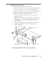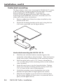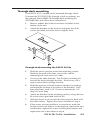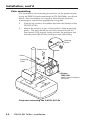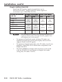
1
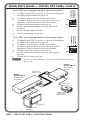
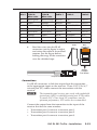
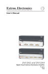
User’s Manual DVI DL 201 Tx/Rx Dual Link DVI Transmitter and Receiver 68-1531-01 Rev. B 12 08 Precautions Safety Instructions • English This symbol is intended to alert the user of important operating and maintenance (servicing) instructions in the literature provided with the equipment. This symbol is intended to alert the user of the presence of uninsulated dangerous voltage within the product’s enclosure that may present a risk of electric shock. Caution Read Instructions • Read and understand all safety and operating instructions before using the equipment. Retain Instructions • The safety instructions should be kept for future reference. Follow Warnings • Follow all warnings and instructions marked on the equipment or in the user information. Avoid Attachments • Do not use tools or attachments that are not recommended by the equipment manufacturer because they may be hazardous. Consignes de Sécurité • Français Ce symbole sert à avertir l’utilisateur que la documentation fournie avec le matériel contient des instructions importantes concernant l’exploitation et la maintenance (réparation). Ce symbole sert à avertir l’utilisateur de la présence dans le boîtier de l’appareil de tensions dangereuses non isolées posant des risques d’électrocution. Attention Lire les instructions• Prendre connaissance de toutes les consignes de sécurité et d’exploitation avant d’utiliser le matériel. Conserver les instructions• Ranger les consignes de sécurité afin de pouvoir les consulter à l’avenir. Respecter les avertissements • Observer tous les avertissements et consignes marqués sur le matériel ou présentés dans la documentation utilisateur. Eviter les pièces de fixation • Ne pas utiliser de pièces de fixation ni d’outils non recommandés par le fabricant du matériel car cela risquerait de poser certains dangers. Sicherheitsanleitungen • Deutsch Dieses Symbol soll dem Benutzer in der im Lieferumfang enthaltenen Dokumentation besonders wichtige Hinweise zur Bedienung und Wartung (Instandhaltung) geben. Dieses Symbol soll den Benutzer darauf aufmerksam machen, daß im Inneren des Gehäuses dieses Produktes gefährliche Spannungen, die nicht isoliert sind und die einen elektrischen Schock verursachen können, herrschen. Achtung Lesen der Anleitungen • Bevor Sie das Gerät zum ersten Mal verwenden, sollten Sie alle Sicherheits-und Bedienungsanleitungen genau durchlesen und verstehen. Aufbewahren der Anleitungen • Die Hinweise zur elektrischen Sicherheit des Produktes sollten Sie aufbewahren, damit Sie im Bedarfsfall darauf zurückgreifen können. Befolgen der Warnhinweise • Befolgen Sie alle Warnhinweise und Anleitungen auf dem Gerät oder in der Benutzerdokumentation. Keine Zusatzgeräte • Verwenden Sie keine Werkzeuge oder Zusatzgeräte, die nicht ausdrücklich vom Hersteller empfohlen wurden, da diese eine Gefahrenquelle darstellen können. Instrucciones de seguridad • Español Este símbolo se utiliza para advertir al usuario sobre instrucciones importantes de operación y mantenimiento (o cambio de partes) que se desean destacar en el contenido de la documentación suministrada con los equipos. Este símbolo se utiliza para advertir al usuario sobre la presencia de elementos con voltaje peligroso sin protección aislante, que puedan encontrarse dentro de la caja o alojamiento del producto, y que puedan representar riesgo de electrocución. Precaucion Leer las instrucciones • Leer y analizar todas las instrucciones de operación y seguridad, antes de usar el equipo. Conservar las instrucciones • Conservar las instrucciones de seguridad para futura consulta. Obedecer las advertencias • Todas las advertencias e instrucciones marcadas en el equipo o en la documentación del usuario, deben ser obedecidas. Evitar el uso de accesorios • No usar herramientas o accesorios que no sean especificamente recomendados por el fabricante, ya que podrian implicar riesgos. Warning Power sources • This equipment should be operated only from the power source indicated on the product. This equipment is intended to be used with a main power system with a grounded (neutral) conductor. The third (grounding) pin is a safety feature, do not attempt to bypass or disable it. Power disconnection • To remove power from the equipment safely, remove all power cords from the rear of the equipment, or the desktop power module (if detachable), or from the power source receptacle (wall plug). Power cord protection • Power cords should be routed so that they are not likely to be stepped on or pinched by items placed upon or against them. Servicing • Refer all servicing to qualified service personnel. There are no userserviceable parts inside. To prevent the risk of shock, do not attempt to service this equipment yourself because opening or removing covers may expose you to dangerous voltage or other hazards. Slots and openings • If the equipment has slots or holes in the enclosure, these are provided to prevent overheating of sensitive components inside. These openings must never be blocked by other objects. Lithium battery • There is a danger of explosion if battery is incorrectly replaced. Replace it only with the same or equivalent type recommended by the manufacturer. Dispose of used batteries according to the manufacturer’s instructions. Avertissement Alimentations• Ne faire fonctionner ce matériel qu’avec la source d’alimentation indiquée sur l’appareil. Ce matériel doit être utilisé avec une alimentation principale comportant un fil de terre (neutre). Le troisième contact (de mise à la terre) constitue un dispositif de sécurité : n’essayez pas de la contourner ni de la désactiver. Déconnexion de l’alimentation• Pour mettre le matériel hors tension sans danger, déconnectez tous les cordons d’alimentation de l’arrière de l’appareil ou du module d’alimentation de bureau (s’il est amovible) ou encore de la prise secteur. Protection du cordon d’alimentation • Acheminer les cordons d’alimentation de manière à ce que personne ne risque de marcher dessus et à ce qu’ils ne soient pas écrasés ou pincés par des objets. Réparation-maintenance • Faire exécuter toutes les interventions de réparationmaintenance par un technicien qualifié. Aucun des éléments internes ne peut être réparé par l’utilisateur. Afin d’éviter tout danger d’électrocution, l’utilisateur ne doit pas essayer de procéder lui-même à ces opérations car l’ouverture ou le retrait des couvercles risquent de l’exposer à de hautes tensions et autres dangers. Fentes et orifices • Si le boîtier de l’appareil comporte des fentes ou des orifices, ceux-ci servent à empêcher les composants internes sensibles de surchauffer. Ces ouvertures ne doivent jamais être bloquées par des objets. Lithium Batterie • Il a danger d’explosion s’ll y a remplacment incorrect de la batterie. Remplacer uniquement avec une batterie du meme type ou d’un ype equivalent recommande par le constructeur. Mettre au reut les batteries usagees conformement aux instructions du fabricant. Vorsicht Stromquellen • Dieses Gerät sollte nur über die auf dem Produkt angegebene Stromquelle betrieben werden. Dieses Gerät wurde für eine Verwendung mit einer Hauptstromleitung mit einem geerdeten (neutralen) Leiter konzipiert. Der dritte Kontakt ist für einen Erdanschluß, und stellt eine Sicherheitsfunktion dar. Diese sollte nicht umgangen oder außer Betrieb gesetzt werden. Stromunterbrechung • Um das Gerät auf sichere Weise vom Netz zu trennen, sollten Sie alle Netzkabel aus der Rückseite des Gerätes, aus der externen Stomversorgung (falls dies möglich ist) oder aus der Wandsteckdose ziehen. Schutz des Netzkabels • Netzkabel sollten stets so verlegt werden, daß sie nicht im Weg liegen und niemand darauf treten kann oder Objekte darauf- oder unmittelbar dagegengestellt werden können. Wartung • Alle Wartungsmaßnahmen sollten nur von qualifiziertem Servicepersonal durchgeführt werden. Die internen Komponenten des Gerätes sind wartungsfrei. Zur Vermeidung eines elektrischen Schocks versuchen Sie in keinem Fall, dieses Gerät selbst öffnen, da beim Entfernen der Abdeckungen die Gefahr eines elektrischen Schlags und/oder andere Gefahren bestehen. Schlitze und Öffnungen • Wenn das Gerät Schlitze oder Löcher im Gehäuse aufweist, dienen diese zur Vermeidung einer Überhitzung der empfindlichen Teile im Inneren. Diese Öffnungen dürfen niemals von anderen Objekten blockiert werden. Litium-Batterie • Explosionsgefahr, falls die Batterie nicht richtig ersetzt wird. Ersetzen Sie verbrauchte Batterien nur durch den gleichen oder einen vergleichbaren Batterietyp, der auch vom Hersteller empfohlen wird. Entsorgen Sie verbrauchte Batterien bitte gemäß den Herstelleranweisungen. Advertencia Alimentación eléctrica • Este equipo debe conectarse únicamente a la fuente/tipo de alimentación eléctrica indicada en el mismo. La alimentación eléctrica de este equipo debe provenir de un sistema de distribución general con conductor neutro a tierra. La tercera pata (puesta a tierra) es una medida de seguridad, no puentearia ni eliminaria. Desconexión de alimentación eléctrica • Para desconectar con seguridad la acometida de alimentación eléctrica al equipo, desenchufar todos los cables de alimentación en el panel trasero del equipo, o desenchufar el módulo de alimentación (si fuera independiente), o desenchufar el cable del receptáculo de la pared. Protección del cables de alimentación • Los cables de alimentación eléctrica se deben instalar en lugares donde no sean pisados ni apretados por objetos que se puedan apoyar sobre ellos. Reparaciones/mantenimiento • Solicitar siempre los servicios técnicos de personal calificado. En el interior no hay partes a las que el usuario deba acceder. Para evitar riesgo de electrocución, no intentar personalmente la reparación/mantenimiento de este equipo, ya que al abrir o extraer las tapas puede quedar expuesto a voltajes peligrosos u otros riesgos. Ranuras y aberturas • Si el equipo posee ranuras o orificios en su caja/alojamiento, es para evitar el sobrecalientamiento de componentes internos sensibles. Estas aberturas nunca se deben obstruir con otros objetos. Batería de litio • Existe riesgo de explosión si esta batería se coloca en la posición incorrecta. Cambiar esta batería únicamente con el mismo tipo (o su equivalente) recomendado por el fabricante. Desachar las baterías usadas siguiendo las instrucciones del fabricante. 安全须知 • 中文 警告 这个符号提示用户该设备用户手册中 有重要的操作和维护说明。 电源 • 该 设 备 只 能 使 用 产 品 上 标 明 的 电 源 。 设 备 必须使用有地线的供电系统供电。 第三条线 (地线)是安全设施,不能不用或跳过。 这个符号警告用户该设备机壳内有暴 拔掉电源 • 为安全地从设备拔掉电源,请拔掉所有设备后 或桌面电源的电源线,或任何接到市电系统的电源线。 露的危险电压,有触电危险。 电源线保护 • 妥善布线, 避免被踩踏,或重物挤压。 注意 阅读说明书 • 用 户 使 用 该 设 备 前 必 须 阅 读 并 理 解所有安全和使用说明。 保存说明书 • 用户应保存安全说明书以备将来使 用。 遵守警告 • 用户应遵守产品和用户指南上的所有安 全和操作说明。 维护 • 所有维修必须由认证的维修人员进行。 设备内部 没有用户可以更换的零件。为避免出现触电危险不要自 己试图打开设备盖子维修该设备。 通风孔 • 有些设备机壳上有通风槽或孔,它们是用来防止 机内敏感元件过热。 不要用任何东西挡住通风孔。 锂电池 • 不正确的更换电池会有爆炸的危险。 必须使用 与厂家推荐的相同或相近型号的电池。 按照生产厂的 建议处理废弃电池。 避免追加 • 不要使用该产品厂商没有推荐的工具或 追加设备,以避免危险。 声明 所使用电源为 A 级产品,在生活环境中,该产品可能会造成无线电干扰。在这种情况下,可能需要用 户对其干扰采取切实可行的措施。 FCC Class A Notice This equipment has been tested and found to comply with the limits for a Class A digital device, pursuant to part 15 of the FCC Rules. Operation is subject to the following two conditions: (1) this device may not cause harmful interference, and (2) this device must accept any interference received, including interference that may cause undesired operation. The Class A limits are designed to provide reasonable protection against harmful interference when the equipment is operated in a commercial environment. This equipment generates, uses, and can radiate radio frequency energy and, if not installed and used in accordance with the instruction manual, may cause harmful interference to radio communications. Operation of this equipment in a residential area is likely to cause harmful interference, in which case the user will be required to correct the interference at his own expense. N This unit was tested with shielded cables on the peripheral devices. Shielded cables must be used with the unit to ensure compliance with FCC emissions limits. Quick Start Guide — DVI DL 201 Tx/Rx The DVI DL 201 Tx/Rx extends DVI-D signals up to 100' (30 m) at resolutions up to 2560x1600 @ 60 Hz, using twisted pair (TP) cable. Install, connect, and operate the DVI DL 201 Tx/Rx as follows: Step 1 Turn off all equipment or disconnect it from power sources. Mount the transmitter and receiver as desired (see page 2-2). Step 2 To capture the EDID of a desired display and store it in the EDID Minder for future use: b. c. d. e. f. g. h. i. j. Connect the display to the local monitor output of the transmitter. Power on the transmitter and the local monitor. ON ON Configure the DDC switches as shown in the figure at right and described on page 3-2. 1 2 3 OFF Press and release the EDID "Store" button (see the figure at right). The rear panel LED turns EDID amber while the EDID information is read and STORE stored from the local monitor. Afterwards, the LED turns green. Power off and disconnect the display from the transmitter. Connect the transmitter to the receiver. Connect a source device to the transmitter. Connect a display device to the receiver and, if required, a local monitor to the transmitter. Power on the display device(s), the transmitter, and the receiver. Power on the source device. To use the default EDID (2560x1600 @ 60 Hz): a. b. c. d. e. f. Configure the DDC switches as shown in the figure at right and described on page 3-3. ON Connect a source device to the transmitter. Connect a display device to the receiver and, if OFF required, a local monitor to the transmitter. Connect the transmitter and receiver. Power on the transmitter, receiver, and display devices. Power on the source device. DVI DL 201 Tx/Rx • Quick Start Guide EDID MINDER DEFAULT EDID REMOTE DDC a. EDID MINDER DEFAULT EDID REMOTE DDC Determine how the source device will obtain the EDID information and perform one of the following procedures: ON 1 2 3 QS-1 Quick Start Guide — DVI DL 201 Tx/Rx, cont’d a. b. c. d. e. f. g. EDID MINDER DEFAULT EDID REMOTE DDC To use DDC pass-through routed to the local monitor: Configure the DDC switches as shown in the figure at right and described on page 3-4. Connect a source device to the transmitter. Connect a display device to the receiver and, if required, a local monitor to the transmitter. Connect the transmitter and receiver. Power on the transmitter, receiver, and local monitor. Power on the source device. Power on the display device. ON ON OFF a. b. c. d. e. f. EDID MINDER DEFAULT EDID REMOTE DDC To use DDC pass-through routed to the remote display: 1 2 3 Configure the DDC switches as shown in the figure at right and described on page 3-5. Connect a source device to the transmitter. Connect a display device to the receiver and, if required, a local monitor to the transmitter. Connect the transmitter and receiver. Power on the transmitter, receiver, and display devices. Power on the source device. ON ON OFF 1 2 3 If there are any problems, consult the troubleshooting section (page 3-6). N Extron DVI DL 201 Rx DVI Dual Link Receiver Twisted Pair Cables (3) 100’ Extron DVI DL 201 Tx L RO 2 NT RU -23 RU CO TH RS TH SS SS PA Rx PA Tx Rx Sx Tx R 1IER 20 Lx SE I1DR T T U UTP OU UTP O-D -D DVI DVI DVI V 20 DLD DVI Dual Link Transmitter UT TP OU 3 2 1 UT TP UT UTP OU DVI Dual Link T NO T DO EC NN S CO TPUT N OU LA TO O AL C LO T I-D INPU DV UT WER PO V 12 MAX A 0.4 C DD RO E TE MO RE 2 -23 RS -THRU SS PA L CA LO High Resolution Projector with Dual Link Input E AR SP Local Monitor PC with Dual Link DVI Output QS-2 DVI DL 201 Tx/Rx • Quick Start Guide Table of Contents Chapter One • Introduction..................................................... 1-1 About this Manual..................................................................... 1-2 About the DVI DL 201 Tx/Rx................................................... 1-2 DVI DL 201 Tx/Rx Features...................................................... 1-2 Chapter Two • Installation....................................................... 2-1 Mounting the DVI DL 201 Tx/Rx. .......................................... 2-2 Tabletop placement................................................................ 2-2 Rack mounting........................................................................ 2-2 UL guidelines for rack mounting............................................2-2 Rack mounting procedures.....................................................2-3 Under-desk mounting............................................................. 2-4 Through-desk mounting......................................................... 2-5 Pole mounting......................................................................... 2-6 Panel Features............................................................................. 2-8 DVI DL 201 Tx front panel features....................................... 2-8 DVI DL 201 Tx rear panel features......................................... 2-9 DVI DL 201 Rx front panel features..................................... 2-10 DVI DL 201 Rx rear panel features....................................... 2-11 Cable Connections and Switches........................................ 2-12 DVI-D input............................................................................ 2-12 DVI-D output......................................................................... 2-12 Twisted pair output/input.................................................... 2-14 Terminating shielded cable...................................................2-14 Connections...........................................................................2-15 Single Link/Dual Link DVI.....................................................2-16 DDC switches......................................................................... 2-17 Control pass-through............................................................ 2-18 RS-232 signals........................................................................2-19 IR signals................................................................................2-19 Power input........................................................................... 2-20 DVI DL 201 Tx/Rx • Table of Contents i Table of Contents, cont’d Chapter Three • Configuration and Operation. ........ 3-1 Configuration.............................................................................. 3-2 Using the EDID Minder to read and store EDID from a display..................................................................................... 3-2 Using the EDID Minder with the default EDID..................... 3-3 Using pass-through mode with DDC routed to a local monitor.................................................................................... 3-4 Using pass-through mode with DDC routed to the remote display..................................................................................... 3-5 Setup. ............................................................................................. 3-6 Troubleshooting.......................................................................... 3-6 Appendix A • Reference Information .............................A-1 Specifications...............................................................................A-2 Included Parts..............................................................................A-5 Optional Accessories.................................................................A-5 All trademarks mentioned in this manual are the properties of their respective owners. 68-1531-01 Rev. B 12 08 ii DVI DL 201 Tx/Rx • Table of Contents DVI DL 201 Tx/Rx 1 Chapter One Introduction About this Manual About the DVI DL 201 Tx/Rx DVI DL 201 Tx/Rx Features Introduction About this Manual This manual contains information about the DVI DL 201 Tx/Rx signal transmitter and receiver, with information on how to mount, install, and operate these units. In this manual, unless otherwise specified, the terms "DVI DL 201" or "DVI DL 201 Tx/Rx" refer to both the transmitter (DVI DL 201 Tx) and the receiver (DVI DL 201 Rx). The term "transmitter" refers to the DVI DL 201 Tx, and "receiver" refers to the DVI DL 201 Rx. About the DVI DL 201 Tx/Rx The DVI DL 201 Tx and DVI DL 201 Rx are dual link DVI transmitter/receiver units. They can be purchased as a pair or as individual units. Each purchased pair and each individual unit is shipped with a single external desktop 12 VDC power supply. A single power supply, connected to the transmitter, is able to power both devices. Using three CAT 5/5e/6/7 twisted pair cables, DVI-D signals can be extended up to 100' (30 m) at resolutions up to 2560 x 1600 @ 60 Hz. This is significantly further than the 15' (5 m) specified for standard dual link DVI cables. N The DVI DL 201 Tx/Rx works with unshielded twisted pair (UTP) cable or shielded twisted pair (STP) cable. However, STP cables are required to ensure FCC Class A and CE compliance. DVI DL 201 Tx/Rx Features Transmits dual link DVI-D signals over three CAT 5/5e/6/7 cables — Standard twisted pair cables provide an economical, easily installed cable solution. Long distance transmission — Signals are transmitted up to 100' (30 m), which is significantly further than the 15' (5 m) specified for standard dual link DVI cables. Local monitor output — The transmitter has a DVI-D output for connection to a local monitor. DDC routing to local or remote display — A two pole switch allows the user to determine whether DDC signals are routed to the local or the remote display device. 1-2 DVI DL 201 Tx/Rx • Introduction EDID Minder — The EDID Minder maintains continuous EDID (Extended Display Identification Data) communication with the attached source. This ensures that the DVI source powers up correctly and maintains a proper video output, even if the display is off. Control communications pass-through — The DVI DL 201 passes through RS-232 (two way) or IR (one way) control signals, to a remote display. Compact design — The transmitter is 1U high, a half rack wide and 3" deep, for easy rack mounting near the source device. The receiver is 1" high, a quarter rack wide and 3" deep, allowing multiple mounting options near the display device. Remote powering of receiver — A single power supply, connected to the transmitter, is able to power both the transmitter and receiver. Extron DVI DL 201 Tx Dual Link DVI Transmitter CAT 5/5e/6/7 Cables up to 200 feet 3 2 1 UT TP UT TP L OU OU T NO T DO EC NN TS CO TPU OU LAN TO CA LO I-D T INPU DV R WE PO V 12 MAX A 0.4 2 -23 U RS HR S-T UTE C RO TE MO RE PAS DD L CA LO RE SPA RS-232 Local Monitor Control System PC w/ Dual Link DVI Output L RO NT RU CO TH SS PA Rx Tx x 1R T Extron DVI DL 201 Rx Dual Link DVI Receiver PU I-D OUT L 20 ID DV RS-232 DV Dual Link DVI Cable 2560 x 1600 Flat Panel Display with Dual-Link DVI Input Typical Application for the DVI DL 201 Tx/Rx DVI DL 201 Tx/Rx • Introduction 1-3 Introduction, cont’d 1-4 DVI DL 201 Tx/Rx • Introduction DVI DL 201 Tx/Rx 2 Chapter Two Installation Mounting the DVI DL 201 Tx/Rx Panel Features Cable Connections and Switches Installation Mounting the DVI DL 201 Tx/Rx The transmitter is 1U high, a half rack wide and 3" deep, for easy rack mounting near the source device. The receiver is 1" high, a quarter rack wide and 3" deep, allowing multiple mounting options near the display device. Tabletop placement Attach the four included rubber feet to the bottom of the unit and place it in any convenient location. Rack mounting UL guidelines for rack mounting The following Underwriters Laboratories (UL) guidelines are relevant to the safe installation of the DVI DL 201 Tx/Rx in a rack: 2-2 1. Elevated operating ambient temperature — If the unit is installed in a closed or multi-unit rack assembly, the operating ambient temperature of the rack environment may be greater than room ambient temperature. Therefore, install the equipment in an environment compatible with the maximum ambient temperature (Tma: +122 °F, +50 °C) specified by Extron. 2. Reduced air flow — Install the equipment in the rack so that the equipment gets adequate air flow for safe operation. 3. Mechanical loading — Mount the equipment in the rack so that uneven mechanical loading does not create a hazardous condition. 4. Circuit overloading — Connect the equipment to the supply circuit and consider the effect that circuit overloading might have on overcurrent protection and supply wiring. Give appropriate consideration to the equipment nameplate ratings when addressing this concern. 5. Reliable earthing (grounding) — Maintain reliable grounding of rack-mounted equipment. Pay particular attention to supply connections other than direct connections to the branch circuit (such as the use of power strips). DVI DL 201 Tx/Rx • Installation Rack mounting procedures The unit can be mounted in the front or rear of: • RSU 126 (6" deep 1U universal rack shelf kit: PN 60-190-10) • RSB 126 (6" deep 1U basic rack shelf: PN 60-604-10) • RSU 129 (9.5" deep 1U universal rack shelf kit: PN 60-190-01) • RSB 129 (9.5" deep 1U basic rack shelf: PN 60-604-01) To mount the unit, follow these instructions: 1. Remove rubber feet if these have been installed on the bottom of the unit. 2. Align the unit on the shelf and secure it to the shelf with two 4-40 x 3/16" screws in diagonally opposite corners (see the figure below, which shows installation using the RSU 129 shelf). 3. Install false faceplate(s) or other unit(s) to the rack shelf. 4. Attach the shelf to the rack with the four provided 10-32 x 3/4" bolts HalfRackVersaToolsStandardShelf 1U Universal Rack Shelf 1/2 Rack Width Front False Faceplate Front false faceplate uses 2 screws. Use 2 mounting holes on opposite corners. (2) 4-40 x 3/16" Screws Installing the DVI DL 201 Tx on a rack shelf DVI DL 201 Tx/Rx • Installation 2-3 Installation, cont’d Under-desk mounting The figure below shows how to mount the DVI DL 201 Tx under a desk or podium, using the optional Extron MBU 123 under desk mounting kit (PN 70-212-01). To mount the DVI DL 201 Rx, the optional Extron MBU 125 under desk mounting kit (PN 70-077-01, not shown) must be used. For either unit, follow these instructions: 1. Remove rubber feet if these have been installed on the bottom of the unit. 2. Secure the mounting brackets to the unit, using the four 4-40 screws provided (see the figure below). Under-desk mounting the DVI DL 201 Tx 2-4 3. Hold the unit with the brackets attached against the underside of the table or other furniture. Mark the location of the screw holes of the bracket on the mounting surface. 4. Drill four pilot holes, each 3/32" (2 mm) in diameter by 1/4" (6.3 mm) deep in the mounting surface at the marked screw locations. 5. Insert #8 wood screws into the four pilot holes. Tighten each screw into the mounting surface until just less than 1/4" (6.3 mm) of the screw head protrudes. 6. Guide the mounting screws through the slots in the brackets and place the unit tight against the surface. 7. Slide the unit slightly in or out so that it is held in place by the screws; tighten all four screws to secure the unit in place (see the figure above). DVI DL 201 Tx/Rx • Installation Through-desk mounting The DVI DL 201 Tx should not be mounted through a desk. To mount the DVI DL 201 Rx through a desk or podium, use the optional Extron MBD 129 through-desk mounting kit (PN 70‑077‑02), and follow these instructions: 1. Remove rubber feet if these have been installed on the bottom of the unit. 2. Attach the brackets to the receiver, using the four 4-40 screws provided; leave the screws slightly loose. Through-desk mounting the DVI DL 201 Rx 3. Hold the unit in position under the mounting surface. Mark the location of the four screw holes and the mounting hole to be cut in the table. 4. Cut away the table material. Test the fit by inserting the front of the device through the hole. If necessary, use a rasp or coarse file to enlarge the hole. 5. Hold the receiver, with the brackets attached, in position and mark the location of the holes in the brackets. Drill four pilot holes, each 3/32" (2 mm) in diameter by 1/4" deep (6.3 mm) deep. 6. Attach the brackets to the mounting surface, using the four #8 wood screws provided with the kit. 7. Slide the device in or out until the front panel is flush with the table surface. Tighten the screws installed in step 2. 8. If the screws are inaccessible to a screwdriver, mark the location of the unit relative to the brackets, remove the unit and brackets, tighten the screws holding the brackets and replace the unit as described in step 6. DVI DL 201 Tx/Rx • Installation 2-5 Installation, cont’d Pole mounting The instructions for mounting the receiver on the projector pole, using the PMK 300 pole mounting kit (PN 70-374-01), are shown below. For instructions on using any other Extron projector mounting kit, consult the appropriate user guide. 1. If necessary, remove the rubber feet from the bottom of the DVI DL 201 Rx. 2. Mount the receiver to any of the bracket's three mounting plates. The unit should be vertically mounted with the front panel (DVI output) facing towards the projector and the rear panel (RJ-45 slots) facing towards the ceiling. Backing Brace Rubber Pad U-Bolt Clamping Plate Extron PMK 300 Multi Product Projector Mount Kit Projector mounting the DVI DL 201 Rx 2-6 DVI DL 201 Tx/Rx • Installation N On the side mounting plates, the device is typically mounted on the outside of the bracket. On the front mounting plate, the device is mounted on the inside of the bracket. a. Use the two 4-40 x 3/16" screws (provided) to secure the receiver to the bracket b. If required, secure the power supply using the plastic ties provided with the kit. N The projector pole can be clamped to the back surface of the clamping plate on the PMK 300, as shown in the figure on the previous page. Alternatively, the PMK 300 has a hole in the bottom plate that allows the projector pole to be inserted through the center of the plate. In this configuration, slide the PMK 300 up from the bottom of the pole before the projector is installed. 3. Attach the rubber pad to the surface of the clamping plate that will be in contact with the pole. 4. Place the U-bolt around the projector pole and insert the two ends through the slotted holes in the clamping plate and then through the round holes in the backing brace. N 5. The provided U-bolt fits a pole with an external diameter of 1.5" to 2.0". For larger or smaller diameter poles, obtain a U-bolt from a local hardware store. The slotted holes in the clamping plate can accommodate U-bolts that are 1.0" to 2.5" in width. Secure the bracket to the projector pole with the U-bolt and the provided hex nuts and washers. Use an appropriatelysized socket wrench to tighten the hex nuts. DVI DL 201 Tx/Rx • Installation 2-7 Installation, cont’d Panel Features DVI DL 201 Tx front panel features The illustration below shows the front panel features of the DVI DL 201 Tx. DVI DL 201 Tx DVI DUAL LINK TRANSMITTER 1 DVI DL 201 Tx front panel features a 2-8 LED — An amber light indicates that the DVI DL 201 Tx is receiving power from a power supply or remotely, through the receiver. A green light indicates that the transmitter is also receiving a video signal. DVI DL 201 Tx/Rx • Installation DVI DL 201 Tx rear panel features DVI DL 201 Tx POWER 12V 0.4A MAX EDID MINDER DEFAULT EDID REMOTE DDC The illustration below shows the rear panel features of the DVI DL 201 Tx. SN XXXXXXXX E XXXXX 00/00 DVI DL TX DVI-D INPUT LOCAL OUTPUT EDID STORE ON ON OFF 2 3 4 5 DO NOT CONNECT OUTPUTS TO LAN CONTROL PASS THRU 1 OUTPUTS 2 3 Tx Rx 1 2 3 6 7 8 DVI DL 201 Tx rear panel features b c d e f g h Power input — The 12 VDC power supply (provided) connects to this two-pole, 3.5 mm captive screw connector. DVI-D input — One female DVI-I connector accepts a dual-link DVI-D input from the source device. Local monitor output — One female DVI-I connector provides a dual-link DVI-D output to the local monitor. EDID Minder Store switch and LED — When depressed, the transmitter reads and stores the EDID information from the local monitor. The LED gives the status of this process. DDC route switches — Three DIP switches allow the unit to be configured to use the EDID Minder or route the DDC directly to the display. Control signal pass-through — A three-pole, 3.5 mm captive screw connector inputs pass-through RS-232 (two-way) or IR signals (one-way). Twisted pair outputs — Three RJ-45 jacks are used for transmitting DVI video, remote power, and communications/ control signals. N The DVI DL 201 transmits high frequency signals via these TP outputs. Connections between the transmitter and receiver must be point to point. It is recommended that there should be no couplers, adapter, or patch panels between the transmitter and receiver units. DVI DL 201 Tx/Rx • Installation 2-9 Installation, cont’d DVI DL 201 Rx front panel features The illustration below shows the front panel features of the DVI DL 201 Rx. DVI-D OUTPUT CONTROL PASS THRU Tx Rx DVI 201 Rx SERIES 9 10 11 DVI DL 201 Rx front panel features i j k 2-10 Power LED — An amber light indicates that the DVI DL 201 Rx is receiving power from a power supply or remotely, through the transmitter. A green light indicates that the receiver is also receiving a video signal. DVI-D output — One female DVI-I connector provides a dual-link DVI-D output. Control signal pass-through — A three-pole, 3.5 mm captive screw connector inputs pass-through RS-232 (two-way) or IR signals (one-way). DVI DL 201 Tx/Rx • Installation DVI DL 201 Rx rear panel features The illustration below shows the rear panel features of the DVI DL 201 Rx. 1 INPUTS 2 3 DO NOT CONNECT INPUTS TO LAN 12 DVI DL 201 Rx POWER 12V 0.4A MAX 13 DVI DL 201 Rx rear panel features l Power input — An optional 12 VDC power supply (not provided) connects to this two-pole, 3.5 mm captive screw connector. N m The receiver can be remotely powered by the transmitter. Twisted pair inputs — Three RJ-45 jacks receive video, remote power, and pass-through communications/control signals from the transmitter. They can also send pass-through control signals via the transmitter. N The DVI DL 201 transmits high frequency signals via these TP outputs. Connections between the transmitter and receiver must be point to point. It is recommended that there should be no couplers, adapter, or patch panels between the transmitter and receiver units. DVI DL 201 Tx/Rx • Installation 2-11 Installation, cont’d Cable Connections and Switches DVI-D input Connect the DVI-D source device to the female DVI-I input connector. The dual link DVI-D input carries a signal with a resolution up to 2560x1600 @ 60 Hz. For sources providing HDMI signals, use an HDMI to DVI adapter, such as the Extron HDMIF-DVIDM female HDMI to male DVI-D adapter (PN 26-616-01). The pin assignments for the DVI-I input connectors are shown in the table on the next page. DVI-D output Connect the local display device to the female DVI-I output connector on the rear panel of the transmitter and the remote display device to the output connector on the front panel of the receiver. The dual link DVI-D output carries a signal with a resolution up to 2560x1600 @ 60 Hz. The pin assignments for the DVI-I output connectors are the same as those for the input connectors and are shown in the table on the next page. N 2-12 Although DVI-I connectors are used, the DVI DL 201 is compatible only with DVI-D signals. DVI DL 201 Tx/Rx • Installation DVI Dual Link - Female 1 8 17 24 9 Pin Signal Pin Signal Pin Signal 1 TMDS data 2– 9 TMDS data 1– 17 TMDS data 0– 2 TMDS data 2+ 10 TMDS data 1+ 18 TMDS data 0+ 3 TMDS data 2/4 shield 11 TMDS data 1/3 shield 19 TMDS data 0/5 shield 4 TMDS data 4- 12 TMDS data 3- 20 TMDS data 5- 5 TMDS data 4+ 13 TMDS data 3+ 21 TMDS data 5+ 6 DDC clock 14 +5 V power 22 TMDS clock shield 7 DDC data 15 Ground 23 TMDS clock+ 8 CEC control* 16 Hot plug detect 24 TMDS clock– *CEC control on pin 8 is a proprietary usage and is not the industry standard DVI DL 201 Tx/Rx • Installation 2-13 Installation, cont’d Twisted pair output/input Terminating shielded cable CAT 5/5e/6/7 twisted pair cable is not provided with the transmitter/receiver pair. You may purchase cables that have been precut to the required length and terminated to the T586A or T586B standard (see the table on the next page). Alternatively, purchase bulk cable and use the RJ-45 connectors (provided) to prepare your own terminated cables as described below. N The transmitter and receiver pair works with unshielded twisted pair (UTP) or shielded twisted pair (STP) cables. To ensure FCC Class A and CE compliance, and for optimum performance, STP cables are recommended. N Do not use Extron Skew Free Cable with this product. 1. Cut the cables to the required length. All three cables should be the same length. 2. Remove about 7/8" (2.2 cm) of the outer coat. If using STP cable, peel back the shielding and fold it over the top of the outer coat. Peel back shield and fold back. 3. Cut away and discard the clear cellophane inner wrapper that extends beyond the folded back shielding. 4. Cut a piece of self-adhesive shielded aluminum tape (provided), remove the backing, and wrap it around the folded back shielding. Aluminum Tape 5. 2-14 Wrap tape around folded foil shielding. Slightly overlap. Cut and save the excess tape for other connectors. Separate the individual wires, and arrange them so that all eight wires are side by side in the same order as the T586A or T586B standard shown at the top of the next page. Both ends of a cable must be wired to the same standard (T586A or T586B). DVI DL 201 Tx/Rx • Installation Pin # TIA/EIA T 586 A Wire color TIA/EIA T 586 B Wire color Cable 1 Cable 2 Cable 3 1 White-green White-orange Data 0+ CEC Data 3+ 2 Green Orange Data 0+ HPD Data 3+ 3 White-orange White-green IDCK+ RS-232 Tx/IR+ N/C 4 Blue Blue Data 1+ DDC Clock Data 4+ 5 White-blue White-blue Data 1+ +12 V Data 4+ 6 Orange Green IDCK- RS-232 Rx N/C 7 White-brown White-brown Data 2+ 8 Brown Brown Data 2+ DDC Data Data 5+ RJ-45 Ground Connector Data 5+ 6. Feed the wires into the RJ-45 connector (see the figure at right) and crimp the cable in the normal manner (see the figure below), folding the tangs of the connector over the shielded tape. Side Pins: 12345678 Insert Twisted Pair Wires Crimped Connector Connections Use RJ-45 connectors to link the output from the transmitter to the appropriate input on the receiver. Three CAT 5/5e/6/7 twisted pair (TP) cables connect the transmitter with the receiver. N The transmitter and receiver pair works with unshielded twisted pair (UTP) or shielded twisted pair (STP) cables. To ensure FCC Class A and CE compliance, and for optimum performance, STP cables are recommended. Connect the output from the transmitter to the input of the receiver that has the same number: • Transmitter port 1 connects to receiver port 1. • Transmitter port 2 connects to receiver port 2. • Transmitter port 3 connects to receiver port 3. DVI DL 201 Tx/Rx • Installation 2-15 Installation, cont’d Single Link/Dual Link DVI Dual Link DVI carries signals at resolutions up to 2560x1600 @ 60 Hz. Single Link DVI carries signals at resolutions up to 1920x1200 @ 60 Hz. Video Resolution (60 Hz) 1024x768 720p 1080i 1920x1200 1600x1200 1080p 2560x1600 N 2-16 Single Link Mode Dual Link Mode UTP UTP STP STP 200' (60 m) 200' (60 m) 200' (60 m) 200' (60 m) 100' (30 m) 125' (38 m) 200' (60 m) 200' (60 m) N/A N/A 100' (30 m) 125' (38 m) The transmission distance varies greatly depending on signal resolution and on the type of cable, graphic card, and display used in the system. • To operate in Dual Link mode, all three TP cables are required and both the source and display devices must support Dual Link DVI signals. • To operate in Single Link mode, only TP cables 1 and 2 are required. Dual Link DVI is backwards compatible with Single Link DVI. • The DVI/HDMI 201 (Single Link) receivers can be used with the DVI DL 201 transmitter, in Single Link mode (using only TP cables 1 and 2). DVI DL 201 Tx/Rx • Installation DDC switches When the DVI-D source device boots up, it uses the Display Data Channel (DDC), a two-way communication protocol, to obtain Extended Display Identification Data (EDID) from the display device. This allows the source to output a resolution that matches the capabilities of the display. A bank of three switches allows the user to determine how the source device will obtain the EDID. The EDID can be obtained directly from the display device, or from the internal memory within. The three switches are: Default EDID — When the Default EDID switch is on (factory default; see figure at right), an EDID showing a typical Dual Link DVI display resolution of 2560x1600 @ 60 Hz is passed to the source device. The EDID Minder switch must also be on for the Default EDID switch to function. EDID MINDER DEFAULT EDID REMOTE DDC EDID Minder — This switch must be on for the EDID Minder function to be enabled. The factory default for this switch is the off position. ON ON OFF 1 2 3 Remote DDC — When this switch is off, the DDC is routed to the local monitor. When the switch is on, the DDC is routed to the remote display device. See page 3-2 for more information about configuring these switches to provide the source device with the correct EDID. DVI DL 201 Tx/Rx • Installation 2-17 Installation, cont’d Control pass-through The DVI DL 201 Tx/Rx cannot be controlled by RS-232 or IR controls. However, they are able to pass signals from a control device to a remote device that is controlled by those signals. N Tx Rx The RS-232 and IR communications are via a passive pass-through only; the transmitter and receiver neither generate nor respond to these signals. Use the three-pole, 3.5 mm captive screw connector on the transmitter to input RS‑232 or IR signals from a control device. Use the corresponding connector on the receiver to pass signals to the output display. C 3/16" (5 mm) MAX Tx Rx 3-Pole Captive Screw Connector The ideal length of exposed wire in the stripping process is 3/16" (5 mm). If longer than 3/16", the exposed wires may touch, causing a short circuit. If shorter than 3/16", the wires can be easily pulled out even if tightly fastened. Do not tin the wires. Tinned wire does not hold its shape and comes loose over time. 2-18 DVI DL 201 Tx/Rx • Installation RS-232 signals RS-232 signals are bidirectional — signals pass from the control device and replies return from the remote device. To connect the control device to the transmitter, or the receiver to the remote device, make the following connections, as shown at right: • Tx to Tx • Rx to Rx • (ground) to N CONTROL PASS THRU DVI DL 201 Transmitter or Receiver Tx Rx RS-232 Control or Display Device Tx Rx For information about controlling display devices with RS-232 commands, please refer to the user's manual of that device. IR signals IR signals are one-way (from control device CONTROL PASS THRU to the IR emitter that broadcasts the IR Tx Rx DVI DL 201 signal remotely). There are no responses Transmitter and no requirement for a reverse pathway. or Receiver To connect the control device to the transmitter or the receiver to the IR emitter, make the following connections, as shown at right: • The Signal (S), from the control device to IR Control or IR emitter Tx of the transmitter. S G • The ground (G) of the control device is connected to the ground ( ) of the transmitter. • The Tx of the receiver to the S of the IR emitter. • The ground ( ) of the receiver to the ground (G) of the IR emitter. DVI DL 201 Tx/Rx • Installation 2-19 Installation, cont’d Power input 1. Connect the captive screw connector from the supplied 12 VDC power supply into the power receptacle. Twisted pair cable 2, pin 5 carries a 12 VDC power signal. This remote powering feature allows a single power supply, connected to the transmitter, to power both the transmitter and receiver. C POWER 12V 0.4A MAX Power supply voltage polarity is critical. Incorrect voltage polarity can damage the power supply, the transmitter, and/or the receiver. Identify the ground ( ) lead by the ridges on the side of the cord (see the figure below). Power Receptacle Smooth Ridges A DC Power Cord Captive Screw Connector A SECTION A–A Power Supply Output Cord Ground +12 VDC AC Power Cord External Power Supply (12 VDC, 1 A ) Connecting power to DVI DL 201 Tx/Rx C The ideal length of exposed wire in the stripping process is 3/16" (5 mm). If longer than 3/16", the exposed wires may touch, causing a short circuit. If shorter than 3/16", the wires can be easily pulled out even if tightly fastened. Do not tin the wires. Tinned wire does not hold its shape and comes loose over time. 2-20 2. Connect the AC power cord of the power supply unit to a 110 or 220 VAC electrical source. 3. When the transmitter or receiver is getting power, either directly from the power supply or indirectly through the remote powering feature (receiver), the front panel LED lights amber. DVI DL 201 Tx/Rx • Installation DVI DL 201 Tx/Rx 3 Chapter Three Configuration and Operation Configuration Setup and Operation Troubleshooting Configuration and Operation Configuration Using the EDID Minder to read and store EDID from a display During boot up, the DVI-D source device uses Display Data Channel (DDC) to obtain Extended Display Identification Data (EDID) from the display device. This allows the output signal to match the resolution and refresh rate of the display device. The DVI DL 201 Tx/Rx uses Extron's EDID Minder, which allows the user to store and use EDID from any display device. To use this feature, follow these steps: Disconnect all devices and cables from the transmitter and receiver. 2. Connect the desired display to the transmitter's Local Monitor output. For best results, the cable for this connection should be 15' (4.5 m) or shorter. 3. Apply power to the transmitter and the display device. If necessary, connect the power supply to the transmitter. 4. Set the EDID Minder switch on the transmitter to the on (up) position (see the figure at right). 5. Set the Default EDID switch to the off (down) position (see the figure at right). 6. Set the Remote DDC to the off (down) position to allow DDC routing to go to the local monitor (see the figure at right). N 7. EDID MINDER DEFAULT EDID REMOTE DDC 1. ON ON 1 2 3 OFF The EDID Minder extracts information only from the local monitor, not from the remote display. Press and release the EDID Minder Store button. The LED next to the switch turns from green to amber. This indicates that the transmitter is reading and extracting the EDID from the display connected to the local monitor output. EDID STORE When the information has been successfully extracted and stored in non-volatile memory, the LED returns to green. 8. Turn off the display and disconnect it from the transmitter. 9. Connect the transmitter to the receiver with the three twisted pair cables. • Transmitter port 1 connects to receiver port 1. • Transmitter port 2 connects to receiver port 2. • Transmitter port 3 connects to receiver port 3. 3-2 DVI DL 201 Tx/Rx • Configuration and Operation 10. Power up the transmitter and the receiver. A single power supply can provide power to both units through the remote power connection. 11. Connect the remote display to the receiver output. A local monitor display can also be connected to the transmitter output at this time. 12. Connect the DVI source to the transmitter input. 13. Check that the transmitter switches are in the positions described in steps 4-6. 14. Power on the DVI source device. The source device reads and uses the EDID information stored in the transmitter memory and boots up with that resolution. 15. Power on the remote (and local) display device(s). N All display devices must be capable of handling resolutions equal to or greater than that of the device used to set the EDID. Using the EDID Minder with the default EDID Set the EDID Minder switch to the on (up) position and the Default EDID switch to the on (up) position (see the figure at right). The position of the Remote DDC switch is not relevant. 2. Connect the source device to the transmitter input. 3. Connect the display device to the receiver output and, if required, the local monitor to the transmitter output. 4. Connect the transmitter to the receiver with the three twisted pair cables. EDID MINDER DEFAULT EDID REMOTE DDC 1. ON ON OFF 1 2 3 • Transmitter port 1 connects to receiver port 1. • Transmitter port 2 connects to receiver port 2. • Transmitter port 3 connects to receiver port 3. 5. Power on all devices. 6. The source boots using EDID showing a native resolution of 2560x1600, regardless of the display device. N All display devices must be capable of handling resolutions equal to or greater than the default values. DVI DL 201 Tx/Rx • Configuration and Operation 3-3 Configuration and Operation, cont’d 1. Set the EDID Minder switch to the off (down) position and the Default EDID switch to the off (down) position (see the figure at right). The position of the Remote DDC switch is not relevant. 2. Connect the source device to the transmitter input. EDID MINDER DEFAULT EDID REMOTE DDC Using pass-through mode with DDC routed to a local monitor ON ON OFF 1 2 3 3. Connect the display device to the receiver output and, if required, the local monitor to the transmitter output. 4. Connect the transmitter to the receiver with the three twisted pair cables. • Transmitter port 1 connects to receiver port 1. • Transmitter port 2 connects to receiver port 2. • Transmitter port 3 connects to receiver port 3. 5. Power on the local monitor. 6. Boot up the source device. The source boots with the resolution and refresh rate of the local monitor. N 7. Power on the display device. N 3-4 Because the local monitor is the source of EDID, it must be powered on before the source device is booted. The remote display device must be capable of handling a resolution equal to or greater than that of the local monitor. DVI DL 201 Tx/Rx • Configuration and Operation Using pass-through mode with DDC routed to the remote display This is the factory default setting. N Although DDC can be routed to the remote display, there may be instances when the signals become corrupted or weak. In those cases, the source device may be unable to boot up correctly. 1. Set the EDID Minder switch to the off (down) position and the Remote DDC switch to the on (up) position (see the figure at right). The position of the Default EDID switch is not relevant. EDID MINDER DEFAULT EDID REMOTE DDC N ON ON OFF 1 2 3 2. Connect the source device to the transmitter input. 3. Connect the display device to the receiver output and, if required, the local monitor to the transmitter output. 4. Connect the transmitter to the receiver with the three twisted pair cables. • Transmitter port 1 connects to receiver port 1. • Transmitter port 2 connects to receiver port 2. • Transmitter port 3 connects to receiver port 3. 5. Power on the remote display. 6. Boot up the source device. The source boots with the resolution and refresh rate of the remote display. N 7. Because the remote display is the source of EDID, it must be powered on before the source device is booted. Power on the local monitor, if required. N If used, the local monitor must be capable of handling a resolution equal to or greater than that of the remote display. DVI DL 201 Tx/Rx • Configuration and Operation 3-5 Configuration and Operation, cont’d Setup 1. Determine which source will be used for the EDID information and configure the DDC switches appropriately (see pages 3-2 to 3-5). If necessary, use the EDID Minder to read and store information from a display (see pages 3-2 to 3-3). 2. Prepare twisted pair cables (see "Terminating shielded cable" on page 2-14). 3. Connect the transmitter to the receiver (see "Connections" on page 2-15) 4. Connect the source device to the transmitter (see "DVI‑D input" on page 2-12). Do not power on the source device at this time. 5. Connect the display device to the receiver (see "DVI‑D output" on page 2-12). If required, connect a local monitor to the transmitter. 6. If required, connect any RS-232 or IR control devices (see "Control pass-through" on pages 2-18 to 2-19). 7. Connect the power supply to the transmitter (see "Power input" on page 2-20). 8. Power on the display device. 9. Power on and boot up the source device. Troubleshooting If the DVI DL 201 Tx/Rx does not provide a high quality output signal, check the following possibilities before contacting your Extron representative (see the back cover for contact information). Be sure to read all the suggestions as many of the issues have several possible solutions. No output signal — Check that the front panel LEDs for both the transmitter and receiver are on (lit amber). If they are not, check the power supply connections to the units. If a single power supply is being used to power both units, it must be connected to the transmitter. N Do not try to power both units with a single power supply connected to the receiver as that will not provide adequate power to the transmitter. There are some circumstances, particularly with longer Unsheilded Twisted Pair (UTP) cable runs, where the receiver may not get adequate power. Under these circumstances, it may be necessary to use two separate power supplies, one for the transmitter and one for the receiver. 3-6 DVI DL 201 Tx/Rx • Configuration and Operation Insure all three twisted pair cables are firmly seated in the correct receptacles. No output signal or poor quality signal — Check the integrity of the UTP or STP cables between the transmitter and the receiver. N The transmitter and receiver pair works with unshielded twisted pair (UTP) or shielded twisted pair (STP) cables. To ensure FCC Class A and CE compliance, and for optimum performance, STP cables are recommended. • Ensure that the twisted pair cables are terminated correctly and to the same standard at both ends (see "Terminating shielded cable" on page 2-14). • Ensure that each RJ-45 connector is firmly seated in its receptacle and that each transmitter port is connected to the correct receiver port (see pages 2-14 and 2-15). • Ensure that the length of the twisted pair cable does not exceed the guidelines for single link or dual link connections (see page 2-16). Image loss or jitter — DVI signals run at very high frequency and are especially susceptible to bad video connections, too many adapters, or cables that are too long. To avoid loss of an image or introduction of image jitter: • The DVI cable on the input to the transmitter or the output from the receiver should not exceed 10' (3 m). • Use only cable designed for DVI signals. • Limit or avoid the use of adapters, patch panels, or couplers with the input DVI cables, the output DVI cables, and/or the twisted pair cables. Additional links in the chain reduce signal integrity and overall cable length performance. • Always turn on the display before the DVI video source in order for the source to retrieve the DDC from the display. No video signal or incorrect resolution or refresh rate — If the source device is not able to obtain EDID information when it is being powered on, it may not be able to send a video signal or the signal may have the wrong resolution or refresh rate. • Ensure that the DDC DIP switches are set correctly for the EDID source (see pages 3-2 to 3-5). • The source device must be powered on after the display device providing the EDID source has been powered on. Incorrect color or tint — Ensure that the twisted pair cables are terminated correctly and to the same standard on both ends of the cable (see page 2-14 and 2-15). DVI DL 201 Tx/Rx • Configuration and Operation 3-7 Configuration and Operation, cont’d Display device displays a flashing black or blue screen, snow, or other distortion — A device that is not High-Bandwidth Digital Content Protection (HDCP) compliant may be receiving HDCP-encrypted signals. The DVI DL 201 Tx/Rx is compatible with HDCP signals only when the EDID Minder is disabled. HDCP signals can be passed through to only one display (remote or local) and only that display shows the signal correctly. Signal on local monitor but not on remote display — Check that both output devices (local and remote) can handle resolutions equal to or greater than the EDID source. 3-8 DVI DL 201 Tx/Rx • Configuration and Operation DVI DL 201 Tx/Rx A Appendix A Reference Information Specifications Included Parts Optional Accessories Reference Information Specifications Video Maximum data rate....................... Maximum pixel clock.................... Resolution range............................ Formats............................................ Standards......................................... 10 Gbps (3.3 Gbps per color) 330 MHz (165 MHz per link) Up to 2560x1600 @ 60 Hz RGB and YCbCr digital video DVI 1.0, HDMI 1.2 Video input and loop-through — transmitter Number/signal type...................... 1 dual link DVI-D input 1 dual link DVI-D local loop‑through N Dual link DVI is backwards compatible with all single link DVI/HDMI signals. Connectors...................................... 2 DVI-I female (1 for input, 1 for loop‑through) Interconnection between transmitter and receiver Connectors...................................... (3) RJ-45 per unit for 2 CAT 5/5e/7 or STP (shielded twisted pair) cables connecting the transmitter and receiver. Termination standards.................. TIA/EIA T568A or T568B. Pin configurations for each standard are available in the "Installation" chapter. Signal transmission distance 2560x1600 @ 60 Hz CAT 5/5e/6/7 STP cable Up to 125' (38 m) CAT 5/5e/6 UTP (unshielded twisted pair) cable Up to 100' (30 m) Longer distances are possible with lower rates N A-2 The transmission distance varies greatly depending on the signal resolution and on the type of cable, graphics card, and display used in the system. DVI DL 201 Tx/Rx • Reference Information Video output — receiver Number/signal type...................... 1 dual link DVI-D N Dual link DVI is backwards compatible with all single link DVI/HDMI signals. Connectors...................................... 1 DVI-I female Control/remote — external device (pass-through) Serial control port input Transmitter.......................... RS-232 via (1) 3.5 mm, 3 pole captive screw connector Receiver............................... 1 set of proprietary signals on a female RJ-45 jack Serial control port output Transmitter.......................... 1 set of proprietary signals on a female RJ-45 jack Receiver............................... RS-232 via (1) 3.5 mm, 3 pole captive screw connector N Protocol is mirrored between the transmitter and the receiver. Serial control pin configuratins.... Captive screw connectors: 1-TX, 2=RX, 3=GND General Recommended cable type............. CAT 5/5e/6/7 (shielded or unsheilded) External power supply.................. 100 VAC to 240 VAC, 50/60 Hz, 6 W max., external; to 12 VDC, 2 A, regulated Power input requirements............ 12 VDC, 0.4 A for both transmitter and receiver N Each transmitter and receiver can be powered locally by an external power supply. The receiver can be powered remotely by a power supply connected to the transmitter on the other end of the CAT 5/5e/6/7 UTP or STP cable. Temperature/humidity................. Storage: -40 to +158 °F (-40 to +70 °C)/ 10% to 90% noncondensing Operating: +32 to +122 °F (0 to +50 °C)/ 10% to 90% noncondensing DVI DL 201 Tx/Rx • Reference Information A-3 Reference Information Cooling............................................ Convection, no vents Mounting Rack mount......................... Yes, with optional 1U, 9.5" deep rack shelf (RSU 129, #60‑190‑01 or RSB 129, 60‑604‑01); 1U, 6" deep rack shelf (RSU 126, #60‑190‑10 or RSB 126, 60‑604‑10); or VersaTools® 1U, 3.5" deep rack shelf (RSF 123, #60‑190‑20 or RSB 123, #60‑604‑20) Furniture mount................. Yes, with optional MBD 129 Through-Desk Mounting Kit (#70‑077‑02) Pole mount.......................... Yes, with optional PMK 300 kit (#70‑374‑01) Enclosure type................................ Metal Enclosure dimensions DVI DL 201 TX.................... 1.75" H x 8.75" W x 3.0" D (1U high, half rack wide) (4.4 cm H x 22.2 cm W x 7.6 cm D) (Depth excludes connectors) DVI DL 201 RX................... 1.0" H x 4.3" W x 3.0" D (quarter rack wide) (2.5 cm H x 10.9 cm W x 7.6 cm D) (Depth excludes connectors) Product weight............................... Transmitter: 0.6 lbs (0.3 kg) Receiver: 0.3 lbs (0.1 kg) Transmitter and receiver: 0.9 lbs (0.4 kg) Shipping weight............................. 2 lbs (1 kg) Vibration.......................................... ISTA 1A in carton (International Safe Transit Association) Regulatory compliance Safety.................................... CE, CUL, UL EMI/EMC........................... CE, C-tick, FCC Class A**, ICES, VCCI MTBF................................................ 30,000 hours Warranty . ....................................... 3 years parts and labor N **FCC testing is conducted with STP (shielded twisted pair) cable. N All nominal levels are at ±10%. N Specifications are subject to change without notice. A-4 DVI DL 201 Tx/Rx • Reference Information Included Parts Included parts Replacement part number (1 pair) DVI DL 201 Tx/Rx 60-957-01 or (1) DVI DL 201 Tx 60-957-12 or (1) DVI DL 201 Rx 60-957-13 (1) 12 VDC, 2A power supply DVI DL 201 Tx/Rx User's Manual Optional Accessories Accessory Part number RSF 123 (3.5" deep, 1U VersaTools rack shelf kit) 60-190-20 RSB 123 (3.5" deep, 1U VersaTools basic rack shelf) 60-604-20 RSU 126 (6" deep, 1U rack shelf kit) 60-190-10 RSB 126 (6" deep, 1U basic rack shelf) 60-604-10 RSU 129 (9.5" deep, 1U rack shelf kit) 60-190-01 RSB 129 (9.5" deep, 1U basic rack shelf) 60-604-01 PMK 300 Projector mounting kit 70-374-01 MBD 129 Through-desk mounting kit (for DVI DL 201 Rx) 70-077-02 MBD 123 Through-desk mounting kit (for DVI DL 201 Tx) 70-485-01 MBU 125 Under-desk mounting kit (for DVI DL 201 Rx) 70-077-01 MBU 123 Under-desk mounting kit (for DVI DL 201 Tx) 70-212-01 ® DVI DL 201 Tx/Rx • Reference Information A-5 Reference Information A-6 DVI DL 201 Tx/Rx • Reference Information Extron’s Warranty Extron Electronics warrants this product against defects in materials and workmanship for a period of three years from the date of purchase. In the event of malfunction during the warranty period attributable directly to faulty workmanship and/or materials, Extron Electronics will, at its option, repair or replace said products or components, to whatever extent it shall deem necessary to restore said product to proper operating condition, provided that it is returned within the warranty period, with proof of purchase and description of malfunction to: USA, Canada, South America, and Central America: Extron USA 1001 East Ball Road Anaheim, CA 92805 U.S.A. Europe, Africa, and the Middle East: Extron Europe Hanzeboulevard 10 3825 PH Amersfoort The Netherlands Asia: Extron Asia 135 Joo Seng Road #04-01 PM Industrial Bldg. Singapore 368363 Singapore Japan: Extron Japan Kyodo Building, 16 Ichibancho Chiyoda-ku, Tokyo 102-0082 Japan China: Extron China 686 Ronghua Road Songjiang District Shanghai 201611 China Middle East: Extron Middle East Dubai Airport Free Zone F12, PO Box 293666 United Arab Emirates, Dubai This Limited Warranty does not apply if the fault has been caused by misuse, improper handling care, electrical or mechanical abuse, abnormal operating conditions or nonExtron authorized modification to the product. If it has been determined that the product is defective, please call Extron and ask for an Applications Engineer at (714) 491-1500 (USA), 31.33.453.4040 (Europe), 65.6383.4400 (Asia), or 81.3.3511.7655 (Japan) to receive an RA# (Return Authorization number). This will begin the repair process as quickly as possible. Units must be returned insured, with shipping charges prepaid. If not insured, you assume the risk of loss or damage during shipment. Returned units must include the serial number and a description of the problem, as well as the name of the person to contact in case there are any questions. Extron Electronics makes no further warranties either expressed or implied with respect to the product and its quality, performance, merchantability, or fitness for any particular use. In no event will Extron Electronics be liable for direct, indirect, or consequential damages resulting from any defect in this product even if Extron Electronics has been advised of such damage. Please note that laws vary from state to state and country to country, and that some provisions of this warranty may not apply to you. Extron USA - West Headquarters +800.633.9876 Inside USA / Canada Only +1.714.491.1500 +1.714.491.1517 FAX Extron USA - East Extron Europe Extron Asia Extron Japan Extron China Extron Middle East +800.633.9876 +800.3987.6673 +800.7339.8766 +81.3.3511.7655 +81.3.3511.7656 FAX +400.883.1568 +971.4.2991800 +971.4.2991880 FAX +1.919.863.1794 +1.919.863.1797 FAX +31.33.453.4040 +31.33.453.4050 FAX +65.6383.4400 +65.6383.4664 FAX Inside USA / Canada Only Inside Europe Only Inside Asia Only © 2008 Extron Electronics. All rights reserved. Inside China Only +86.21.3760.1568 +86.21.3760.1566 FAX