1
www.conairgroup.com
USER GUIDE
UGH031-0209
EarthSmart
TM
ECM Series, 0.50 to 0.75 ton models
Corporate Office: 724-584-5500 l Instant Access 24/7 (Parts and Service): 800.458.1960 l Parts and Service: 814.437.6861
Please record your equipment’s
model and serial number(s) and
the date you received it in the
spaces provided.
It’s a good idea to record the model and serial number(s) of your equipment and
the date you received it in the User Guide. Our service department uses this information, along with the manual number, to provide help for the specific equipment
you installed.
Please keep this User Guide and all manuals, engineering prints and parts lists
together for documentation of your equipment.
Date:
Manual Number: UGH031-0209
Serial Number(s):
Model Number(s):
DISCLAIMER: The Conair Group, Inc., shall not be liable for errors contained in this User Guide or
for incidental, consequential damages in connection with the furnishing, performance or use of
this information. Conair makes no warranty of any kind with regard to this information, including,
but not limited to the implied warranties of merchantability and fitness for a particular purpose.
Copyright 2009 l The Conair Group l All rights reserved
Ta b l e o f C o n t e n t s
1-1 I n t r o d u c t i o n
Purpose of the user guide . . . . . . . . . . . . . . . . . . . . . . . . . . . . . . . . 1-2
How the guide is organized . . . . . . . . . . . . . . . . . . . . . . . . . . . . . . 1-2
Your responsibilities as a user . . . . . . . . . . . . . . . . . . . . . . . . . . . . . 1-3
ATTENTION: Read this so no one gets hurt . . . . . . . . . . . . . . . . . . . 1-4
2-1 D e s c r i p t i o n
What is the EarthSmart ECM Series Chiller?. . . . . . . . . . . . . . . . . . .2-2
Typical applications . . . . . . . . . . . . . . . . . . . . . . . . . . . . . . . . . . . . .2-2
Limitations . . . . . . . . . . . . . . . . . . . . . . . . . . . . . . . . . . . . . . . . . . . .2-3
How it works: Process circulation. . . . . . . . . . . . . . . . . . . . . . . . . . .2-4
Refrigeration circulation . . . . . . . . . . . . . . . . . . . . . . 2-5
Component listing . . . . . . . . . . . . . . . . . . . . . . . . . . 2-6
Specifications: EarthSmart ECM Series Chiller. . . . . . . . . . . . . . . . . 2-8
Pump curve: EarthSmart ECM Series Chiller . . . . . . . . . . . . . . . . . . 2-9
3-1 I n s t a l l a t i o n
Unpacking the boxes . . . . . . . . . . . . . . . . . . . . . . . . . . . . . . . . . . . 3-2
Warning and cautions . . . . . . . . . . . . . . . . . . . . . . . . . . . . . . . . . . . 3-3
Preparing for installation . . . . . . . . . . . . . . . . . . . . . . . . . . . . . . . . . 3-4
Making process plumbing connections . . . . . . . . . . . . . . . . . . . . . . 3-5
Filling the chiller . . . . . . . . . . . . . . . . . . . . . . . . . . . . . . . . . . . . . . . 3-6
Drain connection . . . . . . . . . . . . . . . . . . . . . . . . . . . . . . . . . . . . . . . 3-7
Checking the refrigerant charge . . . . . . . . . . . . . . . . . . . . . . . . . . . 3-8
Connecting the main power . . . . . . . . . . . . . . . . . . . . . . . . . . . . . . 3-9
4-1 O p e r a t i o n
EarthSmart ECM Series Chiller: Control descriptions . . . . . . . . . . . . 4-2
Starting the chiller. . . . . . . . . . . . . . . . . . . . . . . . . . . . . . . . . . . . . . 4-3
Ta b l e o f C o n t e n t s l i
Stopping the chiller . . . . . . . . . . . . . . . . . . . . . . . . . . . . . . . . . . . . . 4-4
Changing temperature units . . . . . . . . . . . . . . . . . . . . . . . . . . . . . . 4-5
Chiller operation sequence . . . . . . . . . . . . . . . . . . . . . . . . . . . . . . . 4-6
Resetting the high pressure switch of the compressor . . . . . . . . . . 4-8
5-1 M a i n t e n a n c e
Preventative maintenance schedule . . . . . . . . . . . . . . . . . . . . . . . . 5-2
Checking electrical connections . . . . . . . . . . . . . . . . . . . . . . . . . . . 5-4
Cleaning the brazed plate adapter . . . . . . . . . . . . . . . . . . . . . . . . . 5-5
Cleaning the air-cooled condenser . . . . . . . . . . . . . . . . . . . . . . . . . 5-7
Checking the reservoir level . . . . . . . . . . . . . . . . . . . . . . . . . . . . . . 5-9
Cleaning the pump strainer . . . . . . . . . . . . . . . . . . . . . . . . . . . . . . 5-10
Checking the refrigerant charge and quality . . . . . . . . . . . . . . . . . 5-12
6-1 Tr o u b l e s h o o t i n g
Before beginning. . . . . . . . . . . . . . . . . . . . . . . . . . . . . . . . . . . . . . . 6-2
A few words of caution . . . . . . . . . . . . . . . . . . . . . . . . . . . . . . . . . 6-3
DIAGNOSTICS
How to identify the cause of a problem . . . . . . . . . . . . . . . . . . . . . 6-3
Alarms . . . . . . . . . . . . . . . . . . . . . . . . . . . . . . . . . . . . . . . . . . . . . 6-4
Troubleshooting. . . . . . . . . . . . . . . . . . . . . . . . . . . . . . . . . . . . . . . . 6-5
Checking or replacing the temperature sensor . . . . . . . . . . . . . . . . 6-8
Checking or resetting the circuit breakers. . . . . . . . . . . . . . . . . . . . 6-9
A
Appendix
We’re here to help . . . . . . . . . . . . . . . . . . . . . . . . . . . . . . . . . . . . . A-1
How to contact customer service . . . . . . . . . . . . . . . . . . . . . . . . . . A-1
Before you call... . . . . . . . . . . . . . . . . . . . . . . . . . . . . . . . . . . . . . . A-1
Equipment guarantee . . . . . . . . . . . . . . . . . . . . . . . . . . . . . . . . . . A-2
Performance warranty . . . . . . . . . . . . . . . . . . . . . . . . . . . . . . . . . . A-2
Warranty limitations . . . . . . . . . . . . . . . . . . . . . . . . . . . . . . . . . . . . A-2
i i l Ta b l e o f C o n t e n t s
B
Appendix
Safety adjustments . . . . . . . . . . . . . . . . . . . . . . . . . . . . . . . . . . . . . B-1
C
Appendix
Water quality control . . . . . . . . . . . . . . . . . . . . . . . . . . . . . . . . . . . . C-1
D
Appendix
Chiller capacity and derate chart . . . . . . . . . . . . . . . . . . . . . . . . . . D-1
E
Appendix
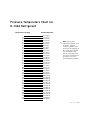
Pressure-temperature chart for R-134A refrigerant . . . . . . . . . . . . . E-1
F
Appendix
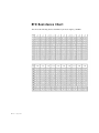
RTD resistance chart . . . . . . . . . . . . . . . . . . . . . . . . . . . . . . . . . . . . F-1
G
Appendix
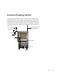
Overhead plumbing details . . . . . . . . . . . . . . . . . . . . . . . . . . . . . . . G-1
H
Appendix
Electrical schematic . . . . . . . . . . . . . . . . . . . . . . . . . . . . . . . . . . . . H-1
I
Appendix
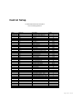
Control Setup . . . . . . . . . . . . . . . . . . . . . . . . . . . . . . . . . . . . . . . . . . I-1
J
Appendix
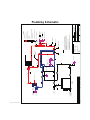
Plumbing schematic . . . . . . . . . . . . . . . . . . . . . . . . . . . . . . . . . . . . J-1
Ta b l e o f C o n t e n t s l i i i
i v l Ta b l e o f C o n t e n t s
SECTION
1
Purpose of the user guide . . . . . . . . . . . . . . 1-2
How the guide is organized . . . . . . . . . . . . . 1-2
Yo u r r e s p o n s i b i l i t i e s a s a u s e r . . . . . . . . . . . 1 - 3
AT T E N T I O N : R e a d t h i s s o n o o n e g e t s h u r t . . . 1 - 4
Introduction l 1-1
1
Introduction
Introduction
Purpose of the User Guide
This User Guide describes the EarthSmart ECM Series Chiller and
explains step-by-step how to install, operate, maintain and repair this
equipment.
Before installing this product, please take a few moments to read the User
Guide and review the diagrams and safety information in the instruction
packet. You also should review manuals covering associated equipment in
your system. This review won’t take long, and it could save you valuable
installation and operating time later.
How the Guide is Organized
Symbols have been used to help organize the User Guide and call your
attention to important information regarding safe installation and operation.
Symbols within triangles warn of conditions that could be hazardous to users or
could damage equipment. Read and take precautions before proceeding.
1
Numbers indicate tasks or steps to be performed by the user.
◆
A diamond indicates the equipment’s response to an action performed by the user.
❒
An open box marks items in a checklist.
•
A circle marks items in a list.
✒
✐
1-2 l Introduction
Indicates a tip. A tip is used to provide you with a suggestion that will help you with
the maintenance and the operation of this equipment.
Indicates a note. A note is used to provide additional information about the steps
you are following throughout the manual.
Yo u r R e s p o n s i b i l i t y a s a U s e r
• Thorough review of this User Guide, paying particular attention
to hazard warnings, appendices and related diagrams.
• Thorough review of the equipment itself, with careful attention
to voltage sources, intended use and warning labels.
• Thorough review of instruction manuals for associated equipment.
• Step-by-step adherence to instructions outlined in this User Guide.
Introduction l 1-3
1
Introduction
You must be familiar with all safety procedures concerning installation, operation and maintenance of this equipment. Responsible safety procedures include:
AT T E N T I O N :
Read this so no one gets hurt
We design equipment with the user’s safety in mind. You can avoid the potential
hazards identified on this machine by following the procedures outlined below and
elsewhere in the User Guide.
WA R N I N G : I m p r o p e r i n s t a l l a t i o n , o p e r a t i o n o r
servicing may result in equipment damage or
p e r s o n a l i n j u r y.
This equipment should be installed, adjusted and serviced by a qualified technician who is familiar with the construction, operation and
potential hazards of this type of machine.
All wiring, disconnects and fuses should be installed by a qualified
electrical technician in accordance with electrical codes in your region.
Always maintain a safe ground. Do not operate the equipment at power
levels other than what is specified on the machine serial tag and data
plate.
WA R N I N G : Vo l t a g e h a z a r d
This equipment is powered by single-phase alternating current,
as specified on the machine serial tag and data plate.
A properly-sized conductive ground wire from the incoming power
supply must be provided. Improper grounding can result in severe
personal injury and erratic machine operation. (Units are supplied with
a grounded plug that must be plugged into a grounded out.)
Always disconnect and lock out the incoming main power source before
opening the electrical enclosure or performing non-standard operating
procedures, such as routine maintenance. Only a qualified technician
should perform troubleshooting procedures that require access to the
electrical enclosure while power is on.
1-4 l Introduction
(continued)
AT T E N T I O N :
Read this so no one gets hurt
(continued)
Always protect yourself from hot surfaces when working on the
chiller, especially when working on or around the compressor and
condenser. These devices can be over 160°F {71°C}. Allow these
devices to cool before performing any maintenance or
troubleshooting.
WARNING: Refrigerant hazard
Only certified refrigerant technicians should examine and correct
problems involving the refrigerant circuit.
Introduction l 1-5
1
Introduction
CA U T I O N : H o t S u r fa c e s
1-6 l Introduction
SECTION
2
What is the EarthSmart ECM Series Chiller? . . 2-2
Ty p i c a l a p p l i c a t i o n s . . . . . . . . . . . . . . . . . . 2 - 2
Limitations . . . . . . . . . . . . . . . . . . . . . . . . 2-3
How it works: Process circulation . . . . . . . . 2-4
Refrigeration circulation . . . . . 2-5
Component listing . . . . . . . . . 2-6
Specifications: EarthSmart ECM
Series Chillers . . . . . . . . . . . . . . . . . . 2-8
Pump curve: EarthSmart ECM
Series Chillers . . . . . . . . . . . . . . . . . . 2-9
Description l 2-1
2
Description
Description
✐
What is the EarthSmart ECM Series
Chiller?
NOTE: Chiller’s environment
and cooling temperatures
below the default cooling
The Conair EarthSmart ECM Series Chillers provide self-contained sources of
chilled water and are available with compressor ranges of 0.5 Hp or 0.75 Hp
(nominal capacities of 0.41 tons or 0.70 tons of refrigeration).
ranges will affect cooling
capacities.
IMPORTANT: Nominal chilling capacities are based on 95°F {35°C} ambient air conditions and
processing 50°F {10°C} leaving water.
ECM Series Chillers are designed to provide chilled fluid for industrial applications requiring 24-hour-a-day performance. Units are totally self-contained for
easy, economical installation. All parts wetted by the process are non-ferrous.
Ty p i c a l A p p l i c a t i o n s
ECM Series Chillers can be used anywhere a reliable source of process cooling
water at temperatures ranging from 45° to 65°F {7.2°C to 18.3°C} is required.
These chillers at full load, will discharge approximately 7,500 or 12,500
BTU/hr of heat into the atmosphere (depending on model).
Chillers are available for:
Injection molding
● Blow molding
● Thermoforming
● Extrusion
● Air compressors
● Metal plating
●
2-2 l Description
Dryer intercoolers/aftercoolers
● Heatset/web offset printing presses
● Degreasing
● Laser
● Anodizing
●
Limitations
Conair EarthSmart ECM Series Chillers are chosen based on the cooling load,
ambient temperature and cooling temperature.
●
Ambient temperature - The chiller’s air-cooled condenser requires an
ambient air temperature between 40° to 95°F {4.4° to 35°C} for efficient
operation. Operation above 95°F {35°C} may result in elevated condensing
pressures and will eventually cause the chiller to shut down due to a high
pressure safety switch. Contact Conair Service for information for operating
within ambient air temperatures above 95°F {35°C} or below 40°F {4.4.°C}.
●
Temperature - As standard, ECM Series Chillers can provide cooling
temperature ranges of 45°F to 65°F {7.2°C to 18.3°C}. For cooling
temperatures below 45°F {7.2°C}, contact Conair Service.
Use this information as a general guide. Consult your Conair representative for
assistance when choosing a Conair EarthSmart ECM Series Chiller.
Description l 2-3
2
Cooling load - Choose a chiller that has 0 - 10% more cooling capacity than
the process load to be chilled.
Description
●
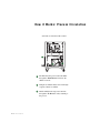
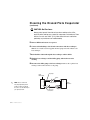
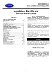
H o w i t Wo r k s : P r o c e s s C i r c u l a t i o n
(Left-side as viewed from the control)
1
3
2
1 Hot fluid from the process enters the chiller
through the “From Process” inlet into the
chiller’s reservoir.
2 Pump moves fluid from the reservoir through
evaporator where it is chilled.
3 Fluid is chilled in the evaporator and exits
through the “To Process” outlet, returning to
the process.
2-4 l Description
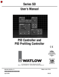
H o w i t Wo r k s : R e f r i g e r a n t C i r c u l a t i o n
(Left-side as viewed from the control)
(Right-side as viewed from the control)
From Process inlet
Pump
To Process outlet
1
4
Drain/Fill
1 The evaporator extracts heat from the process fluid,
causing the refrigerant to vaporize (evaporate) into a gas.
2
Vaporized refrigerant travels to the compressor, where the
low-pressure vapor is compressed into a high-pressure,
high-temperature vapor.
3 The high-pressure, high-temperature vapor travels from the
compressor through the condenser, where the fan cools
and condenses the vapor into a high-pressure, hightemperature liquid.
4
High-pressure, high-temperature liquid is metered back to
the evaporator by the expansion valve (TXV), changing it
to a low-pressure, low-temperature vapor.
Description l 2-5
2
Description
2
3
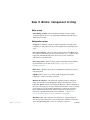
H o w i t Wo r k s : C o m p o n e n t L i s t i n g
Water system
• Motor/Pump assembly - The motor/pump assembly circulates chilled
coolant through the process loop. The pump assembly is built with brass to
maintain water quality.
Refrigeration system
• Compressor - Hermetic compressor takes low-pressure, low-temperature
refrigerant gas and compresses the gas into high-pressure, high-temperature
vapor.
• Air-cooled condenser - The air-cooled condenser removes heat BTUs from
the compressor refrigerant gas. The action causes the gas to “condense” into a
liquid state still under high pressure. Air flow across the condenser is
achieved by a motor driven fan.
• Fan cycling switch - The fan cycling switch is adjustable when the chiller is
in an environment cooler than 95°F {35°C}. See Appendix J entitled,
Plumbing Schematic.
• Filter-dryer - The filter-drier removes contaminants and moisture from the
liquid refrigerant.
• Liquid receiver - Serves as a collection tank for high-pressure liquid
refrigerant to ensure total charge at all times.
• Refrigerant sight glass - The refrigerant sight glass indicates refrigerant
charge and moisture content. Refrigerant charge is determined by a clear
liquid flow. Bubbles indicate low refrigerant. Moisture content is indicated by
the color of the sight glass view port element. The element’s color is normally
green. If the color of the element is dark brown or yellow, the system has
been contaminated with moisture and the refrigerant circuit needs to be
serviced by a qualified refrigerant service technician. See Maintenance
section entitled, Checking the Refrigerant Charge and Quality.
• Expansion valve - The expansion valve meters flow of liquid refrigerant
into the evaporator and creates a pressure drop in the refrigerant system that
allows the liquid refrigerant to “boil off” inside the evaporator.
2-6 l Description
(continued)
H o w i t Wo r k s : C o m p o n e n t L i s t i n g
(continued)
• Evaporator - The evaporator is a brazed plate heat exchanger where the
liquid refrigerant is allowed to evaporate (boil off) to absorb the heat (BTU)
from the process fluid. As the heat is absorbed, the process fluid is chilled.
NOTE: The fan cycling switch
is adjustable when the chiller
is in an environment cooler
than 95°F {35°C}. See
Appendix J entitled, Plumbing
Schematic.
IMPORTANT: Altering the High Pressure Switch setting will void any chiller warranty.
Description l 2-7
2
refrigeration system from unsafe operating levels. The high pressure switch
is factory set to open at 230 PSI and protects the refrigeration components
and personnel from potential damage or injury from excessively high
pressure. The high pressure safety must not be altered in the field for any
reason. The low pressure switch is factory set to open at 25 PSI and to close
at 35 PSI. The low pressure switch protects the chillers from possible damage
due to low operating pressure. The low pressure switch is field adjustable for
setpoints below 45°F {7.2°C}, contact a Conair representative for more
information.
✐
Description
• High/Low Pressure Switches: The high/low pressure switches protect the
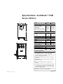
S p e c i f i c a t i o n s : E a r t h S m a r t TM E C M
Series Chillers
MODEL
Performance characteristics
Capacity* tons
Compressor Hp {kW}✝
B
Pump Hp {kW}
Chilled water flow‡ gpm {lpm}
Chilled water pressure‡ psi {bar}
A
Reservoir capacity gal {liters}
Dimensions inches {mm}
A - Height
B - Width
C - Depth
Process connections inches {mm}
Process (to and from)
Weight lb {kg}§
Installed
Shipping
Voltages full load amps**
115V/1 phase/60Hz
220V/1 phase/60Hz
Refrigerant
ECM-0.5
ECM-0.75
0.41
0.5 {0.37}
0.25 {0.19}
0.9 {3.4}
60 {4.1}
10 {37.8}
0.70
0.75 {0.56}
0.5 {0.37}
1.7 {6.4}
60 {4.1}
10 {37.8}
39.7 {1008}
18.7 {475}
24.2 {615}
39.7 {1008}
18.7 {475}
24.2 {615}
0.5
0.5
223 {101}
170 {77}
233 {106}
180 {82}
14
NA
NA
11
R-134A
Refrigerant charge lb {kg}
1.3 {0.6}
1.3 {0.6}
SPECIFICATION NOTES:
* Ton capacity at 12,000 BTU/ton @ 50°F {10°C} leaving
water temperature @ 115°F {46°C} condensing temperature. Capacities may be ± 5% as reserved by the
compressor manufacturer. Capacity multipliers are: 50°F
{10°C} - 1.00; 40°F {4.4°C} - 0.80.
✝ The ECM Series Chiller uses a hermetic reciprocating
C
compressor.
‡ Consult pump curve for exact characteristics relating to
pump performances.
§ Chiller installed weight includes a completely filled
reservoir.
** No allowance for inrush current. Ground fault interruption
to be supplied by the customer. Full load amps must be
used to size supply conductors. Consult a Conair representative for 50 Hz operation.
Specifications can change at any time. Contact your Conair
representative for the most current information.
2-8 l Description
TPHS039-1208
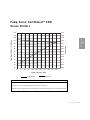
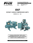
P u m p C u r v e : E a r t h S m a r t TM E C M
Series Chillers
140
0.65
130
0.60
120
0.55
0.50
100 GPH
100
0.45
90
0.40
80
0.35
70
0.30
60
0.25
50
0.20
40
0.15
30
0.10
20
0.05
10
0.00
25
25
50
75
100
125
150
175
200
225
Horsepower
Flow Rate (GPH at 1725 RPM)
110
250
Outlet Pressure* (PSI)
Horsepower
Flow rate
SPECIFICATION NOTES
* Pump curves do not reflect pressure drops due to internal piping.
This pump curve is non-overloading using the service factor of the motors.
Specifications may change without notice. Check with your Conair representative for the most current information.
Description l 2-9
2
Description
100 GPH
2-10 l Description
SECTION
3
Installation
Unpacking the boxes . . . . . . . . . . . . . . . . . 3-2
Wa r n i n g s a n d c a u t i o n s . . . . . . . . . . . . . . . . 3 - 3
Making process plumbing connections . . . . . 3-5
Fi l l i n g t h e c h i l l e r . . . . . . . . . . . . . . . . . . . 3 - 6
Drain connection . . . . . . . . . . . . . . . . . . . . 3-7
Checking the refrigerant charge . . . . . . . . . 3-8
Connecting the main power . . . . . . . . . . . . . 3-9
Installation l 3-1
3
Installation
Preparing for installation . . . . . . . . . . . . . . 3-4
Unpacking the Boxes
The EarthSmart ECM Series Chiller comes fully assembled in a single crate.
Units are shipped with the casters attached.
CAUTION: Lifting
Conair EarthSmart ECM Series Chillers are designed to easily roll on casters. If, for
some reason you need to lift the chiller, take all precautions to avoid personal
injury or damage to the chiller. Lift the chiller using a forklift or hoist with straps
that have been positioned at the chiller’s center of gravity. Do not try to lift the
chiller manually.
1 Carefully uncrate the chiller and its components.
2 Remove all packing material, protective paper, tape and plastic. Compare
contents to the shipping papers to ensure that you have all the parts.
3 Carefully inspect all components to ensure no damage occurred during shipping. If any damage is found, notify the shipping agent immediately to file a
claim. Check all wire terminal connections, bolts and any other electrical connections, which may have come loose during shipping. Check for pinched
wires and kinked hoses.
4 Cut the bands holding the chiller onto the pallet.
5 Record serial numbers and specifications for the chiller in the blanks
provided on the back of this User Guide’s title page. This information will be
helpful if you ever need service or parts.
3-2 l Installation
Wa r n i n g s a n d C a u t i o n s
WARNING: Improper installation, operation, or
servicing may result in equipment damage or
p e r s o n a l i n j u r y.
This equipment should only be installed, adjusted and serviced by a qualified
technician who is familiar with the construction, operation and potential
hazards of this type of machine.
All wiring, disconnects and fuses should be installed by a qualified electrical
technician in accordance with electrical codes in your region. Always maintain
a safe ground. Do not operate this equipment at power levels other than what
is specified on the machine data plate.
Always protect yourself from hot surfaces when working on the chiller,
especially when working on or around the compressor and condenser. These
devices can over 160°F {71°C}. Allow these devices to cool before performing
any maintenance or troubleshooting.
CAUTION: Ventilation
The unit requires a clean and well ventilated operating environment. Do not
place anything on top of the unit while operating.
Units require enough clearance around the perimeter for access panels to be
removed completely. Units require a minimum of 2 ft {0.6 m} clearance around
the perimeter for proper air flow.
WARNING: Refrigerant hazard
Only certified refrigerant technicians should examine and correct problems
involving the refrigerant circuit.
Installation l 3-3
3
Installation
CAUTION: Hot Surfaces
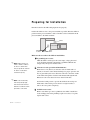
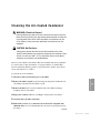
Preparing for Installation
Plan the location for the chiller and prepare the area properly.
Position the chiller as close to the process machine as possible. Place the chiller in
position near the process machine so that coolant lines can be connected from the
process machine to the chiller and back.
Chiller
Process machine
Alternate
locations
Make sure the area where the chiller is installed has:
✐
NOTE: Models must be positioned so that the condenser
air inlet is no warmer than
95°F {35°C} and the condenser
air outlet is not blocked or
restricted in any way.
✐
❒ A grounded power source.
Check the chiller’s serial tag for the correct amps, voltage, phase and
cycle. All wiring should be completed by a qualified technician and
comply with your region’s electrical codes.
❒ Clearance for safe operation and maintenance.
Ensure there is 2 ft {0.6 m} of clearance at the air intake and 2 ft
{0.6 m} of clearance at the exhaust discharge for proper operation. Air
flow is generated by the motor driven fan. Air flow is from the outside
of the chiller, through the condenser and exhausted through the unit.
Exhaust air can not be ducted on motor driven fan models.
NOTE: Locate models away
from heat producing equipment. These items will affect
ambient air conditions and the
performance of the chiller.
3-4 l Installation
Position the locking casters to prevent the chiller from moving. For
maintenance and servicing, be sure there is enough clearance to
remove all access panels completely.
❒ Available water source.
Ensure water make-up source is plumbed to the chiller’s installation
location. High points in the plumbing require vent valves; low points
require drain valves.
Making Process Plumbing
Connections
✐
control depends on the method
All process piping materials (such as hoses, rigid piping, valves or filters) used
with process water piping circuitry must be rated for 100°F {37.8°C} minimum
temperature and 150 PSI {10.3 bar} minimum pressure.
All such materials must have the equivalent or larger diameter of the particular
process connection that the length of process water piping is connected to.
NOTE: The ability of the unit to
maintain process temperature
of installation.
✐
NOTE: Assure the piping
installation has continuous
Process water piping circuitry should be designed to avoid an excessive use of
elbows and/or lengths of pipe or hose. If hose is the material of choice, avoid
tight twists or curls and excessive lengths.
mechanical valve to regulate
process flow you MUST install
a bypass in the process
piping.”
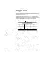
Warm coolant from process equipment enters the chiller at the “From Process”
inlet and chilled coolant returns to the process equipment through the “To
Process” outlet.
To connect process plumbing:
1 Remove the shipping plastic pipe plugs from the female “To Process” and
“From Process” connections on the back of the portable chiller.
From Process
inlet
2 Make sure the male pipe threads are clean and new.
3 Wrap the male pipe threads with Teflon tape or pipe dope.
To Process
outlet
4 Connect the “From Process” valve (factory optional) on the back of the
chiller to the “From Process” tubing that is from the “Water Out” manifold on the mold or process. Start by hand until the threads engage and then
tighten with an appropriately-sized pipe wrench. Tighten only enough to prevent leaks; do not over-tighten.
Fill/drain port
5 Connect the “To Process” valve (factory optional) on the back of the chiller
to “To Process” tubing that is from the “Water In” manifold on the mold
or process. Start by hand until the threads engage and then tighten with an
appropriately-sized pipe wrench. Tighten only enough to prevent leaks; do not
over-tighten. If process lines are higher than the chiller, see Appendix G, entitled
Overhead Plumbing Details.
Installation l 3-5
3
Installation
Valves and filters may be installed in the process water piping circuitry to
facilitate service and maintenance provided that these devices maintain the full
inside diameter of the process connection. If installed, all devices must be open
and clean during unit operation.
flow at all times. If using a
Filling the Chiller
The chiller is shipped without coolant. The chiller is manually filled during installation using water as its coolant.
For atypical process temperatures below 45°F {7.2°C}, use the table below to
determine the percentage (by volume) of glycol needed for the process temperature that is required. Mix the proper percentage of glycol with water.
IMPORTANT: The chiller’s control does not monitor the percentage mixture of glycol.
Recommended Percentages of Glycol for
Chilled Water Freeze Protection (by volume)
IMPORTANT: Evaporator freeze-ups
are not covered under warranty.
Discharge water
% Propylene
% Water
Temperature
Glycol
40°F
20
80
30°F
30
70
25°F
40
60
To fill with water:
1 Attach the water supply to the Fill/Drain valve, located on the back of the
chiller.
2 Open the “To Process” and “From Process” valves (factory optional).
3 Open the Fill/Drain valve or water supply and fill the chiller to the 7/8 full
level on the water level gauge. If the chiller is overfilled, the excess water
spills out the vent tube. DO NOT OVERFILL.
4 Close the Fill/Drain valve.
5 Check the coolant level. When the chiller is turned on the coolant level drops
as it begins to circulate, filling the connected plumbing. Check the
coolant level on the back of the chiller. Make sure the coolant level is filled to
the 7/8 full level on the water level gauge. Shut down the chiller and add more
coolant, if needed.
6 Disconnect water hose from Fill/Drain valve, if the chiller is to be used
3-6 l Installation
elsewhere.
Drain Connection
To drain the chiller for storage or transport:
1 Rotate the chiller’s drain valve counterclockwise. If using chemicals or
additives with your process coolant, observe local disposal laws and regulations.
From Process inlet
Water level gauge
To Process outlet
2 Close the chiller’s drain valve by turning it clockwise once final
evacuation of all process coolant is complete.
IMPORTANT: Drainage procedures must be done prior to shipment or outdoor storage of
the unit. If not, freezing damage can occur.
IMPORTANT: Ensure long-term storage environments are above freezing temperatures. If
not, allow the chiller to thaw for several hours before returning it to operation or fill the
chiller’s internal piping with a high mixture of glycol to water during storage.
Installation l 3-7
3
Installation
Fill/drain port
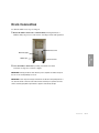
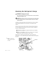
Checking the Refrigerant Charge
WARNING: Refrigerant hazard
Only certified refrigerant technicians should examine and correct problems
involving the refrigerant circuit.
CAUTION: Always disconnect and lock out the main power sources before making
electrical connections. Electrical connections should be made only by a qualified
electrical technician.
All chillers are fully charged with R-134A refrigerant from Conair. Your chiller’s
model nameplate identifies the type and amount of total refrigerant charge
required.
Check the refrigerant charge while the chiller is running through the sight glass.
Locate the sight glass by removing the left-side panel and using a flashlight, if
necessary to check the sight glass:
❒ Under full load conditions, the refrigerant should be clear (no bubbles).
❒ Under low load conditions, when the Hot-gas Bypass valve is energized,
bubbles may be visible in the sight glass. This is normal.
✐
If the charge is low and the unit is under warranty, contact Conair service.
Otherwise have a local, certified refrigeration technician add R-134A refrigerant to
the system.
NOTE: In this diagram, the
chiller’s panels are removed
for clarity.
3-8 l Installation
Sight glass
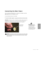
C o n n e c t i n g t h e M a i n Po w e r
The Conair EarthSmart ECM Chiller uses standard 115 Volt, 60 Hz or 220 Volt,
60Hz single-phase power, depending on model.
To connect the the main power to the chiller:
1 Connect the chiller’s plug into a properly-sized and rated electrical outlet.
IMPORTANT: Depending on the state of the refrigeration system the compressor may turn on
momentarily upon connecting power. The compressor will stop when the refrigerant is
pumped into the condenser and a low pressure condition exists in the evaporator.
CAUTION: Always disconnect and lock out the main power sources before making
electrical connections. Electrical connections should be made only by a qualified
electrical technician.
Installation l 3-9
3
IMPORTANT: Always refer
to the wiring diagrams that
came with your chiller to
locate specific electrical
components. Illustrations in
the User Guide are intended
to be representative only.
Installation
220 Volt/60 Hz,
20 amp plug
3-10 l Installation
SECTION
4
Operation
EarthSmart ECM Series Chiller:
Control descriptions . . . . . . . . . . . . . . . 4-2
Stopping the chiller . . . . . . . . . . . . . . . . . . 4-4
Changing temperature units . . . . . . . . . . . . 4-5
Chiller operation sequence . . . . . . . . . . . . . 4-6
Resetting the high pressure switch
of the compressor . . . . . . . . . . . . . . . . 4-8
Operation l 4-1
4
Operation
Starting the chiller . . . . . . . . . . . . . . . . . . 4-3
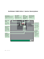
EarthSmart ECM Chiller: Control Descriptions
Return Button
Pressing the “Return” button will
scroll through the chiller’s menu
screens.
Actual Chiller
Te m p e r a t u r e
Hot-Gas
Bypass Status
Shows the (process) actual
temperature value.
Indicates the status
of the Hot-Gas
Bypass valve.
Alarm Indication
Indicates the alarm status. (High Temperature
Alarm only.)
O n / O f f To g g l e
Switch
Used to turn the
power to the chiller
on or off.
Infinity Button
Pressing the
“Infinity” button
will acknowledge
alarms and return
the user to the Main
screen.
Setpoint
Te m p e r a t u r e
Shows the userentered setpoint
temperature value.
4-2
l Operation
SD
1
2
Control Codes
%
See See Troubleshooting section for
a list of possible
causes and solutions
for alarm conditions.
Increment/
Decrement
Buttons
Used to increase or
decrease the userentered process
temperature setpoint.
Infinity Button
Pressing the “Infinity” button will acknowledge alarms
and return the user to the Main screen.
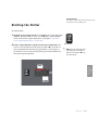
Starting the Chiller
To start the chiller:
1 Toggle the power switch to the On or “I” position. The control display will
illuminate. Facing the chiller’s control, the “To Process” actual temperature
will be on the left, the setpoint temperature is on the right. See Operation
section entitled, Chiller Sequence of Operation.
2 Set the cooling temperature setpoint. Use the up arrow button ▲ on the
control, to raise the setpoint. Use the down arrow button ▼ to lower the setpoint. The temperature will ramp up at approximately 1 (one) degree per
second. After 2 (two) seconds of inactivity the setpoint entered will become
the targeted setpoint temperature.
On Position
✐
NOTE: If the setpoint displays “OFF”
in the display, raise the setpoint
with the up arrow button ▲ to see
the actual setpoint.
2
%
Operation l 4-3
4
Operation
SD
1
Stopping the Chiller
To stop the chiller:
1 Toggle the power switch to the Off or “O” position.
SD
1
2
%
Off Position
IMPORTANT: Do NOT rapidly cycle the chiller’s power on and off (short cycle). Once the
power has been turned off, wait at least three (3) minutes before cycling the chiller’s
power back on.
4-4
l Operation
C h a n g i n g Te m p e r a t u r e U n i t
To stop the chiller:
1 Press the green “Return” button
once to access the Temperature Units
Selection screen. Press the ▲ or ▼ buttons to toggle between fahrenheit and
celsius temperature units.
✐
NOTE: The temperature display will
not indicate Fahrenheit or Celsius
temperature units. The chiller’s
control is set for Fahrenheit temperature units as standard from
Conair.
SD
1
2
%
Return
Button
to lock in the selection and return to the
Main screen. The control will default back to the Main screen if no buttons are
pressed after 1 minute.
SD
1
2
%
Infinity
Button
Operation l 4-5
4
Operation
2 Press the “Infinity” button
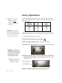
Chiller Operation Sequence
The EarthSmart ECM Series Chiller has a unique user interface that controls the
process temperature and prevents refrigeration migration during compressor off
times.
When the main power is connected:
1 Depending on the state of the refrigeration system, the compressor may
turn on momentarily upon connecting power. The compressor will stop when
the refrigerant is pumped into the condenser and a low pressure condition exists
in the evaporator.
When the power toggle switch is turned to the “On”or “I” position:
2 Turning the toggle switch on immediately starts the process pump and
illuminates the control. When flow is established and the unit is not in a low
temperature alarm, the Liquid Line Solenoid valve (LLSV) will open. This
allows the refrigerant to migrate to the evaporator and increase the pressure.
When the low refrigerant pressure switch is satisfied the compressor will turn on
and process coolant will begin cooling.
3 When the process temperature is above setpoint the compressor will run
and the Hot-Gas Bypass valve (HGBP) will not open. If the process
temperature falls below the setpoint, the HGBP valve will energize, raising the
actual process temperature to maintain the user-entered setpoint temperature.
The HGBP valve can energize up to 9 out of 10 seconds. If there is less load
on the chiller and the temperature continues to fall to 4°F {2.2°C} below the
user-entered setpoint the controller will alarm (A2.lo) and close the LLSV. The
compressor will pump the refrigerant out of the evaporator and the low pressure
switch will shut off the compressor. This is a normal function of the chiller and
will not require troubleshooting.
4 The controller stays in this alarm condition (A2.lo) until the temperature is
2°F {1.1°C} above the user-entered setpoint, at which point the controller
allows the LLSV to re-open and the compressor to restart.
(continued)
4-6
l Operation
Chiller Operation Sequence
(continued)
5 The condenser fan can energize anytime the toggle switch is in the “On”
or “I” position. The fan is controlled by the fan cycling (high refrigeration)
pressure switch. This switch maintains the high side refrigeration pressure
under cooler ambient temperatures and lower loads. The fan will turn on when
the high refrigeration pressure reaches 200 PSI {13.8 bar}. It will turn off
when the pressure drops below 125 PSI {8.6 bar}.
6 The high refrigeration safety pressure switch shuts off the compressor
immediately when the high refrigeration pressure reaches 230 PSI
{15.9 bar} without going through pump down during a low pressure cycle.
If the high pressure switch trips, it must be manually reset by pressing the
“Reset” button on the switch. The compressor can start immediately when
this is reset so caution should be exercised. See Operation section entitled,
Resetting the Compressor’s High Pressure Switch.
CAUTION: The compressor can start immediately when the High Pressure “Reset”
button is pressed.
4
Operation
Operation l 4-7
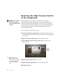
Resetting the High Pressure Switch
of the Compressor
CAUTION: The compressor can
start immediately when the
High Pressure “Reset” button
is pressed.
The high refrigeration safety pressure switch shuts off the compressor
immediately when the high refrigeration pressure reaches 230 PSI {15.9 bar}
without going through pump down during a low pressure cycle. If the high
pressure switch trips, it must be manually reset by pressing the “Reset” button
on the switch. The compressor can start immediately when this is reset so
caution should be exercised.
To reset the high refrigeration safety switch:
1 Be sure the main power is disconnected and the chiller is locked out. Always
disconnect/unplug and/or lockout the main power source before opening the unit
for servicing.
2 Remove the chiller’s right-side panel, as viewed from the control.
3 Locate the high refrigeration safety switch within the top portion of the
chiller’s cabinet.
Reset
Button
✐
NOTE: The High Pressure
Safety switch may not reset
due to the chiller’s refrigerant
state. Allow the refrigerant to
cool before attempting to
reset.
4 Push the “Reset” button, until there is a “click”.
5 Replace the chiller’s right-side panel, as viewed from the control.
6 Reapply main power.
4-8
l Operation
SECTION
5
Maintenance
Preventative maintenance schedule . . . . . . . 5-2
Checking electrical connections . . . . . . . . . . 5-4
Cleaning the brazed plate adapter . . . . . . . . 5-5
C l e a n i n g t h e a i r- c o o l e d c o n d e n s e r . . . . . . . . 5 - 7
Checking the reservoir level . . . . . . . . . . . . 5-9
Cleaning the pump strainer . . . . . . . . . . . . 5-10
Checking the refrigerant charge
Maintenance l 5-1
5
Maintenance
and quality . . . . . . . . . . . . . . . . . . . . 5-12
Preventative Maintenance Schedule
Daily, or as often as needed
❒
Checking process fluid level in the pump tank
Check the process fluid level in the water level gauge on the back of the
chiller. If low, see Maintenance section entitled, Checking the Reservoir
Level.
❒
Verifying pump discharge pressure
While the pump is running, check to ensure that the pump pressure gauge
(located on the front of the chiller) is within range. To change the pressure,
open or close the “To Process” valve (factory optional).
❒
Inspecting piping for leaks
Check to see that pipes are not leaking. Look for standing water on the floor
or inside the chiller cabinet.
❒
Inspecting the condenser coil for debris
Check the condenser for adequate air flow. Check the condenser face for
dirt and clogging. If dirt or clogs are present, clean the condenser, see
Maintenance section entitled, Cleaning the Air-cooled Condenser. Check,
clean, and/or replace the filter at the air inlet of the air-cooled condenser coil,
as needed.
Weekly, or as often as needed
5-2 l Maintenance
❒
Checking temperature and pressure readings
Check that the temperature displays on the control screen and the reading on
the pressure gauge (located on the front of the chiller) indicates normal
operation. See Description section entitled, Pump Curve: EarthSmart ECM
Series Chillers.
❒
Inspecting the filter
Check, clean and/or replace the filter at the air inlet of the air-cooled condenser coil, as needed. see Maintenance section entitled, Cleaning the Aircooled Condenser.
❒
Checking refrigerant site glass
There should not be any bubbles. See Maintenance section entitled,
Checking the Refrigerant Charge and Quality.
❒
Checking reservoir level
Check the water level gauge on the back of the chiller. If fluid level is low,
fill, see Maintenance section entitled, Checking Reservoir Level.
(continued)
Preventative Maintenance Schedule
(continued)
Monthly
❒
Checking electrical connections, amps and volts
Check to ensure the electrical connections are properly seated and that the
chiller is operating at its rated amps and voltage. See Description section
entitled, Specifications: EarthSmart ECM Series Chillers.
❒
Cleaning
Wipe all external surfaces to maintain performance.
❒
Inspecting condenser
Check the air-cooled condenser for adequate air flow. Check the condenser
face for dirt and clogging. If dirt or clogs are present, clean the condenser.
Check, clean and/or replace the filter at the air inlet of the air-cooled condenser coil, as needed. See Maintenance section entitled, Cleaning the Aircooled Condenser.
❒
Inspecting the control panel
Check for loose wires, burned contacts and signs of overheated wires.
Check that all panel lights illuminate. See Maintenance section entitled,
Checking Electrical Connections.
❒
Checking refrigerant charge and quality
With the compressor running, check the sight glass between the receiver and
evaporator for proper refrigerant condition. See Maintenance section entitled,
Checking Refrigerant Charge and Quality.
❒
Checking the pump strainer.
Check to ensure the pump strainer is not clogged or damaged, replace as
needed. See Maintenance section entitled, Cleaning the Pump Strainer.
Annually
❒
Cleaning the evaporator
See Maintenance section entitled, Cleaning the Brazed Plate Evaporator.
❒
Check refrigerant piping
Verify that no oil is present on fittings or cabinet. Wipe clean and check
charge/operation of circuit.
Maintenance l 5-3
5
Inspecting cooling water treatment system
If your chiller uses a cooling water treatment system, maintain proper chemical levels and follow the recommendations of your water treatment specialist.
Change water in the reservoir tank monthly to reduce water hardness.
Maintenance
❒
Checking Electrical Connections
WARNING: Electrical Hazard
Before performing any work on this item, disconnect and lock out electrical power
sources to prevent injury from unexpected energization or startup. Be sure that
power to the chiller is OFF when doing any maintenance on the chiller. Follow all
safety rules when performing any maintenance on this equipment.
✐ NOTE: Always refer
to the wiring diagrams you received
with your chiller to
locate specific electrical components.
WARNING: Improper installation, operation or
servicing may result in equipment damage or
p e r s o n a l i n j u r y.
This equipment should only be installed, adjusted and serviced by a qualified
technician who is familiar with the construction, operation and potential hazards
of this type of machine.
All wiring, disconnects and fuses should be installed by a qualified electrical
technician in accordance with electrical codes in your region.
To check electrical connections:
1 Be sure the main power is disconnected and/or the chiller is locked out. Always
disconnect/unplug and lockout the main power source before opening the unit for
servicing.
2 Remove the chiller’s top lid, by first removing both side panels and then the four
(4) retaining bolts that secure the chiller’s top lid.
3 Inspect all wires and connections.
✐ NOTE: Also inspect
the chiller’s plug
wiring terminations.
Look for loose wires, burned contacts and signs of over-heated wires. Compare
the wiring to the wiring diagrams you received with your chiller. Have a qualified
electrician make any necessary repairs or replacements.
4 Replace the chiller’s side panels and then the top lid by replacing the four (4)
retaining bolts.
5 Inspect the exterior power cords.
5-4 l Maintenance
Cords should not be crimped, exposed or rubbing against the frame. If the main
power cord runs along the floor, make sure it is positioned where it could not rest
in pooling water or could not be ran over and cut by wheels or casters.
C l e a n i n g t h e B r a z e d P l a t e E va p o r a t o r
Minerals and other contaminants produce deposits, scales, slime or algae on the heat
transfer surfaces exposed to water. Fouled surfaces could result in decreased cooling
capacity. Implement a water treatment program to slow the fouling.
CAUTION: Hot Surfaces
Always protect yourself from hot surfaces when working on the chiller, especially when working on or around the compressor and condenser. These
devices can reach over 160°F {71°C}. Allow these devices to cool before
performing any maintenance or troubleshooting.
Water quality should be maintained at a pH level of 7.4, but not less than 6.0 for
proper heat exchanger life.
To clean the brazed plate adapter:
1 Prepare a 5% solution of Phosphoric acid or Oxalic acid and water. Do not
heat the acid solution.
2 Disconnect and/or lockout main power to the chiller.
3 Shut the “To” and “From Process” valves (factory optional) and the drain
reservoir. See Installation section entitled, Drain Connection.
5 Disconnect the pump from the heat exchanger. Install a cap in the opening of
the heat exchanger where the pump was connected.
✐
From Process inlet
NOTE: These connections
may vary depending on the
model you have purchased.
Be sure to see the labeling on
your particular unit.
Water level gauge
Fill/drain port
(continued)
To Process outlet
Maintenance l 5-5
5
Maintenance
4 Remove the chiller’s side panels.
C l e a n i n g t h e B r a z e d P l a t e E va p o r a t o r
(continued)
CAUTION: Hot Surfaces
Always protect yourself from hot surfaces when working on the chiller,
especially when working on or around the compressor and condenser. These
devices can reach over 160°F {71°C}. Allow these devices to cool before
performing any maintenance or troubleshooting.
5 Remove RTD from bottom of evaporator.
6 Connect 3/8-inch tubing to the 3/8-inch connections of the heat exchanger.
SEE below to install customer-supplied chemical pump and solution fitted to the
heat exchanger.
7 Back-flush the solution through the heat exchanger and the chiller.
8 Flush the heat exchanger and the chiller piping with fresh water after
cleaning.
9 Reconnect the chiller pump to the heat exchanger. Remove the cap in the heat
exchanger and reconnect the hose to the pump.
Heat
Exchanger
To pump
Valve
✐
NOTE: These connections
may vary depending on the
model you have purchased.
Be sure to see the labeling on
your particular unit.
5-6 l Maintenance
Acid
solution
Fluid circuit
To Process
connection
Pump
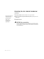
C l e a n i n g t h e A i r- C o o l e d C o n d e n s e r
WARNING: Electrical Hazard
Before performing any work on this item, disconnect and lock out electrical
power sources to prevent injury from unexpected energization or startup. Be
sure that power to the chiller is OFF when doing any maintenance on the
chiller. Follow all safety rules when performing any maintenance on this
equipment.
CAUTION: Hot Surfaces
Always protect yourself from hot surfaces when working on the chiller,
especially when working on or around the compressor and condenser. These
devices can reach over 160°F {71°C}. Allow these devices to cool before
performing any maintenance or troubleshooting.
The air-cooled condenser and condenser filter can accumulate dirt and clog quickly if
it is ran in a dusty or dirty environment. A clogged condenser or condenser filter
increases refrigerant discharge pressure, lowers performance, and may cause the fan
motors and compressor to overheat.
To clean the air-cooled condenser:
1 Disconnect and/or lockout main power to the chiller.
(4) retaining bolts that secure the chiller’s top lid.
3 Remove the filter, that is located towards the back of the chiller, by lifting it
straight up and out of the chiller.
4 Inspect the condenser coils. Use a flashlight to check between coil surfaces.
5 Clean the dirty coils with a soft brush.
6 Flush with cool water or a commercial coil cleaner that is compatible with
aluminum alloys. It is recommended that the coil cleaner is sprayed from inside
the cabinet.
(continued)
Maintenance l 5-7
5
Maintenance
2 Remove the chiller’s top lid, by first removing both side panels and then the four
C l e a n i n g t h e A i r- C o o l e d C o n d e n s e r
(continued)
7 Check the air filter. If the filter is blinded or torn, replace the filter.
Replacement air filters are
available from Conair.
8 Replace the chiller’s side panels and then the top lid by replacing the four (4)
retaining bolts.
Contact Conair Parts
(800) 458 1960
From outside of the
United States, call:
(814) 437 6861
9 Reapply main power.
CAUTION: Wear eye protection.
If you use compressed air to clean the equipment, you must wear eye protection and observe all OSHA and other safety regulations pertaining to the
use of compressed air.
5-8 l Maintenance
Checking Reservoir Level
WARNING: Electrical Hazard
Before performing any work on the chiller, disconnect and lock out electrical
power sources to prevent injury from unexpected energization or startup. Be
sure that power to the chiller is OFF when doing any maintenance on the
chiller. Follow all safety rules when performing any maintenance on this
equipment.
Check the coolant level in the reservoir. The coolant level in the sight glass on the
back of the chiller should be 7/8 full.
To manually fill the reservoir:
1 Disconnect and lockout power to the chiller.
2 Locate the Fill/Drain valve on the back of the chiller. Open the Fill/Drain valve
or coolant supply and fill the chiller to the 7/8 full level on the water level gauge.
If the chiller is overfilled, the excess water spills out the vent tube. DO NOT
OVERFILL.
3 Refill the reservoir. Monitor the level using the water level indicator on the back
of the chiller, ensuring you are adding the correct fluid for your application.
4 Close the Fill/Drain valve.
as it begins to circulate, filling the connected plumbing. Check the
coolant level on the back of the chiller. Make sure the coolant level is filled to
the 7/8 full level on the water level gauge. Shut down the chiller and add more
coolant, if needed.
6 Disconnect water hose from Fill/Drain valve, if the chiller is to be used
elsewhere.
Water level gauge
Fill/drain port
Maintenance l 5-9
5
Maintenance
5 Check the coolant level. When the chiller is turned on the coolant level drops
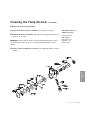
Cleaning the Pump Strainer
EarthSmart Chillers use a rotary pump to flow process coolant through their internal
piping and to the process. A strainer on the pump may periodically need cleaning,
depending upon the quality of the process coolant.
WARNING: Electrical Hazard
Before performing any work on the chiller, disconnect and lock out electrical
power sources to prevent injury from unexpected energization or startup. Be
sure that power to the chiller is OFF when doing any maintenance on the
chiller. Follow all safety rules when performing any maintenance on this
equipment.
To clean the pump’s strainer:
1 Be sure the main power is disconnected and/or the chiller is locked out. Always
disconnect/unplug and lockout the main power source before opening the unit for
servicing.
2 Drain all process coolant from the chiller, see Installation section entitled, Drain
Connection.
3 Remove the chiller’s right-side panel. (As viewed from the control)
4 Locate the chiller’s pump. It is located in the lower portion of the chiller’ cabinet
and towards the front of the chiller.
Strainer end cap
✐
NOTE: The front panel of the
chiller has been removed in
this image for clarity.
5 Locate the pump strainer’s end cap, remove the cap by unscrewing it counterclockwise with an appropriately-sized wrench.
(continued)
5-10 l Maintenance
Cleaning the Pump Strainer
(continued)
6 Remove the strainer from its housing.
7 Inspect the strainer for holes or blinding, clean or replace as necessary.
8 Re-install the strainer and strainer cap. Properly seal all piping with approved
Teflon tape or pipe dope.
IMPORTANT: Check to ensure the strainer is properly seated before applying the strainer
cap. Crushing of the strainer can occur if it is not fully inserted back into the strainer
housing.
Replacement strainers are
available from Conair.
Contact Conair Parts
(800) 458 1960
From outside of the
United States, call:
(814) 437 6861
9 Check to ensure no leaking has occurred before returning the chiller to normal
operation.
5
Maintenance
Maintenance l 5-11
Checking the Refrigerant Charge and
Quality
WARNING: Refrigerant Hazard
Only certified refrigerant technicians should examine and correct problems
involving the refrigerant circuit.
CAUTION: Always disconnect and lock out the main power sources before making
electrical connections. Electrical connections should be made only by a qualified
electrical technician.
All chillers are fully charged with R-134A refrigerant from Conair. Your chiller’s
model nameplate identifies the type and amount of total refrigerant charge required.
See Description section entitled, Specifications: EarthSmart ECM Series Chillers.
Check refrigerant charge while the chiller is running under normal load. Check the
refrigerant charge through the sight glass. Use a flashlight, if necessary, and check the
liquid-line sight glass:
✐
NOTE: In this diagram, the
•
Under full load conditions, the refrigerant should be clear (no bubbles).
•
Under low load conditions, when the Hot-Gas Bypass valve (HGBP) is
operating, bubbles may be visible in the sight glass. This is normal.
A refrigerant quality label is located within the sight glass. A green label is normal. A
yellow or dark brown label indicates that the refrigerant is contaminated and must be
replaced.
chiller’s panels are removed
for clarity.
If the charge is low or contaminated and the chiller is under warranty, contact Conair
service; or have a local, certified refrigeration technician service the system.
Sight glass
5-12 l Maintenance
SECTION
6
Tr o u b l e s h o o t i n g
Before beginning . . . . . . . . . . . . . . . . . . . . 6-2
A few words of caution
. . . . . . . . . . . . . . 6-3
DIAGNOSTICS
How to identify the cause of a problem . . . . 6-3
Alarms
. . . . . . . . . . . . . . . . . . . . . . . . . 6-4
Tr o u b l e s h o o t i n g . . . . . . . . . . . . . . . . . . . . 6 - 5
Checking or replacing the
temperature sensor . . . . . . . . . . . . . . . 6-8
Checking or resetting the circuit breakers . . . 6-9
6
Troubleshooting
Maintenance l 6-1
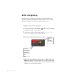
Before Beginning
You can avoid most problems by following the recommended installation and
maintenance procedures outlined in this User Guide. If you do have a problem,
this section will help you determine what caused it and how to fix it.
❏ Diagnose causes from the control panel.
1
Note the alarm and press the “Infinity”
the alarm and resume control if required.
2
Address the alarm message and fix the problem. See Troubleshooting
section for descriptions of possible alarm conditions.
3
If the alarm reappears the problem was not fixed.
button once to acknowledge
SD
1
2
%
This red light
indicates a
High
Temperature
alarm condition
The “Infinity”
button should be
pressed once to
acknowledge a
High Temperature
alarm.
❏ Find the wiring and equipment diagrams that were shipped with your
chiller. These diagrams are the best reference for correcting a problem. The
diagrams also will note any custom features, such as special wiring or alarm
capabilities, not covered in this User Guide.
6 - 2 l Tr o u b l e s h o o t i n g
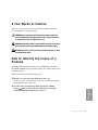
A Fe w Wo r d s o f C a u t i o n
Improper corrective actions can lead to hazardous conditions and should
never be attempted to sustain production.
WARNING: Only a qualified electrical technician should examine and
correct problems that require opening the chiller’s electrical enclosure
or using electrical wires to diagnose the cause.
WARNING: High voltage. Always stop the chiller, disconnect and lock out
the main power source before troubleshooting or performing repairs.
CAUTION: Hot surfaces. Always protect yourself from hot surfaces inside
and outside of the chiller.
How to Identify the Cause of a
Problem
The High Temperature Alarm is indicated by an illuminated alarm light on
the EarthSmart ECM control panel and an alarm code, (A2.hi) is displayed in
the control display.
When an alarm code is displayed in the control:
1 Find the error message in the diagnostics table of this
Troubleshooting section and reference the control labeling in the upper
right-hand side of the control face.
2 Note that, after correcting the problem, pressing the “Infinity”
Tr o u b l e s h o o t i n g l 6 - 3
6
Troubleshooting
button
will clear the alarm. The alarm will only clear if the
condition causing the alarm has been corrected.
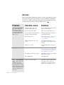
Alarms
If the red alarm LED is illuminated, an alarm is activated. The chiller has automatically pumped down because it has detected a serious problem that could damage
your process or chiller. Note that the alarm must be acknowledged before the control will resume operation by pressing the “Infinity” button.
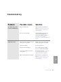
Problem
Possible cause
Solution
A2.hi (Alarm light illuminated) – If the “To Process”
temperature exceeds the
process high temperature deviation setpoint, it shuts down
the chiller. Default is set to
20°F {11.1°C}.
The Hot-gas Bypass valve is not
operating properly (stuck open).
Have a certified refrigeration technician
replace the solenoid valve.
Load is too high for the chiller.
Remove some load from the process.
Process coolant is not flowing between
the supply outlet and return inlet.
Check for plugged pipes, closed valves,
or failed flow switch(es).
Dirty condenser coil.
Clean condenser coil. See Maintenance
section entitled, Cleaning the Aircooled Condenser.
Ambient temperature is above 95°F
{35°C}.
Lower ambient temperature or move
the chiller to a lower temperature environment.
Warm process coolant.
Lower the temperature of the process
coolant.
Failed RTD.
Replace the RTD. See Troubleshooting
section entitled, Checking or Replacing
the Temperature Sensor and Appendix F
entitled, RTD Resistance Chart.
Loose RTD connection to the control.
Check RTD connection to the controller.
Resecure as necessary.
Reversed RTD input.
Check RTD wiring.
Load is too low for the chiller.
The chiller’s compressor will automatically restart once the “To Process”
temperature exceeds the user-entered
setpoint on the control by 2°F {1.1°C}.
Er.in (Input error)
A2.lo – (Alarm light illuminated) – If the “To Process”
temperature exceeds the
process low temperature deviation setpoint, it closes the liquid line solenoid valve and the
compressor pumps down and
shuts down. Default is set to
4°F {2.2°C}.
6 - 4 l Tr o u b l e s h o o t i n g
Tr o u b l e s h o o t i n g
Solution
The chiller will not start.
(Control not illuminated)
Tripped circuit breaker.
Verify resistance to ground. Reset
breaker. See Troubleshooting section
entitled, Checking or Resetting the
Circuit Breakers.
Incorrect incoming voltage.
Check incoming power source for
correct voltage and amperage as
detailed on the chiller nameplate. See
Description section entitled,
Specifications: EarthSmart ECM Series
Chillers.
The power toggle switch is not turned
to the “On” or “I” position.
Turn the power toggle switch on the
control to the “On” or “I” position.
Open motor winding.
Contact Conair Service.
Internal overload has tripped.
Auto-resetting. Allow the chiller’s
motor to cool and restart the chiller.
Loose wire connection or defective
start capacitor.
Check wiring diagrams, see Appendix
H entitled, Electrical Schematic,
replace connections or capacitor.
CB2 circuit breaker has been tripped.
Verify resistance to ground. Reset
breaker. See Troubleshooting section
entitled, Checking or Resetting the
Circuit Breakers.
Pump will not start.
Tr o u b l e s h o o t i n g l 6 - 5
6
Possible cause
Troubleshooting
Problem
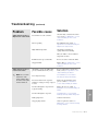
Tr o u b l e s h o o t i n g
Problem
Compressor will not start.
✐
NOTE: Also, see
Troubleshooting section,
entitled, Troubleshooting,
“Chiller shuts down due
to a High Pressure switch
alarm” and “Chiller shuts
down due to a Low
Pressure switch”.
(continued)
Possible cause
Solution
High pressure switch has been tripped.
Reset the High Pressure switch. See
Operation section entitled, Resetting
the High Pressure Switch.
Circuit breaker has been tripped.
Verify resistance to ground. Reset
breaker. See Troubleshooting section
entitled, Checking or Resetting the
Circuit Breakers.
Loose wire connection or defective
start capacitor.
Check wiring diagrams, see Appendix
H entitled, Electrical Schematic,
replace connections or capacitor.
The actual “To Process” temperature is
below the setpoint.
Lower setpoint temperature value. See
Operation section entitled, Starting the
Chiller.
Damaged or defective start capacitor.
Contact Conair Service.
Poor water flow.
Check pump rotation.
Clean the pump strainer. See
Maintenance section entitled, Cleaning
the Pump Strainer.
Damaged or defective compressor.
6 - 6 l Tr o u b l e s h o o t i n g
Have a certified refrigeration
technician replace the compressor.
Tr o u b l e s h o o t i n g
(continued)
Problem
Possible cause
Solution
Chiller shuts down due to a
High Pressure switch alarm.
Low air flow across the condenser.
Check for dirty condenser fins. Clean
as necessary. See Maintenance section
entitled, Cleaning the Air-cooled
Condenser.
Fan not operating.
Reset High Pressure switch. See
Operation section entitled, Resetting the
High Pressure Safety Switch.
High ambient temperature.
Check for loose fan blade or
open/grounded motor winding.
Move the chiller to a lower ambient
temperature location.
Chiller shuts down due to a
Low Pressure switch.
✐
NOTE: The is a normal
shutdown for other
alarm conditions when
the chiller’s main power
has been switch off.
Clogged air filter.
Replace filter. See Maintenance section
entitled, Cleaning the Air-cooled
Condenser.
Attempting to operate the chiller with
process coolant below 45°F {7.2°C}.
Increase temperature setpoint above
45°F {7.2°C}. See Operation section
entitled, Starting the Chiller.
Low refrigerant charge.
See Installation section entitled,
Checking the Refrigerant Charge.
Poor heat transfer in the evaporator
tank due to a high percentage of glycol
to water.
Reduce the glycol mixture of the
process coolant. See Installation
section entitled, Filling the Chiller.
Low flow through the evaporator due
to glycol foaming.
Replace the process coolant. See
Installation section entitled, Filling the
Chiller.
Low flow through the evaporator.
See Maintenance section entitled,
Cleaning the Brazed Plate Evaporator.
Faulty pump motor.
Contact Conair Service.
Clogged pump strainer.
Clean or replace the strainer. See
Maintenance section entitled, Cleaning
the Pump Strainer.
Tr o u b l e s h o o t i n g l 6 - 7
6
Increase clearance around the chiller.
Troubleshooting
Insufficient clear space around unit.
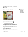
Checking or Replacing the
Te m p e r a t u r e S e n s o r
IMPORTANT: Always refer
to the wiring diagrams
that came with your
chiller to locate specific
electrical components.
Illustrations in the User
Guide are intended to be
representative only.
The EarthSmart ECM Series Chiller uses a RTD sensor to monitor the temperature
of the process coolant.
Typical location of
the RTD at the
chiller’s evaporator.
To check or replace an RTD sensor:
1 Disconnect and/or lockout the main power supply.
2 Locate the RTD sensor.
3 Check the sensor’s position and condition. Temperature readings will be
incorrect if the sensor is touching the wall of a pipe or if the sensor or wiring is
damaged. Sensor wires should be attached to the appropriate connection points
on the chiller’s control center.
Replacement RTDs are
available from Conair.
Contact Conair Parts
(800) 458 1960
From outside of the
United States, call:
(814) 437 6861
4 To check with ohm meter, measure the resistance across the RTDs. The
resistance should be approximately 110 ohm at room temperature. See
Appendix F entitled, RTD Resistance Chart.
5 Remove the sensor from its housing using an appropriately-sized wrench.
6 Inspect the sensor for cleanliness. Replace if necessary with another sensor of
the same rating.
7 Replace the RTD, by wrapping the its threads with Teflon tape or pipe dope.
8 Re-insert the RTD into its housing, start by hand until its threads engage.
Tighten with an appropriately-sized wrench, do not over tighten.
6 - 8 l Tr o u b l e s h o o t i n g
Checking or Resetting the Circuit
Breakers
The EarthSmart ECM Series Chiller uses electrical circuit breaker to protect the
chiller from overloads or improper operating conditions.
IMPORTANT: Always refer
to the wiring diagrams
that came with your
chiller to locate specific
electrical components.
Illustrations in the User
Guide are intended to be
representative only.
Circuit Breakers
To check or reset the chiller’s circuit breakers:
1 Disconnect and lockout the main power supply.
2 Remove the chiller’s top lid, by first removing both side panels and then the
four (4) retaining bolts that secure the chiller’s top lid.
3 Locate the appropriate circuit breaker(s), located behind the chiller’s
control panel. See the wiring diagrams that came with your chiller.
4 Check the circuit breaker(s) position and condition. The chiller will not
operate correctly if one or more circuit breakers have been tripped (facing
down).
5 Reset the circuit breaker(s), if necessary.
6 Replace the chiller’s side panels and then the top lid by replacing the four
(4) retaining bolts.
7 Reapply main power.
Tr o u b l e s h o o t i n g l 6 - 9
Additional manuals and prints for
your Conair equipment may be
ordered through the Customer
Service or Parts Department for a
nominal fee. Most manuals can
be downloaded free of charge
from the product section of the
Conair website.
www.conairgroup.com
We ’ r e H e r e t o H e l p
Conair has made the largest investment in customer support in the plastics industry. Our service experts are available to help with any problem you might have
installing and operating your equipment. Your Conair sales representative also
can help analyze the nature of your problem, assuring that it did not result from
misapplication or improper use.
How to Contact Customer Service
To contact Customer Service personnel, call:
PARTS & SERVICE
5
04
80
✐
19
60
43
76
861
US
8
INTERNATIONAL
4
81
+1
NOTE: Normal operating hours are 8:00 am - 5:00 pm (EST). After hours emergency
service is available at the same phone number.
You can commission Conair service personnel to provide on-site service by
contacting the Customer Service Department.
B e f o r e Yo u C a l l . . .
If you do have a problem, please complete the following checklist before
calling Conair:
❒ Make sure you have all model, control type and serial numbers from the serial
tag, and parts list numbers for your particular equipment. Service personnel will
need this information to assist you..
❒ Make sure power is supplied to the equipment.
❒ Make sure that all connectors and wires within and between control systems
and related components have been installed correctly.
❒ Check the troubleshooting guide of this manual for a solution.
❒ Thoroughly examine the instruction manual(s) for associated equipment, especially controls. Each manual may have its own troubleshooting guide to help you.
❒ Check that the equipment has been operated as described in this manual.
A-1 l Appendix
❒ Check accompanying schematic drawings for information on special considerations.
Equipment Guarantee
Conair guarantees the machinery and equipment on this order, for a period as
defined in the quotation from date of shipment, against defects in material and
workmanship under the normal use and service for which it was recommended
(except for parts that are typically replaced after normal usage, such as filters,
liner plates, etc.). Conair’s guarantee is limited to replacing, at our option, the part
or parts determined by us to be defective after examination. The customer assumes
the cost of transportation of the part or parts to and from the factory.
Pe r f o r m a n c e Wa r r a n t y
Conair warrants that this equipment will perform at or above the ratings stated in
specific quotations covering the equipment or as detailed in engineering specifications, provided the equipment is applied, installed, operated and maintained in the
recommended manner as outlined in our quotation or specifications.
Should performance not meet warranted levels, Conair at its discretion will
exercise one of the following options:
• Inspect the equipment and perform alterations or adjustments to satisfy
performance claims. (Charges for such inspections and corrections will be
waived unless failure to meet warranty is due to misapplication, improper
installation, poor maintenance practices or improper operation.)
• Replace the original equipment with other Conair equipment that will meet
original performance claims at no extra cost to the customer.
• Refund the invoiced cost to the customer. Credit is subject to prior notice by the
customer at which time a Return Goods Authorization Number (RGA) will be
issued by Conair’s Service Department. Returned equipment must be well crated
and in proper operating condition, including all parts. Returns must be prepaid.
Purchaser must notify Conair in writing of any claim and provide a customer receipt
and other evidence that a claim is being made.
Wa r r a n t y L i m i t a t i o n s
Except for the Equipment Guarantee and Performance Warranty stated
above, Conair disclaims all other warranties with respect to the equipment,
express or implied, arising by operation of law, course of dealing, usage of
trade or otherwise, including but not limited to the implied warranties of
merchantability and fitness for a particular purpose.
Appendix l A-2
Safety Adjustments
✐
NOTE: For chiller operation
below 45°F {7.2°C}, the
chiller’s control must be
configured properly. Contact
Conair Service.
IMPORTANT: A correct mixture of
glycol and water must be used as
process coolant for operation below
To ensure safe and efficient operation at lower setpoints, adjustments of the
low pressure switch from factory settings is required. The table below lists the
appropriate settings.
Operating
Temperature
Low
Cut In
Low
Cut Out
45°F
40°F
35°F
30°F
35#
30#
25#
20#
25#
20#
16#
12#
The low pressure switch serves as the mainline defense against freezing. It
shuts down the chiller if the coolant temperature ever decreases to its setting.
45°F {7.2°C}. See Installation sec-
tion entitled, Filling the Chiller.
To adjust a mechanical low pressure switch:
1 Disconnect and lockout the main power supply.
2 Remove the chiller’s right-side panel, as viewed from the control.
3 Locate the low pressure switch within the top portion of the chiller’s cabinet.
CAUTION: At any setpoint, the
possibility of freezing exists and
it is the operator’s responsibility
to take necessary action to
prevent freezing at all times.
✐
NOTE: The high and low pres-
4 Turn the low pressure cut-in and cut-out adjustment screws found on the
top of the low pressure switch, according the operating temperature located
on the chart above.
sure switches are enclosed
inside the same module.
Cut-out adjustment
Cut-in adjustment
5 Replace the chiller’s right-side panel and reapply main power.
B-1 l Appendix
Wa t e r Q u a l i t y C o n t r o l
Insufficient or improper water treatment can damage the EarthSmart ECM Chiller.
A certified water treatment specialist should be consulted for your particular
application. It is the owner’s responsibility to prevent damage from foreign
material or inadequate water treatment.
The two main points to consider for water treatment in chillers are:
• Corrosion
• Organism growth
Proper chemical treatment will control pH levels and algae growth.
Appendix l C-1
Chiller Capacity and Derate Chart
✐
NOTE: For chiller operation
below 45°F {7.2°C}, the
chiller’s control must be
Ambient conditions affect air-cooled chiller operation and capacity. Standard
rating is at 95°F {35°C} entering air temperature. For ambient air conditions
greater than 95°F {35°C}, chiller derating will occur.
configured properly. Contact
Conair Service.
Standard chiller rating is 50°F {10°C} leaving water. For all other temperature
settings, output tonnage is altered as follows:
IMPORTANT: A correct mixture of
Output
Temperature °F {°C}
glycol and water must be used as
Full Available %
Capacity
process coolant for operation below
60°F {15.5°C}
50°F {10°C}
45°F {7.2°C}
40°F {4.4°C}
35°F {1.6°C}
30°F {-1.1°C}
25°F {-3.8°C}
20°F {-6.7°C}
45°F {7.2°C}. See Installation sec-
tion entitled, Filling the Chiller.
105%
100%
90%
80%
70%
60%
50%
40%
If operation of the chiller is less than 45°F {7.2°C}, a glycol and water mixture
is required. See Operation section entitled, Filling the Chiller.
✐
NOTE: Models must be positioned so that the condenser air inlet is no warmer than 95°F
{35°C} and the condenser air outlet is not blocked or restricted in any way.
✐
NOTE: Locate models away from heat producing equipment. These items will affect ambient air conditions and the performance of the chiller.
D-1 l Appendix
P r e s s u r e - Te m p e r a t u r e C h a r t f o r
R-134A Refrigerant
Refrigerant Pressure (PSIG)
5
10
15
20
25
30
35
40
45
50
55
60
65
70
75
80
85
90
95
100
105
110
115
120
125
130
135
140
145
150
155
160
170
180
190
200
210
220
230
Saturated Temperature
-3°F {-19.4°C}
7°F {-13.9°C}
15°F {-9.4°C}
22°F {-5.5°C}
29°F {-1.6°C}
35°F {1.6°C}
40°F {4.4°C}
45°F {7.2°C}
50°F {10°C}
54°F {12.2°C}
58°F {14.4°C}
62°F {16.7°C}
66°F {18.9°C}
69°F {20.5°C}
73°F {22.7°C}
76°F {24.4°C}
79°F {26.1°C}
82°F {27.7°C}
85°F {29.4°C}
88°F {31.1°C}
90°F {32.2°C}
93°F {33.8°C}
96°F {35.5°C}
98°F {36.6°C}
100°F {37.7°C}
103°F {39.4°C}
105°F {40.5°C}
107°F {41.6°C}
109°F {42.7°C}
112°F {44.4°C}
114°F {45.5°C}
116°F {46.6°C}
120°F {48.8°C}
123°F {50.5°C}
127°F {52.7°C}
130°F {54.4°C}
134°F {56.6°C}
137°F {58.3°C}
140°F {60°C}
✐
NOTE: These pressure/
temperature relationships are in
an “At-Rest”, saturated
condition. For example, if the
unit has been in a warehouse at
40°F {4.4°C} and it is brought
to a room where it is 80°F
{26.7°C}, it may require a few
hours for the unit to warm and
the pressure to rise to the
surrounding ambient conditions.
Appendix l E-1
RT D R e s i s t a n c e C h a r t
You can use the following chart to determine if you need to replace your RTD.
F-1 l Appendix
Overhead Plumbing Details
Overhead piping installations above process connections require installing a check
valve in the “To Process” line and a 12 inch {305 mm} riser with a check valve and
vacuum break in the “From Process” line to prevent siphoning when shutting down
the chiller. Install a vent tube at 12 inches {305 mm} above the highest system point
to prevent over pressurization. Maximum height of piping above process connections
is 25 ft {7.6 m}.
Internal vent; 1 ft above
highest water level
vacuum break
check valve
12 in. riser
From process
To process
back view
Appendix l G-1
H-1 l Appendix
8.00
1CAB
1PL
2PL
3PL
1SW
7.88
4PL
5PL
1TC
6PL
2CAB
7PL
1
4.04
2
1TB
1TC
1ENC
2ENC
2
2
2
3
4
6
7
7
8
9
10
9.00
1GB
2CB 1CB
1SW
Electrical Schematic
Control Setup
1/32 DIN Watlow SD controller Setup Sheet
Enter the following parameters
Menu
Set Up Page
up & down for
3 seconds
Parameter
Sen
C-F
S.dec
IS.en
SP.Lo
SP.hi
Ftr.e
Flt.r
Ot1
Ctr1
Ftb1
PL 1
PSL1
PSH1
nLF1
Ot2
hys2
Lgc2
Lat2
dSP2
ACLF
Unit
I.Err
FAIL
Man
dSP
rP
LOC
Description
Input sensor type
Temperature Units (degrees)
Temperature Decimal Places
Infosense
Set Point Low Limit
Set Poing High Limit
Input Filter
Filter value - Seconds
Output 1 function
Control Method 1
Cycle time 1
Power Limit 1
Output Power Limit Sacle Low 1
Output Power Limit Sacle High 1
Output Non-Linear Function 1
Output 2 Function - SP devaition
Alarm Hysteresis 2
Alarm relay state on alarm - open
Alarm 2 latching
Alarm 2 Message
AC line frequency
Units of Measurement
Input error latching
Input Error Failure Mode
Manual Error Level
Active Displays
Ramping Mode
Security Lockout
Programming
Adv and INF keys 6 seconds
P1
P2
P3
P4
P5
P6
Temperature Units - C-F
Low Temp Dev. alarm - A2.Lo
High Temp dev Alarm - A2.HI
Proportional Band Hot Gas - pb.ht
Intergral Hot Gas - It.ht
Derivative - dE.ht
Setting
RTD
F
0
no
40.0
65
Both
5
heat
ftb
10
100%
0%
90%
Off
dE.AL
1.5F
Al o
nLat
on
60
SI
nLat
bPLS
0%
nor
off
3
F
-4
20
3
3.4
0.1
Appendix l I-1
PSL
1
FROM PROCESS
TO PROCESS
DESCRIPTION
PSV SET AT
50 PSIG
1
2"
1
4"
1
4"
VENT 3/8"
1
2"
25 PSIG ON FALL
35 PSIG ON RISE
(1/4" gauge port)
CUT OUT AT
CUT IN AT
1/2" FILL/DRAIN
(HOSE BIBB)
02 DEW REVISED
01 WDH PROTOTYPE
REV BY
J-1 l Appendix
LEVEL
11/27/07 DEW
09/12/07 DEW
APP
DATE
3
8"
ECN
OD TUBE
10 GALLON
WATER
TANK
BYPASS
3
8"
3
8"
DXF
FS
1
(1/4" schraeder valve)
3
8"
3
8"
EVAPORATOR
PSV SET AT
250 PSIG
3
8"
3/8" OD TUBE
OD TUBE
1
4"
1
8"
1
4"
FPT
TE
1
3
8"
TO PROCESS
TEMP
PI
1
3
8"
OD TUBE
TAHH
1
0-150 PSI GAGE
TIC
1
TALL
1
OD TUBE
S
RANGE= 40 TO 65 °F
1
4"
CONDENSER FAN
OD TUBE
TXV
1
4"
PSH
2
PSH
1
SIGHT GLASS
(1/4" schraeder valve)
PRESSURE TESTING, EVACUATION AND REFRIGERANT CHARGING OF THE
CHILLER SHALL BE PERFORMED PER SECTION 3 OF THE CONAIR CHILLER
TEST STAND MANUAL.
FORMED SHEETMETAL:
ANGLES:
FINISH:
FRACTIONS
DECIMAL MACHINING:
XX:
XXX:
± 0.015
± 0.005
± 0.015
± 1/2 °
125
± 1/32
1 OF 1
DRAWN BY:
SHEET:
WJS
DWG NO.:
ECA.5 P&ID
DATE:
04/02/08
The Conair Group Inc.
One Conair Drive
Pittsburgh, PA 15202
PORTABLE CHILLER,AIRCOOLED
SINGLE PUMP, ENHANCED
VAPOR CHARGING & EVACUATION VALVE ON SUCTION LINE NOT REQUIRED
IF SUCTION VALVE HAS A SERVICE PORT.
SV-2 TO BE LOCATED ABOVE COMPRESSOR DISCHARGE.
125 PSIG ON FALL
200 PSIG ON RISE
CUT OUT AT
230 PSIG
ON RISE MANUAL RESET
CUT OUT AT
CUT IN AT
END OF CONDENSING UNIT
REFRIGERATION ISOLATION VALVE
LINE SIZE REDUCTION
INLINE INSTRUMENT w/ TAG NUMBER
STRAINER
Hand Valve
Thermostatic Expansion Valve
FILTER/DRYER
OD TUBE
SV-1
LIQUID LINE VALVE
1
4"
RECEIVER
XX
X
LEGEND
PRESSURE RELIEF VALVE
SOLENOID VALVE
K OR L-TYPE COPPER TUBING TO BE USED FOR REFRIGERANT PIPING
S
MACHINING TOLERANCES:
4.
3.
2.
1.
NOTES:
SV-2
HOT GAS BYPASS
SEE NOTE 3
1
4"
S
01
REV:
ACAD
Plumbing Schematic