1
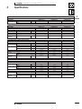
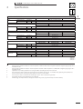
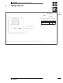
FDYMP-L7
Concealed Ceiling Unit
Split
Sky Air
air conditioning systems
technical data
Split - Sky Air
ISO14001 assures an effective environmental
management system in order to help protect
human health and the environment from the potential
impact of our activities, products and services and to
assist in maintaining and improving the quality of
the environment
Daikin Europe N.V. is approved by LRQA for its Quality
Management System in accordance with the ISO9001
standard. ISO9001 pertains to quality assurance regarding
design, development, manufacturing as well as to services
related to the product.
Daikin units comply with the European
regulations that guarantee the safety of
the product.
Daikin Europe N.V. is participating
in the EUROVENT Certification Programme.
Products are as listed in the EUROVENT
Directory of Certified Products.
Zandvoordestraat 300
B - 8400 Ostend Belgium
Internet: http://www.daikineurope.com
EEDE03-1/2 • 03/2003
Prepared in Belgium by Goekint Graphics
Specifications are subject to change without prior notice.
• Concealed Ceiling Unit • R-407C • FDYMP71-125L7V1/W1
TABLE OF CONTENTS
FDYMP-L
1
Features
2
Specifications
.................................................................................
.......................................................................
2
3
Nominal capacity, capacity steps and nominal input
Technical specifications
3
Dimensional drawings
.....................................................
6
4
Piping diagrams
..................................................................
7
5
Wiring diagrams
.................................................................
8
6
Sound level
..........................................................................
9
Sound level data
Sound pressure spectrum
Sound power spectrum
7
Fan characteristics
..............................................................
11
8
Accessories
..........................................................................
12
Optional accessories
9
Control systems
..................................................................
13
10
Center of gravity
................................................................
14
11
Safety device settings
12
Installation
......................................................
14
............................................................................
15
* For capacity tables, please refer to part II: outdoor units
• Split - Sky Air • Indoor Units
1
• Concealed Ceiling Unit • R-407C • FDYMP71-125L7V1/W1
1
1
1
Features
+ Lightweight and compact: the depth of the unit is just 279mm
for all capacity sizes.
+ Both discharge and suction ducts can be easily connected via
flanges on the unit.
+ The air filter is easily accessible from underneath, even after the
installation of the ducts.
+ Silent in operation both indoors and outdoors: sound pressure
for the indoor units as low as 37dB(A)
+ Numerous optional control facilities
1
8 q x 7
Optional
6 ! 2 6 4
2 steps
2
• Split - Sky Air • Indoor Units
• Concealed Ceiling Unit • R-407C • FDYMP71-125L7V1/W1
2
Specifications
1
2
NOMINAL CAPACITY and NOMINAL INPUT
For indoor units only:
INDOOR UNITS
NOMINAL INPUT
Cooling
Heating
kW
kW
For combination indoor + outdoor units (air cooled):
INDOOR UNITS
OUTDOOR UNITS
NOMINAL CAPACITY (3)
Cooling
NOMINAL INPUT
Cooling
EER
ENERGY LABEL
Cooling
ANNUAL ENERGY
Cooling
CONSUMPTION
For combination indoor + outdoor units (air cooled):
INDOOR UNITS
OUTDOOR UNITS
NOMINAL CAPACITY (3)
Cooling
Heating
NOMINAL INPUT
Cooling
Heating
EER
COP
ENERGY LABEL
Cooling
Heating
ANNUAL ENERGY
Cooling
CONSUMPTION
For combination indoor + outdoor units (air cooled):
INDOOR UNITS
OUTDOOR UNITS
NOMINAL CAPACITY (3)
Cooling
Heating
NOMINAL INPUT
Cooling
Heating
EER
COP
ENERGY LABEL
Cooling
Heating
ANNUAL ENERGY
Cooling
CONSUMPTION
kW
kW
kWh
kW
kW
kW
kW
kWh
kW
kW
kW
kW
kWh
• Split - Sky Air • Indoor Units
FDYMP71L7V1
-
FDYMP100L7V1
-
FDYMP125L7V1
-
FDYMP71L7V1
RP71L7V1/W1-RP71B7T1
7.10
2.60/2.66
2.67/2.73
D/D
1,330/1,300
FDYMP100L7V1
RP100L7V1/W1-RP100B7T1
10.00
3.75/3.72
2.66/2.69
D/D
1,875/1,860
FDYMP125L7V1
RP125L7W1-RP125B7T1
12.20
4.62
2.64
D/D
2.310
FDYMP71L7V1
RYP71L7V1/W1
7.10
8.00
2.61/2.55
2.48/2.43
2.72/2.78
3.21/3.29
D/D
C/C
1,305/1,275
FDYMP100L7V1
RYP100L7V1/W1
10.00
11.00
3.68/3.65
3.75/3.72
2.72/2.74
2.93/2.96
D/D
D/D
1,840/1,825
FDYMP125L7V1
RYP125L7W1
12.20
14.50
4.55
4.34
2.68
3.34
D
C
2.275
FDYMP71L7V1
RYEP71L7V1/W1
7.10
8.00
2.70/2.63
2.57/2.50
2.63/2.70
3.11/3.20
D/D
D/C
1,350/1,315
FDYMP100L7V1
RYEP100L7V1/W1
10.00
11.00
3.69/3.79
3.79/3.89
2.71/2.64
2.90/2.83
D/D
D/D
1,845/1,895
FDYMP125L7V1
RYEP125L7W1
12.20
14.50
4.55
4.34
2.68
3.34
D
C
2.275
3
• Concealed Ceiling Unit • R-407C • FDYMP71-125L7V1/W1
2
Specifications
1
2
TECHNICAL SPECIFICATIONS
For indoor units only:
INDOOR UNITS
DIMENSIONS
Unit
WEIGHT
MATERIAL
SOUND LEVEL
FAN
HEAT EXCHANGER
AIR FILTER
TEMPERATURE CONTROL
PIPING CONNECTIONS
4
Unit
Unit
Sound pressure
(cooling/heating) (1)
Sound power
(cooling only) (2)
Air flow rate
(cooling/heating)
Speed
Type
Qty x motor output
External static pressure (H-L)
Drive
Type
Rows x stages x fin pitch
Face area
INSULATION MATERIAL
Heat insulation
Sound absorbing insulation
For outdoor units
Pair application
Twin application
H
W
D
mm
mm
mm
kg
FDYMP71L7V1
987
38.1
high
low
high
dB(A)
dB(A)
dB(A)
37/37
33/33
63
high
low
steps
m3/min
m3/min
19/19
14/14
W
Pa
1 x 130
mm
m2
liquid
gas
drain
drain
mm
mm
mm
mm
FDYMP100L7V1
279
0.226
φ15.9
I.D. φ25
O.D. φ32
FDYMP125L7V1
1,387
750
48.6
Painted galvanised steel plate
39/39
34/34
65
41/41
35/35
66
27/27
20/20
3 steps
Sirocco fan
1 x 155
100 - 50
Direct drive
Fin rhombus type, J7 Hi-XA tube
3 x 14 x 1.75
35/35
24/24
1 x 225
0.344
Resin net
Computerised control
φ9.52
I.D. φ25
O.D. φ32
Both liquid and gas pipes
Felt
φ19.1
See chapter RP-L7/B7/RYP-L/RYEP-L7
See chapter RP-L7/B7/RYP-L7/RYEP-L7
• Split - Sky Air • Indoor Units
I.D. φ25
O.D. φ32
• Concealed Ceiling Unit • R-407C • FDYMP71-125L7V1/W1
2
Specifications
1
2
ELECTRICAL SPECIFICATIONS
For indoor units only:
CURRENT
Nominal running current
Max. running current
Nominal running current
Max. running current
Starting current
FDYMP100L7V1
See chapter RP-L7/B7/RYP-L7/RYEP-L7
See chapter RP-L7/B7/RYP-L7/RYEP-L7
FDYMP125L7V1
FDYMP71L7V1
RP71L7V1/W1-RP71B7T1
FDYMP100L7V1
RP100L7V1/W1-RP100B7T1
See chapter RP-L7/B7
See chapter RP-L7/B7
See chapter RP-L7/B7
FDYMP125L7V1
RP125L7W1-RP125B7T1
FDYMP71L7V1
RYP71L7V1/W1
FDYMP100L7V1
RYP100L7V1/W1
See chapter RYP-L7
See chapter RYP-L7
See chapter RYP-L7
FDYMP125L7V1
RYP125L7W1
FDYMP71L7V1
RYEP71L7V1/W1
FDYMP100L7V1
RYEP100L7V1/W1
See chapter RYEP-L7
See chapter RYEP-L7
See chapter RYEP-L7
FDYMP125L7V1
RYEP125L7W1
FDYMP71L7V1
V1
1∼
50
230
FDYMP100L7V1
V1
1∼
50
230
FDYMP125L7V1
V1
1∼
50
230
cooling/heating A
cooling/heating A
For combination indoor units + outdoor units:
CURRENT
FDYMP71L7V1
cooling
cooling
cooling
A
A
A
For combination indoor units + outdoor units:
CURRENT
Nominal running current
Max. running current
Starting current
cooling/heating A
cooling/heating A
cooling/heating A
For combination indoor units + outdoor units:
CURRENT
Nominal running current
Max. running current
Starting current
For indoor units only:
POWER SUPPLY
NOMINAL DISTRIBUTION
Phase
SYSTEM VOLTAGE
Frequency
Voltage
cooling/heating A
cooling/heating A
cooling/heating A
Hz
V
3TW25041-1
3TW25051-1
3TW25061-1
NOTES
1
Nominal cooling capacities are based on: indoor temperature 27°CDB/19°CWB * outdoor temperature 35°CDB * refrigerant piping length: 7.5m *
level difference: 0m.
2
Nominal heating capacities are based on: indoor temperature: 20°CDB * outdoor temperature: 7°CDB/6°CWB * refrigerant piping length: 7.5m *
level difference 0m.
3
Capacities are net, including a deduction for cooling (an addition for heating) for indoor fan motor heat.
4
The sound pressure level is measured via a microphone at 1.5m distance from the unit. It is a relative value, depending on the distance and
acoustic environment. For measuring conditions: please refer to item 6 of this chapter.
5
The sound power level is an absolute value indicating the ’’power’’ which a sound source generates.
6
Energy label: scale from A (most efficient) to G (less efficient).
7
Annual energy consumption: based on average use of 500 running hours per year at full load (= nominal conditions).
• Split - Sky Air • Indoor Units
5
• Concealed Ceiling Unit • R-407C • FDYMP71-125L7V1/W1
3
Dimensional drawings
1
FDYMP71-100L7
1
2
3
4
5
6
7
8
9
668 (Suspension position)
Liquid pipe connection J9.52 Flare connection
Gas pipe connectionJ A Flare connection
Remote control wiring connection
Power supply connection
Drain pipe connection VP25 (O.D. J 32, I.D. J 25)
Air filter
Air suction side
Air discharge side
Name plate
view B
960 (Suspension position)
view A
300 mm or more
Suspension bolt
(Installation space)
3
300 mm or more
(Service space)
Notes:
1. Refer to ’outlook drawing for installing optional accessories’ when installing optional accessories.
2. For maintenance of the air filter, it is necessary to provide a service access panel according to the
installation method. (Refer to the ’filter installation method’ drawing)
Model
FDYMP71L7V1
FDYMP100L7V1
A
15.90
19.10
3TW25044-1
FDYMP125L7
668 (Suspension position)
1
2
3
4
5
6
7
8
9
Liquid pipe connection J9.52 Flare connection
Gas pipe connection J19.10 Flare connection
Remote control wiring connection
Power supply connection
Drain pipe connection VP25 (O.D. J32, I.D. J25)
Air filter
Air suction side
Air discharge side
Name plate
1360 (Suspension position)
view A
300 mm or more
(Installation space)
Suspension bolt
(Service space)
Notes:
1. Refer to ’outlook drawing for installing optional accessories’ when installing optional accessories.
2. For maintenance of the air filter, it is necessary to provide a service access panel according to the
installation method. (Refer to the ’filter installation method’ drawing)
view B
6
• Split - Sky Air • Indoor Units
2TW25064-1
• Concealed Ceiling Unit • R-407C • FDYMP71-125L7V1/W1
4
Piping diagrams
1
FDYMP71-125L7
4
Refrigerant flow
Cooling
Heating
Heat exchanger
Refrigerant pipe connection port diameters
Model
FDYMP71L7V1
FDYMP100L7V1
FDYMP125L7V1
Gas
J15.9
Liquid
J9.52
J19.1
J9.52
Liquid pipe connection port
Filter
Gas pipe connection port
O Check valve L Flare connection M Screw connection N Flange connection Z Pinched pipe P Spinned pipe
3TW25045-1
• Split - Sky Air • Indoor Units
7
• Concealed Ceiling Unit • R-407C • FDYMP71-125L7V1/W1
5
Wiring diagrams
1
5
FDYMP71∼125L7
Outdoor
Indoor
Notes
Wired remote
control
1. When using the central remote control, see manual
for connection to the unit.
2. The infrared remote control model varies according to
the combination system.
See technical data and catalogs before connecting.
Fan operation
Details of wired remote control
(optional accessory)
g Field wiring D Terminal
a : Connector
c
: Wire clamp
b
: Protective earth (screw)
Colours
BLK: Black/ PPL: purple/ BLU: Blue/
WHT: White/ RED: Red/ GRN: green/
GRY: grey/ YLW:Yellow
A1P
T1R
Printed circuit board
Power supply transformer (transformer 220-240V/
218V)
C1R
Capacitor (fan)
F1T
Thermal fuse (152°C) (M1F embedded)
HAP
Light emitting diode (service monitor green)
M1F
Motor (fan)
R1T
Thermistor (air)
R2T
Thermistor (coil)
RyF1∼3 Magnetic relay (fan)
Switch box
SS1
Selector switch (emergency)
X1M
Terminal strip
X2M
Terminal strip
RC
Signal receiver circuit
TC
Signal transmission circuit
Group control jumper
J1
Jumper for ’’Master/slave’’ determination
Cautions for servicing
With the power on, troubles can be monitored on the
remote controller or the LED on the PC board of the
indoor unit.
Troubleshooting with the display on the liquid
crystal of the remote controller.
When the operation stops due to trouble, the
operation lamp flashes, ’’b’’ and the error codes are
indicated on the liquid crystal display. In this case,
diagnose the fault contents by refering to the table on
the right. In case of group control, the unit number is
displayed so that the indoor unit with the trouble can
be recognized (see note 2).
j
1 Press the INSPECTION/TEST OPERATION button ’’b’’ is
displayed and ’’O’’ flashes.
j
2 Press the PROGRAMMING TIME button and find the
unit number which stopped due to trouble.
Number of beeps:
3 short beeps ... Perform all the following operations
3 and j
6
1 short beep ... Perform j
1 long beep ... No trouble
j
3 Press the operation mode selector button and upper
figure of the error code flashes.
j
4 Continue pressing the PROGRAMMING TIME button
until it makes 2 short beeps and find the upper code.
j
5 Press the OPERATION SELECTOR button and lower
figure of the error code flashes.
j
6 Continue pressing the PROGRAMMING TIME button
until it makes a long beep and find the lower code. A
long beep indicates the error code.
Error
codes
A1
A6
AJ
C4
C9
CJ
E0
E1
E3
E4
E9
F3
H3
H4
H9
J3
J5
J6
PJ
U0
U1
U4
U5
UF
Wired remote control
BS1
On/Off button
BS2
Timer mode start/stop button
BS3,BS8 Programming time button
BS4,BS9 Temperature setting button
BS6
Operation mode selector button
BS7
Timer on/off button
BS11
Fan speed control button
BS12
Inspection/test operation button
BS14
Filter sign reset button
Malfunction
Indoor unit’s PC board
Indoor fan motor overloaded, overcurrent or
locked
Type set error (indoor unit)
compressor operation
Terminals for operation
indicator
Adapter for wiring
LED1
Light emitting diode (service monitor red)
LCD
Liquid crystal display (LCD)
SS1
Selector switch (main/sub)
Adapter for wiring
RyC,RyF Magnetic relay
Connector for optional parts
X33A
Connector (adapter for wiring)
X35A
Connector (group control adapter)
X40A
Connector (remote ON/OFF forced OFF)
Remarks
Capacity data is wrongly preset or there is
nothing programmed in the data hold IC.
Sensor for heat exchanger temperature (indoor)
Sensor for suction air temperature (indoor)
Sensor for remote controller
The remote controller thermistor does not work,
but the system thermo run is possible.
Action of safety device (outdoor unit)
Outdoor unit’s PC board
Abnormal high pressure (outdoor unit)
Abnormal low pressure (outdoor unit)
Electronic expansion valve (outdoor unit)
Abnormal discharge pipe temperature (outdoor
unit)
High pressure switch defect (outdoor unit)
Low pressure switch defect (outdoor unit)
Outdoor air thermistor
(See note 3)
Discharge pipe thermistor (outdoor unit)
Suction pipe thermistor (outdoor unit)
Heat exchanger thermistor (outdoor unit)
(See note 3)
Type set error (outdoor unit)
Capacity data is wrongly preset or there is
nothing programmed in the data hold IC.
Abnormal suction pipe temperature (outdoor
unit)
Reverse phase
Reverse 2 of the 3 lead wires
Transmission error (indoor unit - outdoor unit) Transmission indoor - outdoor is improper
Transmission error (indoor unit - remote con- Transmission indoor-remote contr. Is improper if
troller)
group control: check ’master-slave jumper’.
Miss wiring
Field wiring is not correct
For the white error codes on a black background, be
sure to check and repair, though system may be
operated without displaying ’’b.
Notes:
1. Press the INSPECTION / TEST OPERATION button.
’’b starts flashing.
2. Keep down the ON/OFF button for 5 seconds or
longer in the inspection mode, and the above
trouble history disappears, after the trouble code
goes on and off twice, followed by the code ’’00’’
(normal). The display changes from the inspection
mode to the normal mode.
3. Equipment operation in response to errors will vary
according to the model.
Troubleshooting with the LED on the indoor PC
board.
The following checking can be made with the service
monitor LED (green) (normal when flashing).
p: LED on s: LED off q: LED flashing
Microcomputer
normal monitor
Description
HAP
q
Normal -> Outdoor unit
p
Indoor PC board error (see note)
s
Power supply trouble or PC board error (see note)
NOTE:
Cut off the power and wait for 5 seconds or longer.
Turn on the power again and see if the LED is the
same state.
2TW25046-1A
8
• Split - Sky Air • Indoor Units
• Concealed Ceiling Unit • R-407C • FDYMP71-125L7V1/W1
6
6-1
Sound level
Sound level data
1
6
Sound pressure level
230V, 50Hz
Model
Cooling/Heating
FDYMP71L7V1
Measuring location
High
Low
37/37
33/33
Location of microphone
Unit
Suction
FDYMP100L7V1
39/39
Sound power level (H)
(cooling)
6-1
63
Discharge
34/34
65
Microphone
FDYMP125L7V1
6-2
41/41
35/35
66
Sound pressure spectrum
Sound pressure level (dB)
FDYMP100L7
Sound pressure level (dB)
FDYMP71L7
Octave band center frequency (Hz)
Octave band center frequency (Hz)
3TW25047-1
3TW25057-1
Sound pressure level (dB)
FDYMP125L7
Legend
High speed
Low speed
NOTES
Octave band center frequency (Hz)
1
2
3
4
Data is valid at free field condition
Data is valid at low ESP operation condition. (50 Pa AT 230V)
dBA = A-weighted sound pressure level (A-scale according to IEC)
Reference acoustic pressure 0dB = 20µPa
3TW25067-1
• Split - Sky Air • Indoor Units
9
• Concealed Ceiling Unit • R-407C • FDYMP71-125L7V1/W1
6
Sound power spectrum
FDYMP71L7
FDYMP100L7
Sound power level (dB)
6-3
Sound level
Sound power level (dB)
1
6
6-3
Octave band center frequency (Hz)
Octave band center frequency (Hz)
3TW25047-2
3TW25057-2
NOTES
FDYMP125L7
Sound power level (dB)
1
2
3
Octave band center frequency (Hz)
3TW25067-2
10
• Split - Sky Air • Indoor Units
Data is valid at low ESP operation high tap condition. (50Pa at 230V)
dB(A) = A-weighted sound power level (A-scale according to IEC)
Measured in duct according to ISO 9614
• Concealed Ceiling Unit • R-407C • FDYMP71-125L7V1/W1
7
Fan characteristics
1
FDYMP71L7
7
ESP (Pa)
Fan curve 71 class motor
Air flow (m3/min)
3TW25048-1
FDYMP100L7
ESP (Pa)
Fan curve 100 class motor
Air flow (m3/min)
3TW25058-1
FDYMP125L7
ESP (Pa)
Fan curve 125 class motor
Air flow (m3/min)
• Split - Sky Air • Indoor Units
3TW25068-1
11
• Concealed Ceiling Unit • R-407C • FDYMP71-125L7V1/W1
1
8
8-1
8
8-1
Accessories
Optional accessories
Item
Remote control
Adapter for wiring (interlock for fresh air intake fan)
Adaptor for external ON/OFF and monitoring
Wiring adapte (electrical heater and hour meter
Installation box
Remote ON/OFF, forced OFF
Wired type
71-100-125 Class
BRC1D517
KRP1B59
KRP4A51
EKRP1B2
KRP1B947A
EKR0R0
3TW25049-4B
* Electrical heater and humidifier are field supply. The electrical heater should be installed in the discharge duct.
Wire specifications
Connector (White)
White
connect to indoor PCB (X40A)
connect to on/off switch
AWG24 0.22mm2 White
Operating method
ON*
Switch
Input
OFF
ON
Remote control
OFF
ON
Standard setting:
’forced off’
Unit
OFF
ON
Alternative
setting: ’on/off’
OFF
* Input ’ON’ = closed contact.
Forced off
On/off operation
Input ’on’ stops operation + disables control
Input off→on: starts operation, remote control is still enabled.
Input ’off’ enables control
Input on→off: stops operation, remote control is still enabled.
Selection of ’FORCED OFF’ and ’ON/OFF’ operation
Setting
Forced off
Mode NO
First code NO
Second code NO
12 (22)
1
01
On/off operation
02
4TW23941-1
12
• Split - Sky Air • Indoor Units
• Concealed Ceiling Unit • R-407C • FDYMP71-125L7V1/W1
9
9-1
Control systems
Wired remote control
1
9
BRC1D527
9-1
5 x 10 (Round end slit)
6.5 x 9 (Round end slit)
5 x 7 (Round end slit)
HoleJ5
Cover closed
Cover open
• Split - Sky Air • Indoor Units
3TW23651-2
13
• Concealed Ceiling Unit • R-407C • FDYMP71-125L7V1/W1
10
1
10
Center of gravity
FDYMP71-125L7
A
B
71 - 100 Class
Model
920
420
125 Class
1320
600
4TW25049-3
11
Safety device settings
FDYMP71-125L7
Model
FDYMP
Safety devices
Fan motor thermal fuse (°C)
71
100
125
152±2
152±2
152±2
3TW21009-2C
14
• Split - Sky Air • Indoor Units
• Concealed Ceiling Unit • R-407C • FDYMP71-125L7V1/W1
12
Installation instructions
Drain pipe work
Computerised control (forced OFF and ON/OFF
operation)
Indoor unit installation
1TW25049-2
1
12
15
• Split - Sky Air • Indoor Units
• Concealed Ceiling Unit • R-407C • FDYMP71-125L7V1/W1
How to clean the air filter
Service of switch box
Refrigerant piping work
Drain pipe work
Installation instructions
• Split - Sky Air • Indoor Units
Names and functions of parts
Selecting installation site
12
Preparations before installing
• Concealed Ceiling Unit • R-407C • FDYMP71-125L7V1/W1
12
Installation instructions
1
12
Filter fixing plate
Filter
Detail A
Scale 1/1
Only for 125 class
Only for 71 & 100 class
Filter holding plate
Only for 125 class
Detail B
Scale 1/1
3TW25044-2
NOTES
16
1
Filter must slide in the filter fixing plates (see detail A)
2
Filter holding plate must be mounted correct (see detail B)
• Split - Sky Air • Indoor Units