1
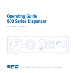
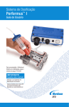
Ultra® 1400 Series
Dispenser
User’s Guide
Ultra 1400
Ultra 1415
™
Electronic pdf files of EFD manuals are also available at www.efd-inc.com/manuals.html
®
A NORDSON COMPANY
Introduction
Welcome to the Ultra 1400 Series User’s Guide, designed to help you maximize the usefulness
of your new dispenser.
Please spend a few minutes to become familiar with the controls and features. Follow our
recommended testing procedures. Review the helpful information we have included, which is
based on more than 30 years of industrial dispensing experience.
Most questions you will have are answered in this guide. However, if you need assistance,
please do not hesitate to contact EFD or your authorized EFD distributor.
n the USA, call 800-556-3484 between 8:30 a.m. and 5:30 p.m. Eastern time.
In Europe, call +44 (0) 1582 666334.
In Asia, call +86 (21) 3866 9166.
In all other areas, call your authorized EFD distributor or +1-401-431-7000.
The EFD Pledge
We pledge that you will be completely satisfied with our products. We endeavor to ensure that
every EFD product is produced to our no-compromise quality standards.
If you feel that you are not receiving all the support you require, or if you have any questions or
comments, I invite you to write or call me personally.
Our goal is to build not only the finest equipment and components, but also to build long-term
customer relationships founded on superb quality, service, value and trust.
Peter Lambert, President
2
Contents
Safety . . . . . . . . . . . . . . . . . . . . . . . . . . . . . . . . . . . . . . . . . . . . . . . . . . . . . . . . . . . . . . 4
Specifications. . . . . . . . . . . . . . . . . . . . . . . . . . . . . . . . . . . . . . . . . . . . . . . . . . . . . . . . . 6
Getting Started . . . . . . . . . . . . . . . . . . . . . . . . . . . . . . . . . . . . . . . . . . . . . . . . . . . . . . 7-9
Features and Controls . . . . . . . . . . . . . . . . . . . . . . . . . . . . . . . . . . . . . . . . . . . . . . . 1 0
Back Panel . . . . . . . . . . . . . . . . . . . . . . . . . . . . . . . . . . . . . . . . . . . . . . . . . . . . . . 12
Input/Output Connection . . . . . . . . . . . . . . . . . . . . . . . . . . . . . . . . . . . . . . . . . . . . 13
-
1
1
Vacuum Control . . . . . . . . . . . . . . . . . . . . . . . . . . . . . . . . . . . . . . . . . . . . . . . . . . . . . . 14
Filling the Syringe Barrel . . . . . . . . . . . . . . . . . . . . . . . . . . . . . . . . . . . . . . . . . . . . . . . . 15
Syringe Barrel Loaders. . . . . . . . . . . . . . . . . . . . . . . . . . . . . . . . . . . . . . . . . . . . . . 16
Test Procedures . . . . . . . . . . . . . . . . . . . . . . . . . . . . . . . . . . . . . . . . . . . . . . . . . . . 17-18
Schematic / Parts List. . . . . . . . . . . . . . . . . . . . . . . . . . . . . . . . . . . . . . . . . . . . . . . . . . 19
Troubleshooting . . . . . . . . . . . . . . . . . . . . . . . . . . . . . . . . . . . . . . . . . . . . . . . . . . . . . . 20
Helpful Hints. . . . . . . . . . . . . . . . . . . . . . . . . . . . . . . . . . . . . . . . . . . . . . . . . . . . . . . . . 21
Productivity Tools . . . . . . . . . . . . . . . . . . . . . . . . . . . . . . . . . . . . . . . . . . . . . . . . . . . . . 22
Warranty . . . . . . . . . . . . . . . . . . . . . . . . . . . . . . . . . . . . . . . . . . . . . . . . . . . . . Back Cover
This manual is for the express and sole use of EFD dispenser purchasers and users, and no portion of it may be reproduced in any form.
3
Safety
Introduction
Read and follow these safety instructions. Task- and equipment-specific warnings, cautions and
instructions are included in equipment documentation where appropriate.
Qualified Personnel
Equipment owners are responsible for making sure that EFD equipment is installed, operated and
serviced by qualified personnel. Qualified personnel are those employees or contractors who are trained
to safely perform their assigned tasks. They are familiar with all relevant safety rules and regulations,
and are physically capable of performing their assigned tasks.
Intended Use
Use of EFD equipment in ways other than those described in the documentation supplied with the
equipment may result in injury to persons or damage to property.
Some examples of unintended use of equipment include:
•
Using incompatible materials
•
Using incompatible or damaged parts
•
Making unauthorized modifications
•
Using unapproved auxiliary equipment
•
Removing or bypassing safety guards or
interlocks
•
Operating equipment in excess of maximum
ratings
Regulations and Approvals
Make sure all equipment is rated and approved for the environment in which it is used. Any approvals
obtained for EFD equipment will be voided if instructions for installation, operation and service are not
followed.
Personal Safety
To prevent injury follow these instructions.
4
•
Do not operate or service equipment unless you are qualified.
•
Do not operate equipment unless safety guards, doors or covers are intact and automatic interlocks
are operating properly. Do not bypass or disarm any safety devices.
•
If you receive even a slight electrical shock, shut down all electrical or equipment immediately.
Do not restart the equipment until the problem has been identified and corrected.
•
Obtain and read Material Safety Data Sheets (MSDS) for all materials used. Follow the manufacturer’s
instructions for safe handling and use of materials, and use recommended personal protection
devices.
•
To prevent injury, be aware of less-obvious dangers in the workplace that often cannot be completely
eliminated, such as hot surfaces, sharp edges, energized electrical circuits and moving parts that
cannot be enclosed or otherwise guarded for practical reasons.
•
This equipment is for indoor use only.
•
Use only the power cord provided with the unit. Contact EFD to purchase a replacement cord.
•
Always keep dispensing end of syringe barrel pointed away from your face and towards the work
piece. Store the syringe barrel in an appropriate holder when not in use.
Safety
Fire Safety
To avoid a fire or explosion, follow these instructions.
•
Shut down all equipment immediately if you notice static sparking or arcing. Do not restart the
equipment until the cause has been identified and corrected.
•
Do not smoke, weld, grind or use open flames where flammable materials are being used or stored.
•
Provide adequate ventilation to prevent dangerous concentrations of volatile particles or vapors.
Refer to local codes or your material MSDS for guidance.
•
Do not disconnect live electrical circuits when working with flammable materials. Shut off power
at a disconnect switch first to prevent sparking.
•
Know where emergency stop buttons, shutoff valves and fire extinguishers are located.
•
Clean, maintain, test and repair equipment according to the instructions in your equipment
documentation.
•
Use only replacement parts that are designed for use with original equipment. Contact your EFD
representative for parts information and advice.
Action in the Event of a Malfunction
If a system or any equipment in a system malfunctions, shut off the system immediately and perform
the following steps:
•
Disconnect and lock out system electrical power.
•
Identify the reason for the malfunction and correct it before restarting the system.
Disposal
Dispose of equipment and materials used in operation and servicing according to local and national codes.
RoHS标准相关声明 (China RoHS Hazardous Material Declaration)
产品名称
Part Name
金属转接头
有害物质及元素
Toxic or Hazardous Substances and Elements
铅
汞
镉
六价铬
多溴联苯
多溴联苯醚
Lead
Mercury
Cadmium
(Pb)
(Hg)
(Cd)
Hexavalent
Chromium
(Cr6)
Polybrominated
Biphenyls
(PBB)
Polybrominated
Diphenyl Ethers
(PBDE)
X
O
O
O
O
O
All Brass Fittings
O: 表示该产品所含有的危险成分或有害物质含量依照EIP-A, EIP-B, EIP-C
的标准低于SJ/T11363-2006 限定要求。
O: Indicates that this toxic or hazardous substance contained in all the homogeneous materials for this part,
according to EIP-A, EIP-B, EIP-C is below the limit requirement in SJ/T11363-2006.
X: 表示该产品所含有的危险成分或有害物质含量依照EIP-A, EIP-B, EIP-C
的标准高于SJ/T11363-2006 限定要求.
X: Indicates that this toxic or hazardous substance contained in all the homogeneous materials for this part,
according to EIP-A, EIP-B, EIP-C is above the limit requirement in SJ/T11363-2006.
5
Specifications
Cabinet size: 13.3 W x 15.0 H x 15.2 D cm (5.25 x 5.94 x 6.00")
Weight: 1.37 kg (3.01 lb)
Input voltage: Selectable 100/120/220 VAC
Input frequency: 50/60 Hz
Input power: 14/12 VA
Internal voltage: 24 VDC
Foot pedal voltage: 5.5 VDC
End of cycle feedback circuits: 5 to 24 VDC; 100mA maximum
Initiate circuits: Foot pedal, finger switch or 5 to 24 VDC signal
Cycle rate: Exceeds 600 cycles per minute
Time range: Programmable from .001 to 99.9 seconds
Time control: Microprocessor with 0.0005 second repeatability
Ambient operating conditions
Temperature: 5ºC to 45ºC (41ºF to 113ºF)
Humidity: 85% RH at 30ºC non-condensing
Height above sea level: 2000 meters max (6,562 feet)
Meets or exceeds CE requirements
Ultra 1400
Air input: 80 to 100 psi (5.5 to 6.9 bar)
Air output: 0 to 100 psi (0 to 6.9 bar)
Ultra 1415
15.0 cm
5.94"
Air input: 80 to 100 psi (5.5 to 6.9 bar)
+
Air output: 0 to 15 psi (0 to 1.0 bar)
+
Note: Specifications and technical details are subject to change
without prior notification.
13.3 cm
5.25"
6
15.2 cm
6.00"
Getting
Started
Unpack the Unit / Warranty
1
•
Unpack the unit.
•
Now is a good time to activate your Two Year Warranty. Register the
warranty online at www.efd-inc.com/warranty/two. Or if you prefer, follow
the instructions in the enclosed “Welcome” letter to contact your EFD
representative.
Install Barrel Holder
2
•
Remove sleeve from barrel holder.
•
Insert 6 mm screw through wire adapter
hose holder, then through barrel holder ❶.
•
Tighten screw to secure holder to
dispenser cover. Holder can be mounted
left or right.
•
Insert barrel holder sleeve.
❶
Note: If you prefer, the wire adapter hose
holder can be mounted on the opposite side of
the cabinet, separately from the barrel holder.
Connect Air Input
3
Note: Clean, dry filtered factory air is required to meet
warranty. If your air supply is not filtered, order the EFD
five micron filter regulator (EFD part #2000F755).
Turn air pressure regulator knob to zero before connecting
main air input to the Ultra 1400.
•
Push one end of the 6 mm air input hose into the input fitting
on the back of the Ultra 1400.
•
Connect the other end of the hose to your plant air supply.
A standard 1/4-inch NPT fitting is included with your dispenser.
•
air input
Set plant air supply at minimum 80 to 100 psi (5.5 to 6.9 bar).
7
Getting
Started
Set Voltage / Connect Power
4
•
Check the voltage label to be certain it is set to the available power.
The Ultra 1400 is shipped with the fuse cartridge set for 120 VAC input.
•
To change the voltage, remove the voltage selector from the cartridge,
rotate it and position the correct voltage to show through the cartridge
window. Replace the cartridge into the power cord receptacle, making
sure that both sides snap securely into position.
•
Connect the power cord into the
back of the Ultra 1400.
•
Connect the power cord into your
local power source.
•
Press the power switch on the back
panel.
spare fuse
voltage value
cartridge window
Connect Foot Pedal
5
•
The Ultra 1400 Series is normally
operated using the foot pedal provided.
•
Connect the foot pedal to the back of the
Ultra 1400.
•
If you prefer, you can also operate the
Ultra 1400 with an optional finger switch.
Specify EFD part #2015FS.
Attach Syringe Barrel / Dispense Tip
6
8
•
Attach an EFD syringe barrel filled with your fluid
to the adapter assembly.
•
Snap the safety clip on the adapter hose closed to
prevent dripping. Remember to unsnap the clip
when ready to dispense.
•
Replace tip cap with an EFD precision dispense tip.
•
Place syringe barrel in the barrel holder.
foot pedal
connector
Getting
Started
Connect Air Output
7
•
Push in the black, male quick-connect from the
EFD adapter assembly provided into the front of
the Ultra 1400.
•
Twist clockwise to lock.
•
See page 17 for Initial Test Procedures.
air output
Completed Setup
Note: Each number corresponds to the
appropriate “Getting Started” step.
❻
❷
❺
❹
❸
❼
9
Features &
Controls:
Front Panel
teach
steady mode
decimal button
digital display
pressure gauge
time set buttons
air output
vacuum regulator
air pressure regulator
Digital Display
•
Teach button
on physical size.
. In Teach mode, you can “teach” the deposit based
0
•
Press the
•
Press and hold the foot pedal to establish your deposit size.
Tapping the foot pedal repeatedly will have a cumulative effect
on the dot size and dispense time.
•
•
5
0
button once, so that the digital display flashes.
Press
button again. The flashing stops. Your dispense
time is now automatically stored, with the decimal displayed
in the appropriate position.
Press twice to clear the display. Any decimals will disappear and
the time range will reset to 000.
.050 seconds
0. 5
0.50 seconds
0
5. 0
5 seconds
•
10
Steady button
. In Steady mode, the foot pedal controls fluid flow.
•
Press once and the display changes to dashes (---).
•
Press again and dashes are replaced with dispense time setting.
•
Steady mode is used for filling the dispense tip, dispensing
beads and stripes of material, and making by-eye deposits.
•
Decimal button
. Press the Decimal button to move the
decimal. When no decimal shows, the dispense time range is .000 to
.999 seconds. Note: You cannot adjust the decimal from Teach mode
(when display is blinking).
•
Time Set buttons
. Each button sequentially controls the display digit
in that panel. Each press advances the display from 0 to 9 and repeats.
0
Features &
Controls:
Front Panel
Timed Mode
Start by setting the dispense time to zero. Press the
button twice to zero the display.
Press the Time Set buttons below the panel to set a specific dispense time. Be sure the decimal
is in the correct position for the time required.
In Timed mode, the Ultra 1400 will dispense a single deposit each time you press the foot
pedal. The deposit size is based on the dispense time and air pressure settings.
Abort Dispense
Press the foot pedal once to dispense. Press it a second time in mid-deposit to abort the
dispense cycle and reset to the original time display.
Air Pressure
•
Pull out the air pressure regulator knob to unlock it (bottom left knob).
•
Turn the knob clockwise to the desired pressure setting.
•
To reduce the pressure, turn the knob counter-clockwise until
pressure is lower than needed. Then increase the pressure until
you reach the correct setting.
•
Push the knob in to lock the pressure setting.
air pressure regulator
Vacuum
During initial testing and setup we recommend that you keep the vacuum
control shut off (turned completely clockwise; do not force).
vacuum regulator
Vacuum is required when dispensing thin fluids.
•
Turn the knob counter-clockwise to the desired vacuum setting.
See page 14 for details on using the Vacuum control.
Air Output Port
Push in the black quick-connect from the EFD adapter assembly to the air
output port, located on the front of the Ultra 1400. Twist to lock. Note: air
does not flow through the port until a quick-connect is installed.
air output
11
Features &
Controls:
Back Panel
power on / off
exhaust / vacuum
foot pedal
AIR IN
air input
power cord
I/O connection
Air Input Port
•
Push one end of the 6 mm air input hose into the back of the Ultra 1400. A standard air
hose is provided.
•
Connect the other end of the air input hose to your plant air supply.
Note: Clean, dry filtered factory air is required to meet warranty. If your air supply is not filtered,
order the five micron filter regulator (specify EFD part #2000F755).
Warning! Bottled nitrogen can be used. If high pressure bottled air or nitrogen is used, a high
pressure regulator must be installed on the bottle and set at 100 psi (6.9 bar) maximum. In this
instance, the 2000F755 filter regulator is not required.
Foot Pedal / Finger Switch Port
Connect the foot pedal provided to the port on the back of the Ultra 1400. The foot pedal is
used to activate the dispense cycle.
Vacuum Transducer / Air Exhaust Port
The vacuum transducer and exhaust port is located on the back panel, above the connection
for the foot pedal.
If needed you can connect a cleanroom filter muffler to filter output air to meet Fed 209-B
(0.5 micron particulates). Specify EFD part #2170FT.
12
Features &
Controls:
Back Panel
Input / Output 9 Pin Interface Connector
The Ultra 1400 may be initiated with a 5 to 24 VDC signal across pins 1 and 2.
The signal can be momentary (no less than 0.01 seconds) or maintained. A new
cycle will begin once power is removed and then applied again.
Upon completion of a dispense cycle, a solid state circuit closes and remains
closed until the next dispense cycle. Pins 3 and 4 of this circuit can be used to
signal back to a host computer, start another device in sequence or initiate other
operations that need to be tied into the completion of the dispense cycle. The
circuit is designed to operate between 5 and 24 VDC, 250mA maximum.
Pin Function
1.
Voltage initiate + (5-24 VDC, 35mA maximum)
2.
Voltage initiate —
3.
End-of-cycle feedback output + ((5-24 VDC, 250mA maximum)
4.
End-of-cycle feedback output —
5.
Contact closure
6.
Chassis ground
7.
Contact closure
8.
Not used
9.
Not used
Note: A 9 pin male connector assembly is available. Specify EFD part #7154.
13
Vacuum
Control
Using Vacuum to Make Deposits of Watery-Thin Fluids
The Ultra 1400 vacuum control allows low viscosity fluids, even water, to be consistently dispensed
without dripping between cycles. A vacuum is exerted above the fluid in the barrel to prevent
dripping. For medium to high viscosity fluids, the vacuum should be shut off.
If you are dispensing watery solvents, cyanoacrylates or anaerobics, request the blue LV Barrier™
piston and follow these steps to fill the syringe barrel and set the vacuum control.
1.
Twist an orange tip cap onto an empty syringe barrel and pour your fluid in. Insert the blue LV
Barrier piston. Allow an air gap between piston and fluid as shown. (If you are using the
SmoothFlow™ piston, push the white piston down until it comes in contact with the fluid.)
2.
Attach the syringe to the EFD adapter assembly.
3.
Snap the safety clip tightly closed to prevent any dripping.
4.
Remove the tip cap and attach a precision dispense tip.
5.
Set air pressure at 2 psi (0.1 bar).
6.
Press the Steady button
7.
With the syringe barrel pointing down over a container, unsnap the safety clip.
Press and hold the foot pedal to fill the tip.
8.
As a drop begins to form at the end of the tip, slowly turn the vacuum
regulator knob counter-clockwise to stop the drip. Wipe the tip and adjust
vacuum as necessary.
9.
Press the Steady button again to return to Timed mode.
LV Barrier
Air gap
so that dashes appear on the digital display.
1/2 maximum fill
10. Rest the tip on the Dot Standards sheet. Press the foot pedal and release. Check the dot size.
Increase or decrease by adjusting pressure or time as needed.
Helpful Hint
For low viscosity fluids,
use an EFD filter trap
(#1000FLT-Y). This filter
trap will impede the
flow should the liquid
be sucked back
towards the dispenser.
14
Filling the
Syringe
Barrel
Syringe Barrel Filling Techniques
Caution: Do not completely fill syringe barrels.
The optimum fill is a maximum 2/3 of the
barrel capacity and 1/2 of the barrel capacity
when using the EFD blue LV Barrier piston.
For best results, we strongly recommend that
you use a piston as part of your dispensing
system. The white EFD SmoothFlow piston is
appropriate for most fluids and has several
advantages.
•
First, vacuum adjustment is less sensitive.
•
Second, the piston prevents fumes from
the fluid being exhausted into the work
environment.
•
Third, the piston prevents fluid backflow
into the dispenser if the syringe barrel
is inadvertently turned upside down.
•
Fourth, the piston makes it easy and
safe to change tips without dripping.
Remember
For best results, EFD strongly recommends the use of
a piston as part of your dispensing system.
Fumes cannot escape.
No air gap when
using the
SmoothFlow
piston.
SmoothFlow piston
prevents fluid backflow.
If you choose to not use a piston when dispensing
thin fluids, remember these important points.
Open
Do not tip the barrel
upside down or lay flat.
This will cause the liquid
to run into the dispenser.
Closed
When changing tips
or attaching a tip cap,
snap the safety clip
completely closed to
prevent any dripping
or bubbling.
For watery solvents and cyanoacrylates, request the blue EFD LV Barrier piston,
available in 3cc and 10cc sizes. If you are dispensing an RTV silicone and find that
the piston bounces and causes stringing, request the EFD orange, flat wall piston.
Filling procedure for pourable
low and medium viscosity fluids
If the fluid you are dispensing is pourable, take the syringe barrel, twist on an orange
tip cap and pour your fluid in. Insert a white SmoothFlow piston and carefully press
down until it contacts the fluid. The syringe barrel is now ready for use.
SmoothFlow
piston
2/3
maximum
fill
Filling procedure for thick fluids
If your fluid is thick or non-leveling, you can spoon it into the syringe barrel with a
spatula. Or, if the fluid comes packed in a 1/10 gallon (300 ml) cartridge, try loading
the barrel with a caulking gun. Then, press the SmoothFlow piston to move the fluid
to the bottom of the syringe barrel and remove trapped air.
Trapped air in thick fluids can lead to drooling and oozing. Also, repetitive air cycles
can bore tunnels through non-leveling fluids, causing spitting and inconsistent
deposits. The SmoothFlow piston eliminates these problems. It prevents tunneling by
providing a barrier to the pulsed-air cycles. And it prevents oozing by responding to
the pressure of trapped air with a slight suck-back movement after the dispense cycle.
caulking gun
2/3 maximum fill
15
Syringe
Barrel
Loaders
Barrel Loading Alternatives
EFD offers productive alternatives to traditional syringe barrel loading methods. Here are a few
suggestions that can help keep your work area clean, save time and reduce the chance of entrapped air
in the fluid.
1. You could use the EFD #920BL barrel loader. Pack the fluid into the 12 ounce cartridge as shown.
Then place the pre-filled cartridge into the barrel loader. Using air pressure, the barrel loader fills the
syringe barrel (with a piston installed) from the bottom up.
If the fluid comes packed in a 1/10 gallon (300 ml) caulking type cartridge, use the EFD #940BL
barrel loader.
2. For fast, accurate volumetric filling, the 8000BF Barrel Filling Station can be used with any pressure
reservoir or cartridge. Recommended for high production barrel filling.
3. If you receive frozen epoxies or other fluids in medical type syringes with a manual plunger, request
the EFD luer-to-luer fitting #2160 to transfer the material.
Please contact an EFD Fluid Application Specialist for additional assistance.
EFD #8000BF Barrel Filling Station
EFD #920BL Barrel Loader
(Specify #940BL for pre-filled 1/10 gallon (300 ml) caulking tubes)
POSITION BAND
ABOVE LINE
55cc
2/3 Maximum Fill
30cc
10cc
5cc
3cc
Barrel Rack
#905BR for 3cc & 5cc barrels
#910BR for 10cc, 30cc and 55cc barrels
7
8
6
50
9
60
40
0.6
3
4
4
11
0.2
80
3
5
2
0.8
12
Power
70
0.4
10
5
30
Start
20
#2160 Luer-to-luer fitting
Start Fill
Barrel Fill Station
16
14
Cylinder Pressure
10
15
90
7
0
0
Stop Fill
10
1
Stop
1
0
2
13
6
1.0
Fluid Pressure
Initial Test
Procedures
Deposit size is controlled by time, pressure and tip size.
Please follow these instructions to test each function. Use the convenient Dot Standards sheet
included in your dispensing kit.
Setup for Testing
1. Attach an EFD syringe barrel filled with your
assembly fluid to the adapter assembly as
shown.
2. Keep the vacuum shut off during initial
testing. (If you are dispensing a watery fluid,
see Vacuum Control, page 14).
3. Replace the orange tip cap with an EFD
precision dispense tip.
4. Run through the following tests to demonstrate the ease at which deposit sizes can be
established using the various dispense modes.
Testing in Steady Mode / Purging the Dispense Tip
•
Select Steady mode
.
•
Pull the air pressure regulator knob out until it clicks into the unlocked position. Start with
pressure set to 0.
•
Press and hold the foot pedal.
•
Slowly, turn the pressure knob clockwise until your fluid begins to dispense out of the tip
in a controlled flow (not too fast, not too slow).
•
Push the air pressure knob in to lock setting.
Remember - always bring the
tip in contact with the work
surface at the illustrated angle.
After the tip is in position, press
the foot pedal. Release pedal and
remove tip by lifting straight up.
Correct angle
for consistent
deposits.
17
Initial Test
Procedures
Testing in Timed Mode
•
Follow steps in “Testing in Steady Mode” to purge your dispense tip with fluid.
•
Change to Timed mode by pressing the Teach button
•
Set time to 0.25 seconds.
•
Rest the dispense tip on the Dot Standards sheet.
•
Press the foot pedal to activate the dispense cycle. Note: the pedal only needs to be pressed for a
moment. The complete time will run once you activate the dispense cycle.
•
Changing the time changes the deposit size. If your dot is too small, increase the dispense time
to increase the deposit size. If your dot is too large, decrease the dispense time to decrease your
deposit size.
twice to reset the display to 000 seconds.
Testing in Teach Mode
•
Follow steps in “Testing in Steady Mode” to purge your dispense tip with fluid.
•
Change to Teach mode by pressing the Teach button
•
Rest the dispense tip on the Dot Standards sheet.
•
Press the foot pedal to establish your dot size. Tapping the foot pedal repeatedly will have a
cumulative effect on the dot size and dispense time.
•
Continue to press the foot pedal until you achieve the correct deposit size.
•
Save the dispense time setting you just created by pressing the Teach button again. This
automatically exits Teach mode and returns you to Timed mode.
•
If needed, press the Teach button twice to reset to 0 and start over.
once so that the digital display flashes.
If you have any questions at this point, please call us now.
In the USA, call 800-556-3484 between 8:30 a.m. and 5:30 p.m. Eastern time.
In Europe, call +44 (0) 1582 666334.
In Asia, call +86 (21) 3866 9166.
In all other areas, call your authorized EFD distributor or +1-401-431-7000.
18
Schematic
1400 and 1415 Parts List
1. 2024-6MM . . . . .6 mm OD urethane tubing
2. 2001C . . . . . . . .Gauge 0-100 psi (0-6.9 bar)
2001B . . . . . . . .Gauge 0-15 psi (0-1.0 bar)
12. 2002SCR . . . . . .Replacement screen for
regulator*
13. 2009-A24 . . . . . .Input cord, detachable*
3. 2002-U . . . . . . . .Regulator 0-100 psi (0-6.9 bar)
2002A . . . . . . . .Regulator 0-15 psi (0-1.0 bar)
14. 2015A . . . . . . . .Foot pedal assembly*
4. 8121 . . . . . . . . . .Fitting - 6 mm bulkhead
16. 2176-1400 . . . . .Barrel vacuum control
5. 4040 . . . . . . . . . .Fitting - 1/8 NPT x 2 6 mm
push-in elbow
17. 2170 . . . . . . . . . .Vacuum transducer
6. 4041 . . . . . . . . . .Fitting - 1/8 NPT x 6 mm
push-in elbow
19. 2-2006DB-D . . . .Display board assembly
15. 2084 . . . . . . . . . .Air restrictor
18. 2003-1400 . . . . .Solenoid
7. 2036 . . . . . . . . . .Fitting - 1/8 FPT x 1/4 barb
20. 2-2006PS-D . . . .Power supply board assembly
8. 2004B . . . . . . . .Female quick connect
21. 2428 . . . . . . . . . .Barrel holder with sleeve
9. 7109 . . . . . . . . . .Power switch
10. 2-2017-1400 . . .Foot pedal receptacle assembly
*Not Shown
11. 7111 . . . . . . . . . .Fuse .125A
4
11
6
5
17
9
18
20
10
1
input air
regulated air
vacuum
15
7
16
2
19
21
8
3
19
Troubleshoot
If you encounter a problem that you cannot readily solve, call EFD.
Trouble
Possible cause and correction
No power
Be sure that there is power at the wall receptacle. Otherwise, replace fuse
(specify EFD part #7111) to power supply.
Inconsistent dots
1. Check dispensing tip, syringe barrel and material for possible clogging.
2. Check dispenser air pressure display to be sure air pressure is not varying.
If needed, use the filter regulator (EFD part #2000F755).
3. Air bubbles in the material can cause inconsistency. For best results, remove
all air bubbles.
Timer seems
inoperative
Material suck-back
Check to be sure you are not in Steady mode.
Note: The EFD timer is very reliable. Any failure will be total, so that no
inconsistency is possible. Most questions regarding the timer are resolved by
simply turning Steady mode off.
1. Use a SmoothFlow piston or LV Barrier to prevent material being drawn into
the dispenser.
2. Another option is to order the filter trap accessory, which prevents fluid from
leaking into the dispenser. Order EFD part #1000FLT-Y.
3. If suck-back occurs, attach an empty barrel, put in Steady mode, place the
barrel in a cup, then press the foot pedal to expel the fluid.
4. If the problem cannot be corrected, contact an EFD Fluid Application Specialist
for assistance.
Dispensers can be returned to EFD for repair.
Voltage initiate
does not function.
20
Check to see that the voltage is between 5 and 24 VDC and the current does
not exceed 250mA.
Helpful
Hints
Helpful Hints
1. There are three core variables to the Ultra 1400 dispenser: time, pressure and vacuum. Adjust just
one of these at a time, in small increments, to achieve the correct deposit.
2. Another variable is tip size. Choose the right tip for the deposit type. Remember, smaller tips require
more pressure and more time. Try different tips without changing the time or pressure settings and
observe the results.
3. Tapered tips reduce the amount of air pressure needed to dispense thick materials. They also help
prevent drooling at the end of a dispense cycle.
4. To ensure smooth fluid flow and to make consistent deposits, keep the dispense tip at a 45° angle
to the work surface.
5. Use EFD SmoothFlow pistons to make barrel loading, dispensing and handling cleaner, safer and
more accurate. Caution: If you dispense watery fluids and choose not to use EFD pistons, do not
increase vacuum pressure rapidly and do not tip the barrel. Vacuum may pull fluid into the adapter
hose, or if the syringe barrel is tipped, fluid may flow back into the dispenser.
6. Always use new EFD syringe barrels and tips. Carefully dispose of after use. This procedure ensures
maximum cleanliness, prevents contamination and provides proper safety.
7. Do not completely fill the syringe barrel. For most fluids, optimum fill is a maximum 2/3 of the barrel
capacity. For cyanoacrylates or watery fluids, optimum fill is 1/2 of the barrel capacity.
Suggestions on Settings
1. To reduce air pressure, turn the knob counterclockwise until the display reads at a lower-than-needed
pressure setting. Then turn clockwise to increase pressure until you reach the correct setting.
2. Avoid high pressure settings with very short time settings (example: 80 psi; 5.5 bar at less than
0.01 seconds). The ideal setup matches air pressure and tip size to create a “workable” flow rate –
no splashing, but not too slow either – with a time setting that is not extremely low.
3. With any fluid, always give the air pressure time to do its job. Moderate time and pressure provides
the best results since dispensing pressure remains at its peak for a longer period of time.
4. Longer dispense time settings generally provide the highest accuracy. However, in the interest of costeffective production, do not use excessively long dispense time settings. Experiment to find what
works best for your application.
21
Productivity
Tools
Choose from this list of optional accessories for your Ultra
1400 dispenser.
Flexible arm syringe barrel holder
This flexible arm mounts to the cabinet and can be adjusted
to multiple heights and angles. Specify EFD part #2429.
Stiff arm barrel holder
This stiff arm mounts to the cabinet and securely holds the
syringe barrel in a fixed position. Specify EFD part #2434.
Ergonomic hand grip
Ergonomic grip fits all sizes of syringe barrels from
3cc to 55cc. Specify EFD part #2441.
Liquid filter trap
Helps to prevent fluid from being sucked back
into the dispenser. Specify EFD part #1000FLT-Y.
22
Productivity
Tools
9 pin connector assembly
Allows easy connection to the Ultra 1400 dispenser for external control.
One end has a 9 pin male DIN connector; opposite end connects to
external devices. Specify EFD part #7154.
Five-micron regulator
Required for production areas where clean, dry filtered factory air is not
available, or to stabilize plant air supply for more consistent deposits.
Specify EFD part #2000F755.
For dispensing cyanoacrylates, order the regulator with a coalescing filter
that removes liquid aerosols from the air supply (EFD part #2000F756).
Filter muffler
exhaust / vacuum
Attaches to the Ultra 1400 exhaust port and filters output air to meet
Fed 209-B (0.5 micron particulates). Designed for use in cleanroom
environments. Specify EFD part #2170FT.
Finger switch
Replaces foot pedal for applications where operators prefer
to dispense by hand. Specify EFD part #2015FS.
23
EFD Two Year Limited Warranty
All components of EFD dispensers are warranted to the original end user for two years from
date of purchase.
Within the period of this warranty, EFD will repair or replace free of charge any defective
component on return of the part, or the complete dispenser, prepaid to the factory.
In no event shall any liability or obligation of EFD arising from this warranty exceed the
purchase price of the equipment. Before using, user shall determine the suitability of
the product for his intended use, and user assumes all risk and liability whatsoever in
connection therewith. This warranty is valid only when clean, dry, filtered air is used.
EFD makes no warranty of merchantability or fitness for a particular purpose. In no event shall
EFD be liable for incidental or consequential damages.
®
A NORDSON COMPANY
For EFD sales and service in over 30 countries,
contact EFD or go to www.efd-inc.com
EFD, Inc.
East Providence, RI USA
USA & Canada: 800-556-3484; +1-401-431-7000
[email protected]
www.efd-inc.com
EFD International Inc.
Dunstable, Bedfordshire, UK
0800 585733 or +44 (0) 1582 666334
Ireland 00800 8272 9444
[email protected]
www.efd-inc.com
EFD, Inc., Asia
China: +86 (21) 3866 9166
[email protected]
www.efd-inc.com/cn
Singapore: +65 6796 9522 [email protected]
This equipment is regulated by the European Union under WEEE Directive (2002/96/EC).
See www.efd-inc.com for information about how to properly dispose of this equipment.
The Wave Design is a trademark of Nordson Corporation.
©2008 Nordson Corporation 1400-MAN-01 v122208