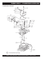
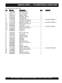
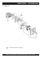
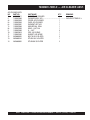
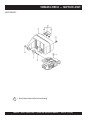
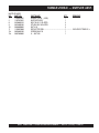
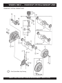
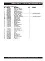
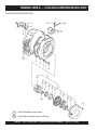
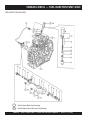
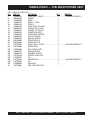
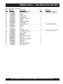
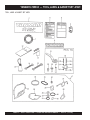
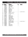
1
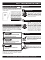
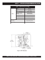
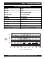
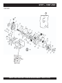
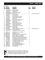
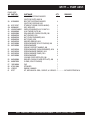
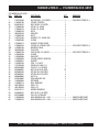
OPERATION AND PARTS MANUAL MODEL QP3TY TRASH PUMP (Yanmar L70EE-D Diesel Engine) Revision #2 (11/15/10) To find the latest revision of this publication, visit our website at: www.multiquip.com THIS MANUAL MUST ACCOMPANY THE EQUIPMENT AT ALL TIMES. Diesel engine exhaust and some of PAGE 2 — QP3TY TRASH PUMP — OPERATION AND PARTS MANUAL — REV. #2 (11/15/10) QP3TY TRASH PUMP — OPERATION AND PARTS MANUAL — REV. #2 (11/15/10) — PAGE 3 QP3TY — TABLE OF CONTENTS QP3TY Trash Pump Yanmar L70EE-D Engine Cylinder Block Assembly ................................... 34-35 Cylinder Head and Cover Assembly ................. 36-37 Air Cleaner Assembly........................................ 38-39 Muffler Assembly .............................................. 40-41 Crankshaft, Piston and Camshaft Assembly .... 42-43 Lub., Oil Pump and Governor Assembly........... 44-45 Cooling and Starting Assembly......................... 46-47 Fuel Injection Pump Assembly .......................... 48-49 Fuel Tank and Fuel Line Assembly ................... 50-51 Tool, Label and Gasket Set Assembly .............. 52-53 Here’s How To Get Help ............................................ 3 Table of Contents ...................................................... 4 Parts Ordering Procedures ....................................... 5 Safety Message Alert Symbols .............................. 6-7 Rules For Safe Operation ...................................... 8-9 Pump Specifications/Dimensions .............................10 Engine Specifications ...............................................11 General Information .................................................12 Pump Components ..................................................13 Refueling ..................................................................14 Basic Engine ............................................................15 Pre-Inspection (Engine) ...........................................16 Terms and Condition Of Sale — Parts .................... 54 Pre-Setup (Pump) ....................................................17 Initial Start-up (Engine) ...................................... 18-19 Maintenance (Pump) ......................................... 20-21 Maintenance (Engine)........................................ 22-23 Preparation for Long-Term Storage .........................24 Troubleshooting (Engine) .........................................26 Troubleshooting (Pump)...........................................27 Explanation Of Code In Remarks Column ...............28 Suggested Spare Parts ............................................29 Pump Assy. ........................................................ 30-33 NOTE Specification and part number are subject to change without notice. PAGE 4 — QP3TY TRASH PUMP — OPERATION AND PARTS MANUAL — REV. #2 (11/15/10) QP3TY — SAFETY MESSAGE ALERT SYMBOLS FOR YOUR SAFETY AND THE SAFETY OF OTHERS! Safety precautions should be followed at all times when operating this equipment. Failure to read and understand the Safety Messages and Operating Instructions could result in injury to yourself and others. This Owner's Manual has been developed to provide complete instructions for the safe and efficient operation of the Multiquip Model QP3TY Trash Pump. Refer to the NOTE engine manufacturers instructions for data relative to its safe operation. Before using this pump, ensure that the operating individual has read and understands all instructions in this manual. SAFETY MESSAGE ALERT SYMBOLS The three (3) Safety Messages shown below will inform you about potential hazards that could injure you or others. The Safety Messages specifically address the level of exposure to the operator, and are preceded by one of three words: DANGER, WARNING, or CAUTION. DANGER You WILL be KILLED or SERIOUSLY INJURED if you DO NOT follow these directions. WARNING You CAN be KILLED or SERIOUSLY INJURED if you DO NOT follow these directions. CAUTI CAUTION You CAN be INJURED if you DO NOT follow these directions. HAZARD SYMBOLS Lethal Exhaust Gases Engine exhaust gases contain poisonous carbon monoxide. This gas is colorless and odorless, and can cause death if inhaled. NEVER operate this equipment in a confined area or enclosed structure that does not provide ample free flow air. Explosive Fuel GASOLINE is extremely flammable, and its vapors can cause an explosion if ignited. DO NOT start the engine near spilled fuel or combustible fluids. DO NOT fill the fuel tank while the engine is running or hot. DO NOT overfill tank, since spilled fuel could ignite if it comes into contact with hot engine parts or sparks from the ignition system. Store fuel in approved containers, in well-ventilated areas and away from sparks and flames. NEVER Burn Hazards Engine components can generate extreme heat. To prevent burns, DO NOT touch these areas while the engine is running or immediately after operations. Never operate the engine with heat shields or heat guards removed. Rotating Parts NEVER operate equipment with covers, or guards removed. Keep fingers, hands, hair and clothing away from all moving parts to prevent injury. Potential hazards associated with the QP3TY Trash Pump operation will be referenced with Hazard Symbols which appear throughout this manual, and will be referenced in conjunction with Safety Message Alert Symbols. PAGE 6 — QP3TY TRASH PUMP — OPERATION AND PARTS MANUAL — REV. #2 (11/15/10) QP3TY — SAFETY MESSAGE ALERT SYMBOLS Accidental Starting Respiratory Hazard ALWAYS place the engine ON/OFF switch in the OFF position when the pump is not in use. ALWAYS wear approved respiratory protection. Equipment Damage Messages Sight and Hearing hazard ALWAYS wear approved eye and hearing protection. Other important messages are provided throughout this manual to help prevent damage to your pump, other property, or the surrounding environment. NOTE This pump, other property, or the surrounding environment could be damaged if you do not follow instructions. QP3TY TRASH PUMP — OPERATION AND PARTS MANUAL — REV. #2 (11/15/10) — PAGE 7 RULES FOR SAFE OPERATION DANGER Failure to follow instructions in this manual may lead to serious injury or even death! This equipment is to be operated by trained and qualified personnel only! This equipment is for industrial use only. The following safety guidelines should always be used when operating the trash pump: GENERAL SAFETY ■ DO NOT operate or service this equipment before reading this entire manual. ■ This equipment should not be operated by persons under 18 years of age. ■ NEVER operate this equipment without proper protective clothing, shatterproof glasses, steel-toed boots and other protective devices required by the job. ■ NEVER touch the hot exhaust manifold, muffler or cylinder. Allow these parts to cool before servicing engine or pump. ■ High Temperatures – Allow the engine to cool before adding fuel or performing service and maintenance functions. Contact with hot components can cause serious burns. ■ The engine of this pump requires an adequate free flow of cooling air. NEVER! operate the pump in any enclosed or narrow area where free flow of the air is restricted. If the air flow is restricted it will cause serious damage to the pump or engine and may cause injury to people and property. Remember the pump's engine gives off DEADLY gases. ■ NEVER operate this equipment when not feeling well due to fatigue, illness or taking medicine. ■ ALWAYS refuel in a well-ventilated area, away from sparks and open flames. ■ NEVER operate this equipment under the influence or drugs or alcohol. ■ ALWAYS use extreme caution when working with flammable liquids. When refueling, stop the engine and allow it to cool. DO NOT smoke around or near the machine. Fire or explosion could result from fuel vapors, or if fuel is spilled on a hot engine. ■ Whenever necessary, replace nameplate, operation and safety decals when they become difficult read. ■ ALWAYS check the machine for loosened threads or bolts before starting. ■ ALWAYS wear proper respiratory (mask) hearing and eye protection equipment when operating the pump. ■ NEVER operate the pump in an explosive atmosphere or near combustible materials. An explosion or fire could result causing severe bodily harm or even death. ■ Topping-off to filler port is dangerous, as it tends to spill fuel. ■ Refer to the Engine Owner's Manual for engine technical questions or information. ■ NEVER use accessories or attachments, which are not recommended by Multiquip for this equipment. Damage to the equipment and/or injury to user may result. ■ Manufacturer does not assume responsibility for any accident due to equipment modifications. PAGE 8 — QP3TY TRASH PUMP — OPERATION AND PARTS MANUAL — REV. #2 (11/15/10) RULES FOR SAFE OPERATION ■ NEVER Run engine without air cleaner. Severe engine damage may occur. ■ ALWAYS read, understand, and follow procedures in Operator’s Manual before attempting to operate equipment. ■ ALWAYS be sure the operator is familiar with proper safety precautions and operation techniques before using pump. ■ ALWAYS store equipment properly when it is not being used. Equipment should be stored in a clean, dry location out of the reach of children. ■ NEVER leave the pump unattended, turn off engine when unattended. ■ Unauthorized equipment modifications will void all warranties. ■ NEVER pump volatile, explosive, flammable or low flash point fluids. These fluids could ignite or explode. ■ NEVER operate the pump in an explosive atmosphere. ■ Before starting the pump, check that the clean-out cover is securely fasten. ■ ALWAYS ensure pump is on level ground before use. ■ Become familiar with the components of the pump before operating. ■ NEVER pump corrosive chemicals or water containing toxic substances. These fluids could create serious health and environmental hazards. Contact local authorities for assistance. ■ NEVER open the priming plug when pump is hot. Hot water inside could be pressurized much like the radiator of an automobile. Allow pump to cool to the touch before loosening plug. ■ NEVER open the pump housing during operation or start the pump with the clean-out cover removed. The rotating impeller inside the pump can cut or sever objects caught in it. ■ NEVER block or restrict flow from discharge hose. Remove kinks from discharge line before starting pump. Operation with a blocked discharge line can cause water inside pump to overheat. ■ ALWAYS fill the pump casing with water before starting the engine. Failure to maintain water inside the pump housing will cause severe damage to the pump. ■ In winter drain water from pump housing to prevent freezing. ■ High Temperatures – Always stop engine and allow the engine to cool before adding fuel, oil or performing service and maintenance functions. Contact with hot components can cause serious burns. ■ NEVER disconnect any "emergency or safety devices". These devices are intended for operator safety. Disconnection of these devices can cause severe injury, bodily harm or even death! Disconnection of any of these devices will void all warranties. Maintenance Safety ■ NEVER lubricate components or attempt service on a running machine. ■ ALWAYS allow the machine a proper amount of time to cool before servicing. ■ Keep the machinery in proper running condition. ■ Fix damage to the machine immediately and always replace broken parts, or missing decals. ■ Dispose of hazardous waste properly. Examples of potentially hazardous waste are used motor oil, fuel and fuel filters. ■ DO NOT use food or plastic containers to dispose of hazardous waste. ■ DO NOT pour waste, oil or fuel directly onto the ground, down a drain or into any water source. Emergencies ■ ALWAYS know the location of the nearest fire extinguisher. ■ ALWAYS know the location of the nearest first aid kit. ■ In emergencies always know the location of the nearest phone or keep a phone on the job site. Also know the phone numbers of the nearest ambulance, doctor and fire department. This information will be invaluable in case of an emergency. QP3TY TRASH PUMP — OPERATION AND PARTS MANUAL — REV. #2 (11/15/10) — PAGE 9 QP3TY — SPECIFICATIONS/DIMENSIONS (PUMP) Table 1. Specifications (Pump) Model QP- 3TY Type Trash Pump Suction & Discharge Size Pump 3.00 in. (76 mm.) Maximum Pumping Capacity 383 gallons/minute (1,450 liters/minute) Max. Solids Diameter Dimension (L x W x H) 1.50 in. (38 mm.) Max. Lift 25 ft. (7.62 meters) Max. Head 90 ft. (27.0 meters) 27.8 x 20.0 X 25.0 in. (705 X 510 X 635 mm.) 159 lbs. (72 Kg.) Dry Net Weight Figure 1. QP3TY Dimensions PAGE 10 — QP3TY TRASH PUMP — OPERATION AND PARTS MANUAL — REV. #2 (11/15/10) QP3TY — SPECIFICATIONS (ENGINE) Table 2. Engine Specifications (YANMAR) Engine Make YANMAR Engine Model L-70EE-D Engine Type Air-cooled 4-cycle Diesel Engine Cylinder Bore X Stroke 3.07 x 2.44 in (78 x 62 mm) Displacement 10.01 fl oz (296 cc) Maximum Ouput 6.7 HP @3,600 RPM Fuel Tank Capacity 3.5 quarts (3.31 liters) Oil Capacity 1.16 quarts (1.10 liters) Starting Method Recoil Dry Net Weight 72.75 lbs. (33 kg) Dimensions (L x W x H) 15.11 x 16.57 x 17.71 in (384 x 421 x 450 mm) 100 90 80 70 TOTAL HEAD FT. 60 50 40 1.6 FT. 30 20 23.3 FT. 10 FT. 16.7 FT. 3.3 FT. 10 0 0 50 100 150 200 250 300 350 US GALLONS PER MINUTE QP3TY TRASH PUMP — OPERATION AND PARTS MANUAL — REV. #2 (11/15/10) — PAGE 11 400 QP3TY — GENERAL INFORMATION APPLICATION The QP3TY Trash Pump is designed to be used for dewatering applications. Both the suction and discharge ports on the QP3TY trash pump use a 3-inch diameter opening, which allows the pump to pump at a rate of approximately 383 gallons/minute (gpm) or 1,450 liters/minute (lpm). Trash or self-priming pumps are designed to purge air from the suction line and create a partial vacuum in the pump body. The reduced atmospheric pressure inside the pump allows water to flow through the suction line and into the pump body. The centrifugal force created by the rotating impeller pressurizes the water and expels it from the pump. Elevation Higher elevations will effect the performance of the pump. Due to less atmospheric pressure at higher altitudes, pumps DO NOT have the priming ability that they have at sea level. This is due to the “thinner air” or lack of oxygen at higher altitudes. A general rule of thumb is that for every 1,000 feet of elevation above sea level a pump will lose one foot of priming ability. For example, in Flagstaff, Arizona where the elevation is approximately 7,000 feet, the pump would have a suction lift of 25 feet rather than the 18 feet at sea level. Table 3 shows suction lift at various elevations. Engine Table 3. Suction Lift at Various Elevations This trash pump is powered by an 6.7 horsepower, air-cooled, 4-stroke, YANMAR L70EE-D diesel engine. Trash Pump Trash pumps derive their name from their ability to handle a greater amount of debris and solids than standard centrifugal pumps. This pump generally handle solids up to 1/2 the size of the discharge opening making them less likely to clog. Also trash pumps are capable of handling water with 25% solids by weight. The advantage of using a trash pump is that it can be quickly and easily disassembled in the field "without tools" and easily cleaned when clogged. Suction Lift This pump is intended to be used for dewatering applications and is capable of suction lifts up to 25 feet at sea level. For optimal suction lift performance, keep the suction hose or line as short as possible. In general, always place the pump as close to the water as possible. Pump Support The pump should always be placed on solid stationary ground in a level position. NEVER place the pump on soft soil. The suction hose or pipe connection should always be checked for tightness and leaks. A small suction leak in the hose or fittings could prevent the pump from priming. Altitude Feet (Meters) Suction Lift in Feet (Meters) Sea Level 10.0 (3.048) 15.0 (4.572) 20.0 (6.096) 25.0 (7.620) 2,000 (610) 8.80 (2.680) 13.2 (4.023) 17.6 (5.364) 22.0 (6.705) 4,000 (1,219) 7.80 (2.377) 11.7 (3.566) 15.6 (4.754) 19.5 (5.943) 6,000 (1,829) 6.90 (2.103) 10.4 (3.169) 13.8 (4.206) 17.3 (5.273) 8,000 (2,438) 6.20 (1.889) 9.30 (2.834) 12.4 (3.779) 15.5 (4.724) 10,000 (3,048) 5.70 (1.737) 8.60 (2.621) 11.4 (3.474) 14.3 (4.358) Table 4 shows percentage drops in performance as elevation increases. Table 4. Performance Loss at Various Elevations Altitude Feet (Meters Discharge Flow Discharge Head Sea Level 100% 100% 2,000 (610) 97% 95% 4,000 (1,219) 95% 91% 6,000 (1,829) 9 3% 87% 8,000 (2,438) 91% 83% 10,000 (3,048) 88% 78% PAGE 12 — QP3TY TRASH PUMP — OPERATION AND PARTS MANUAL — REV. #2 (11/15/10) QP3TY — PUMP COMPONENTS Figure 2 shows a typical application using the QP3TY Trash pump. Please note that this pump is intended for the removal of clean water and water containing some debris and solids. Maximum size of solids should not exceed 1.5 inch (30 mm) in diameter. DO NOT set strainer on bottom of water bed. Placing the strainer above the water bed will prevent the pump from drawing in excessive amounts of sand and foreign debris. Figure 2. QP- 3TY Pump Application 1. 2. Pump – The model QP3TY is a 3-inch trash pump used in general dewatering applications. Typical dewatering applications consist of manholes, septic tanks, fast and slow seepage ditch water, silt water, mud water and muck water. Fill Cap – Prior to operation, the pump casing should be filled with water. Remove this cap to add water to the pump. After the initial prime, a sufficient amount of water will be retained in the casing so that the operator will not need to re-prime later. If the casing is dry or has insufficient water, the pump will have difficulty in priming which could lead to premature mechanical seal wear thus causing damage to the pump. 3. Discharge Port – Connect a 3-inch discharge hose to either port (one of two ports). 4. Worm Clamp – Used to secure the hose to the inlet and outlet ports on the pump. Use two clamps to secure the hose on the inlet side of the pump. 5. Discharge Hose – Connect this flexible rubber hose to the discharge port on the pump. Make sure that the hose lays flat and is not kinked. Use only recommended type discharge hose. Contact Multiquip Parts Department for ordering information. 6. Suction Port – Connect a 3-inch inlet hose to this port. Use two worm clamps to secure the hose. 7. Suction Hose – Connect this flexible rubber hose to the suction portion the pump. Make sure that the hose lays flat and is not kinked. Use only recommended type suction hose. Contact Multiquip Parts Department for ordering information. 8. Clean-out Cover Handles – To gain access to the pump's clean-out area, grip both handles, then pull to remove cover. Make sure both locking knobs have been released before attempting to remove clean-out cover. 9. Drain Plug – Remove this plug to drain water from the pump. 10. Clean-out Cover – Remove cover to gain access to the clean-out area. 11. Locking Knobs – Turn both knobs clockwise to secure clean-out cover, turn counterclockwise to release cover. 12. Strainer – Always attach a strainer to the bottom side of the suction hose to prevent large objects and debris from entering the pump. Strainer should be positioned so that it will remain completely under water. Running the pump with the strainer above water for long periods can damage pump. QP3TY TRASH PUMP — OPERATION AND PARTS MANUAL — REV. #2 (11/15/10) — PAGE 13 QP3TY — REFUELING DANGER Adding fuel to the tank should be done only when the engine is stopped and has had an opportunity to cool down. In the event of a fuel spill, DO NOT attempt to start the engine until the fuel residue has been completely wiped up, and the area surrounding the engine is dry. If pump is placed in a truck bed with a plastic liner, REMOVE pump from truck bed and place on ground (Figure 3) to refuel. The possibility of fire or explosion exists, due to static electricity. PLASTIC TRUCK-BED LINER DANGER DO NOT ADD FUEL TO TRASH PUMP IF TRASH PUMP IS PLACED INSIDE TRUCK-BED WITH PLASTIC LINER. POSSIBILITY EXISTS OF EXPLOSION OR FIRE DUE TO STATIC ELECTRICITY. Figure 3. Pump Refueling PAGE 14 — QP3TY TRASH PUMP — OPERATION AND PARTS MANUAL — REV. #2 (11/15/10) QP3TY — BASIC ENGINE Figure 4. Engine Controls and Components ENGINE COMPONENTS Figure 4 illustrates the location of the major components of the engine. Each component is described below: 1. Fuel Filler Cap – Remove this cap to add diesel fuel to the fuel tank. Make sure cap is tightened securely. DO NOT overfill. 7. Oil Filler Cap / Dipstick – Remove this cap to add oil to the engine crankcase. Read dipstick to determine if oil level is low. DO NOT overfill. 2. Fuel Tank – Capacity is 3.5 quarts (3.3 liters) of diesel fuel. 8. Oil Drain Plug – Unscrew plug to drain oil from engine crankcase. Dispose of oil in a safe manner. 3. Air Cleaner – Prevents dirt and other debris from entering the fuel system. Remove wing-nut on top of air filter cannister to gain access to filter element. 9. Decompression Lever – Press down before starting engine. To prevent damage to engine, DO NOT use for any other purpose. 4. Muffler – Used to reduce noise and emissions. 5. Recoil Starting Handle (pull rope) – Used to start engine. 6. Recoil Starter – Manual-starting method. Pull the starter grip until resistance is felt, then pull briskly and smoothly. 10. Fuel Cock – Controls the flow of diesel fuel to the carburetor. Must be in the ON position when starting and running the engine. QP3TY TRASH PUMP — OPERATION AND PARTS MANUAL — REV. #2 (11/15/10) — PAGE 15 QP3TY — PRE-INSPECTION (ENGINE) CAUTION NEVER operate the pump in a confined area or enclosed area structure that does not provide ample free flow of air. 3. Insert and remove the dipstick without screwing it into the filler neck. Check the oil level shown on the dipstick. 4. If the oil level is low (Figure 6), fill to the edge of the oil filler hole with the recommended oil type (Table 5). Maximum oil capacity is 1.16 quarts (1.1 liters) ALWAYS wear approved eye and hearing protection before operating the pump. Before Starting 1. Read safety instructions at the beginning of manual. 2. Clean the pump, removing dirt and dust, particularly the engine cooling air inlet, carburetor and air cleaner. 3. Check the air filter for dirt and dust. If air filter is dirty, replace air filter with a new one as required. 4. Check carburetor for external dirt and dust. Clean with dry compressed air. 5. Check fastening nuts and bolts for tightness. Figure 6. Engine Oil Dipstick (Oil Level) Table 5. Oil Type Season Temperature Oil Type Summer 25°C or Higher SAE 10W-30 Spring/Fall 25°C~10°C SAE 10W-30/20 Winter 0°C or Lower SAE 10W-10 Explosive Fuel Engine Oil Check 1. To check the engine oil level, place the pump on secure level ground with the engine stopped. 2. Remove the filler dipstick from the engine oil filler hole (Figure 5) and wipe clean. DANGER Motor fuels are highly flammable and can be dangerous if mishandled. DO NOT smoke while refueling. DO NOT attempt to refuel the pump if the engine is hot! or running. Fuel Check 1. Remove the gasoline cap located on top of fuel tank. 2. Visually inspect to see if the fuel level is low. If fuel is low, replenish with unleaded fuel. 3. When refueling, be sure to use a strainer for filtration. DO NOT top-off fuel. Wipe up any spilled fuel immediately! Figure 5. Engine Oil Dipstick (Removal) PAGE 16 — QP3TY TRASH PUMP — OPERATION AND PARTS MANUAL — REV. #2 (11/15/10) QP3TY — PRE-SETUP (PUMP) Before Starting 1. Read safety instructions at the beginning of manual. NOTE 2. Place pump as near to water as possible, on a firm flat, level surface. 3. To prime pump, remove fill cap (Figure 2) and fill pump casing with water. If the pump casing is not filled with water before starting, it will not begin pumping. CAUTION Pump casing must be filled with water before using pump. Otherwise pump will not be able to begin pumping. Suction and discharge hoses are available from Multiquip. Contact your nearest dealer for more information. 5. The discharge hose is usually a collapsible (thin-walled) hose, however if a thin-walled discharge hose is not available, a rigid suction hose can be substituted in its place. 6. Make sure the suction strainer (Figure 2) is clean and securely attached to the water end of the suction hose. The strainer is designed to protect the pump by preventing large objects from being pulled into the pump. CAUTION WARNING DO NOT open fill cap if pump is hot! Water inside may be under pressure. 4. Check for leaks between pump and engine. If water is leaking between the pump and engine housing, the seal inside the pump may be worn or damaged. Continued operation of the pump is not recommended. Further usage of the pump under these conditions may cause severe water damage to engine. The strainer should be positioned so it will remain completely under water. Running the pump with the strainer above water for long periods can damage the pump. CAUTION DO NOT pump flammable fluids, corrosive chemicals or fluids containing toxic substances. These fluids can create potentially dangerous health and environmental hazards. Contact local authorities for assistance. Hoses and Clamps 1. Check that all hoses are securely attached to the pump. Make certain suction hose (Figure 2) does not have any air leakage. Tighten hose clamps and couplings as required. 2. It is recommended that 2 clamps be used when securing the suction hose to the inlet side (suction) of the pump. 3. Remember suction hoses must be rigid enough not to collapse when the pump is in operation. 4. Check that the discharge hose (Figure 2) is not restricted. Place hose so that it lays as straight as it is possible on the ground. Remove any twists or sharp bends from hose which may block the flow of water. CAUTION This pump uses a water-cooled mechanical seal to prevent water from seeping into the engine. The passage of water through the pump casing lubricates the seal and prevents it from overheating. NEVER! operate the pump without water in the casing as this will cause damage to the mechanical seal. QP3TY TRASH PUMP — OPERATION AND PARTS MANUAL — REV. #2 (11/15/10) — PAGE 17 QP3TY — INITIAL START-UP (ENGINE) 4. CAUTION DO NOT attempt to operate the pump until the Safety, General Information and Inspection sections of this manual have been read and thoroughly understood. Grasp the starter grip (Figure 9) and slowly pull it out until you feel the strongest resistance then return the starter grip to the initial position. This section is intended to assist the operator with the initial start-up of the trash pump. It is extremely important that this section be read carefully before attempting to use the pump in the field. Starting the Engine (YANMAR engine) 2. Open the fuel cock (Figure 7). Figure 9. Starter Grip CAUTION Do not allow the starter grip to snap back against the engine. Return it gently to prevent damage to the starter. Figure 7. Open Fuel Cock 3. Move the engine speed lever to the START position (Figure 8). 5. Push down decompression lever (Figure 10) and release. START ENGINE SPEED LEVER Figure 10. Decompression Lever Figure 8. Engine Speed Lever (START position) 6. Pull the starter grip again, hard and fast, pulling it all the way out to start engine. 7. If the engine does not start, repeat steps 4 to 6. CAUTI CAUTION ALWAYS run engine at full speed while pumping. PAGE 18 — QP3TY TRASH PUMP — OPERATION AND PARTS MANUAL — REV. #2 (11/15/10) QP3TY — INITIAL START-UP (ENGINE) Stopping The Engine Normal Shutdown 1. Move the engine speed lever to the low speed and run the engine for about three minutes with no load. 2. After the engine cools, move the engine speed lever to the STOP position (Figure 11). STOP ENGINE SPEED LEVER Figure 11. Engine Speed Lever (STOP Position) 3. Close the fuel cock (Figure 12). Figure 12. Close Fuel Cock 4. Slowly pull the starter grip (Figure 9) until strong resistance is felt and leave it in this position. This prevents rust from forming while the engine is not in use. CAUTI CAUTION When stopping the engine, reduce the load slowly. Do not stop engine suddenly since it may cause the temperature to rise abnormally. Emergency Shutdown 1. To stop engine immediately, quickly place the engine speed lever to the STOP position. QP3TY TRASH PUMP — OPERATION AND PARTS MANUAL — REV. #2 (11/15/10) — PAGE 19 QP3TY — MAINTENANCE (PUMP) Pump Vacuum Test CAUTI CAUTION DO NOT attempt to start the engine unless the pump has previously been primed with water. Severe pump damage will occur if pump has not been primed. To perform the pump vacuum test do the following: 1. Remove the pump fill cap (Figure 2), and fill the pump with water. 2. Start the engine as outlined in the initial start-up section, and wait for the pump to begin pumping. 3. As shown in Figure 13, place a water hose inside the discharge opening of the pump, and turn on the water. This flow of water into the discharge opening will prevent the pump from running dry. 4. Place the Pump Vacuum Tester (P/N 7000030) over the pump suction (inlet) opening (Figure 13) with the vacuum gauge facing upwards. It may be necessary to apply a small amount of water around the rubber seal of the vacuum tester to make a good suction fit. 5. Check and make sure that there are no air leaks between the vacuum tester and the inlet port on the pump. If air leaks are present reset vacuum tester. 6. Run the pump for a few minutes while monitoring the vacuum gauge. If the gauge indicates a reading between -25 and -20 in. Hg. (inches of mercury), then it can be assumed that the pump is working correctly. NOTE 25 in. Hg. (inches of mercury) translates into 25 feet of lift at sea level. 7. If the vacuum tester gauge indicates a reading below -20 in. Hg, it can then be assumed that the pump is not functioning correctly, and corrective action needs to be taken. 6. To test the flapper valve, shut down the engine. The vacuum tester should remain attached to the pump suction inlet port by vacuum. This indicates the pump's flapper valve is seating properly to hold water in the suction hose when the engine is stopped. This prevents backflow and allows for faster priming when the engine is restarted. Adjusting Impeller Clearance 1. If it is necessary to replace impeller or volute, be sure clearance between impeller and volute is adjusted correctly. 2. The impeller should be as close to the volute as possible without rubbing against it. Clearance is adjusted by adding or removing shims from behind the impeller. 3. Check clearance between impeller and insert by slowly pulling starter rope to turn impeller. Remove spark plug to make it easier to turn impeller. It is important not to remove too many shims or the clearance between the impeller and volute will NOTE become too wide and pump performance will be reduced. Remember as the impeller wear down, additional shims may be required to maintain the clearance between the impeller and insert. 4. Check the impeller every six months for wear, and for clearance between the impeller face and the volute. Also check the shaft seal for wear, as well as the shaft sleeve. Pump Cleaning After pumping water containing large amounts of dirt and debris, perform the following: 1. Remove the drain plug from the pump housing (Figure 2) and drain any water left in the pump. 2. Loosen the two locking hand knobs (turn counterclockwise) and remove clean-out cover. 3. Clean and remove dirt, debris from pump casing. Inspect impeller and volute for wear. Replace any damaged or worn parts. CAUTI CAUTION The impeller may develop sharp edges. Use extreme care when cleaning around the impeller to prevent being cut. PAGE 20 — QP3TY TRASH PUMP — OPERATION AND PARTS MANUAL — REV. #2 (11/15/10) QP3TY — MAINTENANCE (PUMP) NOTE Pressure reading may vary depending on altitude. See Tables 3 and 4 on page 12. Figure 13. Pump Vacuum Tester QP3TY TRASH PUMP — OPERATION AND PARTS MANUAL — REV. #2 (11/15/10) — PAGE 21 QP3TY — MAINTENANCE (ENGINE) Engine Maintenance Perform engine maintenance procedures as referenced by Table 6 below: Table 6. Engine Maintenance Schedule DESCRIPTION (3) OPERATION BEFORE CHECK X FIRST EVERY MONTH 3 MONTHS OR OR 10 HRS. 25 HRS. EVERY 6 MONTHS OR 50 HRS. EVERY YEAR OR 100 HRS. EVERY 2 YEARS OR 200 HRS. Engine Oil CHANGE CHECK X X Air Cleaner CHANGE X (1) All Nuts & Bolts Re-tighten If Necessary Cooling Fins CHECK Spark Arrester CLEAN X Fuel Tank CLEAN X Fuel Filter CHECK X Idle Speed CHECK-ADJUST X (2) Valve Clearance CHECK-ADJUST Fuel lines CHECK X X X (2) Every 2 years (replace if necessary) (2) (1) Service more frequently when used in DUSTY areas. (2) These items should be serviced by your service dealer, unless you have the proper tools and are mechanically proficient. Refer to the YANMAR shop manual for service procedures. (3) For commercial use, log hours of operation to determine proper maintenance intervals. NOTE Reference manufacturer engine manual for specific servicing instructions. PAGE 22 — QP3TY TRASH PUMP — OPERATION AND PARTS MANUAL — REV. #2 (11/15/10) QP3TY — MAINTENANCE (ENGINE) Maintenance Perform the engine maintenance procedures as indicated below: DAILY ■ Thoroughly remove dirt and oil from the engine and control area. Clean or replace the air cleaner elements as necessary. Check and retighten all fasteners as necessary. Check the spring box and bellows for oil leaks. Repair or replace as needed. WEEKLY ■ Remove the fuel filter cap and clean the inside of the fuel tank. ■ Remove or clean the filter at the bottom of the tank. ENGINE OIL 1. Drain the engine oil when the oil is warm as shown in Figure 14. DANGER DO NOT use gasoline as a cleaning solvent, because that would create a risk of fire or explosion. ENGINE AIR CLEANER 1. Loosen the wing nut and detach the cover of the air cleaner shown in Figure 15. 2. Tap the element (Figure 15) several times on a hard surface to remove dirt, or blow compressed air [not exceeding 30 psi (207 kPa, 2.1 kgf/cm2)] through the element. side. NEVER wash the element with detergent because the element is oilsoaked type. Replace the element when the output decreases or bad exhaust color is noticed. 2. Remove the oil drain bolt and sealing washer and allow the oil to drain into a suitable container. 3. Replace engine oil with recommended type oil as listed in Table 5. Engine oil capacity is 0.85 quarts (0.8 liters). DO NOT overfill. 4. Install drain bolt with sealing washer and tighten securely. Figure 15. Engine Air Cleaner Figure 14. Engine Oil (Draining) QP3TY TRASH PUMP — OPERATION AND PARTS MANUAL — REV. #2 (11/15/10) — PAGE 23 QP3TY — PREPARATION FOR LONG -TERM STORAGE Pump Storage For storage of the pump for over 30 days, the following is required: Pull the decompression lever up. Pull the recoil starter grip slowly. STOP when it feels tight. This closes the intake and exhaust valves (compression position) , and helps prevents rust from forming. Wipe any oil or dirt that may have accumulated on the engine. Remove the drain plug from the pump and drain out any water left in the housing. Drain the fuel tank completely. Run the engine for about 3 minutes and then stop. Stop the engine. Drain the engine crankcase oil while the Remove the pump cover and clean the inside of pump engine is still warm. Fill engine crankcase with fresh oil. housing. Coat the inside of pump housing with a light Remove the rubber plug (Figure 16) on the rocker arm cover film of oil to reduce corrosion. A spray can of oil works and add about 2 cc of lube oil. Reinstall rubber plug. well for this application. Cover suction and discharge ports with duct tape to prevent any foreign matter from falling into pump. Cover pump and engine with plastic covering or equivalent and store in a clean, dry place. Figure 16. Decompression Lever Push the decompression lever down (non-decompression position, Figure 16) and hold it while you pull the recoil starter grip (Figure 17) 2 or 3 times. DO NOT start the engine. To protect the water cooled-seals, place one-half pint of lubricating oil (new or used) through the discharge opening on the pump and crank the engine several times. This will prevent excessive corrosion and also keep the mechanical seal lubricated. Figure 17. Recoil Starter Grip PAGE 24 — QP3TY TRASH PUMP — OPERATION AND PARTS MANUAL — REV. #2 (11/15/10) NOTE PAGE QP3TY TRASH PUMP — OPERATION AND PARTS MANUAL — REV. #2 (11/15/10) — PAGE 25 QP3TY — TROUBLESHOOTING (ENGINE) TABLE 7. ENGINE TROUBLESHOOTING SYMPTOM POSSIBLE PROBLEM SOLUTION Speed control lever is in "STOP" position? Set speed control lever to "START" position. No fuel reaching injection pump? Add fuel. Check entire fuel system. Defective fuel pump? Replace fuel pump. Fuel filter clogged? Replace fuel filter and clean tank. Faulty fuel supply line? Replace or repair fuel line. Compression too low? Check piston, cylinder and valves. Adjust or repair per engine repair manual. Fuel injector not working correctly? Repair or replace injector in accordance with engine repair manual. Oil pressure too low? Check engine oil pressure. Low star ting temperature limit exceeded Comply with cold star ting instructions and proper oil viscosity. Fuel separates has inadequate resistance to low temperatures? Check whether clear (not turbid) fuel emerges from the fuel line (detach from injection pump). If the fuel is turbid or separated, warm up the engine or drain the complete fuel supply system. Refuel with winter grade diesel fuel. Engine oil too thick? Refill engine crankcase with correct type of oil for winter environment. Engine fires but stops soon as star ter is switched off. Fuel filter blocked? Replace fuel filter. Fuel supply blocked? Check the entire fuel system. Engine stops by itself during normal operation. Fuel tank empty? Add fuel. Fuel filter blocked? Replace fuel filter. Fuel tank empty? Fill with No.2 diesel fuel. Fuel filter clogged? Replace fuel filter. Fuel tank venting is inadequate? Ensure that tank is adequately vented. Speed control lever does not remain in selected position? See engine manual for corrective action. Engine oil level too full? Correct engine oil level? Air filter blocked? Clean or replace air filter. Incorrect valve clearances? Adjust valves per engine specification. Malfunction at injector? See engine manual. Engine will not star t or star t is delayed, although engine can be turned over. At low temperatures engine will n o t st a r t . Low engine power, output and speed. Low engine power output and low speed, black exhaust smoke. PAGE 26 — QP3TY TRASH PUMP — OPERATION AND PARTS MANUAL — REV. #2 (11/15/10) QP3TY — TROUBLESHOOTING (PUMP) TABLE 8. PUMP TROUBLESHOOTING SYMPTOM Pump does not take on water. POSSIBLE PROBLEM Not enough priming water in the housing? Add water. Engine speed too low? Increase throttle. Strainer plugged? Clean strainer. Suction hose damaged? Replace or repair hose, and clamps Air leak at suction por t? Check that fittings are tight and properly sealed. Pump is located too high above water line? Move pump closer to water. Debris collecting in pump housing? Clean pump housing. Too much distance between impeller and volute. Adjust clearance by adding shims or replace impeller. Min. .006" - Max. .020" Water leaking out weep hole between pump and engine? Check condition of mechanical seal and gaskets, between pump end and engine housing. Engine speed too low? Increase throttle speed. Pump takes in water, little or no Suction strainer par tially plugged? discharge. Impeller/Volute worn? Impeller does not turn: pump is hard to star t. Clean strainer. Adjust clearance by adding shims or replace impeller/volute Fittings/clamps are not sealed properly? Tighten, replace or add clamp. (Keep extra seals on pump) Hose diameter is too large? Use smaller diameter hose or replace hose. Pressure too high? Check pressure, add additional clamp. Hose kinked or end blocked? Check hose. Impeller jammed or blocked? Open pump cover and clean dir t and debris from inside housing. Suction hose leaks at inlet. Discharge does not stay on coupling. SOLUTION Impeller and volute binding? Adjust clearance by removing shim from behind impeller. Defective engine? See Engine Owner's Manual. QP3TY TRASH PUMP — OPERATION AND PARTS MANUAL — REV. #2 (11/15/10) — PAGE 27 QP3TY — EXPLANATION OF CODE IN REMARKS COLUMN The following section explains the different symbols and remarks used in the Parts section of this manual. Use the help numbers found on the back page of the manual if there are any questions. NOTICE The contents and part numbers listed in the parts section are subject to change without notice. Multiquip does not guarantee the availability of the parts listed. SAMPLE PARTS LIST NO. 1 2% 2% 3 4 PART NO. PART NAME QTY. REMARKS 12345 BOLT......................1 .....INCLUDES ITEMS W/% WASHER, 1/4 IN............NOT SOLD SEPARATELY 12347 WASHER, 3/8 IN....1 .....MQ-45T ONLY 12348 HOSE ..................A/R ...MAKE LOCALLY 12349 BEARING ..............1 .....S/N 2345B AND ABOVE NO. Column QTY. Column Numbers Used — Item quantity can be indicated by a number, a blank entry, or A/R. A/R (As Required) is generally used for hoses or other parts that are sold in bulk and cut to length. A blank entry generally indicates that the item is not sold separately. Other entries will be clarified in the “Remarks” Column. REMARKS Column Some of the most common notes found in the “Remarks” Column are listed below. Other additional notes needed to describe the item can also be shown. Assembly/Kit — All items on the parts list with the same unique symbol will be included when this item is purchased. Unique Symbols — All items with same unique symbol Indicated by: “INCLUDES ITEMS W/(unique symbol)” (@, #, +, %, or >) in the number column belong to the same assembly or kit, which is indicated by a note in the “Remarks” column. Serial Number Break — Used to list an effective serial number range where a particular part is used. Duplicate Item Numbers — Duplicate numbers indicate multiple part numbers, which are in effect for the same general item, such as different size saw blade guards in use or a part that has been updated on newer versions of the same machine. NOTICE When ordering a part that has more than one item number listed, check the remarks column for help in determining the proper part to order. PART NO. Column Numbers Used — Part numbers can be indicated by a number, a blank entry, or TBD. TBD (To Be Determined) is generally used to show a part that has not been assigned a formal part number at the time of publication. A blank entry generally indicates that the item is not sold separately or is not sold by Multiquip. Other entries will be clarified in the “Remarks” Column. Indicated by: “S/N XXXXX AND BELOW” “S/N XXXX AND ABOVE” “S/N XXXX TO S/N XXX” Specific Model Number Use — Indicates that the part is used only with the specific model number or model number variant listed. It can also be used to show a part is NOT used on a specific model or model number variant. Indicated by: “XXXXX ONLY” “NOT USED ON XXXX” “Make/Obtain Locally” — Indicates that the part can be purchased at any hardware shop or made out of available items. Examples include battery cables, shims, and certain washers and nuts. “Not Sold Separately” — Indicates that an item cannot be purchased as a separate item and is either part of an assembly/kit that can be purchased, or is not available for sale through Multiquip. PAGE 28 — QP3TY TRASH PUMP — OPERATION AND PARTS MANUAL — REV. #2 (11/15/10) QP3TY — SUGGESTED SPARE PARTS QP3TY TRASH PUMP 1 TO 3 UNITS W/ YANMAR L48EE-D Qty. P/N Description 2 ............ KIT3T .................... KIT, MECHANICAL SEAL, O-RINGS 1 ............ 1992040032 .......... IMPELLER 2 ............ 0631211159 .......... FLOODING CAP, W/ O-RING 3 ............ 11425012581 ........ ELEMENT, AIR CLEANER 1 ............ 16081076630 ........ ROPE STARTER 1 ............ 11428855040 ........ CAP, FUEL TANK 3 ............ 11425055121 ........ FUEL FILTER, GAS TANK 1 ............ 11425035110 ........ STRAINER, OIL LUB 1 ............ 71487153100 ........ FUEL INJECTION VALVE ASSY 1 ............ 11425055100 ........ FUEL STRAINER, GAS TANK NOTE Part number on this Suggested Spare Parts List may supersede/ replace the P/N shown in the text pages of this book. QP3TY TRASH PUMP — OPERATION AND PARTS MANUAL — REV. #2 (11/15/10) — PAGE 29 QP3TY — PUMP ASSY. PUMP ASSY. 61 SEAL KIT 6 21 59 PAGE 30 — QP3TY TRASH PUMP — OPERATION AND PARTS MANUAL — REV. #2 (11/15/10) QP3TY — PUMP ASSY. PUMP ASSY. NO. PART NO. 1 1992100011 2 1992100020 3 13910001600014 4 1992100173 5 19920002200014 6 2367040033ASSY 7 1992000110 8 1992100742 9 1247100250 10 1992330410 11 1992250700 12 0105090820 13 07904330300014 14 1378350350 15 0105091045 16 43130006000014 17@ 0483602250 18 0489403400 19 2367214010P002 20 0481310800 21# 0482200240 22 23672140200014 23 0631211159 24 0631211159 25@ 0803442930 26@ 0811885446 27@ 0852834525 27-1@ 0852854525 28 0105090825 29 0131190823 30 0141090825 31 0131191290 32 0131191235 33 0105091055 34 0459220120 35 0723302040 36# 0458220100 37# 0191190750 PART NAME QTY. REMARKS CASING 1 CASING COVER 1 SUCTION COVER 1 DRAIN COVER 1 DRAIN COVER HANDLE 4 IMPELLER KIT ......................................................... 1 .......... INCLUDES ITEMS W/# VOLUTE CASING 1 SUCTION PLATE 1 DRAIN COVER SET HANDLE 2 SUCTION PLATE PACKING 1 WEAR PLATE 1 BOLT(CASING COVER), M8 x 20 4 NIPPLE, NPS3" X NPT3" 2 CHECK VALVE 1 BOLT(ENGINE), M10 X 45 4 CASING COVER SET PLATE 1 O-RING (DRAIN COVER) 1 O-RING (CASING), 4 X 340 MM 1 BASE, SS400 1 O-RING (NIPPLE) 2 O-RING, IMPELLER, MECH SEAL .......................... 2 .......... SEE NOTE BELOW ENGINE BASE,SS400 1 FLOODING CAP, PF1 1/2" W/ O-RING 1 DRAIN CAP, PF1 1/2" W/ O-RING 1 MECHANICAL SEAL 1 MECHANICAL SEAL SLEEVE, DIA. 30MM 1 ADJUST LINER, 45 x 25.4 MM T0.3 1 ADJUST LINER, 45 x25.4 MM T0.5 1 BOLT(CASING COVER SET PLATE) M8 X 20 4 CAP SCREW (VOLUTE CASING), M8 X 20 4 4 SCREW (DRAIN COVER SET HANDLE),M8 X 25 CAP SCREW (CASING), M12 X90 1 CAP SCREW (CASING), M12 X 35 4 BOLT (PUMP),M10 X 55 2 SEAL WASHER(CASING), M12 1 CUSHION RUBBER 40 X 20 MM M10 4 SEAL WASHER, IMPELLER 1 BOLT, IMPELLER 1 ITEM 21, O-RING, IS INCLUDED IN IMPELLER KIT, ITEM 6. WHEN ORDERED AS PART OF THE KIT, QUANTITY OF O-RING IS ONE. REPLACEMENT OF IMPELLER REQUIRES TWO O-RINGS, SO IT IS NECESSARY TO ORDER ONE ADDITIONAL O-RING. QP3TY TRASH PUMP — OPERATION AND PARTS MANUAL — REV. #2 (11/15/10) — PAGE 31 QP3TY — PUMP ASSY. PUMP ASSY. 61 SEAL KIT 6 21 59 PAGE 32 — QP3TY TRASH PUMP — OPERATION AND PARTS MANUAL — REV. #2 (11/15/10) QP3TY — PUMP ASSY. PUMP ASSY. NO. PART NO. 38 0181090820 39 0181090825 40 41# 42 43 44 45 46 47 48 49 50 0151191257 0520040431 43342012400011 0204490060 0458220080 0205490100 0205490100 0205490100 0401650100 0451290080 0451290080 51 52 53 54 0451290100 0451290100 0451290100 0451290080 55 56 57 58 59 61 0401650080 0480570850 1992108050 0742214080 L70EE-D KIT3T PART NAME QTY. REMARKS BOLT SET W/ SPRING WASHER 2 (SUCTION PLATE) M8 X 20 BOLT SET W/ SPRING WASHER 4 (SUCTION COVER) M8 X 25 STUD BOLT (DRAIN COVER HANDLE) 4 KEY, IMPELLER 1 IMPELLER WASHER 42 X 12 MM T4.5 1 U-NUT WEAR PLATE, M6 3 SEAL WASHER (CASING COVER), M8 4 NUT (ENGINE), M10 4 NUT (CUSHION RUBBER), M10 8 NUT (PUMP), M10 2 WASHER (ENGINE), M10 4 SPRING WASHER (VOLUTE CASING), M8 4 SPRING WASHER 4 (DRAIN COVER SET HANDLE), M8 SPRING WASHER (CUSHION RUBBER), M10 8 SPRING WASHER (ENGINE), M10 4 SPRING WASHER (PUMP), M10 2 SPRING WASHER 4 (CASING COVER SETPLATE), M8 WASHER (CASING COVER SETPLATE), M8 4 O-RING (VOLUTE CASING) 1 CAP 1 STRAINER 1 ENGINE, YANMAR 1 KIT, MECHANICAL SEAL, SLEEVE, & O-RINGS .. 1 .............. INCLUDES ITEMS W/@ QP3TY TRASH PUMP — OPERATION AND PARTS MANUAL — REV. #2 (11/15/10) — PAGE 33 YANMAR L70EE-D — CYLINDER BLOCK ASSY. CYLINDER BLOCK ASSY. 2 — See Cylinder Head and Cover Assy Drawing 8 — See Fuel Injection Pump Assy Drawing PAGE 34 — QP3TY TRASH PUMP — OPERATION AND PARTS MANUAL — REV. #2 (11/15/10) YANMAR L70EE-D — CYLINDER BLOCK ASSY. CYLINDER BLOCK ASSY. NO. PART NO. PART NAME 1 8 * 9 * 10 11 12 13 14 15 21 22 23 26$ 28 29 31# 32 38 39 40 41 42 43 44 45 46 47 48 49 50 51 52 53 54 55 56 BLOCK ASSY., CYLINDER .................................1 ............. INCLUDES ITEMS W/ * COVER, STARTER 1 BOLT M10X 12 PLATED 2 STUD, CYL. HEAD 2 STUD, CYL. HEAD 2 NUT 9 2 WASHER 4 NUT 9 2 GASKET, CYL. HEAD CMP 1 O-RING 1 GASKET, CRANK CASE 1 COVER (D), CRANK CASE .................................1 ............. INCLUDES ITEMS W/ $ BEARING, MAIN 1 PLUG M16 2 CAP, W/LUB. OIL GAUGE ...................................2 ............. INCLUDES ITEMS W/ # O-RING 2 SHIM SET 1 COVER, INSPEC. WINDOW 1 GASKET 1 PIPE, L.O. INLET 1 PARALLEL PIN 8 X 12 2 PLUG PT 1/8, SCREW 1 BOLT M 8X 35 PLATED 15 STUD M 6X 18 PLATED 1 STUD M 6X 22 PLATED 2 NUT M 6 3 SEAL WASHER 16S 2 RETAINER 1 BALL BEARING 1 SEAL, OIL 1 SEAL, OIL 1 NEEDLE BEARING 1 BOLT M 8X 12 PLATED 1 PIN 4 X 8, STRAIGHT 2 MAIN BEARING US = 0.25 .................................1 ............. UNDER SIZED PART MAIN BEARING US = 0.50 .................................1 ............. UNDER SIZED PART 71487101560 11435001700 26106100122 11435001200 11435001210 11435001220 10522501240 11435001250 11487101330 11435001380 11435001412 11436801453 11435002100 10542501690 11469901760 11429901950 11425001800 11425001830 11425001841 11425035150 11427001600 23876010000 26106080352 26226060182 26226060222 26366060002 22190160002 11429902030 11435002113 16011002220 16011002220 24162152112 26106080122 22312040080 11435002200 11435002210 QTY. REMARKS QP3TY TRASH PUMP — OPERATION AND PARTS MANUAL — REV. #2 (11/15/10) — PAGE 35 YANMAR L70EE-D — CYLINDER HEAD & COVER ASSY. CYLINDER HEAD & COVER ASSY. 1 — See Cylinder Block Assy Drawing PAGE 36 — QP3TY TRASH PUMP — OPERATION AND PARTS MANUAL — REV. #2 (11/15/10) YANMAR L70EE-D — CYLINDER HEAD & COVER ASSY. CYLINDER HEAD & COVER ASSY. NO. PART NO. PART NAME QTY. REMARKS 1 11487111020 CYLINDER HEAD 1 6 11487111100 VALVE, SUCTION 1 7 11487111110 VALVE, EXHAUST 1 8 11435011120 SPRING, VALVE 2 9 10115811180 RETAINER, SPRING 2 10 27310060001 COTTER ASSY 2 12 11477111250 SUPPORT CAM, ARM ....................................... 1 ............. INCLUDES ITEMS W/ * 13 11477111260 SUPPORT, ROCKER ARM 1 * 14 ARM ASSY, INTAKE ...........................................1 ............. INCLUDES ITEMS W/ % * 11477111650 16 % 11425011240 SCREW, VALVE ADJUST. 1 * 17 % 26856060002 LOCK NUT 6 1 * 11477111660 18 ARM ASSY, EXHAUST .......................................1 ............. INCLUDES ITEMS W/ + * 20 + 11425011240 SCREW, VALVE ADJUST. 1 * 21 + 26856060002 LOCK NUT 6 1 * 22242000120 22 CIRCLIP 12 2 * 23 11435011340 SEAL, VALVE STEM 2 24 10501011490 CAP, VALVE 2 25 11477111461 GASKET, NOZZLE 1 26 11477111470 SPACER, NOZZLE 1 27 11425011600 WASHER 2 28 11425011901 RETAINER 1 29 22351040008 SPRING PIN 4X 8 1 30 26106060452 BOLT M 6X 45 PLATED 2 31 26226060602 STUD 2 32 26366060002 NUT M 6 2 33 11477111310 GASKET, BONNET 1 34 11477111950 BONNET ASSY, HEAD .......................................1 ............. INCLUDES ITEMS W/ $ 36$ 11425003591 SHAFT ASSY, DECOMP. 1 39$ 11425003640 SPRING 1 41$ 22312030160 PARALLEL PIN 3X16 1 44 26106060552 BOLT M 6X 55 PLATED 3 QP3TY TRASH PUMP — OPERATION AND PARTS MANUAL — REV. #2 (11/15/10) — PAGE 37 YANMAR L70EE-D — AIR CLEANER ASSY. AIR CLEANER ASSY. 2 — See Cylinder Head and Cover Assy Drawing PAGE 38 — QP3TY TRASH PUMP — OPERATION AND PARTS MANUAL — REV. #2 (11/15/10) YANMAR L70EE-D — AIR CLEANER ASSY. AIR CLEANER ASSY. NO. PART NO. 1 11425012211 2 71425012560 4 * 11425012520 5 11425012530 * 6 * 11425012581 7 11425012560 * 8 11425012550 * 11425012300 9 10 11439912010 11 11435012202 12 26106060252 13 26226060142 14 26226060552 PART NAME QTY. REMARKS GASKET, AIR CLEANER 1 CLEANER ASSY, AIR .........................................1 ............. INCLUDES ITEMS W/ * COVER, AIR CLEANER 1 CASE, AIR CLEANER 1 ELEMENT, WET AIR 1 WASHER M 6, SEAL 1 WING — NUT, M 6 1 U — NUT 3 PIPE, AIR INTAKE 1 GASKET, AIR INTAKE 1 BOLT M 6X 25 PLATED 2 STUD M 6X 14 PLATED 1 STUD M6X 55 PLATED 2 QP3TY TRASH PUMP — OPERATION AND PARTS MANUAL — REV. #2 (11/15/10) — PAGE 39 YANMAR L70EE-D — MUFFLER ASSY. MUFFLER ASSY. 2 — See Cylinder Head and Cover Assy Drawing PAGE 40 — QP3TY TRASH PUMP — OPERATION AND PARTS MANUAL — REV. #2 (11/15/10) YANMAR L70EE-D — MUFFLER ASSY. MUFFLER ASSY. NO. PART NO. 1 11425013201 2 11487013551 8 26106060122 9 26216080182 10 26366080002 11 11428813800 12 26554060182 * 26367060002 13 * PART NAME QTY. REMARKS GASKET (NON — ASB.) 1 MUFFLER ASSY 1 BOLT M 6X 12 PLATED 2 STUD M 8X 18 PLATED 2 NUT M 8 2 DEFLECTOR EXH ...............................................1 ............. INCLUDES ITEMS W/ * SCREW M 6X 18 1 U — NUT M6 1 QP3TY TRASH PUMP — OPERATION AND PARTS MANUAL — REV. #2 (11/15/10) — PAGE 41 YANMAR L70EE-D — CRANKSHAFT, PISTON & CAMSHAFT ASSY. CRANKSHAFT, PISTON & CAMSHAFT ASSY. 1 — See Cylinder Block Assy Drawing PAGE 42 — QP3TY TRASH PUMP — OPERATION AND PARTS MANUAL — REV. #2 (11/15/10) YANMAR L70EE-D — CRANKSHAFT, PISTON & CAMSHAFT ASSY. CRANKSHAFT, PISTON & CAMSHAFT ASSY. NO. PART NO. PART NAME QTY. REMARKS 1 71488014580 CAMSHAFT (D) ASSY 1 6 11425014200 TAPPET 2 7 11477114260 TAPPET, F.O. 1 8 11435014450 ROD, PUSH 2 12 71487621730 CRANKSHAFT ASSY 1 25 10385401221 NUT M16 1 26 11425021550 WASHER, FLYWHEEL 1 27 11488021400 FLYWHEEL (D) 1 33 22512040120 KEY 4X 12 1 34 71487222720 PISTON W/RINGS .......................................... 1 ................. INCLUDES ITEMS W/ * 36 71487022500 RING SET, PISTON 1 * 11439922300 42 PISTON PIN 1 43 22252000210 CIRCLIP 21 2 44 71438023700 ROD ASSY, CONNECTING ............................ 1 ................. INCLUDES ITEMS W/ $ 47$ 11820023200 BOLT, ROD 2 48$ 11438023100 BUSH, PISTON PIN 1 49$ 71438023600 BEARING, CRANK PIN 1 51 71435028520 SHAFT ASSY, BALANCER 1 55 24101062024 BALL BEARING 2 56 16084221150 KEY 6.3X50 1 57 16084221250 BOLT 7/16 — 20UNF 1 58 16084221260 WASHER 1 59 71438023610 BEARING, PIN (U.S = 0.25) ............................ 1 .......... UNDER SIZED(U.S.=0.25) 61 71438023620 BEARING, PIN (U.S = 0.50) ............................ 1 .......... UNDER SIZED(U.S.=0.50) QP3TY TRASH PUMP — OPERATION AND PARTS MANUAL — REV. #2 (11/15/10) — PAGE 43 YANMAR L70EE-D — LUB. OIL PUMP & GOVERNOR ASSY. LUB. OIL PUMP & GOVERNOR ASSY. 1 — See Cylinder Block Assy Drawing PAGE 44 — QP3TY TRASH PUMP — OPERATION AND PARTS MANUAL — REV. #2 (11/15/10) YANMAR L70EE-D — LUB. OIL PUMP & GOVERNOR ASSY. LUB. OIL PUMP & GOVERNOR ASSY. NO. PART NO. PART NAME QTY. REMARKS 1 11425032010 PUMP ASSY, LUB. OIL 1 6 11425032070 COVER, LUB. OIL PUMP 1 7 10333832570 O — RING 1 8 22312030160 PARALLEL PIN 3 X 16 1 9 26476060142 BOLT M 6X 14, TAPPING 3 10 11425035110 STRAINER, LUB. OIL ..................................... 1 ................. INCLUDES ITEMS W/ * 12 24341000224 O — RING 1A S — 22.4 1 * 26106060162 13 BOLT M 6X 16 PLATED 1 14 71435061500 LEVER ASSY, GOVERNOR ........................... 1 ................. INCLUDES ITEMS W/ $ 19$ 22322030200 TAPER PIN 3X20 1 20$ 22322030200 TAPER PIN 3X20 1 21 71477061100 GOVERNOR ASSY 1 27 11477061520 BEARING, NEEDLE 2 28 11477061600 SEAL, OIL 1 29 11477061610 WASHER, THRUST 1 30 11477061190 WASHER 1 31 11425066050 HANDLE, REGULATOR 1 33 11429966100 STAY, HANDLE 1 34 11425066440 BOLT, ADJUSTING 1 47 11487066010 SPRING, REGULATOR 1 48 11425066200 SPRING, RETURN 1 49 11487166550 TORQUE SPRING ASSY 1 54 26696100002 NUT M10 1 55 13521061090 LEAD 2 56 22451060000 WIRE 0.6 2 57 10210067080 BOLT, ADJUSTING 1 58 16072578350 KNOB (W/M6X15) 1 59 26106060142 BOLT M 6X 14 PLATED 1 60 26117040088 BOLT 4 * 8 1 1 61 26347060002 U — NUT 6 QP3TY TRASH PUMP — OPERATION AND PARTS MANUAL — REV. #2 (11/15/10) — PAGE 45 YANMAR L70EE-D — COOLING & STARTING DEVICE ASSY. COOLING & STARTING DEVICE ASSY. 1 — See Cylinder Block Assy Drawing 2 — See Cylinder Head and Cover Assy Drawing PAGE 46 — QP3TY TRASH PUMP — OPERATION AND PARTS MANUAL — REV. #2 (11/15/10) YANMAR L70EE-D — COOLING & STARTING DEVICE ASSY. COOLING & STARTING DEVICE ASSY. NO. PART NO. PART NAME QTY. REMARKS 1 11487045201 COVER 1 2 11435045320 RUBBER, SEAL 1 3 11435045340 COLLAR 1 4 18372055210 GROMMET 1 5 26106060202 BOLT M 6X 20 PLATED 1 6 11436045101 CASE, FAN (SILVER) (17) 1 7 11425045301 RUBBER, CUSHION 4 8 11425045310 COLLAR 4 9 11425045330 SEAL, FAN CASE 1 10 11437045351 BOLT, FAN CASE 4 11 11488076050 STARTER ASSY, RECOIL ............................. 1 ................. INCLUDES ITEMS W/ * 12 11488076250 RECOIL ASSY 1 * CASE, STARTER 1 13 * 11488076510 14 16081076520 REEL, RECOIL 1 * 16084076530 15 RATCHET 1 * 16081076540 16 SPRING, SPIRAL 1 * 16084076560 17 SPRING, FRICTION 1 * 18 PLATE, FRICTION 1 * 16081076580 20 16081076620 KNOB, STARTER 1 * 16081076630 21 ROPE, STARTER 1 * 18113076680 22 NUT 1 * 18113076700 23 WASHER 1 * 11435076590 24 PULLEY, STARTER 1 * 26106060082 25 BOLT M 6X 8 PLATED 4 26 26106060122 BOLT M 6X 12 PLATED 3 27 11425076600 PLUNGER 1 28 11425076610 HOLDER, PLUNGER 1 QP3TY TRASH PUMP — OPERATION AND PARTS MANUAL — REV. #2 (11/15/10) — PAGE 47 YANMAR L70EE-D — FUEL INJECTION PUMP ASSY. FUEL INJECTION PUMP ASSY. 1 — See Cylinder Block Assy Drawing 2 — See Cylinder Head and Cover Assy Drawing PAGE 48 — QP3TY TRASH PUMP — OPERATION AND PARTS MANUAL — REV. #2 (11/15/10) YANMAR L70EE-D — FUEL INJECTION PUMP ASSY. FUEL INJECTION PUMP ASSY. NO. PART NO. PART NAME QTY. REMARKS 1 71465051100 PUMP ASSY, F. INJECT. ................................ 1 ................. INCLUDES ITEMS W/ * 2 10554651020 GASKET 1 * 3 PLATE 1 * 11425051080 11465051100 BODY, F.I. PUMP 1 4 * 11425051160 10 SPRING 1 * 11465051300 VALVE ASSY, DELIVERY 1 11 * 10554651330 14 SPRING, DELIV. VALVE 1 * HOLDER, F.I.P. DELIVE 1 15 * 11425051340 16 12455051350 GASKET, DELIVERY 2 * 11425051600 LEVER ASSY, CONTROL 1 17 * 11425051640 18 SEAT (A), SPRING 1 * 11425051650 SEAT (B), SPRING 1 19 * 20 SPRING PIN 2X 6 2 * 22351020006 21 22351030008 SPRING PIN 3X 8 1 * 71487153100 22 VALVE ASSY, F. INJECT ............................... 1 ................. INCLUDES ITEMS W/ $ 23$ 11487153000 NOZZLE ASSY 1 24$ 11959353080 NUT, NOZZLE CASE 1 25$ 11425053120 SPRING, NOZZLE 1 26$ 11959353130 RETAINER, SPRING 1 27$ 11477553140 SPACER, VALVE STOP 1 28$ 11477553210 PIN 2 29$ 11477553100 HOLDER ASSY .............................................. 1 ................. INCLUDES ITEMS W/ # 32$# 11477553330 PIN 1 33$ 11425053400 SHIM PACK 1 45 11487159802 PIPE, FUEL INJECTION 1 QP3TY TRASH PUMP — OPERATION AND PARTS MANUAL — REV. #2 (11/15/10) — PAGE 49 YANMAR L70EE-D — FUEL TANK & FUEL LINE ASSY. 8 — See Fuel Injection Pump Assy Drawing PAGE 50 — QP3TY TRASH PUMP — OPERATION AND PARTS MANUAL — REV. #2 (11/15/10) YANMAR L70EE-D — FUEL TANK & FUEL LINE ASSY. FUEL TANK & FUEL LINE ASSY. NO. PART NO. PART NAME QTY. REMARKS 1 71435055711 TANK, FUEL (RED) (50) ................................. 1 ................. INCLUDES ITEMS W/ * 3 11428855040 CAP ASSY, TANK ........................................... 1 ................. INCLUDES ITEMS W/ $ * 11428855080 VALVE 1 5 $ * 11425055100 6 FILTER, FUEL 1 * 11435055150 PIPE, GAUGE 1 7 * 11425055201 8 DAMPER. FUEL TANK 4 * 10385455220 CLAMP 2 9 * 23414080000 10 GASKET 8, ROUND 1 * 10530055080 PLUG, DRAIN 1 11 * 12 11425055121 FILTER, FUEL OIL ......................................... 1 ................. INCLUDES ITEMS W/ + 13+ 11425055130 GASKET 1 14 11429955210 STAY 1 * 11439955230 15 STAY (B) 1 16 11425055300 COCK ASSY, FUEL ........................................ 1 ................. INCLUDES ITEMS W/ ■ 17■ 24341000150 O — RING 1A S — 15.0 1 18 11465055810 BOLT, LIFTING 1 19 22117080000 WASHER 8 1 20 26106080452 BOLT M 8X 45 PLATED 1 21 26366060002 NUT M 6 2 22 26476060142 BOLT M 6X 14, TAPPING 2 * 23 10699044660 CLIP, HOSE 2 24 12472259050 CLAMP 9 2 25 11425059060 PIPE, FUEL RETURN 1 26 11426859061 PIPE, FUEL OIL 1 QP3TY TRASH PUMP — OPERATION AND PARTS MANUAL — REV. #2 (11/15/10) — PAGE 51 YANMAR L70EE-D — TOOL, LABEL & GASKET SET ASSY. TOOL, LABEL & GASKET SET ASSY. PAGE 52 — QP3TY TRASH PUMP — OPERATION AND PARTS MANUAL — REV. #2 (11/15/10) YANMAR L70EE-D — TOOL, LABEL & GASKET SET ASSY. TOOL, LABEL & GASKET SET ASSY. NO. PART NO. PART NAME QTY. REMARKS 3 18325007230 LABEL, OPERATION 4 11425007090 LABEL, AIR COOLED 1 5 11425007111 LABEL, YANMAR 1 6 11426807240 LABEL, CAUTION 1 7 11426107350 LABEL 1 8 11426807350 LABEL, HOW TO START 1 12 11425092600 BAG, TOOL 1 13 16033092730 SCREWDRIVER 1 14 28110100120 WRENCH 10X12 1 15 28110140170 WRENCH 14X17 1 16 28210000150 FEEDER, OIL 1 17 71487192600 GASKET SET ................................................ 1 .............. INCLUDES ITEMS W/ * 18 11487101330 GASKET, CYL. HEAD CMP 1 * 19 O — RING 1 * 11435001380 20 11435001412 GASKET, CRANK CASE 1 * 21 O — RING 2 * 11429901950 22 11425001841 GASKET 1 * 22190160002 23 SEAL WASHER 16S 2 * 11435011340 24 SEAL, VALVE STEM 2 * 11477111461 25 GASKET, NOZZLE 1 * 26 GASKET, BONNET 1 * 11477111310 27 11435012202 GASKET, AIR INTAKE 1 * 11425012211 28 GASKET, AIR CLEANER 1 * 29 GASKET (NON — ASB.) 1 * 11425013201 30 10333832570 O — RING 1 * 11425092101 31 F.W. LOCKING HANDLE 1 32 11425092130 REMOVER, FLYWHEEL ................................. 1 ............... INCLUDES ITEMS W/ % 34% 26116060454 BOLT M 6X 45 PLATED 4 35% 26116080454 BOLT M 8X 45 PLATED 3 36% 26716060002 NUT 6 8 37% 26716080002 NUT M 8 6 38 11436892300 GUIDE, OIL SEAL 1 39 11435092311 INSTALLING TOOL 1 40 11435092350 INSTALLING TOOL 1 QP3TY TRASH PUMP — OPERATION AND PARTS MANUAL — REV. #2 (11/15/10) — PAGE 53 NOTE PAGE QP3TY TRASH PUMP — OPERATION AND PARTS MANUAL — REV. #2 (11/15/10) — PAGE 55 OPERATION AND PARTS MANUAL HERE’S HOW TO GET HELP PLEASE HAVE THE MODEL AND SERIAL NUMBER ON-HAND WHEN CALLING UNITED STATES Multiquip Corporate Office 18910 Wilmington Ave. Carson, CA 90746 Contact: [email protected] MQ Parts Department Tel. (800) 421-1244 Fax (800) 537-3927 Mayco Parts 800-427-1244 310-537-3700 Fax: 800-672-7877 Fax: 310-637-3284 Warranty Department 800-306-2926 310-537-3700 Fax: 800-672-7877 Fax: 310-637-3284 Service Department 800-421-1244, Ext. 279 310-537-3700, Ext. 279 Fax: 310-537-1173 Technical Assistance 800-421-1244 310-537-3700 Fax: 310-537-4259 800-478-1244 Fax: 310-631-5032 MEXICO UNITED KINGDOM MQ Cipsa Multiquip (UK) Limited Head Office Carr. Fed. Mexico-Puebla KM 126.5 Momoxpan, Cholula, Puebla 72760 Mexico Contact: [email protected] Tel: (52) 222-225-9900 Fax: (52) 222-285-0420 Unit 2, Northpoint Industrial Estate, Global Lane, Dukinfield, Cheshire SK16 4UJ Contact: [email protected] Tel: 0161 339 2223 Fax: 0161 339 3226 CANADA Multiquip 4110 Industriel Boul. Laval, Quebec, Canada H7L 6V3 Contact: [email protected] Tel: (450) 625-2244 Tel: (877) 963-4411 Fax: (450) 625-8664 © COPYRIGHT 2010, MULTIQUIP INC. Multiquip Inc and the MQ logo are registered trademarks of Multiquip Inc. and may not be used, reproduced, or altered without written permission. All other trademarks are the property of their respective owners and used with permission. This manual MUST accompany the equipment at all times. This manual is considered a permanent part of the equipment and should remain with the unit if resold. The information and specifications included in this publication were in effect at the time of approval for printing. Illustrations, descriptions, references and technical data contained in this manual are for guidance only and may not be considered as binding. Multiquip Inc. reserves the right to discontinue or change specifications, design or the information published in this publication at any time without notice and without incurring any obligations. Your Local Dealer is: