1
Fastmark 600 Series
Barcode Label Printer
User’s Guide
Part No. 110462 Rev C
This page is blank.
IMPORTANT SAFETY INSTRUCTIONS
AND OTHER NOTICES
n
This label printer complies with the requirements in Part 15 of FCC rules for a Class A
computing device. Operation of this equipment in a residential area may cause unacceptable
interface to radio and TV reception, requiring the operator to take whatever steps are
necessary to correct the interference.
n
Place the printer on a flat, firm and solid surface.
n
Do not place the printer near a heat source or near water.
n
Refer to the specification label on the bottom of this printer and ensure that your power
source exactly meets these requirements.
n
Do not open the printer during operation to avoid electrical shock.
n
Do not attempt to disassemble this printer if it malfunctions.
n
All rights are reserved. No part of this document may be reproduced or issued to third
parties in any form without the permission of the AMT Datasouth.
n
The material in this document is provided for general information and is subject to change
without notice.
TRADEMARK CREDITS
Windows ®, MS-Word and MS-DOS are registered trademarks of Microsoft Corporation
PC ® is a registered trademark of International Business Machines
Centronics ® is a registered trademark of Centronics Corporation
COPYRIGHT NOTICES
© 2003 AMT Datasouth Corporation. All rights reserved.
© 2003 Adobe Systems Incorporated
© 1996-2003 The FreeType Project. All rights reserved.
© 1993 Symbol Technologies, Inc.
© 1990 United Parcel Service of America, Inc.
User Manual
1
CONVENTIONS
Some of the procedures in this guide contain special notices that highlight important information:
Note
Indicate information that you should know to help your
printer run properly and efficiently.
Caution
Indicate guidelines that, if not followed, can cause damage to
equipment.
Warning
Indicate a situation where there may be a danger to you.
Important Indicate that the associated material needs to be done to
ensure proper printer operation.
The use of the term's right and left assume that you are looking at the
front of the printer.
COMPUTER SOFTWARE LICENSE AGREEMENT
This computer software, including display screens and all related materials, are confidential and
the exclusive property of AMT Datasouth Corporation. They are available for limited use, but
only pursuant to a written license agreement distributed with this computer software. This
computer software, including display screens and all related materials, shall not be copied,
reproduced, published or distributed, in whole or in part, in any medium, by any means, for any
purpose without the express written consent of AMT Datasouth Corporation.
© Copyright 2004 by AMT Datasouth Corporation
First Edition: November 2004
Second Edition: December 2005
2
User Manual
Table of Contents
IMPORTANT SAFETY INSTRUCTIONS AND OTHER NOTICES ........................1
TABLE OF FIGURES.......................................................................................................4
INTRODUCTION .............................................................................................................5
MODEL OVERVIEW.......................................................................................................6
Models............................................................................................................................ 6
Model Features............................................................................................................... 7
UNPACKING AND INSPECTION .................................................................................8
INSTALLATION AND CONFIGURATION .................................................................9
Finding a Location for the Printer.................................................................................. 9
Printer Parts and Features..............................................................................................10
Connecting the Power Cord ......................................................................................... 11
Connecting the Printer to Your Host............................................................................ 12
Loading the Ribbon .........................................................................................................13
Loading Media .................................................................................................................18
Loading Media with Peeler option............................................................................... 22
Loading Media with Pinch Roller Only option............................................................ 25
Loading Media into the Cutter Option......................................................................... 27
Calibrating the Media Sensor....................................................................................... 28
Printing the Configuration Label ................................................................................. 29
KEYPAD OPERATION .................................................................................................31
LED Description .......................................................................................................... 31
Key functions ............................................................................................................... 32
Resetting the Printer to Factory Defaults..................................................................... 32
Windows Drivers..............................................................................................................33
Installing Windows Driver........................................................................................... 33
Setting the Printer’s Windows Parameters................................................................... 35
TROUBLESHOOTING AND MAINTENANCE.........................................................44
User Detected Errors .................................................................................................... 45
Peel and Present Sensing.............................................................................................. 48
Preventive Maintenance ..................................................................................................49
Cleaning the Thermal Print Head (TPH) ..................................................................... 49
Cleaning the Platen Roller ........................................................................................... 50
Cleaning the paper sensor ............................................................................................ 50
Cleaning the Paper Compartment ................................................................................ 51
Appendix A: General Specifications ..............................................................................52
Appendix B: INTERFACE SPECIFICATIONS ..........................................................53
Serial Interface ............................................................................................................. 53
Parallel (Centronics) Interface ..................................................................................... 54
Appendix C: ASCII TABLE...........................................................................................55
Appendix D: Fonts, Bar Codes and Graphics...............................................................56
Printer Programming Language A, PPLA ................................................................... 56
PPLA Emulation Printer Control commands............................................................... 56
Printer Programming Language B, PPLB.................................................................... 59
PPLB Emulation Printer Control commands ............................................................... 59
Appendix E: Parts List and Mechanical Drawings ......................................................61
User Manual
3
TABLE OF FIGURES
Figure 1 – Model and Serial Number Location ............................................................................... 6
Figure 2 – Shipped with Printer ....................................................................................................... 8
Figure 3 – External Switches, Indicators and Connections ........................................................... 10
Figure 4 – Internal Features ........................................................................................................... 10
Figure 5 – Power Connection ........................................................................................................ 11
Figure 6 – Communication Cable .................................................................................................. 12
Figure 7 – Top Media Cover Latches ............................................................................................ 13
Figure 8 – Print Head Latches ....................................................................................................... 13
Figure 9 – Ribbon Holder Notches and Ribbon Core Slots ........................................................... 14
Figure 10 – Supply Ribbon Installation ......................................................................................... 15
Figure 11 – Ribbon Take-Up Installation ...................................................................................... 16
Figure 12 – Ribbon Installation ..................................................................................................... 16
Figure 13 – Print head Module Closed .......................................................................................... 17
Figure 14 – Top Media Cover Latches .......................................................................................... 18
Figure 15 – Media Roll Installation ............................................................................................... 18
Figure 16 – Print Head Latches ..................................................................................................... 19
Figure 17 – Media Sensor and Guides ........................................................................................... 19
Figure 18 – Loading Media over Platen Roller.............................................................................. 20
Figure 19 – Positioning Media Guides and Sensor........................................................................ 20
Figure 20 – Print head Module Closed .......................................................................................... 21
Figure 21 – Label Removal for Peeler Option............................................................................... 22
Figure 22 – Straight Edge and Peeler Latch .................................................................................. 22
Figure 23 – Feeding into the Peeler Mechanism............................................................................ 23
Figure 24 – Backing Exit Position ................................................................................................. 23
Figure 25 – Peeler Option .............................................................................................................. 24
Figure 26 – Pinch Roller Latch...................................................................................................... 25
Figure 27 – Feeding into the Pinch Mechanism ............................................................................ 25
Figure 28 – Media Exit Position .................................................................................................... 26
Figure 29 – Pinch Roller Only Option........................................................................................... 26
Figure 30 – Inserting Labels in the Cutter Option ......................................................................... 27
Figure 31 – Cutting Labels ............................................................................................................ 27
Figure 32 – Calibration of the Media............................................................................................. 28
Figure 33 – Configuration Print Samples ...................................................................................... 30
Figure 34 – The Printer’s Front Panel............................................................................................ 31
Figure 35 – Print Head Location.................................................................................................... 49
Figure 36 – Platen Roller and Media Sensor ................................................................................. 50
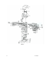
Detail A.......................................................................................................................................... 66
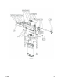
Detail B .......................................................................................................................................... 67
Detail C .......................................................................................................................................... 68
Detail D.......................................................................................................................................... 69
4
User Manual
INTRODUCTION
The printer is a high-performance, low-cost Direct Thermal/Thermal Transfer labeling systems.
Its user-friendly design and affordable price set a new standard for the Desktop Label Printer in
retail, office and industrial applications.
The printer is designed with the most efficient memory management technology - True Speed and
prints at a speed of 1 to 6 inches per second. When bundled with its smart printer driver, the user
can easily print out bar codes, texts and graphics from any editing application (e.g. CodeSoft,
BarTender) under Windows 95/98/2000, and NT. All popular bar codes and fonts are resident in
the printer memory to handle versatile applications.
The solid designed mechanism allows quick and easy media (paper) and ribbon loading. The
optional Peel and Present, and Cutter provide alternatives of fan-fold label and continuous paper
handling.
This printer is a compact, highly integrated, high performance and high resolution on-site labeling
system.
The User’s Manual will help you understand basic operations of the printer such as set-up,
installation, configuration and maintenance. Before reading the manual you should first identify
your printer model. The printer model name is located on the back of the printer on its product
label.
User Manual
5
MODEL OVERVIEW
Models
The Fastmark 600 series supports several models and emulations:
Fastmark 602 (203 dpi – PPLA or PPLB emulations)
Fastmark 603 (300 dpi – PPLA or PPLB emulations)
Fastmark 612 (203 dpi – PPLZ emulation)
These models are similar in many ways. Throughout this manual instructions and illustrations
applying to a particular model will be labeled accordingly otherwise the instructions apply to all
models.
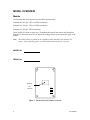
Note: The model number is printed on the compliance label attached to the bottom of the
printer. After unpacking please record the model number below for reference.
MODEL No:
SERIAL No:
Model No:
And
Serial No:
Figure 1 – Model and Serial Number Location
6
User Manual
Model Features
For detailed feature specifications, please refer to Appendix A. Below is a brief summary of
printer features:
Standard Features
q
Popular Emulations. The printer offers multiple emulations. These emulations allow
the user to select one of three-printer languages thus allowing exceptional printing
abilities with flexible programming abilities. Because it is designed as both a printing
and multiple programming languages, it is extremely powerful, flexible, and efficient
compared to any other thermal printer language on the market today.
•
PPLA emulation
•
PPLB emulation
•
PPLZ emulation
q
Powerful Windows Drivers are included that enable use with Windows applications
q
Serial and Parallel ports standard
q
Clamshell design for simplified media and ribbon loading
q
Reflective media detection sensor
q
Ribbon out sensor
q
Center Justified Media printing with removable media spindle.
q
Rugged print mechanism with high impact ABS housing
User Manual
7
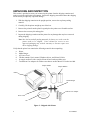
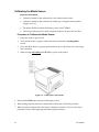
UNPACKING AND INSPECTION
This section is provided to assist you in removing the printer from the shipping container and
setting it up in the application environment. Inspect the shipping carton and contact the shipping
carrier directly to report any suspected damage.
1. With the shipping container in the upright position, remove the top foam packing
material.
2. Carefully, lift the printer straight up out of the box.
3. Remove the printer from the plastic bag and place the printer on a flat stable surface.
4. Remove the accessory kit and supplies.
5. Inspect the shipping container and the printer for any damage that may have occurred
during shipping.
Note: Save the box and all packing materials for future use, in the event the
printer needs to be shipped. Units returned for service in nonapproved packaging may void the warranty or increase repair costs
due to shipping damage.
Verify that the printer box contains the following materials when unpacking:
a.
b.
c.
d.
e.
f.
Printer
Media Hanger
AC Power Cord
CD that contains User's manual, Windows drivers, and Printer Utilities
A sample media roll with a sample ribbon roll and a take-up ribbon core
Two Ribbon Core adapters for ribbon cores that are smaller than 4.325 inches in width.
Sample Media
Sample Ribbon
Printer
Media Hanger
Ribbon Core Adapter
Power Cord
CD
Figure 2 – Shipped with Printer
8
User Manual
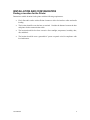
INSTALLATION AND CONFIGURATION
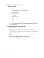
Finding a Location for the Printer
Determine a suitable location for the printer with the following requirements:
•
Find a flat stable surface with sufficient clearance to allow for interface cables and media
loading.
•
The location should be near the host or terminal. Consider the distance between the host
and printer for the communication cable.
•
The location should be free from excessive direct sunlight, temperature, humidity, dust,
dirt, and debris.
•
The location should be near a grounded AC power receptacle wired in compliance with
local ordinances.
User Manual
9
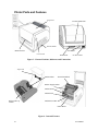
Printer Parts and Features
Top Cover
External Media Slot
Power Switch
Media Out Slot
Serial Port
Cover Lock
Parallel Port
AC Power Port
Figure 3 – External Switches, Indicators and Connections
Top Cover
Media Holder
Thermal Printhead
Ribbon Supply Holder
Media Guides
Media Sensor
Ribbon Take-up
Holder
Media Present Bar
Platen Roller
Figure 4 – Internal Features
10
User Manual
Connecting the Power Cord
1. Ensure the printer power switch is Off, “O”.
2. Connect the power plug to the back of the printer.
3. Connect AC power plug to a suitable AC source.
4. Connect either a Centronics Parallel or RS-232 Cable.
Figure 5 – Power Connection
User Manual
11
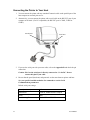
Connecting the Printer to Your Host
1. You can connect the printer with any standard Centronics cable to the parallel port of the
host computer or network print server.
2. Alternatively, you can connect the printer with a serial cable to the RS-232C port of your
computer or terminal. (For PC compatibles, the RS-232C port is COM1, COM2 or
COM3.)
Parallel Port
Serial Port
Figure 6 – Communication Cable
3. If you use the serial port with your own cable, refer to the Appendix B and check the pin
connection.
Caution: Pin 9 on the serial port is directly connected to +5 volts DC. Do not
connect this pin in your cable.
4. Be sure that the speed (baud rate) and protocols are the same between printer and host.
See your specific installed emulation for commands to set the Serial
Communications parameters.
Default serial port settings:
12
Speed (baud rate)
9600
Data format
1 start bit, 8 data bits and 1 stop bit
Parity
None
Handshaking (Flow control)
XON/XOFF and RTS/CTS
User Manual
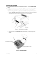
Loading the Ribbon
Direct Thermal Media does not require the installation of a ribbon. Skip to the Loading Media
section.
Thermal Transfer media requires an installed ribbon. Follow the below instructions for ribbon
installation. Note: The media and the ribbon must be compatible. Also the print head
temperature setting may need to be adjusted (see emulation commands for heat adjustments).
1. Open the Top Media Access Cover by pressing in on both Cover locks (one on each side
of the printer) and lifting the top cover until it rests in the vertical position.
Cover Lock
Figure 7 – Top Media Cover Latches
2. Press down on the two Print Head Latches (labeled PUSH) to unlock the print head
module.
Print Head Module
Print Head Release Latch
Print Head Release Latch
Figure 8 – Print Head Latches
User Manual
13
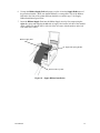
3. Rotate the Print Head Module to the vertical position.
4. Verify that the Ribbon Supply Core and the Ribbon Take-up Core have two slots on
the left side of the core 180-degree’s apart. If the width of the ribbon is less than the
minimum core width or if no slots are present, insert one of the supplied Ribbon Core
Adapters into each ribbon core.
5. The Slots in the Ribbon Core should mate to the Notches in the Left Ribbon Supply
Holder and the Left Take-Up Holder. If using the Ribbon Core Adapter, the adapter’s
notches will mate with the slots in the Ribbon Holders.
Note: The notches are the drive mechanism and the ribbon out reporting for the ribbon. If the
slots for the Ribbon Core are not correct, contact your ribbon supplier to obtain the correct
ribbon. If you need the Ribbon Core Adapter, contact your printer supplier.
Ribbon Supply Holder
Ribbon Supply Core and
Take-up Core
Ribbon Notch Location
Core Slots
Figure 9 – Ribbon Holder Notches and Ribbon Core Slots
14
User Manual
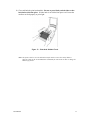
6. Unwrap the Ribbon Supply Roll and prepare to place it into the Supply Holder area of
the print head module. Make sure that the Ribbon is coming off the Top of the Ribbon
Roll and to the front of the printer (Ribbon should be a wound-in type). See Supply
Ribbon Installation figure below.
7. Insert the Ribbon Supply Core into the Ribbon Supply Area by first compressing the
right side spring and snapping the left side of supply core into the left side of the notched
wheel. Make sure that the slots in left side of the core mate with the notches on the left
side ribbon drive wheel.
Ribbon Supply Roll
Right Side Spring Holder
Ribbon Take-Up Roll
Figure 10 – Supply Ribbon Installation
User Manual
15
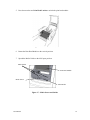
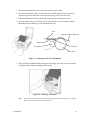
8. Loop the ribbon over the Print Head Module. Insert the Take-up Core into the Take-Up
Area by first compressing the right side spring and snapping the left side of take-up core
into the left side of the notched wheel. Make sure that the slots in left side of the core
mate with the notches on the left side ribbon drive wheel.
Take-Up Core
Ink Side of the Ribbon
Print Head Module
Figure 11 – Ribbon Take-Up Installation
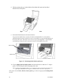
9. To remove any slack in the ribbon, manually rotate the Take-up Core Wheel until the
ribbon from the Supply Holder is snug around the Print head Module and onto the Takeup Core.
Figure 12 – Ribbon Installation
16
User Manual
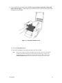
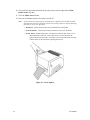
10. Close and latch the print head module. Be sure to press firmly on both sides so that
both latches clink into place. If either latch is not clicked into place it will cause the
media to not feed properly or print light.
Figure 13 – Print head Module Closed
Note: The printer must be set to the Thermal Transfer mode to ensure the end of ribbon is
detected. Refer to the section Emulation Commands for instructions on how to change the
Media Type feature.
User Manual
17
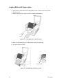
Loading Media
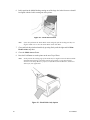
1. Open the Top Media Access Cover by pressing in on both Cover locks (one on each side of
the printer) and lifting the top cover until it rests in the vertical position.
Cover Lock
Figure 14 – Top Media Cover Latches
2. Remove the Media Hanger from the printer.
3. Remove one side of the Guides from the Media Hanger and slide the Media Roll onto the
Media Hanger, then reinstall the removed Guide.
4. Place the Media Hanger with roll of media into the appropriate slots on the printer and
centered the media in the printer.
Figure 15 – Media Roll Installation
18
User Manual
5. Press down on the two Print Head Latches to unlock the print head module.
Figure 16 – Print Head Latches
6. Rotate the Print Head Module to the vertical position.
7. Spread the Media Guides to their full open position.
Media Guides
Print Head Module
Media Sensor
Platen Roller
Figure 17 – Media Sensor and Guides
User Manual
19
8. With the printing side up, feed the Media off the Media Roll under the Print Head
Module and over the platen.
Figure 18 – Loading Media over Platen Roller
9. Position the Media Sensor to the desired location.
To position the Media Sensor examine the back of the Media Stock. As the media is
pulled through the printer position the sensor to avoid holes or preprinted information on
the back of the stock. These may cause incorrect top of form alignment. Typical media
stock backing is blank, therefore position the sensor in the middle of the stock.
Media Guides
Media Sensor
Figure 19 – Positioning Media Guides and Sensor
10. Close the Right and Left Media Guides until the Media Stock is under the “U” shaped
guides. This will keep the stock from going side to side.
Note: The Right and Left Media Guides are ‘U’ shaped parts that are located at the bottom of the
paper path. Both Guides move together to hold the stock in the Center of the printer.
If the printer has the Peeler, Pinch or Cutter options go to either the appropriate Loading Media
sections.
20
User Manual
11. Close and latch the print head module. Be sure to press firmly on both sides so that both
latches clink into place. If either latch is not clicked into place it will cause the media to not
feed properly or print light.
Figure 20 – Print head Module Closed
12. Close the Top Media Cover.
13. Press the Feed Button to correctly position the next Top of Label.
Note:
User Manual
The first time media is installed, the Media Sensor must be calibrated. After the first
calibration no further calibration is required unless the media type (length, color,
backing material, etc.) is changed or irregular feeding occurs. Refer to the section
Calibrating Media Sensors for instructions on how to calibrate the media sensor.
21
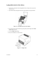
Loading Media with Peeler option
1. Install media as indicated in the Loading Media Section. Return to these steps when
directed to do so.
2. Remove about the first 6 inches of Labels from the media Backing.
Figure 21 – Label Removal for Peeler Option
3. Make sure the leading edge of the Media Backing has a straight edge.
4. Pull down the Peeler Latch.
Peeler Latch
Figure 22 – Straight Edge and Peeler Latch
22
User Manual
5. Position the Media Backing out of the printer and over the Peel Bar.
6. Push the Media Backing in the slot just under the Peel Bar and between the front cover.
Continue to push the stock until it comes out of the larger slot in the front cover.
7. If the Media Backing will not push through, then press the Feed button one time.
8. Once the media comes out of the larger slot, gently roll the excess media back onto the
Media Roll until the Backing is snug around the Peel Bar.
Label
Media Stock from Media Roll
Backing
Peeler Roller
Peeler Bar
Platen Roller
Figure 23 – Feeding into the Peeler Mechanism
9. In this position the Media Backing coming out of the large slot in the front cover should
be aligned with the Labels coming out of the printer.
Figure 24 – Backing Exit Position
Note:
User Manual
If not, then pull down the Peeler Latch and gently pull the backing until they are aligned.
Make sure to close the Peeler Latch when done.
23
10. Close and lock the print head module by pressing firmly until the right and left Print
Head Latches snap shut.
11. Close the Media Access Cover.
12. Press the Feed Button until the first label is peeled off.
Note:
In this position the trailing edge of the media may be caught between the Platen and the
Printhead and will not be removable until the next printing. Make sure that the following
functions are set in your application:
ü BackFeed – Tell the printer to move the printed label out of the printer
ü Present Distance – This function tells the printer how far to move the media
ü Peeler Sensor – Enable this function. The printer will monitor this sensor to see if
the printed label is removed. If the sensor does not see the label then the
printer will print the next label. If the label is not removed the printer will wait
until the sensor is uncovered before printing the next one.
Figure 25 – Peeler Option
24
User Manual
Loading Media with Pinch Roller Only option
This procedure should only be used with labels that do not have sticky back. This option increases the
surface of the media around the platen, thus resulting in extra pulling force.
Note: This option expects that one-inch of the leading edge of the media will not be
printed upon.
1. Install media as indicated in the Loading Media Section. Return to these steps when
directed to do so.
2. Pull down the Pinch Roller Latch.
Pinch Roller Latch
Figure 26 – Pinch Roller Latch
3. Push the Media between the Pinch Roller and the Platen Roller. Continue to push the
stock until it comes out of the larger slot in the front cover.
4. If the Media will not push through, then press the Feed button one time.
5. Once the media comes out of the larger slot, gently roll the excess media back onto the
Media Roll until the Backing is snug around the Platen Roller.
Figure 27 – Feeding into the Pinch Mechanism
User Manual
25
6. In this position the Media Backing coming out of the large slot in the front cover should
be aligned with the Labels coming out of the printer.
Figure 28 – Media Exit Position
Note:
If not, then pull down the Pinch Roller Latch and gently pull the backing until they are
aligned. Make sure to close the Pinch Roller Latch when done.
7. Close and lock the print head module by pressing firmly until the right and left Print
Head Latches snap shut.
8. Close the Media Access Cover.
9. Press the Feed Button to set the printer to the next Top of Form.
Note:
In this position the trailing edge of the media may be caught between the Platen and the
Printhead and will not be removable until the next printing. Verify that all Peeler
Features in the Setup Menu are properly set (BackFeed, Present Distance, and Peeler
Sensor) for your application.
Figure 29 – Pinch Roller Only Option
26
User Manual
Loading Media into the Cutter Option
1. Install media as indicated in the Loading Media Section. Return to these steps when
directed to do so.
2. Push the Media Stock through the slot on the Cutter Module near the platen Roller.
Figure 30 – Inserting Labels in the Cutter Option
10. Close and lock the print head module by pressing firmly until the right and left Print
Head Latches snap shut.
11. Close the Media Access Cover.
12. Press the Feed Button to cut the first label.
Figure 31 – Cutting Labels
User Manual
27
Calibrating the Media Sensor
Important information:
§
Calibration should be done when media is first installed in the printer.
§
Calibration should be done each time the media type is changed (sensing method,
Length, color, etc)
§
The printer should be calibrated following a reset of the E2PROM.
§
Following a calibration feed a label to align the printer to the top of the next label.
Procedure to Calibrate the Media Sensor
1. Ensure the printer is powered off.
2. Verify that the media is properly loaded and routed as detailed in Loading Media
section.
3. Verify the Media Sensor is properly positioned directly over the object to be sensed (gap,
hole, and notch).
4. While pressing and holding the PAUSE key, power on the printer.
Figure 32 – Calibration of the Media
5. Release the PAUSE button when the media begins to feed.
6. When feeding stops the printer has completed the Label Sensor Calibration procedure.
7. When the printer completes the Label Sensor Calibration procedure it will save the related
parameters (sensor, label length, gap/notch/hole length) to memory.
28
User Manual
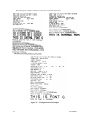
Printing the Configuration Label
Important information:
§
The configuration label indicates the current setting and parameters of the printer.
Some of the items displayed in this label are:
Current Firmware revision (Top line of the label).
RS-232 parameters,
Media type (DT/TT),
Label Count,
Media Sensor Level,
Resident font types,
etc.
§
Following printing of the configuration page the printer may be in a diagnostic
(hexadecimal) mode. To exit the diagnostic mode, turn the power off.
§
The printed configuration will be different depending upon the emulation loaded, and
current value settings.
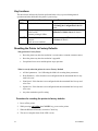
Procedure for printing a Configuration Label.
1. Power off the printer.
2. Make sure that the installed media is 4 inches wide and 20 inches in length (five 4x4
labels or four 4x6).
The printer will first do a label calibration (12 inches in length), then print a configuration label
(approximately 5 inches in length).
3. Verify that the media is properly loaded and routed as detailed in Loading Media
Section.
4. While pressing and holding the FEED key, power on the printer.
5. Continue to hold the FEED key until the printer begins to print the configuration label,
then you may release the FEED key.
User Manual
29
The following are examples and may not reflect the actual printed font types.
Figure 33 – Configuration Print Samples
30
User Manual
KEYPAD OPERATION
The Front Panel keys serve multiple functions. Refer to the following tables for their
specific functions.
FEED
PAUSE
CANCEL
£ READY
£ MEDIA
£ RIBBON
Figure 34 – The Printer’s Front Panel
LED Description
m
m
m
User Manual
LED
Function
READY ON: Printer is powered on and ready for operation.
OFF: Printer is receiving data, or in a Fault condition.
Steady Blinking: Error has occurred.
MEDIA ON: Printer is online and ready to receive data.
OFF: Printer is off line and not ready to print. Typically following
pressing of the Pause key.
Steady Blinking: Media Error. (Ready LED will also be blinking)
RIBBON ON: Print is set for Thermal Transfer Mode.
OFF: Printer is set for Direct Thermal Mode.
Steady Blinking: Ribbon error occurred. (Ready LED will also be
blinking)
31
Key functions
The table below indicates the function performed when a key is pressed during normal
operation and when held while the printer is powered up.
Key
FEED
Normal Operation
Feeds a Label
PAUSE
Stops printing and places the
printer on line.
Resumes printing if offline.
CANCEL Pauses and deletes the current
print job.
Clears an error condition.
Pressed during Power Up
The printer generates a configuration label.
See Printing the Configuration Label for
details.
The printer performs a Calibration test. See
Calibration of Media Sensor for details.
Reset the settings at E2PROM. See Resetting
the Printer for details
Resetting the Printer to Factory Defaults
Why perform a Factory Reset:
§
Reset the printer any time the emulation is switched (PPLA to PPLB, or PPLB to PPLA).
§
Reset the printer any time the emulation is upgraded.
§
Unexplained errors occur and the printer stops operation.
What is reset by when the printer is reset to Factory Default
§
All label parameters. See Calibrating the Media for resetting these parameters.
§
Heat (Darkness). If this function is not configured with the transmitted label it may
need to be reset.
§
Print Speed. If this function is not configured with the transmitted label it may need
to be reset.
§
Symbol Set. If this function is not configured with the transmitted label it may need
to be reset.
§
Any other emulation specific setting.
Procedure for resetting the printer to factory defaults
1. Power off the printer.
2. While pressing and holding the CANCEL key, power on the printer.
3. When the Ribbon LED blinks, release the Cancel key.
4. The reset is complete when all the LED’s are on.
32
User Manual
Windows Drivers
The provided CD contains printer driver can be used with applications under Windows
XP/2000/98/95, and Windows NT. These drivers can be used with popular software
applications, such as Word, to print labels as long as the applications are using the
Windows Print Manager.
Information:
§
Follow the instructions on the CD for Proper Installation Procedures.
§
Before installation, make sure you have “User right’s” up to the level of
‘Administrator'.
§
There are two Basic Drivers for the Printers:
Ø
Ø
Fastmark 200dpi
Fastmark 300dpi
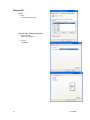
Installing Windows Driver
1. From the task bar select Start->Settings->Printers.
displayed.
The printer’s folder should be
2. Double click the Add Printer icon.
§ The Add Printer Wizard dialog should be displayed.
§ Click the Next button.
3. Select the Local printer option and click the Next button.
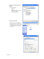
4. From the Manufacturers list dialog click the Have Disk button.
5. Using the Browse button go to the location of the driver files and click OK.
Select the proper Directory for installation:
§ WIN98
§ WIN2000
§ NT4.0
§ WIN XP
6. From the Install from Disk dialog, select the displayed *.inf file and click OK.
7. The Add Printer Wizard should now display the available models for this driver. Select
the model you wish to install and click Next.
8. Select the desired communication port. If the printer is attached to the Parallel port then
select the LPT port. If attached to the serial port then select the COM port. Your PC
may have multiple ports available. Make sure that you select the appropriate port that
your printer is attached to.
9. When you have answered all the questions, Click the Finish button on the Completing the
Add Printer Wizard. If a Hardware Installation message is displayed, click Continue
Anyway. A printer icon should be added to the list of printers. If a message is displayed
indicating the installation could not be completed, you may need to change the security
level for installing drivers and repeat the installation process.
User Manual
33
Notes:
34
§
If you have set the printer as the default printer, the driver is now ready for use.
§
If you did not set the printer as the default printer, you can change the setting by right
clicking on the printers' icon and select 'Set as Default' from the dialog.
§
If you are updating an existing driver, it is suggested that you delete the old driver
first.
§
A Windows driver must be installed prior to installing Xbar.
§
Be sure to select they appropriate width model (2 inch, 3 inch, 4 inch or 6 inch
model). If you select a smaller width model than the printer all your applications will
be truncated at that width. Example: If the printer being used has a width of 6 inches
and the driver selected is for a 4 inch model, then only 4 inches of information will
be printed on the label.
§
A label printed using a Windows driver is printed using GDI graphics. The installed
emulation (PPLA, PPLB or PPLZ) is not used when printing using the Windows
driver. The Application or the Driver controls all printing.
User Manual
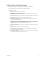
Setting the Printer’s Windows Parameters
After installing the driver, you can follow the path below to set parameters:
Start à Settings à Printers à Printer Name 200dpi à Properties
The parameters include:
§
Ports Select the I/O port to link with the printer.
§
Paper size Select the paper size on the menu. If there is no desired size, select “Custom”
(only in Win98/95/Me) to define the paper sizes.
§
Create a new size Define paper size in Win 2000/XP/NT4.0 under Fileà Server Properties.
§
Orientation Set portrait or landscape according to the print direction.
§
Paper source (Media type) T/T stands for thermal transfer (ribbon) mode and D/T for
direct thermal mode (without ribbon).
Labels typically have a specific beginning or Top-of-Label. This TOL is may be defined by a
GAP (blank space between labels) or a Black Bar (black line on the back or the media). A
Continuous roll is media without a defined break between labels.
§
Media choice (Darkness) sets the heat value or darkness. The darkness value ranges from
0 to 15.
§
Copies Designates the number of printed copies of each page.
§
More option (Accessory setting) When one of the mechanical options is installed, use
this to enable the cutter and peeler function.
§
Device options (Speed) Sets the printer speed. For 203dpi printers, the speed ranges from 2
to 6 IPS, for 300 dpi printers the range from 2 to 4 IPS.
User Manual
35
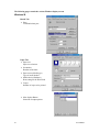
The following pages contain the various Windows display screens
Windows 98
Details Tab
Ø Ports
Communications port.
Paper Tab
Ø Paper size
Paper size selection
36
Ø
Orientation
Rotation of the label
Ø
Paper source (Media type)
Type of media loaded
Ø
Media choice (Darkness)
Heat setting for the Print Head
Ø
Copies
Number of copies to be printed
Ø
More Option Button
Selection of output options
User Manual
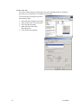
Device Option Tab
Ø
Print Quality
Print Speed selection. Note: Depending upon
density of label the printer will vary the print
speed to maintain print quality.
Creating User-Define Paper
Ø To define a Custom form click on the
Custom Paper Size.
User Manual
37
Windows 2000
Ports Tab
Ø Ports
Communications port.
General Tab
Ø Printing Preference Button
Layout and Paper/Quality
Ø
Print Test Page Button
Prints a sample label
Paper Quality
Ø
38
Determines the Media and Top-ofLabel method
User Manual
Layout
Ø
Orientation of label print
Advance Option Button
Ø
Ø
Ø
Ø
Ø
User Manual
Paper size
Copies
Media choice (Accessory setting)
Paper/Output (Speed)
Print quality (Darkness)
39
Create a new size
To create a custom label size requires the user to do so though the Server Properties.
Once the size is created then it is available for all printers.
To access the Server properties go to the
main Printer Folder.
Ø
Ø
Ø
Ø
Select the Server Properties (File tab).
Click on the Create a New Form box.
Fill in the Measurements
Name the form in the Form
Description line.
Ø Click on Save Form button.
40
User Manual
Windows NT 4.0
Ports
Ø Ports
Communications setup
General Tab – Documents Defaults
Advanced Tab
Ø
Paper size
Ø
Orientation
Ø
Paper source (Media type)
Ø
Copies
Ø
Media choice (Accessory setting)
Ø
Paper/Output (Speed)
Ø
Print quality (Darkness)
Create a new size
Please refer to the procedure to create a new size under
Windows 2000.
User Manual
41
Windows XP
Ports
Ø Ports
Communications setup
General Tab - Printing Preferences
Paper / Quality
Media type installed
Ø
Ø
42
Layout
Orientation
User Manual
General Tab - Printing Preferences
(continue)
Ø
Advanced Options
Paper size
Copies
Media choice (Accessory setting)
Paper/Output (Speed)
Print quality (Darkness)
Creating a new label size
Ø
Ø
Ø
Printer menu - Server Properties
Enter a form name for the new form
Modify the paper size in the specific
squares of the "Form description"
Ø click "OK"
User Manual
43
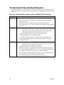
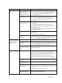
TROUBLESHOOTING AND MAINTENANCE
When the printer detects a malfunction or an abnormal condition occurs the READY LED
will begin to blink. The printer will also stop printing and communication with the host will
stop.
Check the following LED conditions when the READY LED is blinking.
LED
m READY
Error Condition and possible Cause and Correction
Blinking:
Ø The format or baud rate of the RS232 protocol is incorrect between the
printer and host.
Ø The cutter can not cut off the media, check the media and cutter.
Ø The printer buffer is full. Can be caused by the loaded soft fonts, graphics
or forms.
m MEDIA Blinking: Media Error. A reflective sensor under the media stock monitors the
media. If the media sensor does not see the media stock or if the next
Top-of-Label is not at the expected location or if the back of the
media stock absorbs the reflection this error may occur.
Ø Typically a Media OUT has occurred. Install a new media.
Ø Verify that Media Sensor is in proper position.
Ø Verify that a foreign substance does not cover the Media Sensor slot.
Ø Verify that the media stock have dark information printed on the back.
Ø Calibrate the printer.
m RIBBON Blinking: Ribbon error occurred. The printer monitors the motion of the Supply
roll. If the printer is set for Thermal Transfer and the Supply Roll
does not turn, then a ribbon error will occur.
Ø Typically the ribbon is out. Install a new ribbon.
Ø Ribbon has broken. Verify that the Heat and the Print Speed settings do
not result in burning the ribbon in two. Also, very large black lines that are
full length of the media may also cause the ribbon to separate.
Ø Does the Ribbon Supply and Ribbon Take-up Cores have notches on the
left side of the core. If not then use the adapter cores.
Ø Verify that the ribbon is being pulled by the Take-up roll.
44
User Manual
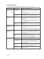
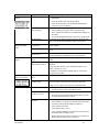
User Detected Errors
The following tables contain solutions other than user detected or visualized errors.
Description of Issue
No power or
LEDs are not ON
Media not feeding
properly
Possible Cause
Printer not attached to a
power source.
Possible Correcting Procedures
1. Verify Power Plug on back of printer is pushed firmly in.
2. Verify Power Adapter is connected to a known power
source.
3. See Maintenance Manual for procedure of verifying and
changing of the fuse.
Power Switch is not in
the on position.
1.
2.
Verify Switch is in the ‘1’ position.
Toggle switch to verify both off and on conditions.
Media Latches not
closed.
1.
2.
Open the Top Cover.
Verify Media is installed according to the Loading
Instructions.
Press firmly on the top of the Printhead Mechanism and
verify the both the right and left latches are locked.
Close the Top Cover.
3.
4.
Media is drifting to
the right as it comes
out of the printer.
Media not installed
correctly
Verify Media is installed according to the Loading
Instructions.
Media Guides not in the
proper position.
1.
2.
3.
Text prints off the
right of left side of
the media
Improper loading of the
stock.
1.
2.
Verify Media is installed under the media guides.
Verify that the right Media Guide is in the proper
Position. The media needs to be snug between the left
and right guides.
Width of stock is
incorrect.
1.
Verify that the width of the stock matches that of
previous roll. If not contact media supplier.
Verify that the label is centered properly on the backing
of the stock. If not contact media supplier.
2.
Printer feeds blank
labels before printing
User Manual
Open the Top Cover.
Verify Media is installed according to the Loading
Instructions.
Verify that the right Media is in the proper Position. The
media needs to be snug between the left and right guides.
Media is not Calibrated
Run Media Calibration procedure
Media not installed
under Media Guides
1.
2.
Verify Media is installed under the media guides.
Verify that the right Media Guide is in the proper
Position. The media needs to be snug between the left
and right guides.
Media Sensor not
functioning
1.
2.
Turn off the printer and remove the media.
Using a Swab dipped in Alcohol clean the Media Sensor.
See User’s Manual for location of sensor.
Backing of stock to
dark for media sensor
Verify that the stock matches that of previous roll. If not
contact media supplier.
45
Description of Issue
LEDs indicate Media
Out
Possible Cause
Media Latches not
closed. Or Media is too
far from the Media
Sensor to be detected.
Possible Correcting Procedures
1. Open the Top Cover.
2. Press firmly on the top of the Printhead Mechanism and
verify the both the right and left latches are locked.
3. Close the Top Cover.
Media Guide not in the
proper position.
1.
2.
Verify Media is installed under the media guides.
Verify that the right Media Guide is in the proper
Position. The media needs to be snug between the left
and right guides.
Media is not going flat
across the sensor.
1.
Verify Media is installed according to the Loading
Instructions.
Verify that the right Media Guide is in the proper
Position. The media needs to be snug between the left
and right guides.
Rewind the Media stock onto the supply roll until stock is
flat across the sensor.
2.
3.
Media not Calibrated
1.
2.
Printer prints a label
then continually feed
labels through the
printer.
No print on Label
Media Sensor needs to
be cleaned
1.
2.
Media is not Calibrated
Run Media Calibration procedure
Media Sensor not
functioning
1.
2.
Spacing between labels
is incorrect or does not
exist.
Verify that the stock matches that of previous roll. If not
contact media supplier.
Media Stock incorrect
Verify stock type (Direct Thermal or Thermal Transfer)
If Thermal Transfer Stock, add the appropriate Ribbon.
To Verify stock is Direct Thermal material, heat the material.
If the material turns color (Black) then stock is DT.
If DT media verify that the correct side is next to the print
head.
Verify printer will do a
Self Test
1.
Media installed
incorrectly
Verify Media installation using the Loading Instructions.
No communication
with attached host.
1.
2.
3.
Communication
parameters incorrect.
46
Verify Media is installed according to the Loading
Instructions.
Run the Calibration Procedure.
Turn off the printer and remove the media.
Using a Swab dipped in Alcohol clean the Media Sensor.
See User’s Manual for location of sensor.
Turn off the printer and remove the media.
Using a Swab dipped in Alcohol clean the Media Sensor.
See User’s Manual for location of sensor.
Power on the printer while holding the Feed button.
Send Data from a host system.
If LED blinks the printed is physically connected by the
cable.
Reset the Printer to Factory Defaults.
Reset the Printer to Factory Defaults. Then verify host and
printer communication parameters.
User Manual
Description of Issue
Vertical Streaks on
output
Possible Problem
Dirty printhead
Possible Correcting Procedures
1. Turn off power and open the Top Cover and Printhead
Mechanism.
2. Using an alcohol swab wipe the printhead.
3. Allow the alcohol dry, close the Printhead Mechanism,
close the Top Cover and retry.
Vertical line on all
printed samples.
1.
2.
3.
4.
Host indicates
PRINTER TIME
OUT
Data is sent but no
output.
Text cut off at top or
bottom of the label.
Poor Print Quality
Media Damage
Verify there are no nicks or burrs anywhere in the paper path
such as a scratched rail and that the media is not creased.
Communication cable
not attached
Verify communication (Serial or Parallel) is attached to both
printer and host.
Printer not turned on
Verify Printer’s power switch is in the on position and LEDs
are on.
Host transmitting out
incorrect port.
Verify that host is transmitting out the correct port.
Verify that Windows sending data to the proper location
Incorrect Windows
Driver
Verify that the Application is communicating to the correct
printer.
Incorrect emulation
installed in the printer
Verify the application is using PPLA, PPLB or PPLZ
emulation.
Verify the printer has the correct emulation installed. (Use
Printer’s Self test to verify).
If available, put the printer into HEX mode to verify data is
being sent to the printer.
Unprintable location on
label.
Verify that area on label is printable.
Text position too close
to label’s edge.
Text need to be at a minimum no closer than 0.1 (1/10th) of an
inch to the edge of the label, often called the Quiet Zone.
Adjust text to not print in the quiet zone around the label.
Verify Media stock
1.
2.
Change Media with Stock from another unopened box.
Verify that Stock is Direct Thermal material.
Verify Printhead
Latches are closed.
1.
2.
Open Top cover
Press firmly on the Printhead Mechanism and verify that
the right and left latches are locked.
Other Possible
Solutions
1.
2.
3.
4.
5.
6.
Verify type of media and ribbons are compatible.
Verify ribbon is not being used with direct thermal media.
Lower the print speed and adjust print darkness.
Verify print head is clean.
Verify platen roller is clean.
Verify media and ribbons are both loaded as described in
media and ribbon loading sections.
Replace print head if print out continues to be streaked or
missing and all of above does not resolve.
7.
User Manual
Verify line occurs after pressing the Feed Button.
Verify nothing in the paper path is causing the line.
If not, replace the Printhead. See Maintenance Manual for
Procedure.
If replacing Printhead does not correct issue, replace PCB.
47
Peel and Present Sensing
Description of Issue
Printer prints multiple
labels before pausing
Printer does not
Retract the label after
it is taken.
Printer Retracts media
only after top cover is
lifted.
Does not print the next
label
Possible Problem
Top Cover is not closed.
Possible Correcting Procedures
Close Top Cover.
Sensor is not working
properly
1.
2.
Clean Present Sensor
Recalibrate the Present Sensor. See Maintenance Manual
for procedure.
Printed label has not
been removed.
1.
2.
3.
Remove previously printed label.
Open and close top cover.
If label retract, Clean the Present sensor or recalibrate the
sensor.
Label backing is not
tight around the Peel
Bar.
1.
2.
Properly install the media stock.
Make sure to rewind the stock onto the supply roll until
the backing is tight around the peel bar.
Sensor is in the incorrect
position.
Verify that the sensor in pointing down to the media stock.
Sensor is dirty.
1.
2.
Sensor is not plugged
into main PCB
See Maintenance Manual for installation of Peel and Present
option.
Sensor is faulty.
Replace sensor and cable. See Maintenance Manual for
Procedure.
Backing of the media is
not tight across the Peel
Bar.
1.
2.
Media not retracted and
ready for next print and
label is removed.
Open Top Cover.
1. If media reverse feeds and prints the next label, clean the
present sensor.
2. The Present sensor is located on the top cover. With the
Top Cover open, use a Swab dipped in Alcohol to clean
the sensor.
3. Verify that the Sensor is pointing down to the paper.
Printed label not
removed.
1.
2.
3.
48
Clean Present Sensor
Recalibrate the Present Sensor. See Maintenance Manual
for procedure.
Verify Media installation using the Loading Instructions.
Make sure following installation that the supply roll is
rewound so that the media is not loose across the Peel
Bar.
If the previous label has been removed and the printer
does not reverse, Open and close the top cover.
If label retract, Clean the Present sensor or recalibrate the
sensor.
If calibrating the Present Sensor does not correct the
problem, then printer may need to be serviced.
User Manual
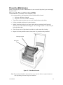
Preventive Maintenance
Before performing any Preventive Maintenance be sure to turn off the printer's power and unplug
the power cable.
Cleaning the Thermal Print Head (TPH)
It is recommended at a minimum that the Print Head should be cleaned:
• Each time a Ribbon is changed.
• Each time a new roll of media is installed.
1. Turn off the printer, open the top cover, and if installed remove the ribbon.
2.
Lift the print head module to the vertical position.
3.
Rub the print head with a piece of cotton, which has been moistened with Isopropyl
Alcohol, or use a thermal head-cleaning pen. The Cleaning Location is a Glass Area just
below the Metal edge.
4.
Check for any traces of discoloration or adhesive on the cotton after cleaning.
5.
Repeat if necessary until the cotton is clean, after it is passed over the print head.
Cleaning Location
Print Head
Figure 35 – Print Head Location
Note: The print head should be cleaned at least every time the ribbon is replaced and more
often depending on actual usage and conditions.
User Manual
49
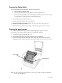
Cleaning the Platen Roller
It is recommended that the platen roller should be cleaned when:
• Excessive dusty condition exists.
• Following a media jam where the adhesive comes in contact with it.
• Because of the squeezing process of feeding the media the roller can become sticky
from the adhesive being pressed out from behind the label.
Turn off the printer and open the top cover.
2. Lift the print head module to the vertical position.
1.
3.
Rub the full length of the platen available with a piece of cotton, which has been
moistened with Isopropyl Alcohol.
4.
Manually rotate the platen and repeat step 3 until the entire platen has been cleaned.
Cleaning the paper sensor
It is recommended that the Paper Sensor be cleaned regularly if exposed to a dusty
environment. This will prevent false paper OUT or paper IN conditions.
1. Turn off the printer and open the top cover.
2.
Remove paper dust by blowing using compressed air or vacuuming.
3.
Clean the two Paper Sensor LED's with cotton stick, which has been moistened with
Isopropyl Alcohol. Sensor is located in the small slot that is movable from side to side.
Media Sensor
Platen Roller
Figure 36 – Platen Roller and Media Sensor
Note: The roller should be cleaned whenever it has been in contact with foreign materials
such as dust or adhesives
50
User Manual
Cleaning the Paper Compartment
It is recommended that the Paper Compartment be cleaned regularly if exposed to a dusty
environment. This will keep dirt and dust from contaminating or damaging your printer (Print
Head and Platen).
1.
Turn off the printer and open the top cover.
2.
Remove paper dust by blowing using compressed air or vacuuming.
3.
Clean the paper compartment with cotton, which has been moistened with mild detergent.
User Manual
51
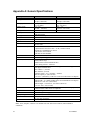
Appendix A: General Specifications
Specifications
Printing method
Printing resolution
Printing speed
Printing length
Printing width
Memory
CPU type
Media sensor
Display
Operation interface
Communication interfaces
Fonts (Emulation Dependent)
2D Barcodes
Graphic
Software (Emulation)
Media
Ribbon
Mechanism information
Weight
Power source
Agency listing
Operation environment
Optional items
Fastmark 602 and 612
Fastmark 603
Direct thermal or Thermal Transfer
203 dpi (8 dots/mm)
300 dpi (12 dots/mm)
2 ~ 6 ips
2 ~ 4 ips
(51~150 mm/s)
(51~ 102 mm/s)
0.4” ~ 43”
0.4” ~ 14”
(10 mm ~ 1092 mm)
(10 mm ~ 355.6 mm)
Max 4” (101.6 mm)
Max 4” (101.6 mm)
2MB DRAM
1MB Flash ROM
32 bit RISC microprocessor
Reflective (Movable)
Three LED indicators
Three Buttons
Centronics parallel
RS-232 serial
Int’l character sets standard
5 alpha-numeric fonts from .049”~ .23”H (1.25mm~6.0mm)
All fonts are expandable up to 24x 24
4 direction 0º~270º rotation
Soft fonts are downloadable
Maxicode, PDF-417, Data Matrix
PCX bit map, GDI graphics
PPLA or PPLB Language
PPLZ (FM612 only)
Windows Driver (Win 98/2000/NT/XP)
Label editing software – Xbar Lite
Roll-feed, die-cut, continuous, fan-fold, tags, ticket in thermal paper or
plain paper and fabric label
Max width 4.3” (110 mm)
Min width 0.6” (15 mm)
Thickness .0025”~. 01” (.0635mm ~. 254mm)
Max roll capacity 6” (OD 152 mm)
Core size 1” (ID 25mm) (3” ID Core can be used with media core adapter)
Wax, Wax/Resin, Resin (inside costing)
Ribbon width – 4” (smaller widths can be used with Ribbon Core adapter)
Ribbon roll – max 2.67” (OD 68 mm)
Ribbon length – re-sin 300 m , wax 360 m (OD 68 m)
Core size - ID 1” core (25 mm)
Built-in Tear off bar, front-open cover, clear window, fan fold paper slot,
wound-in ribbon, TPH carrier not adjustable.
9.3 lbs (4.2 kgs)
Auto Sensing Power supply (90 ~ 250 VAC)
CE, UL, CUL, FCC class A, CCC
40ºF ~ 100ºF (4ºC~38ºC)
10~90% non condensing
Cutter, Dispenser kit, Real time clock card
Note: Fonts, Graphics, Character sets and Barcodes will differ between PPLA, PPLB and PPLZ
emulations.
52
User Manual
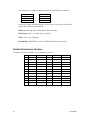
Appendix B: INTERFACE SPECIFICATIONS
This appendix presents the serial and parallel interface specifications. These specifications
include pin assignments, protocols and detailed information about how to properly interface your
printer with your host or terminal. The Serial ports Communication protocol can only be changed
through the installed emulation.
Serial Interface
Pin Configuration
The RS-232 serial interface uses a female, DB-9 connector.
Pin
Direction
Definition
1
Tied to in 6
Not used
2
In
Receive Data (RxData)
3
Out
Transmit Data (TxData)
4
No connection
5
Logic Ground
6
Tied to pin 1
Not used
7
Out
Request to Send (RTS)
8
In
Clear to Send (CTS)
9
Out
+5V
Note: Pin 9 is reserved for Keyboard Device Unit (KDU) only, do not connect this pin if you are using
a general host like a PC.
Connection With Host
Host 25S
Printer 9P
Host 9S
(PC or compatible)
DTR 20
DSR 6
TX 2
RX 3
CTS 5
RTS 4
GND 7
………..1 DSR
………..6 DTR
………..2 RX
………..3 TX
………..7 RTS
………..8 CTR
………..5 GND
Printer 9P
(PC or compatible)
DTR 4
DSR 6
TX 3
RX 2
CTS 8
RTS 7
GND 5
………..1 DSR
………..6 DTR
………..2 RX
………..3 TX
………..7 RTS
………..8 CTS
………..5 GND
Three Wire Connection
This method is the simplest method of connecting the printer to a host or terminal. This
method requires Software Protocol Handshaking (XON/XOFF flow control).
Host 25S
Printer 9P
Host 9S
(PC or compatible)
(PC or compatible)
TX 2
RX 3
GND 7
pin 4
pin 5
pin 6
pin 20
TX 3 ………..
RX 2 ………..
GND 5 ………..
pin 4
Pin 6
Pin 7
Pin 8
User Manual
……….. 2 RX
……….. 3 TX
……….. 5 GND
Printer 9P
2 RX
3 TX
5 GND
53
The simplest way to connect to other hosts (not PC compatible) or terminals is:
Printer
Pin 2- RxData
Pin 3- TxData
Pin 5- Ground
………
………
………
Terminal/Host
TxData
RxData
Ground
In general as long as the data quantity is not too large or you use Xon/Xoff as flow
control, there will be no problem at all.
Baud rate: 600, 1200, 2400, 4800, 9600, 19200 and 38400.
Data format: always 7 or 8 data bits; 1,2 stop bit.
Parity : none, even, odd parity.
Handshaking : XON/XOFF as well as CTS/RTS (hardware flow control).
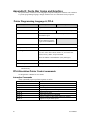
Parallel (Centronics) Interface
The parallel port uses a standard 36-pin Centronics connector.
54
Pin
Direction
Definition
Pin
Direction
Definition
1
In
/STROBE
13
Out
SELECT
2
In
Data 1
14,15
3
In
Data 2
16
-
Ground
4
In
Data 3
17
-
Ground
5
In
Data 4
18
NC
6
In
Data 5
19 to 30 -
Ground
7
In
Data 6
31
NC
8
In
Data 7
32
9
In
Data 8
33 to 36 -
10
Out
/ACK
11
Out
BUSY
12
Out
PE
NC
Out
/Fault
NC
User Manual
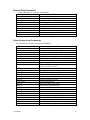
Appendix C: ASCII TABLE
The following table may be used to determine HEX values of ASCII characters. For example the
character A is hex 41 commonly shown as 0x41H.
0
0
NUL
1
SOH
2
STX
3
1
XON
XOFF
4
5
NAK
3
4
5
6
7
0
@
P
`
P
!
1
A
Q
a
Q
“
2
B
R
b
R
#
3
C
S
c
S
$
4
D
T
d
T
%
5
E
U
e
U
6
ACK
&
6
F
V
f
V
7
BEL
‘
7
G
W
g
W
8
BS
(
8
H
X
h
X
)
9
I
Y
i
Y
*
:
J
Z
j
Z
+
;
K
[
k
{
9
A
LF
B
User Manual
2
ESC
C
FF
,
<
L
\
l
|
D
CR
-
=
M
]
m
}
E
SO
RS
.
>
N
^
n
~
F
SI
US
/
?
O
_
o
DEL
55
Appendix D: Fonts, Bar Codes and Graphics
The specifications of fonts, bar codes and graphics depend on the printer emulation. The emulation
is a printer programming language, through which the host can communicate with your printer.
Printer Programming Language A, PPLA
Specification
203dpi Printers
300dpi Printers
General fonts
7 alpha-numeric fonts, OCR A and OCR B
ASD smooth fonts
6, 8, 10, 12, 14 and 18 points 4, 6, 8, 10, 12, 14, and 18 points
Symbol sets for smooth fonts
USASCII, UK, German, French, Italian, Spanish, Swedish, and
Danish/Norwegian
Courier fonts
8 symbol sets (PC, PC-A,
PC-B, EAMA-94, Roman ,
Legal, Greek and Russian)
Soft fonts
Downloadable PCL fonts
Font expandability
1x1 to 24x24
Bar code types
Code 39, Code 93, Code 128/subset A,B,C, Codabar, Interleave 2
of 5, UPC A/E/2 and 5 add-on, EAN-8/13, UCC/EAN-128,
Postnet, Plessey, HBIC, Telepen and FIM.
MaxiCode PDF417 and DataMatrix (2D symbologies).
Graphics
PCX, BMP, IMG and HEX formats
Stand-alone operation without host
Fastkey
Notes: As the font board and flash modules use the same connector they cannot function
simultaneously.
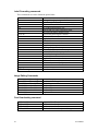
PPLA Emulation Printer Control commands
See Programmer’s Manual for more details.
Interactive Commands
These commands expect a printer response or action
Interactive Commands
Command
<SOH>#
<SOH>A
<SOH>B
<SOH>D
<SOH>E
<SOH>F
56
Description
Resets the printer
Requests a printer status from printer
Toggles pause status
Disable the interaction command
Requests a status of how many labels are queued
Requests a 1 byte status report
User Manual
Printer Editing Commands
These commands are saved into the EEPROM
<STX>KI7n
Sets Media Type (DT/TT)
<STX>KI8n
Sets Baud Rate
<STX>KI9bdpt
Sets Baud Rate, Databits, parity, stop bits
<STX>KI<m
Sets symbol set for smooth fonts
<STX>KIXnnnn
Sets label length for continuous label
<STX>KI0n
Sets cut mode
<STX>KI5nn
Sets the gap distance
<STX>KI;n
Sets control code set
<ESC>KI;n
Sets offset value for cutting or peeling
<ESC>KI:n
Sets horizontal shift position
<ESC>@0
Clears Flash memory
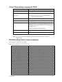
Printer System Level Commands
These commands will not be saved into the EEPROM
<STX>AwmmddyyyyhhMMjj
<STX>a
<STX>cnnnn
<STX>Dnnnnnnn
<STX>Ennnn
<STX>e
<STX>fnnn
<STX>G
<STX>Imbfnnn...n
<STX>J
<STX>j
<STX>KQ
<STX>L
<STX>Mnnnn
<STX>m
<STX>n
<STX>Onnnn
<STX>P
<STX>Q
<STX>qn
<STX>r
<STX>Sn
<STX>T
<STX>Unncccc
<STX>Vn
<STX>v
<STX>Wn
<STX>xmtn…n
User Manual
Sets date and time into the RTC
Requests a <RS> following printing of a label
Sets continuous label length
Clears the memory contents
Sets copy count
Select Gap Media sensing
Sets present position and automatic backfeeding
Prints Stored Label format
Downloads a graphic file
Will cause the printer to pause between each label (Press
Feed key to print next label.)
Cancels the pause condition (<STX J>) command
Inquires printer memory configuration
Enters label formatting mode
Sets Maximum label length
Sets unit of measure to metric
Sets unit of measure to inches
Sets start print position
Enters in to printer's HEX mode
Clears memory (Ram and Flash)
Clears memory module
Sets reflective sensor for Gap mode
Sets label feed rate
Prints test pattern
Replaces the data of a specified field
Sets cutter and Peeler modes
Inquires printer version
Inquires the graphics/fonts and memory status
Deletes file form memory
57
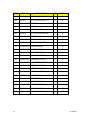
Label Formatting commands
These commands are used to format the printed label.
:nnnn
An
Cnnnn
cnn
Dwh
E
G
<STX>Sn
Hnn
M
m
n
Pn
Qnnnn
Rnnnn
rmnn..nn
smnn..nn
Tnn
z
+nn
>nn
-nn
^nn
<STX>T<string>
Sets cut amount (see cnn command)
Sets logical image printing mode
Sets left margin
Sets cut amount (valid with cutter is installed)
Sets width and height pixel size
Ends job and exits Label Formatting mode
Stores previous data to global register
Retrieves the global register contents
Sets heat value
Toggles the mirror mode
Sets unit of measure to metric
Sets unit of measure to inches
Sets print speed
Sets the quantity of labels to print
Sets vertical offset
Retrieves label data from printer buffer
stores label data to printer buffer
sets end-of-line code
Toggles slash zero to normal zero
Makes auto increment for numeric
Makes auto increment for alphanumeric
Makes auto decrement for numeric
Sets count amount
Prints date and time
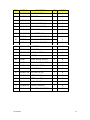
Image Editing Commands
Rthvoooyyyyxxxx[data string]
Rthvoooyyyyxxxx[data string]
RX11000yyyyxxxxLaaabbb
RX11000yyyyxxxxlaaabbb
RX11000yyyyxxxxBaaabbbtttsss
RX11000yyyyxxxxbaaabbbtttsss
1Y11000yyyyxxxxnn…nn
Text (t - font type)
Barcode (t- barcode type)
Line drawing
Line drawing
Box Drawing
Box Drawing
Graphics
Font Downloading command
<ESC>*c###D
<ESC>)s###W
<ESC>*c###E
<ESC>(s###W
58
Assigns soft font ID number
Downloads font descriptor
Sets character code
Downloads character descriptor and image
User Manual
Printer Programming Language B, PPLB
Specification
General fonts
5 fonts with different point sizes
Symbol sets
8 bits: code page 437, 850, 852, 860, 863 and 865.
(Code pages)
7 bits: USA, British, German, French, Danish, Italian,
Spanish, Swedish and Swiss.
Soft fonts
Downloadable soft fonts
Font expandability
1x1 to 24x24
Bar code types
Code 39(checksum), Code 93, Code 128/subset A, B, C,
Codabar, Interleave 2 of 5(checksum), Matrix 25, UPC A/E 2
and 5 add-on, EAN-8/13, Code 128UCC, UCC/EAN, Postnet,
German Postcode.
MaxiCode and PDF417 (2D symbologies).
Graphics
PCX and binary raster
Stand-alone operation without host
Fastkey
Notes: As the font board and flash modules use the same connector they cannot function
simultaneously.
PPLB Emulation Printer Control commands
See Programmer’s Manual for more details.
Note: Each command has to end in a Line Feed
Command
Ap1,p2,p3,p4,p5,p6,p7,"DATA"
Ap1,p2,p3,p4,p5,p6,p7,Cn
Ap1,p2,p3,p4,p5,p6,p7,Vn
Ap1,p2,p3,p4,p5,p6,p7,"DATA"Cn
Ap1,p2,p3,p4,p5,p6,p7,"DATA"Vn
Bp1,p2,p3,p4,p5,p6,p7,p8,"DATA"
Bp1,p2,p3,p4,p5,p6,p7,p8,Cn
Bp1,p2,p3,p4,p5,p6,p7,p8,Vn
Bp1,p2,p3,p4,p5,p6,p7,p8,"DATA"Cn
Bp1,p2,p3,p4,p5,p6,p7,p8"DATA"Vn
bp1,p2,p3,[specific parameters and data]
Cp1,p2,p3,p4,"MSG"
Dp1
EI
EK"ID"
ES"ID"..<font data>..
FE
FI
FK"ID"
FR"ID"
User Manual
Description
Prints Text
Prints Text Counter String (See Command C)
Prints Text Variable String (See Command V)
Prints Text Data with a Counter String (See Command C)
Prints Text Data with a Variable String (See Command V)
Prints Barcode Data
Prints Barcode Counter String (See Command C)
Prints Barcode Variable String (See Command V)
Prints Barcode Data with a Counter String (See Command C)
Prints Barcode Data with a Variable String (See Command V)
Prints 2D barcode
Defines Counter
Sets Darkness (heat setting)
Prints soft font list
Deletes soft font
Downloads soft font
Ends forms storage
Prints forms list
Deletes Stored Form
Retrives stored form
59
PPLB continued
Command
FS"ID"
GGp1,p2"ID"
GI
GK"ID"
GM"ID"p1
GWp1,p2,p3,p4,[raster image]
Ip1,p2,p3
JB
JF
LEp1,p2,p3,p4
LOp1,p2,p3,p4
LWp1,p2,p3,p5
N
Op1
Pp1,p2
PA
Qp1,p2
qp1
Rp1,p2
Sp1
TD[p1][p2][p3]
TT[p1][p2][p3]
TSp1,p2,p3,p4,p5,p6
U
UN
US
Vp1,p2,p3,p4,"MSG"
Xp1,p2,p3,p4,p5
Yp1,p2,p3,p4
Zp1
ZN
ZS
?
d0,1
d0,0
d5,0
d5,1
<ESC>KXnnnn
<ESC>KI;nnnn
<ESC>@0
60
Description
Stores form
Prints Graphic
Prints Graphics list
Deletes Stored Graphic
Stores Graphic
Prints Graphic immediately
Selects symbol set
Disables Back feed
Enables Back feed
Line Draw by Exclusive OR operation
Line Draw by OR operation
Draws white line
Clear Image Buffer
Select Options (DT, Cutter, Peeler)
Prints a Label
Prints Automatically
Sets Label and Gap length
Sets Label width
Set Origin location
Sets Print Speed
Defines date format
Defines Time format
Sets Real Time Clock
Prints Configuration
Disables Error Reporting
Enables Error Reporting
Defines Variable Data
Draws a box
Sets Serial port
Sets Print Direction
Disables Flash Memory
Enables Flash Memory
Downloads Variables and counters
Enables Euro character
Disables Euro character
Cutter with backfeed
cutter without backfeed
Label length of continuous labels
Cut and Peeler position
Clears flash memory
User Manual
Appendix E: Parts Lists and Mechanical Drawings
ITEM
PART NO.
DESCRIPTION
QTY
DETAIL
1
90.R4002.001 COVER MODULE
1
B
2
39.R4002.003 MIDCOVER
1
B
3
39.R4004.004 BOTTOM USB
1
D
4
90.R4001.005 CHASSIS MODULE
1
C
5
90.R4003.007 CHASSIS2 MODULE V7
1
D
6
42.R4004.003 PAPER-GUIDE (R) V3
1
D
7
42.R4003.003 PAPER-GUIDE (L) V3
1
D
8
32.R4004.001 GEAR 33T
3
D
9
35.R4004.003 SHAFT -FIBER
2
C,D
10
34.R4004.001 BUSH 4
4
D
11
42.R4010.001 BUSH-RIBBON
1
D
12
47.R4001.001 FIBER
4
D
13
40.R4005.001 PL ATE -FIBER
1
D
14
34.R4010.002 SPRING-FIBER2
1
D
15
42.R4011.001 BUSH-RIBBON
2
D
16
34.R4007.002 SPRTNG-RIBBON2
1
D
17
34.R4009.002 SPRTNG-FIBER1
1
D
18
33.R4010.001 BRACKET -SPRING
1
D
19
34.R4001.001 BUSH 1
4
D
20
47.A2008.011 RUBBER- USB (BLACK)
1
D
21
32.R4003.001 GEAR 66 T
1
D
22
33.R4009.001 BRACKET-FIBER
1
D
23
33.R4001.001 BRACKET -GEAR1
1
D
24
32.R4005.001 GEAR 46T
1
D
User Manual
61
ITEM
62
PART NO.
DESCRIPTION
QTY
DETAIL
25
59.R4003.001 CORE ADAPTER (RIBBON) 2
2
B
26
110478.1
1
D
27
32.21406.003 GEAR 42T
2
C,D
28
34.R4003.001 BUSH 2
1
D
29
34.21408.001 RUBBER FOOT
4
D
30
110478.4
1
D
31
32.R4002.001 GEAR 20X39T
1
D
32
32.21407.001 GEAR 66X 17T
1
C
33
33.R4016.003 SPRING-TOPCOVER
1
D
34
42.R4012.004 PAPER-SENSOR
1
D
35
32.R4007.001 PL ASTIC GEAR
1
D
36
33.R4002.002 BRACKET-GEAR2
1
C
37
33.R4004.003 BRACKET-SWITCH (L )
1
C
38
34.R4016.001 SPRING-BUTTON (L)
1
C
39
33.R4007.001 BRACKET -SHAFT (L )
1
C
40
34.R4012.001 SPRING-CHASSIS (L)
1
C
41
42.R4005.001 BUTTON-CHASSSI
2
C
42
35.R4001.001 SHAFT -HOLDER1
1
C
43
42.R4001.001 HOLDER-RIB
2
C
44
88.21131.409 WASHER (SW)
4
C
45
42.R4002.002 HOLDER-RIB2 V2
2
C
46
34.R4006.003 SPRING-RIBBON V3
2
C
47
35.R4003.001 SHAFT-HOLDER3
2
C
48
34.R4013.001 SPRING-CHASSIS (R)
1
C
KIT, PLATEN ROLLER
KIT, STEPPING MOTOR
User Manual
ITEM
PART NO.
DESCRIPTION
QTY
FIGURE
49
35.R4008.002 SHAFT2-CHASSIS
1
C
50
32.R4006.001 GEAR 48T
1
C
51
33.R4005.002 BRACKET-SWITCH (R )
1
C
52
34.R4017.001 SPRING-BUTTON (R)
1
C
53
33.R4008.001 BRACKET-SHAFT (R)
1
C
54
34.R4011.004 SPRING-TPH
2
C
55
33.R4003.007 BRACKET-TPH V7
1
C
110478.2
KIT, 200 DPI PRINTHEAD
1
56
110478.3
KIT, 300 DPI PRINTHEAD
1
C
57
110478.7
KIT, RIBBON SENSOR
1
D
58
33.R4011.003 COVER-TPH
1
C
59
35.R6001.001 SHAFT-TPH (L)
1
C
60
35.R4007.002 SHAFT1-CHASSIS
1
C
61
39.R4003.001 COVER-A
1
B
62
110948
GUIDE, MEDIA SUPPLY
2
B
63
110947
SPINDLE, MEDIA SUPPLY
1
B
64
34.R6001.001 SPRING-SHAFT (R)
1
C
65
35.R6002.001 SHAFT-TPH (R)
1
C
67
42.R4007.002 BUTTON-TOP (R)
1
B
68
42.R4006.002 BUTTON-TOP (L)
1
B
69
42.R4008.001 BUTTON (3-KEY)
1
B
70
55.R4001.011 PANEL BOARD
1
B
71
33.R4006.001 BRACKET-PEELER
1
D
72
33.R4014.002 BRACKET-CONNECTOR
1
D
User Manual
63
ITEM
64
PART NO.
DESCRIPTION
QTY
DETAIL
73
38.05008.001 SPACE-SUPPORT
1
D
74
55.R4005.002 CONNECT-PCB V2
1
D
75
110478.8
1
D
76
33.R4012.001 BRACKET -COVER1
1
D
77
32.R4001.001 GEAR 20X26T
1
D
78
42.R4014.001 RACK2-PAPER
2
D
79
33.R4015.001 SPRING-RACK2
1
D
80
33.R4013.001 BRACKET-COVER2
1
D
110478.5
KIT, MAIN PCB FM612
1
81
110478.6
KIT, MAIN PCB FM602/603
1
D
82
98.R4003.002 R400 SWITCHING POWER
1
D
83
34.R4015.001 SPRING-PEELER (R)
1
NOT SHOWN
84
34.R4014.001 SPRING-PEELER (L)
1
NOT SHOWN
85
42.R4019.001 PEELER-SWITCH (R)
1
NOT SHOWN
86
35.R4005.002 SHAFT-PEELER V2
1
NOT SHOWN
87
35.R4006.001 SHAFT-PEELER2
1
NOT SHOWN
88
42.R4017.001 PEELER-SWITCH (L1)
1
NOT SHOWN
89
42.R4018.001 PEELER-SWITCH (L2)
1
NOT SHOWN
90
39.R4007.002 PEELER-COVER
1
NOT SHOWN
91
55.R4004.001 PEELER-SENSOR
1
NOT SHOWN
92
33.20070.003 SPRING-RIBBON
4
NOT SHOWN
93
32.R6001.001 GEAR 22X33T
1
D
94
47.R4004.001 WASHER-SPRING
1
D
KIT, PAPER SENSOR
User Manual
ITEM
PART NO.
DESCRIPTION
QTY
DETAIL
95
47.R4005.001
WASHER2
2
C
96
33.R4020.001
BRACKET -SPRING2
1
D
97
42.R4023.001
BUSH-RIBBON
1
D
98
33.R4019.001
BRACKET-ADJ
1
C
99
35.R4001.002
SHAFT-HOLDER1 V2
1
C
100
88.12301.C06
WASHER-SPRING
2
C
A
86.1A324.4R0
SCREW M3X4 BLACK
6
C,D
B
86.VA824.4R0
SCREW T3X4 BLACK
13
C,D
C
86.VA324.6R0
SCREW T3X6 BLACK
27
C,D
D
86.AA324.6R0
SCREW I3X6 (T) BLACK
7
C,D
E
86.5A524.5R0
FLAT HEAD
4
C
F
86.VG524.6R0
SCREW T3X6 WASHER
2
D
G
86.1A324.6R0
SCREW M3X6 BLACK
1
D
H
88.81241.806
E -RING #5
5
C,D
I
88.81241.606
E -RING #3
14
C,D
J
88.81241.A08
E -RING #6
2
C
K
88.81241.406
E -RING #4
2
C
L
86.VA324.8R0
SCREW T3X8
6
D
M
86.VA424.370
SCREW T3X37
2
NOT SHOWN
N
86.1A522.2R0
SCREW M2X2 NI
2
NOT SHOWN
O
86.AA522.6R0
SCREW T2X6
4
NOT SHOWN
P
86.1A524.8R0
SCREW M3X8 NI
1
C
User Manual
65
Detail A
66
User Manual
Detail B
User Manual
67
Detail C
User Manual
68
Detail D
69
User Manual
AMT Datasouth Corp.
Corporate Headquarters
4765 Calle Quetzal
Camarillo, CA 93012
(805) 388-5799 PH
(805) 484-5282 FX
Charlotte Operation
4216 Stuart Andrew Blvd.
Charlotte, NC 28217
(704) 523-8500 PH
(704) 525 6104 FX
www.amtdatasouth.com
AMT Datasouth International
Unit B, Pinnacle 15
Gowerton Rd, Brackmills
Northampton, NN4 7BW
England
+44 1604 763394 PH
+44 1604 760661 FX