1
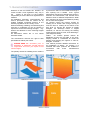
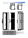
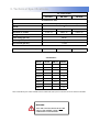
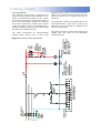
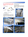
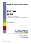
Instruction Manual.
AMBIENT AIR CURTAIN
AB 150A, AB 175A & AB 225A
INDEX
Section
General Information ----------------------------------------------------------- 1
Dimensions ----------------------------------------------------------------------- 2
Technical Specifications ------------------------------------------------------ 3
Installation Details -------------------------------------------------------------- 4
Wiring Details ------------------------------------------------------------------- 5
Servicing -------------------------------------------------------------------------- 6
Parts Replacement ------------------------------------------------------------ 7
Spare Parts ---------------------------------------------------------------------- 8
Fault Finding --------------------------------------------------------------------- 9
User Instructions -------------------------------------------------------------- 10
WARNINGS
1 This appliance must only be installed by a competent person in accordance with
the requirements of the Codes of Practice or the rules in force.
2 All external wiring MUST comply with the current IEE wiring regulations.
3 Warning this appliance must be earthed.
1. General Information.
Welcome to the new Airbloc AB ambient air
curtain models. Local regulations may vary in
the
country of use and it is the installers
responsibility to ensure that such regulations are
satisfied.
All installation, assembly, commissioning and
service procedures must be carried out by
suitably qualified competent persons to the
statutory regulations in the country of use.
When assembling, installing, commissioning and
servicing is undertaken on the air curtains is
required to ensure that working at height
regulations are adhered to at the mounting heights
specified.
All dimensions shown are in mm unless
otherwise stated.
The manufacturer reserves the right to alter
specifications without prior notice.
PLEASE READ this document prior to
installation to familiarise yourself with the
components and tools you require at the
various stages.
to prevent the influx of cold outside air through a
door opening into a heated
area. Typical
applications include large despatch bay doors in
factories and warehouses, and internal doors
between areas of different temperatures. Wider
door openings can be accommodated by bolting
two or more units together.
Air curtains control the internal climate by
emitting an air stream with enough velocity to
meet the floor so creating an air barrier in the
door area. To prevent the ingress of outside
draughts, the discharge louvre is angled
outwards, so that the air leaving the building
meets the wind trying to enter, thus deflecting it.
(See diagrams below).
Airbloc
air curtains provide uniform air
distribution across the full width of the door,
keeping heated or conditioned air inside the
building and stopping the ingress of cold air,
draughts, and dust.
This manual provides detailed information on
the installation of Airbloc air curtains. It is
essential that these products are installed in
accordance
with
these
manufacturers
instructions.
The primary reason for installing an air curtain is
Without air curtain
With air curtain
Pattern of airflow
2. Dimensions.
Model
A
mm
B
mm
C
mm
D
mm
E
mm
F
mm
G
mm
H
mm
Weight
(kg)
AB 150A
1500
523
457
507
260
86
1345
201
80
AB 175A
1750
523
457
507
260
86
1695
201
90
AB 225A
2250
523
457
507
260
86
2195
201
115
H
*R/H VIEW LPHW/STEAM*
Diagram 1: Dimensions
*Typical projection for LPHW/steam
housing (dimension H) LPHW/steam
coils available to order.
See contact details on rear cover of this
document.
3. Technical Specifications.
Air curtain model
AB 150A
AB 175A
AB 225A
Air distribution fans
Type
Centrifugal (with integral thermal trip)
Speeds
3
No. of fans
2
3
3
Maximum air volume
4
3
4712m /hr
7068m /hr
Voltage
9425m3/hr
230V 1PH 50Hz
Power rating (per fan)
550 W
Current (per fan)
4.5A (FLC)
Start current (per fan)
11.25A
Power
Total electrical power consumption
1.100kW
1.650kW
2.200kW
Constitution*
Model
AB150
AB150=
x1
AB300=
x2
AB175
AB350=
x2
AB400=
x1
AB450=
AB225
x1
x2
AB525=
x3
AB575=
x2
x1
AB625=
x1
x2
AB675=
x3
* table shows full range of models available and the modules that make up their construction. No other variants are available.
WARNING:
THIS AIR CURTAIN SHOULD NOT BE
INSTALLED WHERE THERE IS A
CORROSIVE ATMOSPHERE.
4. Installation Details.
Health and Safety
Due account should be taken of any obligations
arising from the Health and Safety at Work Act
1974 or relevant codes of practice. In addition
the installation must be carried out in
accordance with the current IEE wiring
regulations and any other relevant British Standards and Codes of Practice by a qualified installer. Isolate all electrical supplies to the heater &
control panel before proceeding.
For your own safety we recommend the use of
personal protective equipment when handling
this air curtain.
Airbloc air curtains are supplied with mounting
brackets pre-fitted, and can be mounted either
as single units, or in multiples, which can be
bolted together to suit various door widths.
The minimum mounting height is 3 metres (See
diagram 2 below).
4.1
Each single air curtain should be supported by
cantilever brackets (not supplied) then fixed
back to the building structure by bolting directly
using suitable support brackets, or by
suspending from above using suitable
steelwork. (See diagram 3, page 6).
4.3 Mounting.
Diagram 2.
Gap to be kept to a
minimum
4.2
Multiple air curtains should be bolted together
using 3 off M10 set pins, nuts and washers fitted
through the holes provided in the mounting
brackets, then suitable support channels (not
supplied) must be fixed on top of the factory
fitted brackets along the full length of the
assembled air curtains to spread the load.
The assembly can now be fixed back to the
building structure by bolting directly using
suitable support brackets, or suspending from
above using steelwork. (See diagram 4 page 6).
If required, the support channel may be
extended slightly past the ends of the air
curtains to aid fixing.
Note: Where multiple air curtains are fitted
above up and over doors or where
central support is inappropriate, the support
channel should be replaced with channels of a
greater cross section to prevent the assembly
from bending.
It may be necessary to adjust the position of the
air outlet louvres to provide the correct airflow
across the door opening. This can be done by
first loosening the four locking pins located two
at each end of the louvres (arrowed, Fig. A),
then loosening the intermediate locking Allen
pins (arrowed, Fig. B). The louvres can now be
moved to the desired position and the locking
pins re-tightened.
Note: The AB 225 model has two pairs of
intermediate locking Allen pins, whereas the
AB 175 model only has one pair.
Fig. A
Bottom of air
curtain to be
level with top of
door opening
Locking pins
Fig. B
3m minimum
Locking Allen pins
4. Installation Details cont.
Diagram 3: Mounting method (single air curtain)
FRONT VIEW (SINGLE AIR CURTAIN)
Cantilever brackets
(not supplied)
Factory fitted
mounting brackets
Diagram 4: Support channel (multiple air curtains)
PLAN VIEW (TWIN AIR CURTAINS)
Support points
Air curtain 1
Typical support channels
WARNING:
THIS AIR CURTAIN SHOULD NOT BE
INSTALLED WHERE THERE IS A
CORROSIVE ATMOSPHERE.
Air curtain 2
Factory fitted brackets
5. Wiring Details.
The panel incorporates an auto/off/manual
selector switch, which, when in 'auto' mode
operates the air curtain as the door opens and
closes. The 'manual' position overrides the door
interlock, and the 'off ' position turns the air
curtain off.
The panel also contains a removable link on the
main terminal rail to allow the air curtain to be
switched on and off remotely via a BMS control
relay or remote switch.
The panel may also be fitted with optional low
voltage (24V AC) relays for fire alarm/door
contact interlocks.
3
1
1
N
FAN MOTORS
4.5A FLC
1
E
N
L3
L2
L1
415 VOLT
3 PHASE
50 Hz
4 WIRE
SUPPLY
DOOR LOCKED
ISOLATOR
AIR CURTAIN MODULE
UPTO 4 FAN MOTORS
3
3
1 2 2 2 2 3
FAN TERMINAL BOX
MEDIUM
SPEED
LOW SPEED
CA
MCB1
25A
HIGH SPEED
MCB4
4A
NOTE:
FIELD WIRE MOTOR
SPEEDS AS FOLLOWS:
1=LOW SPEED
2=MEDIUM SPEED
3=HIGH SPEED
PANEL
LIVE
CA
BMS
INTERLOCK
LINK IF NOT
REQUIRED
AUTO
OFF
MAN
DOOR
INTERLOCK
MAKES AS
DOOR
OPENS
Diagram 8: Generic control panel wiring
FAN
CONTACTOR
MOTOR LEAD COLOURS:
LOW SPEED
RED
BLUE MEDIUM SPEED
BLACK HIGH SPEED
WHITE NEUTRAL
5.1 Control panel.
The electrical control panel incorporates the
facility to interlock with the door opening mechanism and automatically switch the air curtain
on and off as the door is opened and closed. A
pair of volt free auxiliary contacts are required
on the door open/close contactor which closes
as the door opens. If this is not available then a
suitably positioned limit switch and striker plate
will need to be fitted to the door.
6. Servicing.
These appliances should be serviced annually by a competent person to ensure safe and
efficient operation. In exceptionally dusty or polluted conditions more frequent
servicing may be required. The manufacturer offers a maintenance service. Details available
on request. Isolate electricity supplies before commencing any work.
6.1 Tools required.
The following tools and equipment are
recommended to complete the tasks laid out in
this manual.
Suitable alternative tools may be used.
10mm spanner
Cross point
screwdriver
Small flat head
screwdriver
13mm spanner
Soft
brush
Allen key set
6.2 Air outlet louvres.
The air outlet louvres should be cleaned with a
soft brush. Check that the louvres are set to the
required angle. (See Figs. A/B on page 5 for
setting procedure).
6.3 Air distribution fans.
The air distribution fans can be accessed by
opening the fan access lid as described in
section 7.1.
Clean off any dust or deposits with a soft brush
paying particular attention to the impeller. Check
that the impeller spins freely, and that there is
no play in the fan bearings.
The fan(s) can be removed, if necessary, as
described in section 7.1.
6.4 Electrical.
Isolate
electricity
supplies
commencing any work.
before
Check condition and tightness of all terminations
in control panel.
Remove the fan terminal box cover located on
top of the air curtain (Fig.1), and repeat above
procedure for the fan terminations.
Adjustable
spanner
Check that the plug/socket connection to each
fan (inside the unit) is tight and that the cable is
in good condition. Switch control panel on and
check air curtain operation in each selector
switch position (auto/off/man, low/medium/high
speed).
Fig.1
7. Parts Replacement.
All servicing/maintenance work on this air
curtain should be carried out by suitably
qualified person. Before commencing any work
please ensure that the electricity supplies are
turned off.
7.0 Tools required.
The lid can now be hinged down to access the
fans as shown in Fig.4.
7.1.1 Fan closure plate
Before individual fans can be removed it will be
necessary to remove the fan closure plate.
Remove the retaining screws around the
perimeter of the plate. (See Figs.5/6) The plate
can now be removed.
Fig.4
Allen key set
10mm spanner
Cross point
screwdriver
Adjustable
spanner
13mm spanner
7.1 Air distribution fans.
The air distribution fans can be accessed by
removing the three screws along the bottom
edge of the air inlet grille (Fig.2), and the
retaining screws securing the hinged lid on the
underside of the air curtain next to the louvres
( Fig.3).
Fig.2
Fig.5
Fan closure plate
Fan outlet
Fig.3
Fig.6
Fan outlet
Fan closure plate
7. Parts Replacement cont.
7.1.2 Fan removal
Identify the feed cable for the fan requiring
removal and disconnect it from its cable mounted plug/socket. (See Fig.7 )
The four bolts securing the fan can now be
removed as shown in Fig.8, and the fan
removed from the air curtain downwards.
Fig.8
CAUTION: these fan units are heavy.
Fig.7
Fig.9 shows single air distribution fan in
isolation for clarity.
Fig.9
8. Spare Parts.
The air distribution fans and 5 pin plug/socket
are available as a spare part as detailed below.
Item
Description
Part No.
3 speed air
distribution fan
unit
AB-FAN
Note: Any spare parts or components used
that are not approved by AmbiRad could
invalidate the approval of the appliance and
also the warranty.
Item
Description
Part No.
Air distribution
fan 5 pin plug/
socket
Plug: 3127
Socket: 3126
9. Fault Finding.
Air distribution fans
Power on to control
panel?
NO
Check:
1. Power supply.
YES
All air
distribution
fans off?
YES
Check:
1. Control panel man/off/auto
switch position.
2. Fan circuit breaker(s)
3. Fan contactor and
associated wiring.
NO
Single fan
unit off?
If the fan(s) still fail to
operate normally,
please contact
the AmbiRad
service department.
YES
Check:
1. Motor thermal trip (may run
when cool), test motor.
2. Motor wiring.
3. Motor plug/socket.
10. User Instructions.
10.1 Important information
This appliance must only be installed by a
competent person in accordance with the
requirements of the codes of practice and the
rules in force in the country of use.
10.1.1 The appliance must be earthed.
10.1.2 Never rest anything, especially ladders,
against the air curtain.
10.2 To start the AB air curtain (manual)
10.2.1 Rotate the control panel auto/off/manual
selector switch is in the manual position.
10.2.2 Switch on electrical supply to the control
panel. The panel live lamp will illuminate and the
air distribution fans will start.
10.3 To start the AB air curtain (auto)
10.3.1 Rotate the control panel auto/off/manual
selector switch is in the auto position.
10.3.2 Switch on electrical supply to the control
panel. The panel live lamp will illuminate and the
air distribution fans will only start if the door is in
the raised position.
10.4 To start the AB air curtain (BMS control)
10.4.1 Rotate the control panel auto/off/manual
selector switch is in the auto or manual position.
10.4.2 Switch on electrical supply to the
control panel. The panel live lamp will illuminate
and the air distribution fans will now only
operate when the BMS relay or remote switch is
closed.
10.5 To switch off the AB air curtain
10.5.1 Rotate the auto/off/manual control panel
selector switch to the 'off' position. The air
distribution fans will stop. Switch off the
electrical supply to the control panel. The panel
live lamp will extinguish.
10.6 Servicing
To ensure continued efficient and safe operation
it is recommended that the air curtain is serviced
regularly by a competent person, once a year in
normal working conditions, but in exceptionally
dusty or polluted conditions more frequent
servicing may be required.
The manufacturer, (AmbiRad address given
below), offers a maintenance service, details of
which are available on request.
For sales related queries please contact the
Nordair Niche address given below.
WARNING:
Document reference number GB/AIR/039/0213
THIS AIR CURTAIN SHOULD NOT BE
INSTALLED WHERE THERE IS A
CORROSIVE ATMOSPHERE.
Nordair Niche (Northern Office)
6-14 Bean Leach Road,
Hazel Grove, Stockport,
Cheshire. SK7 4LD
United Kingdom
Telephone
0161 482 7900
Facsimile
0161 482 7901
Email [email protected]
Website www.nordairniche.co.uk
AmbiRad Limited Fens Pool Avenue
Brierley Hill West Midlands DY5 1QA
United Kingdom.
Telephone
01384 489700
Facsimile
01384 489707
Email [email protected]
Website www.airbloc.co.uk
Technical Support www.s-i-d.co.uk