1
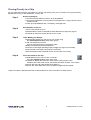
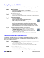
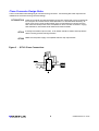
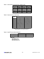
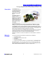
QTM300CA USER'S GUIDE
Cloning Adapter for the QT3xx family of QProx™ ICs
Description
The QTM300CA is a
cloning adapter designed
to interface between any
QT3xx 8-pin sensor IC
(QT300, QT310, QT320)
and a PC or other host
device.
This adapter permits the
designer to upload
settings from a PC into the
target chip or to read the
settings inside a chip. The
supplied cable allows the
board to plug directly into
both the E3A and E3B
eval boards.
For production use, the
target PCB can have a similar connector which allows the QTM300CA to upload
settings on a mass basis. The cloning process takes under 1 second to complete.
The QTM300CA’s eeprom memory permits the board to be used as a stand-alone
cloning adapter once it is programmed from a PC with the desired setups. An onboard
socket also allows the user to program QT3xx parts individually. The QTM300CA can
also be used to read back and verify the settings in QT3xx parts.
For the QT300 continuous IC, this adapter also provides the additional functionality of
interfacing to that device’s SPI port to download signal data, which can then be
observed directly on the PC in real time using QT3View software.
QT3View PC software is included, and updates can be downloaded from Quantum’s
web site.
Materials
Provided
You should find the following materials included with your QTM300CA:
1x QTM300CA board
1x RS232 DB-9 serial extension cable
1x 9V battery
1x QT3View user guide
1x CD Rom with QT3View software (or, download latest from www.qprox.com)
You will also need: A PC running any recent version of Windows (98, 98SE, NT4,
2000, XP) upwards, with a free serial port (Com 1 or Com 2), and if desired a bench
power supply to replace the battery (9 - 15V DC) for long term use.
1
QTM300CA/R1.01 07/02
Overview
The QTM300CA can operate in two basic modes:
- PC-driven mode
- Stand-alone mode
In PC-driven mode, you can a. Load Setup information into it for all three part types for use in stand-alone mode,
from a PC running QT3View.
b. Communicate directly from the PC to the QT3xx part without disturbing the
contents of the QTM300CA.
c. Read back the Setups of any QT3xx device to your PC.
d. View actual signal data on-screen in real time (QT300 only).
e. Store many Setups files to disk, and program your devices from them.
In Stand-alone mode, you can a. Auto-select which device (QT300 or other) will be cloned.
b. Load Setups information stored in the QTM300CA to a QT3xx device, for example
in a production setting.
Which mode? PC mode is entered automatically when a PC running QT3View software is connected
to the QTM300CA. If this is not the case, the board defaults to Stand-alone mode.
Use PC mode for development, and Stand-alone mode for production.
Quick Start
To begin using the board right away
1. Connect the QTM300CA to a PC using the serial cable (included). Make sure the
serial port is not being used by any other application or driver.
2. Connect the QTM300CA to the target board’s 7-pin cloning header; the stripe of
the cable connects to the pin marked with a white square.
3. Run QT3View on the PC.
4. Power up the target board and the QTM300CA.
QT3View will communicate with the QTM300CA and determine the specific QT3xx
variant installed on the target board. The appropriate tab for the detected part will
appear on top.
To show the current Setups in the chip, click the [ Sensor | Download from Chip ]
button (see page 5); the Setups on the tab will be updated with what is in the chip.
It is now possible to change the Setups from the PC using the selector boxes. The new
Setups become effective as soon as you make the change and will operate the next
time you power up the chip in its normal operating mode.
When you are done making changes, unplug the cloning cable and reset the QT3xx
chip to cause it to recalibrate and run properly.
Note: The cloning adapter is tolerant of power sequencing; it does not matter whether
the cloning adapter or target is powered up or switched off first.
2
QTM300CA/R1.01 07/02
Figure 1 - Board Layout
Board Details
Power Switch Selects between the onboard battery (right) or an external power source (left).
Power For external power, between +8 to +20 Volts DC. Power should be free from switching
Connector noise and short-term fluctuations for best performance. A 9V battery is fine for short
term use, but make sure the battery does not drain to below 8V or erroneous operation
can occur.
RS232 Provides communications between the QTM300CA and the PC. It allows the user to
Connector upload or download setups from the cloning adapter to the target QT3xx. The cable to
the PC should be an ‘extension’ type (wired 1:1), included.
Cloning Connects to the target board and can be connected whether or not the target is
(Ribbon) Cable powered. The cable has a strip on one side; care should be taken not to reverse this
cable. The stripe connects to pin 1 (white square) of the E3A or E3B board.
IC Programming The QTM300CA can be used to program QT3xx chips onboard. The board can accomSocket modate either a ZIF socket or a SMT socket (when used with appropriate adapters, not
included - see ZIF Info, Page 10.
In Stand-alone mode, once the chip to be programmed is inserted, the QTM300CA will
detect the chip part number and display it on the ‘DEV0 and DEV1’ LEDs (see below).
Program If a QT3xx chip has been auto-detected, this button will clone Setups data from the
Button QTM300CA to the chip. The ‘PROG’ LED (see below) indicates the programming result.
The QTM300CA can store three sources of data, one for each part type. The correct
source will be used to program the detected part.
3
QTM300CA/R1.01 07/02
Status LEDs
PC Indicates if QT3View software is communicating with the QTM300CA.
This LED will turn off five seconds after communications have stopped.
DEV0, DEV1 Displays the chip type connected via the ribbon cable or in the onboard socket:
DEV1
On
On
DEV0
On
On
Device
None
QT300
QT310
QT320
PROG Indicates the programming status of the target chip in Stand-alone mode.
The PROG LED will light during the cloning process in Stand-alone mode.
Afterwards the LED will flash on/off 3 times to indicate completion:
Fast flashing: (0.1s between flashes) the clone process was a success.
Slow flashing: (1s between flashes) the clone process failed.
If the QTM300CA is not in communication with QT3View software, the PROG LED will
flash on and off.
4
QTM300CA/R1.01 07/02
Figure 2 - QT3View Screen
QT3View Operation
Part Selector Allows you to view and communicate with the right part. Any serial data transfer will
Tabs involve only the active tab. The software will auto-recognize the type of chip connected
to the QTM300CA and choose the right tab for you.
If no chip is installed, the tab can be manually selected to allow data transfers with the
QTM300CA’s onboard e2prom.
File | Open Restores a config file saved by (File | Save). All three part selector configurations (tabs)
will be restored by this action.
File | Save Saves all three part selector configurations to disk in a single file, to a file name of your
choice.
Sensor | CommPort Selects the desired PC serial port. Com1 is selected by default when the software is
first started, if it is available.
Sensor | Upload
to Adapter
Sends the Setups of the open tab to the QTM300CA’s onboard e2prom for use
in later cloning. Repeat this step with each selector tab opened in turn, to
upload Setups for multiple part types.
Sensor | Download
from Adapter
Reads the Setups from the e2prom of the QTM300CA into the currently open
selector tab. Only the data for the open tab is read. Repeat this step with each
tab open in turn to read in all the configurations stored in the QTM300CA.
Sensor | Upload
to Chip
Sends the Setups from the currently open selector tab directly to the e2prom
of a QT3xx chip. Data stored in the QTM300CA is not affected by this operation. The open tab must coincide with the connected chip type.
Sensor | Download
from Chip
Reads the Setups directly from the e2prom of a connected QT3xx chip into the
corresponding selector tab. Data stored in the QTM300CA is not affected by
this operation.
5
QTM300CA/R1.01 07/02
Setup and These show and modify the available Setups for the chosen chip.
Guideline Boxes
Timing related values have no meaningful unit of measure unless interpreted together
with the device supply voltage and Sleep Cycles. To aid in understanding the effects of
these Setups, ‘Guideline’ boxes are used next to timing related Setups to give an
estimate of the result in seconds.
Guideline boxes cannot be modified, they only exist to inform you of the effects of the
timing Setups. Guideline numbers will change if Sleep Cycles, Burst Length, or Voltage
are changed, because QT3xx device timings vary with these things.
The QTM300CA and QT3View cannot directly measure the effects of Setup changes or
supply voltage changes. The numbers presented are reasonable estimates only.
Hardware Allows you to dial in the expected chip supply voltage and the burst length (total of both
Parameter channels together in the case of the QT320) in order to allow Guideline boxes to show
Entry reasonably accurate timing values. The QTM300CA cannot measure these parameters.
To measure the burst length, use an oscilloscope with a 750K series resistor on the
probe tip to limit loading, and measure from the start of the first pulse to the end of the
last. Add together the burst lengths of both channels when entering the number for the
QT320.
Status Bar The status bar at the bottom shows the serial port and connection status.
Display Possibilities are:
Serial Port Status:
- Off Line
- COM1: 57600 N 8 1
- COM2: 57600 N 8 1
Connection Status:
- Status: Clone connected
- Status: Clone & QT300 connected
- Status: Clone & QT310 connected
- Status: Clone & QT320 connected
- Status: No Clone
6
QTM300CA/R1.01 07/02
Cloning Directly to a Chip
You can read and clone back information to a QT3xx chip directly from your PC without involving the onboard
stand-alone memory of the QTM300CA. Here’s how....
Step 1
Hook everything up:
Connect the serial cable from the PC to the QTM300CA.
Connect the QTM300CA’s cloning cable to the target PCB, or plug a QT3xx into the
onboard socket.
Power up the QTM300CA and, if necessary, the target PCB.
Step 2
Start QT3View on the PC:
The PC LED should come on.
DEV0 and DEV1 LEDs will indicate the auto-detected chip type (see page 4).
QT3View will select the proper part tab on the screen.
Step 3
Load / Modify your Setups:
Download the Setups from the chip to your screen using
the ‘Download from Chip’ button (see right) or,
Load in a Setups file from disk
(this will overwrite all three configuration tabs).
Modify the Setups parameters as desired.
Enter the correct target operating supply voltage (see page 6) if necessary.
Enter the total burst length (see page 6) if necessary.
Save the Setups to disk if desired (saves all three tabs into one file).
Step 4
Clone the Setups to the chip:
Upload Setups to the chip from the current tab
using the ‘Upload to Chip’ button (see right).
QT3View will display the success or failure of the clone process in the
indicators at the left of the screen (the PROG LED does not work in this mode).
Remove the chip and install another and repeat, or,
Remove the clone cable and connect to another target PCB and repeat.
Refer to the device data sheet and the QT3View help file for more information on Setup issues.
7
QTM300CA/R1.01 07/02
Storing Setups into the QTM300CA
You can save Setup information from the PC to the onboard eeprom of the QTM300CA for use in cloning of
parts on a stand-alone basis. You can also read back these Setups to your PC at any time to verify them. The
QTM300CA can independently store three Setup configurations, one for each part type. Here’s how.....
Step 1
Hook everything up:
Connect the serial cable from the PC to the QTM300CA.
Power up the QTM300CA.
A target chip or board can be connected but in this process it will not be affected.
Step 2
Start QT3View on the PC:
The PC LED should come on.
DEV0 and DEV1 LEDs will flash to indicate ‘no part found’ if no part is connected.
Step 3
Load / Modify the Setups:
The PC LED should come on.
Select the device tab in QT3View that you wish to work on.
Load in a Setup file from disk if desired, or,
Load in the Setups stored in the QTM300CA using the ‘Download from
Adapter' button into the current tab. Note, the other tabs will not be
affected.
Enter the target operating voltage and burst length (see page 6) if desired.
Change the Setups in the current part tab using the dialog boxes, if desired.
Select a different device tab if you wish to work on another part type, and repeat.
Step 4
Transfer the data to the QTM300CA’s internal eeprom:
Select the device tab which you want to upload to the QTM300CA.
Upload the current tab Setup contents to the QTM300CA using the
‘Upload to Adapter' button.
QT3View will display the success or failure of the copy process in the
indicators at the left of the screen.
Repeat with other tabs open if desired to copy over other part type Setups
Cloning Setups from the QTM300CA to a Chip
You can clone Setup information from the QTM300CA to a chip either on a target PCB or inserted into the
onboard socket, without the need for a PC. The QTM300CA stores the Setup information in its onboard
eeprom for use in cloning. The three part types, QT300, QT310, and QT320 each have their own ‘page’ of
Setups in the QTM300CA. Here’s how.....
Step 1
Hook everything up:
Connect the QTM300CA’s cloning cable to the target PCB, or plug a QT3xx chip
into the onboard socket.
Power up the QTM300CA and, if necessary, the target PCB.
The DEV LEDs should indicate the correct part (auto-detected); see page 4.
Step 2
Clone the Setups to the Chip:
Push the PROG button on the board.
The PROG LED will light to indicate programming status.
The PROG LED will flash to indicate the programming result; see page 4.
8
QTM300CA/R1.01 07/02
Clone Connector Design Rules
Care must be taken when designing an onboard cloning connector. The following are a few requirements
needed for a successful cloning connector design.
QT320/QT310 Place the connector as close as possible to the chip. Placing the cloning connector far
from the part will increase sensor load capacitance Cx and decrease sensitivity, as
some of the cloning lines are also sense lines. Long distances on cloning lines can
also make the clone process more susceptible to communication errors from ringing
and interference, and create an RF antenna for external fields.
QT310 If the Synchronization input is used, a 1K resistor should be used to avoid problems
with the cloning process; see figure below.
QT300 Make sure the power supply is compatible with the chip requirements.
SDI
SCK
SDO
GND
Figure 3 - QT310 Clone Connections
Vdd
8
Vcc
1
CAL /LATCH
CAL
LATCH
2
SOUT
SIN
S1a
/SCK
Sout
6
Out 7
/SDI
3
SENSOR 1
5
Sin
/SDO
OUT
CS
S1b
GND
4
9
QTM300CA/R1.01 07/02
Table 1 - Clone Cable Functional Pinout - Usage by Part
Pin
QT300
QT310
QT320
1
2
3
4
5
6
7
GND
DRDY
SDO
N/C
SDI
Vcc
SCK
GND
N/C
SDI
N/C
SDO
Vcc
SCK
GND
N/C
SDI
N/C
SDO
Vcc
SCK
Table 2 - Clone Connector Cable Pinout
Pin
1
2
3
4
5
6
7
8
9
10
Description
Board Connector
End Connector
Vcc
GND
GND
DRDY
DRDY
SDI (1) / SDO (2)
NC
NC
NC
SDO (1) / SDI (2)
SDI (1) / SDO (2)
Vcc
SDO (1) / SDI (2)
SCK
Vcc
SCK
NC
-
Note 1: Applies only to QT310 & QT320 (see Table 1).
Note 2: Applies only to QT300 (see Table 1).
Table 3 - Chip ZIF Socket Order Information
Digi-key
Farnell
Logical Systems
ZIF DIP Socket
3M1602-ND
103-907
-
ZIF SMT Socket
309-1048-ND
PA8SO1-2006-6
Web sites:
www.digikey.com
www.farnell.co.uk
www.logicalsys.com
10
QTM300CA/R1.01 07/02
Quantum Research Group Ltd.
1 Mitchell Point, Ensign Way
Hamble, Southampton SO31 4RF
Great Britain
Quantum Research Group Ltd.
651 Holiday Drive Suite 300
Pittsburgh, PA 15220
USA
Tel: +44 (0)23 80453934
Fax: +44 (0)23 80453939
[email protected]
www.qprox.com
Tel: +1 (412)391-7367
Fax: +1 (412)291-1015
[email protected]
www.qprox.com
Patents Pending Worldwide
QTM300CA/R1.01 07/02