1
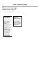
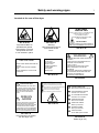
Installation manual T4300S Selecta Control 487 05 45 80/US 09.26 Safety and warning signs WARNING: ALL OPERATING AND MAINTENANCE PROCEDURES SHOWN ON THE NEXT PAGE OF THIS MANUAL MUST BE FOLLOWED DAILY FOR PROPER OPERATION OF YOUR ELECTROLUX MACHINE. KEEP THIS MANUAL IN A SECURE PLACE FOR FUTURE REFERENCE. Warning: For your safety the information in this manual must be followed to minimize the risk of fire or explosion or to prevent property damage, personnel injury or death. 3 Safety and warning signs 4 NOTICE TO: OWNERS, OPERATORS AND DEALERS. IMPROPER INSTALLATION AND INADEQUATE MAINTENANCE, POOR HOUSEKEEPING AND WILLFUL NEGLECT OR BYPASSING OF SAFETY DEVICES MAY RESULT IN SERIOUS ACCIDENTS OR INJURY. TO ASSURE THE SAFETY OF CUSTOMERS AND/OR OPERATORS OF YOUR MACHINE, THE FOLLOWING MAINTENANCE CHECKS MUST BE PERFORMED ON A DAILY BASIS. 1. Prior to operation of the machine, check to make certain that all operating instructions and warning signs are affixed to the machine and legible. (See the following page of this manual for description and location of the signs.) Missing or illegible signs and labels must be replaced immediately. Be sure you have spare signs and labels available at all times. These can be obtained from your dealer. 2. Check the door safely switch, as follows: (a) OPEN THE DOOR of the machine and attempt to start in the normal manner: THE MACHINE(S) SHOULD NOT START! (b) CLOSE THE DOOR to start machine operation and, while it is operating, open the door: THE MACHINE(S) SHOULD STOP. If the machine can operate with the door open, it must be placed out of order until the necessary repairs are made. 3. DO NOT UNDER ANY CIRCUMSTANCES ATTEMPT TO BYPASS OR REWIRE ANY OF THE MACHINE`S SAFETY DEVICES AS THIS CAN RESULT IN SERIOUS ACCIDENTS, AND WILL VOID YOUR WARRANTY. 4. Be sure to keep the machine(s) in proper working order: Follow all maintenance and safety procedures. Further information regarding machine safety, service and parts can be obtained from your dealer. All requests for assistance must include the model, serial number and electrical characteristics as they appear on the machine identification plate. 5. WARNING: DO NOT OPERATE MACHINE(S) WITH SAFETY DEVICES BYPASSED, REWIRED OR INOPERATIVE! 6. A wiring diagram for your machine is located behind the front panel. Safety and warning signs 5 WARNING– Risk of fire Clothes dryer installation must be performed by a qualified installer. Install the clothes dryer according to the manufacturer's instructions and local codes. Do not install a clothes dryer with flexible plastic venting materials. If flexible metal (foil type) duct is installed, use duct that has been investigated and found acceptable for use with clothes dryers. Flexible venting materials are known to collapse, be easily crushed, and trap lint. These conditions will obstruct clothes dryer airflow and increase the risk of fire. To reduce the risk of severe injury or death follow all installation instructions. Save these instructions. Safety and warning signs 6 Safety and warnings signs Located at the front of the dryer Replace if missing or illegible. One or more of these signs must be affixed on each machine. WARNING! Dry water-washed fabrics ONLY. To avoid hazard, do not use heat when drying articles containing foam rubber or similarly textured rubber like materials. DO NOT dry items containing gasoline, oil, kerosene, paint, wax, grease, or other combustible materials. Remove items immediately after drying. DO NOT let children play in or near dryer. DO NOT use dryer in the presence of dry cleaning solvents DO NOT store or use flammable liquids or aerosols near dryer. 487 22 26 50 CAUTION! A clothes dryer produces combustible lint and the area around the clothes dryer should be kept free of lint. Lint screen must be cleaned in accordance with the manufacturer's recommended frequency guidelines. 487 22 26 51 Safety and warning signs 7 Located at the rear of the dryer CAUTION Risk of Fire A clothes dryer produces combustible lint and should be exhausted outdoors. See installation manual. THIS DRYER MUST BE EXHAUSTED TO THE OUTDOORS. 487 18 97 33 Dryer MUST NOT be operated with guards, outer panels, or service door/panels removed or not secured in place. 487 18 97 34 “Warning” High temperatures which could cause severe burns. INSTRUCTIONS INSPECT EXHAUST DUCTING EVERY 6 MONTHS AND REMOVE LINT BUILDUP. 487 18 97 42 WARNING IMPORTANT DO NOT JUMP WIRES AROUND AIR SWITCH. DO NOT TAPE SWITCH DAMPER SHUT. DO NOT RESTRICT FLOW OF AIR TO SWITCH. 487 18 97 43 Får ej övertäckas Do not cover Nicht überdecken Ne pas couvrir Må ikke overdækkes Ei saa peittää Non coprire Nezakrývejte 487 19 69 74 PLUMBERS BEWARE WHEN PRESSURE TESTING!!! DRYER MUST NOT BE SUBJECTED TO PRESSURE THAT EXCEEDS 1/2 psig (3.5 kPa). TO DO SO WILL CAUSE GAS LEAKS WHICH CAN RESULT IN FIRE OR EXPLOSION. TO PROVIDE ADEQUATE COMBUSTION AIR THE FRESH AIR INTAKE MUST BE INSTALLED ACCORDING TO THE INSTALLATION MANUAL. 487 22 26 52 WARNING VALVE CONVERTED FOR USE ON LP GAS. REGULATOR BLOCKED OPEN! EXTERNAL REGULATOR REQUIRED! IMPROPER OPERATION COULD RESULT IN DEATH OR SERIOUS INJURY! GB Disconnect from the supply before opening. FR Mettre hors circuit avant d'enlever ce couverde. IT Staccare le connessioni elettriche prima di aprire. DE Strom unterbrechen bevor dieser Deckel geöffnet wird. DK Afbryd strømmen før dette dæksel fjernes. SE Bryt strömmen innan detta lock borttages. FI Virta on katkaistava ennerkuin kantta avataan. 487 18 97 40 LPG (propane) conversion kit. Gas dryer only. STEAM CONNECTION Max. pressure 1000 kPa (145 psi). FR RACCORDEMENT VAPEUR Pression max. 1000 kPa. IT MISE EN GARDE SOUPAPE CONVERTIE POUR USAGE SUR GAZ DE PETROLE LIQUEFIE. REGULATEUR BLOQUE EN POSITION OUVERTE! REGULATER EXTERNE NECESSAIRE! UN FONCTIONNEMENT INAPPROPRIE PEUT PROVOQUERLA MORT OU DES BLESSURES GRAVES. GB ALLACCIAMENTO VAPORE Pressione max. 1000 kPa. DE DAMPFANSCHLUSS Max. Druck 1000 kPa. 487 19 69 15 DK DAMPTILSLUTNING Maks. tryk 1000 kPa. SE ÅNGANSLUTNING Max. tryck 1000 kPa. FI HÖYRYLIITÄNTÄ Suurin sallittu paine 1000 kPa 487 22 26 53 Steam dryer only Safety and warning signs 8 Electrical Information It is your responsibility to have ALL electrical connections (including grounding) made by a properly licensed and competent electrician to assure that the electrical installation is adequate and conforms with local and state regulations or codes. In the absence of such codes, ALL electrical connections, material, and workmanship must conform to the applicable requirements of the NATIONAL ELECTRIC CODE, see the data plate. IMPORTANT: Failure to comply with these codes or ordinances and/or the requirements stipulated in this manual can result in personal injury or component failure. NOTE: Component failure due to improper installation will VOID THE WARRANTY. IMPORTANT: A separate circuit serving each dryer must be provided. The dryer must be connected to copper wire only. DO NOT use aluminum wire which could cause a fire hazard. NOTE: The use of aluminum wire will VOID THE WARRANTY Caution: Label all wires prior to disconnection when servicing controls. Wiring errors can cause improper operation or component failure. Electric Service Steam and gas dryers ONLY IMPORTANT: The dryer must be connected to the electrical supply shown on the data label affixed to the dryer. In the case of 208 VAC or 240 VAC, the supply voltage must match the electric service specifications of the data label exactly. Wire must be properly sized to handle the rated current. WARNING: 120 VAC, 208 VAC and 240 VAC ARE NOT THE SAME. Any damage done to dryer components due to improper voltage connections will VOID THE WARRANTY. Electric dryers ONLY IMPORTANT: ALL electrically heated dryers must be connected to the electric supply service shown on the dryers data label which is affixed to the back side of the control (service) door. The connecting wires must be properly sized to handle the rated current. NOTE: Component failure due to improper voltage application will VOID THE WARRANTY. Safety and warning signs 9 Gas Information It is your responsibility to have ALL plumbing connections made by a qualified professional to insure that the installation is adequate and conforms with local and state regulations or codes. In the absence of such codes, ALL plumbing connections, material, and workmanship must conform to the applicable requirements of the National Fuel Gas Code, see the data plate. IMPORTANT: Failure to comply with these codes or ordinances, and/ or the requirements stipulated in this manual, can result in personal injury and improper operation of the dryer. The dryer must be isolated from the gas supply piping system by closing its individual manual shut-off valve during any pressure testing of the gas supply piping system at test pressures equal to or greater than 1/2 psig (3.5 kPa). IMPORTANT: Failure to isolate or disconnect the dryer from the gas supply as noted can cause irreparable damage to the gas valve and will VOID THE WARRANTY. WARNING: FIRES or EXPLOSION COULD RESULT. Gas Supply The gas dryer installation must meet the American National Standard, National Fuel Gas Code, see the data plate, as well as local codes and ordinances and must be done by a qualified professional, NOTE: Undersized gas piping will result in ignition problems, slow drying, increased use of energy, and can create a safety hazard. The dryer must be connected to the type of heat/ gas indicated on the dryer data label. If this information does not agree with the type of gas available, do not operate the dryer. Contact your local dealer. IMPORTANT: Any burner changes or conversions must be made by a qualified licensed professional. The input ratings shown on the dryer data label are for elevations of up to 1,999 feet. The adjustment or conversion of the dryer(s) in the field for elevations over 2,000 feet are made by changing each burner orifice. If these conversions are necessary, contact your local dealer. Safety and warning signs 10 Gas Data Natural Gas The natural gas supply pressure to the dryer must be between 6 and 10 inches water column. If the pressure is too low, ignition failure and/or slow drying times may result. Excessively high supply pressure will result in erratic operation of the gas valve’s internal pressure regulator. The pressure measured at the pressure tap (2) on the body of the gas valve must be 4.2-inches water column. Propane Gas Dryers made for use with propane gas have the gas valve pressure regulator blocked open, so that the gas pressure must be regulated upstream of the dryer. The pressure measured at the gas valve body pressure tap (2) must be 11 inches water column. In accordance with American Gas Association (AGA) standards, a gas pressure regulator, when installed indoors, must be equipped with a vent limiter or a vent line must be installed from the gas pressure regulator vent to the outdoors. The water column pressure must be regulated at the source (Propane tank), or an external regulator must be added to each dryer. Piping/Connections 1 The dryer is provided with a /2” NPT. inlet pipe connection extending out the rear area or through the top of the dryer. For ease of servicing, the gas supply line of each dryer should have its own shut-off valve. The size of the gas supply line (header) will vary depending on the distance this supply line travels from the gas meter or, in the case of propane gas, the supply tank, the number of tees, other gas-operated appliances, etc. Specific information regarding supply line size should be determined by the gas supplier. NOTE: Undersized gas supply piping can create a low or inconsistent gas pressure which will result in erratic operation of the burner. 3 Consistent gas pressure is essential at ALL gas connections. It is recommended that a /4inch pipe gas loop be installed in the supply line serving the bank of dryers. An in-line pressure regulator must be installed in the gas supply line (header) if (natural) gas line pressure exceeds 12-inches water column pressure. (continued next page) Safety and warning signs 11 IMPORTANT: Water column pressure of 4.2 -inches for natural gas dryers and 11.0 inches for propane gas dryers is required at the gas valve pressure tap (2) of each dryer for proper and safe operation. A 1/8” N.P.T. plugged tap, accessible for test gauge connection, must be installed in the main gas supply line immediately upstream of each dryer. IMPORTANT: Pipe joint compounds that resist the action of natural gas and propane gas MUST BE used. WARNING: Test ALL connections for leaks by brushing on a soapy water solution (liquid detergent also works well). NEVER TEST FOR GAS LEAKS WITH AN OPEN FLAME. ALL components / materials must conform to NATIONAL FUEL GAS CODE specifications. It is important that gas pressure regulators meet applicable pressure requirements and that gas meters are rated for the total amount of appliance BTU’s being supplied. 12 Safety and warning signs Additional safety instructions and warnings Using the dryer • Do not operate this appliance before reading the instruction booklet. • Do not put articles containing foam rubber, plastic or similarly textured rubberlike materials in the dryer. • Do not dry mopheads or articles exposed to gasoline, kerosene, paint wax, grease, combustible detergent or all purpose cleaners. • Do not use heat for drying foam rubber items or similarly textured rubberlike materials. • Do not put articles soiled with flammable liquids, vegetable- or cooking oils in dryer. • Do not load materials containing flammable solvents into this appliance • Do not reach into dryer until all moving parts have stopped. • Do not let children play in or near dryer. • Do not operate with panels, covers or guards removed from this appliance. • Remove articles being dried immediately after tumbler stops. • Lint screen must be cleaned in accordance with the manufacturer`s recommended freguency guidelines. • Avoid overdrying items such as silk and wool, as shrinkage or fabric damage may result. The area surrounding the dryer • Do not store or use flammable liquids near the dryer. • Do not store chemicals, or spray aerosols near this appliance. • Do not store or use aerosols or cleaning solvents in the vicinity of the dryer. Some chemicals used in laundries contain Chlorine (some dry-cleaning fluids, aerosols and bleach) When exposed to a flame, these chemicals may produce toxic fumes that are harmful to humans and highly corrosive. • Do not place articles on or against this appliance • This dryer is not to be used in the presence of dry cleaning solvents. • A clothes dryer produces combustible lint and the area around the clothes dryer should be kept free of lint. Safety and warning signs FOR YOUR SAFETY DO NOT STORE OR USE GASOLINE OR OTHER FLAMMABLE VAPORS AND LIQUIDS IN THE VICINITY OF THIS OR ANY OTHER APPLIANCE, DO NOT DRY MOP HEADS IN THE DRYER. DO NOT USE DRYER IN THE PRESENCE OF DRY CLEANING FUMES. IMPORTANT YOU MUST DISCONNECT and LOCKOUT THE ELECTRIC SUPPLY and THE GAS SUPPLY or THE STEAM SUPPLY BEFORE ANY COVERS or GUARDS ARE REMOVED FROM THE MACHINE TO ALLOW ACCESS FOR CLEANING, ADJUSTING, INSTALLATION, or TESTING OF ANY EQUIPMENT per OSHA (Occupational Safety and Health Administration) STANDARDS. WARNING CHILDREN SHOULD NOT BE ALLOWED TO PLAY ON OR IN THE DRYER(S). CHILDREN SHOULD BE SUPERVISED IF NEAR DRYER(S) IN OPERATION. CAUTION DRYER(S) SHOULD NEVER BE LEFT UNATTENDED WHILE IN OPERATION. Instructions to be followed in the event the user smells gas must be posted in a prominient location. The instructions to be posted shall be obtained from the local gas supplier.‑ IMPORTANT Please observe all safety precautions displayed on the equipment and/or specified in the installation/operators manual included with the dryer. Dryer(s) must not be installed or stored in an area where it will be exposed to water and / or weather. The wiring diagram for the dryer is located where shown. Wiring diagram 13 Contents Contents Safety precautions................................................................................ 17 Technical data....................................................................................... 19 Setup..................................................................................................... 23 Positioning....................................................................................... 23 Connection to network.................................................................... 24 Unpacking....................................................................................... 25 Remove the dryer from the pallet................................................... 25 Installation............................................................................................. 27 Mechanical installation.................................................................... 27 Connection branch.......................................................................... 27 Evacuation system................................................................................ 28 Fresh-air.......................................................................................... 28 Air principle..................................................................................... 28 Exhaust duct................................................................................... 29 Gas installation..................................................................................... 32 Test run........................................................................................... 33 Gasvalve . ....................................................................................... 33 Conversion to propane gas / natural gas....................................... 34 Nozzles sizes depending on altitudes............................................. 34 Conversion instructions.................................................................. 35 Tables of pressure and adjustments.............................................. 36 Electric installation – gas heated tumble dryer..................................... 37 Connecting power........................................................................... 37 Supply dimension............................................................................ 37 Before servicing the tumble dryer................................................... 38 Function check................................................................................ 38 Circuit breaker, power consumption and voltages......................... 38 Function check..................................................................................... 39 Dimenstion sketch – Adapter for direct fresh-air intake....................... 41 The manufacturer reserves the right to make changes to design and component specifications. 15 Safety Precautions Safety Precautions This machine is only intended for drying water-washed garments. Clothes that have been cleaned with chemicals/flammable liquids, must NOT be dried in the machine. Remove clothes from the tumble dryer as soon as they are dry. This prevents them from becoming creased, and reduces the risk of spontaneous ignition. The machine must not be used for drying foam rubber or foam-like materials. The machine must not be used for drying floor mops*. The machine must not be used by minors. The machine must not be hosed down with water. Mechanical, electrical and gas installations must only be carried out by authorized personnel. The key for the operating panel is only to be accessible to authorized personnel. Report machine malfunctions to qualified service personnel as soon as possible. This is important for your own safety and for the safety of others. Gas dryers only: The machine is not to be installed in rooms containing cleaning machines with perchloroethylene, TRICHLOROETHYLENE or CHLOROFLUOROCONTAINING HYDROCARBONS as cleaning agents. What to do if you smell gas: Do not try to light any appliance. Do not touch any electrical switch; do not use any phone in your building. Evacuate the room, building or area. Contact appropriate authorities. * Applies only to floor mops containing polypropylene. 17 Technical data 1 2 3 4 5 19 Door opening = Ø 580 mm / 22 13/16 inch Operating panel Electric connection Gas connection Pipe connection, evacuation mm inch A B C 790 1115 1940 D E 1270 1210 F G H J K L M 320 260 905 140 1930 30 105 31 1/8" 43 8/9" 76 1/4" 50" 47 5/8" 12 5/8" 10 1/4" mm inch N O P 1840 740 210 35 5/8" 5 1/2" 76" 1 3/16" 4 1/8" 72 1/2" 29 1/8" 8 1/4" A B 3+4 1 J H 5 5 P L 3 4 M 2 C 2 K D E 1 F G W00113 N 5 O 3 4 Technical data 20 Technical data - Gas heated dryer Metric and non metric version (USA 60Hz) Metric version Non metric version Drum volume: 2 x 300 litre 2 x 10.6 cu.ft. Weight: Net 282 kg 620 lbs Drum: 760 mm 660 mm 45 rpm 29 15/16” 26” 45 rpm Capacity: 2 x 13.6 kg 2 x 30 lb Heat effect: 2 x 21 kW 2 x 71600 BTU/h Air consumption: 2 x 600 m3/h 2 x 354 cu.ft./min Pipe connection Evacuation Ø 200 mm Ø 8” Drop in pressure Evacuation max. 400 Pa. 1.57” W.C. Gas pipe connection: ISO 7/1 - R1/2 1/2” NPT Gas pressure: Natural gas: Minimum Maximum Propane gas: Minimum Maximum See page regarding gas prssure 3.5” W.C. 10” W.C. 8” W.C. 13” W.C. Noise level: < 70 dB (A) Diameter Depth Revolutions per minute < 70 dB (A) Technical data Technical data - motor specifications 120V / 1 / 60 Hz Blower motor (No. 487028120): Effect Revolutions per minute: 550W 3410 rpm Drum motor (No. 487028121): Effect Revolutions per minute: 520W 3415 rpm 550W 3410 rpm 630W 3370 rpm 208-240V / 1 / 60 Hz Blower motor (No. 487028122): Effect Revolutions per minute: Drum motor (No. 487028123): Effect Revolutions per minute: 21 Setup 23 Setup Positioning Locate the dryer to ensure easy use and service. 1 The distance to the wall or other equipment behind the dryer should be min. 20 inch (500 mm). Apart from the minimum distances shown on fig. 1 there are no further requirements to the distance around the dryer. There should be free access to the back of the dryer for the purpose of servicing. 500 1 0 0 W00114 Setup 24 Connection to network 2 3 2 If several tumble dryers are to be connected to a network, the plugs A in the side panels must be removed before the dryers are installed. A bushing for network cables must be installed from the inside in the right-hand side panel. The bushing must be pushed right through the hole in the left-hand side panel on the side of the dryer. A W00115 3 W00116 Setup Unpacking 25 4 Handle the machine carefully when unpacking. There are no transport fittings. Remove the dryer from the pallet At least 2 people are required to remove the dryer from the pallet. The dryer is secured to the pallet with 3 transport screws. 1. Open the filter door. Remove the 2 transport screws at the front. 2. Remove the lower rear panel. Remove the transport screw by the rear panel. Install the rear panel. 4 5 6 3. Position a 1 1/2” steel pipe behind the tumbler as shown in fig. W00117 5 4. Stand behind the dryer and tilt it forwards. When the tumbler releases the pallet, push the pipe under the tumbler. 5. Push the tumbler from in front so that it hangs over the rear edge of the pallet. 6. Remove the steel pipe by tilting the dryer forwards and removing the pipe. W00118 6 W00119 Installation Installation 27 1 Mechanical installation 1 Adjust the dryer so that it is horizontal and stable on all four feet. The height of the feet can be regulated by a maximum of 50 mm / 1 15/16 inch. Once adjustment is complete, lock the feet with the self-locking nuts. The dryer should not normally be bolted to the floor or base. Connection branch 2 Mount the enclosed branch at the top of the exhaust plenum. Use the 4 screws. W00120 2 W00121 Installation 28 Evacuation system 1 Fresh-air 1 2 For maximum efficiency and the shortest possible drying time, it is important to ensure that fresh air is able to enter the room from the outside in the same volume as that blown out of the room. To avoid a draught in the room, it is advisable to place the air inlet behind the dryer. The area* of the air inlet opening must be 5 times the size of the exhaust pipe area. A 5xA The resistance in the grating/slats on the airinlet cover plate should not exceed 10 Pa (0.1 mbar). Gas heated: The air consumption is 2 x 354 cu.ft/min (2 x 600 m3/h) *The area of the inlet opening is the area through which the air can flow without resistance from grating/slatted cover. Note that gratings/slatted covers often block half of the total fresh air vent area. Remember to take this into account. W00122 2 Air principle The blower creates low pressure in the dryer, drawing air into the drum via the heating unit. The heated air passes through the garments and the cylinder vents. The air then flows out through a lint filter (filter drawer) positioned immediately below the drum. After this, the air is evacuated through the fan and exhaust system. 5xA W00048 Installation 29 Exhaust duct • The exhaust duct must be smooth on the inside (low air resistance). • The exhaust duct must lead to the outdoors. • The exhaust duct must lead clear of the building as condensation may cause frost damage to the building. • The exhaust duct must be protected against rain and foreign objects. 3 • The exhaust duct must have gentle bends. • The exhaust duct must not be a shared duct between dryers and appliances using gas or other fuels as their energy source. When several dryers share an exhaust duct 4 • The exhaust duct diameter must increase after each dryer. The table below shows the exhaust duct diameter and the necessary fresh-air inlet area. Note! It is recommended that each dryer is connected to a separate exhaust duct. The evacuation pipe diameter must not be reduced. No. of dryers 1 2 3 4 5 6 7 8 9 10 200 280 315 355 400 450 475 500 535 560 8” 11” 123/8 14” 153/4” 18” 183/4” 195/8” 21” 22” 0.15 15/8 0.30 31/4 0.45 47/8 0.60 0.75 0.90 1.05 1.20 1.35 1.50 61/2 81/16 95/8 115/16 13 141/2 161/8 Exhaust duct diameter in mm / inch Minimum area of fresh-air intake in m2 / square feet Each machine requires a fresh-air aperture of 400 x 400 mm / 153/4” x 153/4” Service organization/dealer If you have questions relating to the design of the exhaust system, please contact your local dealer or service organization. Installation 30 Gentle bends 3 W00049 Several dryers share an exhaust duct 4 W00123 Installation 31 Exhaust duct The exhaust duct must be designed to minimize backpressure. The end of the exhaust duct must never be exposed to wind pressure. Maximum duct length With 1 elbow With 2 elbow With 3 elbow 30 ft 24 ft 18 ft Exhaust illustrations wind Minimum 1 ft Acceptable wind wind OR Unacceptable wind wind Installation 32 Gas installation It is your responsibility to have all plumbing connections made by a qualified professional to insure that the gas plumbing installation is adequate and conforms with local and state regulations or codes. In the absence of such codes, ALL plumbing connections, material, and workmanship must conform to the applicable requirements of the National Fuel Gas Code ANSI Z223.1LATEST EDITION or the CAN/CGA-B149, INSTALLATION CODES - both the latest edition. 1 Install the manual gas shutoff valve A. 1 The gas connection to the dryer should be dimensioned to an output depending upon the kW-rating of the dryer. A The factory nozzle pressure setting must correspond to the fuel value given on the data label. Check that the nozzle pressure and fuel value correspond with the values in the gas tables on the following pages. If not, contact the supplier. Bleed the pipe system before connecting the machine. After connection, test all joints for leaks. The dryer and its individual shutoff valve must be disconnected from the gas supply piping system during any pressure testing of the system at test pressures in excess of 1/2 psig (3.5 kPa). 2 The dryer must be isolated from the gas supply piping system by closing its individual manual shut-off valve during any pressure testing of the gas supply piping system at test pressures equal to or greater than 1/2 psig (3.5 kPa). A minimum 1/8 inch NPT plugged tap, accessible for test gage connection, must be installed immediately upstream from the gas supply connections to the dryer. 2 Pressure regulator (optional) propane only 1/ ” NPT plugged tap 8 Gas shutoff valve fig. 1 Installation 33 Test run Loosen the pressure measuring tap screw (2) 1/4 of a turn. Connect a manometer to the measuring tap. Select a program that uses heat. Start the dryer. Check the nozzle pressure, see table. If necessary adjust the regulator setting screw (4) found behind cover screw (3). Replace cover screw (3) if removed. Check that the gas is burning evenly and with a bluish flame. After testing, prepare the dryer for use. Gasvalve 1. Nozzle 2. Measuring branch, nozzle pressure 3. Adjusting screw cap 4. Adjusting screw 5. Ignition control 6. Measuring tap, supply pressure 5 6 2 3+4 1 Installation 34 Conversion to propane gas / natural gas This machine has been build to run on neutral gas. If the machine is to be converted to another type of gas, the gas nozzle must be replaced. Conversion kit for propane gas is enclosed in secondary packing. Please contact your dealer or Electrolux if the current gas type is not propane/ natural gas. Nozzles sizes depending on altitudes The nozzles have to be ordered separately from the Spares Dept. Altitude (ft.) Nozzle for natural gas 0-1999 2000-3999 4000-5999 6000-8000 Diameter (mm) 3.8 3.7 3.6 3.4 Art. no. 471 471 471 471 98 98 98 98 53 53 53 53 60 73 88 58 Installation Conversion instructions 1. Disconnect the power to the dryer. 2. Dismount the back panel. 3. Remove nozzle (1), see Fig. 3. 4. Mount the enclosed nozzle (1), see Fig. 1. 35 2 5. Loosen the measuring branch screw (2) 1/4 turn; connect a manometer to the measuring branch (2), see Fig. 2. 3+4 6. Connect the power and select a programme with heat. 2 7. Start the dryer. 8. See nozzle pressure in table on the previous page Fig. 1 - set the nozzle pressure on setting screw (4) under cover screw (3), see Fig. 2. 9. Check that the gas flame burns evenly and has a bluish colour. 10. Mount the cover screw (3), see Fig. 2. 11.Remount the back panel. W00124 NOTE: After the conversion has been carried out, the enclosed sign with the new gas type printed on it must be affixed to the dryer data plate, see instructions on the last page. 3 1 W00125 Installation 36 Tables of pressure and adjustments ** Nozzle dimension at altitude up to 1999 ft Heat effect 2 x 71600 Btu/h USA Canada Gas pressure Ø Nozzle Nozzle pressure (Measuring branch 2) **mm Label No. fig. 4 Heat effect total Upper calorific value Btu/h Btu/h MJ/m3 71600 143200 93.7 10 11.0 13 11.0 2.4 487222678 Natural gas 71600 143200 37.78 6 4.2 3.8 Propane Nom. Inlet inch W.C. Max. Heat effect per pocket Gas type Min. Country 7.0 10 inch W.C. When the dryer is to be converted to another gas type, the data label on the rear of the dryer must be updated in order for the data to be correct. Place the data label enclosed in the conversion kit on top of the data label as shown below. Installation 37 Electrical installation Gas heated tumble dryer It is your responsibility to have ALL electrical connections (including grounding) made by a properly licensed and competent electrician, to assure that the electric installation is adequate and conforms with local and state regulations or codes. In the absence of such codes, ALL electric connections, material, and workmanship must conform to the applicable requirements of the NATIONAL ELECTRIC CODE ANSI/NFPA NO. 70-or the CANADIAN ELECTRICAL CODE, CSA C22.1 - both the latest edition. A separate circuit serving each dryer must be provided. The dryer must be connected to copper wire only. DO NOT use aluminum wire which could cause a fire hazard. Important 1 The machine is equipped with a control circuit transformer set for an incoming supply of 120 volts or 240 volts. Connecting power A wiring diagram is included with each dryer showing the wiring connection sequence. Remove the back plate to connect through supply entrance to the power terminal strip. 1 The dryer is shipped with five (5) connection points: 2 phases, 2 neutral and one earth terminal, one phase and one neutral is used for each dryer. This configuration is made only to ensure, that relatively small supply can be used. Be aware that the installation must comply with appliccable standards, codes and local requirements. T = Top dryer B = Bottom dryer NOTE Insert only one wire in each terminal. 2 Cables are installed with the aid of a screwdriver. Supply dimension Refer to local codes to determine proper size of power supply. Earth conductor shall comply with appliccable standards. Circuit breaker ratings are given on the following page. 2 Installation 38 Before servicing the tumble dryer While one tumbler in a dryer is being serviced, the other must not be in use. If the top dryer or the bottom dryer needs servicing, the remaining tumbler may be kept in service if it is operating properly. While one pocket is being serviced, all power to the machine must be shut off at the circuit breakers. Function check Correct direction of rotation is important, see next page. Circuit breaker, power consumption and voltages Note: Use common trip, single-lever circuit breakers only Heating alternative Voltage alternative Heat effect kW Motor effect kW Max. effect kW Fuse A Gas heating 120V 1AC 60Hz 0 2x1 2x1 2x15 208-240V 1AC 60Hz 0 2x1 2x1 2x15 El heating 480V 3AC 60Hz 2x18 2x1 2x20 2x25 Function check Function check 39 1 To be carried out by qualified personnel Check that the drum is empty and the loading door is closed. Start the dryer Check if the switches are working properly: • The dryer must stop if the loading door is opened. • The dryer must stop when the lint drawer is opened. Checking the direction of rotation 1 Correct direction of rotation: clockwise. Turn the terminal through 2 phases if the direction of rotation is incorrect. Final test Let the dryer work for 5 minutes on a program that requires heat. Then check whether the heating is working by opening the door and feeling the heat. If the above test-points are in order, the dryer is ready for use. Service organisation / dealer If operational problems are encountered, please contact your local service organisation / dealer. W00130 Dimension sketch - Adapter for direct fresh-air intake Dimension sketch - Adapter for direct fresh-air intake 1 2 Adapter kit no. 988 802 050 - Gas and electric heated dryer Connecting branch in top / bottom for fresh-air intake, diameter Ø12” (Ø 315 mm) 1195 mm 210 mm 790 mm 140 mm 2 645 mm 1 1 395 mm 41 www.electrolux.com/laundrysystems Share more of our thinking at www.electrolux.com