1
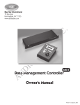
ProDesk™
SAT 5 Active Satellite
SUB 8 Active Subwoofer
Owner’s Manual for 2.1 (Stereo) Application
blue sky ProDesk™ SAT 5 Active Satellite & SUB 8 Active Subwoofer
Owners Manual for 2.1 (Stereo) Applications Issue 1, rev 3
Contents
1.
2.
3.
4.
5.
6.
7.
8.
9.
10.
11.
12.
13.
14.
Contents
Safety Instructions _ __ __ __ __ __ __ __ __ __ __ __ _ 3
Philosophy & Introduction _ __ __ __ __ __ __ __ __ _ 4
Important notes about ProDesk™
and this Owner’s Manual _ __ __ __ __ __ __ __ __ __ _ 4
Quick Setup _ __ __ __ __ __ __ __ __ __ __ __ __ __ _ 5
System Signal Connection Diagram _ __ __ __ __ __ _ 6
A Tour of SAT 5 _ __ __ __ __ __ __ __ __ __ __ __ __ _ 7
A Tour of SUB 8 _ __ __ __ __ __ __ __ __ __ __ __ __ _ 8
Expanded Setup Guide _ __ __ __ __ __ __ __ __ _ 10
Cable and Wiring Specifications _ __ __ __ __ __ _ 11
Technical Information _ __ __ __ __ __ __ __ __ __ _ 12
Satellite Cabinet Dimensions _ __ __ __ __ __ __ _ 13
Subwoofer Cabinet Dimensions _ __ __ __ __ __ _ 14
The Functional Volume Control * _ __ __ __ __ __ _ 15
Factory Service Instructions _ __ __ __ __ __ __ __ _ 16
General Contact Details _ __ __ __ __ __ __ __ __ _ 16
* The FVC is an optional upgrade and is not included with ProDesk™
blue sky ProDesk™ SAT 5 Active Satellite & SUB 8 Active Subwoofer
Owners Manual for 2.1 (Stereo) Applications Issue 1, rev 3
Safety Instructions
1
READ INSTRUCTIONS - Read all safety and operating instructions
before operating this product.
11.
SERVICING - Do not attempt to service this product yourself.
Opening or removing covers, including any over bottom or side
speaker drivers, may expose you to dangerous voltage or other
hazards. Refer all service to qualified service personnel.
2.
RETAIN INSTRUCTIONS - Retain these safety and operating
instructions for future reference.
3.
12.
HEED WARNINGS - Follow all warnings on this product and in the
operating instructions.
DAMAGE REQUIRING SERVICE - Unplug this product from the
wall outlet and refer servicing to qualified personnel under the
following conditions:
4.
FOLLOW INSTRUCTIONS - Follow all operating and use
instructions.
a.
b.
5.
ATTACHMENTS - Do not use attachments not recommended by
the product manufacturer as they may cause hazards.
c.
6.
WATER AND MOISTURE - Do not use this product near water - for
example, near a bathtub, washbowl, kitchen sink, or laundry tub;
in a wet basement; or near a swimming pool; and the like.
7.
ACCESSORIES - Do not place this product on an unstable cart,
stand, tripod, bracket, or table. The product may fall, causing
serious injury to a child or adult, and serious damage to the
product. Use only with accessories recommended by the
manufacturer, or sold with the product. Any mounting of the
product should follow the manufacturer’s instructions and should
use a mounting accessory recommended by the manufacturer.
8.
POWER SOURCE - This product should be operated only from the
type of power source indicated on the marking label. If you are
unsure of the type of power supply to your home, consult your
product dealer or local power company.
9.
OVERLOADING - Do not overload wall outlets or extension cords
as this can result in a risk of fire or electric shock.
10.
LIQUID ENTRY - Never spill any liquid of any kind on the product.
d.
e.
When the power-supply cord or plug is damaged.
If liquid has been spilled, or objects have fallen into this
product.
If the product does not operate normally by following the
operating instructions. Adjust only controls that are covered
by the operating instructions as an improper adjustment of
other controls may result in damage and will often require
extensive work by a qualified technician to restore the product to its normal operation.
If the product has been dropped or damaged in any way.
When the product exhibits a distinct change in performance
- this indicates a need for service.
13.
REPLACEMENT PARTS - When replacement parts are required be
sure the service technician has used replacement parts specified
by the manufacturer or have the same characteristics as the
original part. Unauthorized substitutions may result in risk of fire,
electric shock, or other hazard.
14.
SAFETY CHECK - Upon completion of any service or repairs to this
product, ask the service technician to perform safety checks to
determine that the product is in proper operating condition.
15.
HEAT - This product should be situated away from heat sources
such as radiators, heat registers, stoves, or other products that
produce heat.
Page 3
blue sky ProDesk™ SAT 5 Active Satellite & SUB 8 Active Subwoofer
Owners Manual for 2.1 (Stereo) Applications Issue 1, rev 3
1.
Philosophy &
Introduction
Blue Sky is a philosophy. We design each product to represent the highest
ratio possible of performance to cost, providing the highest value added to
our customers.
We will continually seek out opportunities to utilize the talent of the Blue Sky
team to realize this philosophy. Our customer’s value requirements will always
be our prime focus, and only those products that achieve our performance
value ratio will earn the right to carry the Blue Sky logo.
To that end we are proud to introduce ProDesk™, the first truly full-range
monitoring system specifically designed for critical mixing and monitoring on
the desktop. ProDesk™ brings the desktop user the same spectral performance
as Sky System One, with the only compromise being less output than its bigger
brother. ProDesk™ uses the same revolutionary design technologies that were
used in Sky System One. Ultra low distortion, proprietary woofers, superlative
Danish tweeters and highly optimized amplifiers specifically designed for this
application. ProDesk™ is the logical evolution of Blue Sky’s 2.1- integrated 3way system concept and when used with Blue Sky’s new BMC, can also offer
an extremely high performance 5.1 solution for desktop applications.
Thank you for choosing Blue Sky
Page 4
2.
Important notes about
ProDesk™ and this
Owner’s Manual
SAT 5 High Pass Filter Switch –
The SAT 5 includes a user selectable High Pass filter network. This filter network
can be switched “IN” or “OUT” of circuit. When the SAT 5 is used in a 2.1
system configuration, with the SUB 8, this switch must be in the “IN” position.
If the SAT 5 is used with the SUB 12 or the Blue Sky BMC, this switch must be
in the “OUT” position. This is because the SUB 8, which is part of ProDesk™
does not include the High Pass Filter networks, which are included as part of
the SUB 12 and the Blue Sky BMC.
SUB 8 Left and Right Channel Outputs –
The SUB 8 is not compatible with the Blue Sky SAT 6.5. This is because the SUB
8 does not include the requisite 80Hz High Pass filter networks for the Left and
Right channel outputs. These High Pass filters are included in the SAT 5 and
therefore the lack of filters in the SUB 8 does not represent a problem when
the SUB 8 and SAT 5 are used together.
Applications addressed in this manual –
This manual is for 2.1 system setup only. If you are using the ProDesk system in
a 5.1 channel setup please follow the directions and instruction provided with
the Blue Sky Bass-Management Controller. For more information on the BMC,
please visit www.abluesky.com
blue sky ProDesk™ SAT 5 Active Satellite & SUB 8 Active Subwoofer
Owners Manual for 2.1 (Stereo) Applications Issue 1, rev 3
3.
Quick Setup
1.
Carefully remove the SAT 5 Active Satellite and the SUB 8 Active
Subwoofer from their respective packaging. Please make sure to
retain all packaging materials for future shipping requirements.
2.
The SAT 5 and SUB 8 leave the Blue Sky factory fully calibrated.
With the gain controls set to the reference mark (which is at 12
o’clock on the gain control) on the subwoofer and monitor
speakers, a 200mV -7dBu pink noise signal, with a bandwidth
of 500 to 2kHz, will yield 90dB SPL at 1 meter for the satellite.
Because most small monitoring rooms have some gain at low
frequency a good starting point for the subwoofer level is -3dB
from the reference position.
3.
The SAT 5 and SUB 8 use XLR connectors. You will need a total
of four (4) XLR cables for a stereo monitoring configuration (not
supplied).
4.
The first step in the installation process is to position the active
subwoofer. Although you have great flexibility in where the
active subwoofer is positioned, a good starting point is centered
between the left and right satellite speakers. This could be under
the console, behind the console, etc.
5.
Once the subwoofer is in position; connect two XLR cables from
the left and right monitor outputs on the mixing console or digital
workstation to the Left and Right inputs on the subwoofer. Then
connect the remaining two XLR cables to the left and right satellite
outputs of the subwoofer. You will connect these cables at the
end of Step 6. Finally, Plug in the power cord to the IEC connector
on the subwoofer.
6.
7.
Next, place the SAT 5 Active Satellite Speakers into position.
The recommended position for the monitors is based on ITU
standards and sets the speakers at 60 degrees from the listener,
forming an equilateral triangle (a triangle with equal sides). See
Figure 1. Fortunately, this setup eliminates most of the math and
is easily simplified to the following guidelines: If you want to sit
1 meter (39.37 inches) from the speakers, place the speakers 1
meter apart. If you want to sit 6 ft from the speakers, place the
speakers 6 ft apart. Etc. The active monitors can be positioned
on the console, on stands, etc. Ideally the SAT 5 active monitors
should be at seated ear height. If this is not possible, tilting
the cabinet at the listening area can improve high-frequency
coverage.
Once the left and right speakers are in position, plug the two XLR
cables from the subwoofers’ Left and Right outputs into each
of the SAT 5 inputs, and then plug the power cord into the IEC
connector on the SAT 5. Confirm the system is wired as shown in
System Signal Connection Diagram on - page 6.
IMPORTANT! Confirm that the High-Pass filter switch is on the “IN”
circuit position. This switch will turn on the 80Hz High-Pass filter
that is required when using the SAT 5 in a 2.1 system with the
SUB 8. This switch should be in the “OUT” position only when the
SAT 5 is used with the SUB 12 or in a 5.1 system when being used
with the BMC. Visit www.abluesky.com for more information on
the BMC and SUB 12.
8.
At this point the Blue Sky monitoring system is correctly
configured, and ready for the final step in the installation. Prior to
plugging the system into the wall, and powering up the system,
do a quick check of all connections.
9.
If everything is correct, plug in all power cords. Do not turn
on the power switches, yet! Some mixers and out-board
equipment such as D-to-A converters and equalizers generate
loud rail-to-rail pops when they initially turn-on. Depending
on the level and the gain settings of the monitors, these pops
could damage the tweeters in the SAT 5 monitors. To avoid this,
always turn on equipment in the following sequence: Mixer 1st,
subwoofer 2nd, and satellite speakers last.
10.
At this point the Blue Sky monitoring system is fully operational,
and ready for use. Begin by playing familiar pieces of music,
which can assist you in the fine-tuning and exact positioning of
both the active monitors and active subwoofer. It is important to
remember that the positioning of the subwoofer in the room will
impact the subwoofer level. You may find it necessary to increase
or decrease the level from the reference position. This is OK, and
is anticipated.
11.
If a more exacting setup is required, a pink noise generator, used
in conjunction with a real time analyzer can be used to fully
optimize the system (See Page 10 - Expanded Setup Guide).
12.
Just remember - Use your ears, they are the best audio tool you
have and you will be amazed how accurate the setup can be if
you use familiar audio material during the setup of the system.
Page 5
blue sky ProDesk™ SAT 5 Active Satellite & SUB 8 Active Subwoofer
Owners Manual for 2.1 (Stereo) Applications Issue 1, rev 3
13.
Congratulations! You have now completed the set up of one of
the world’s finest monitoring systems.
TO SOURCE
Page 6
4.
System Signal
Connection Diagram
blue sky ProDesk™ SAT 5 Active Satellite & SUB 8 Active Subwoofer
Owners Manual for 2.1 (Stereo) Applications Issue 1, rev 3
5.
A Tour of SAT 5
sat 5
1
active monitor
60W+60W
bi-amplified
BALANCED INPUT
IN
2
OUT
80Hz Filter
REF
-3dB
GAIN
3
OFF
-6dB
-9dB
-12dB
-15dB
-18dB -21
WARNING:To reduce the risk of fire or electrical
shock, do not expose this equipment to rain or
moisture. Do not remove cover. No user serviceable
parts inside. Refer servicing to qualified personnel.
CAUTION
RISK OF ELECTRIC SHOCK
DO NOT OPEN
!
AVIS: RISQUE DE CHOC ELECTRIQUE
NE PAS OUVRIR
120
VAC
60Hz
85
WATTS
4
designed in the USA
ON
5
blue sky international
200 Sea Lane
Farmingdale, New York 11735
T 2A L 250 V
Replace with
Same Rating
made in China
and Type
6
1.
2.
3.
INPUT - The XLR input is electronically balanced and should
be connected to the output of the subwoofer or other bassmanagement controller. Do not connect more than one source
to this input. Refer to the wiring table below for wiring custom
cables and connectors.
HIGH PASS FILTER SWITCH - This switch will turn on the 80Hz
High-Pass filter that is required when using the SAT 5 in a 2.1
system with the SUB 8. This switch should be in the “OUT”
position only when the SAT 5 is used with the SUB 12 or in a 5.1
system when being used with the BMC. Visit www.abluesky.com
for more information on the BMC and SUB 12.
GAIN & POWER CONTROL & LED - This knob controls input
sensitivity. When set to the reference position, a 200mv signal at
the input equals 90dB of output at one meter. Below the knob is
the power indicator LED.
4.
5.
6.
7.
IEC POWER TERMINAL - Connect to 120 Volt AC / 60Hz power
source, rated for 85 WATTS. Use the included IEC Power Cable.
FUSE – 2.0 Amp Slow Blow Fuse - Replace with same rating and
type. This fuse is for 120 VAC / 60Hz operation only. For products
purchased in countries outside North America, please see the
FUSE and POWER addendum included with this product.
POWER SWITCH - Controls the power to both amplifiers and all
internal electronics.
OmniMount® INSERTS (located on the bottom of the speaker
cabinet) – The SAT 5 comes standard with four ¼ X 20 inserts
that match OmniMount® Series 30 brackets (formerly known as
the 75 series). OmniMount® Series 30 brackets are rated for up
to 25 pounds of weight. For more information regarding the many
mounting brackets available from OmniMount®, please visit the
Omnimount® website www.omnimount.com, or contact your
pro audio retailer.
Page 7
blue sky ProDesk™ SAT 5 Active Satellite & SUB 8 Active Subwoofer
Owners Manual for 2.1 (Stereo) Applications Issue 1, rev 3
6.
A Tour of SUB 8
3
R
4
sub 8
active subwoofer
100 watt
5
1
RIGHT
IN
RIGHT
OUT
LEFT
IN
LEFT
OUT
SUB
IN
SUB
OUT
SUB
GAIN
REF
OFF
-3
-6
-9
-12
-15
-18
-24
80 Hz
24 dB/OCT
2
8
6
REMOTE
9
Replace Only with
Same Rating and Type
7
WARNING:To reduce the risk of fire or electrical
shock, do not expose this equipment to rain or
moisture. Do not remove cover. No user serviceable
parts inside. Refer servicing to qualified personnel.
ON
T 2 A 250 V
AVIS: RISQUE DE CHOC ELECTRIQUE
NE PAS OUVRIR
CAUTION
RISK OF ELECTRIC SHOCK
DO NOT OPEN
!
120
VAC
50/60Hz
200
WATTS
blue sky international
200 Sea Lan e
Farmingdale, New York 11735
Page 8
designed in the USA
made in China
blue sky ProDesk™ SAT 5 Active Satellite & SUB 8 Active Subwoofer
Owners Manual for 2.1 (Stereo) Applications Issue 1, rev 3
1.
RIGHT/LEFT IN - These XLR inputs should be connected to the
right/left output of your console or digital workstation. The inputs
are electronically balanced. Do not connect more than one
source to these inputs. Refer to the wiring table below for wiring
custom cables and connectors.
2.
RIGHT/LEFT OUT - This XLR output should be connected to the
right/ left input of the active satellite speaker. The outputs are
electronically balanced. These outputs are not bandwidth limited
and are designed to be used with the SAT 5 or other monitor
that has an 80Hz internal high pass filter network. Refer to the
wiring table in bullet point 1 for wiring custom cables and
connectors.
3.
SUB IN - This XLR input should be connected to either the
subwoofer output of an external bass-management controller
or the daisy-chain output (SUB OUT) of another Blue Sky Active
Subwoofer. This input is electronically balanced. This input is fullbandwidth (up to approximately 200Hz) and does not use a low
pass filter. Refer to the wiring table in bullet point 1 for wiring
custom cables and connectors.
4.
SUB OUT - A Subwoofer output for connecting additional
subwoofers. This should be connected to the SUB IN of an
additional Blue Sky SUB 8.
5.
SUB GAIN CONTROL & POWER LED - This knob controls the
input sensitivity of the subwoofer amplifier only. When set to the
reference position, a 100mv signal at the input equals 90dB of
output at one meter. Next to the knob is the power indicator LED.
6.
FUNCTIONAL VOLUME CONTROL (FVC) RJ-11 Connector Jack
- This standard six conductor RJ-11 jack is used to connect the
subwoofer to the optional FVC. The remote control cable length
should not exceed 100 Feet. For more information on the FVC,
please turn to page 15 “The Functional Volume Control”.
7.
POWER SWITCH - This switch controls the power to the
subwoofer amplifier and all internal electronics.
8.
FUSE - 2.0 Amp Slow Blow Fuse - Replace with same rating
and type. This fuse is for 120 VAC / 60Hz operation only. For
products purchased in countries outside North America, please
see the FUSE and POWER addendum included with this product.
9.
IEC POWER TERMINAL - Connect to 120 Volt AC / 60Hz power
source, rated for 200 WATTS. Use the included IEC Power Cable.
10.
¼ X 20 INSERTS - Located on the bottom of the subwoofer
cabinet are four ¼ X 20 inserts for spiked or rubber feet.
Page 9
blue sky ProDesk™ SAT 5 Active Satellite & SUB 8 Active Subwoofer
Owners Manual for 2.1 (Stereo) Applications Issue 1, rev 3
7.
Expanded Setup Guide
After completing the setup as specified in the Quick Setup (Page 5), a
more accurate setup can be performed using a Sound Pressure Level
meter (SPL meter), 1/3 Octave Real Time Analyzer (RTA) and a pink noise
generator. This setup guide should be used for 2 Channel systems with
one or more subwoofers. If you need information regarding setting up a 5.1
channel system, please consult the manual that comes with the Blue Sky Bass
Management Controller.
1.
Confirm that the satellite and subwoofer speakers have
been placed as recommended in the Quick Setup (page
5). Additionally, confirm that the system has been wired as
recommended in the Quick Setup (page 5).
2.
Before starting the calibration process, turn the level down on the
satellite and the subwoofer speakers. High-level test signals can
damage the speakers, and more importantly your ears.
3.
Patch a pink noise generator, tape or other source with at least 60
seconds of 0dBu Pink Noise into your console. If you are using a
digital source, the test signal should measure -20dB FS (0dB FS =
Full Scale Digital).
4.
Turn on the pink noise source and confirm that the console, or
digital workstation is generating -20dB FS / 0dBVU at the output
meters.
5.
Slowly bring up the gain of the left satellite speaker only. Bring up
the level until you measure 85dB on the C scale, with the response
set to Slow. SPL should be measured at the mix position, with
the SPL meter at arms length, with the microphone at seated ear
height, angled at approximately 45 degrees, and pointed at the
center point between the left and right speakers. If you are using
an RTA align the level of the speakers to 70dB reference line on the
analyzer.
6.
Repeat step 5 for the right speaker. (Make sure that you only align
one channel at a time, do not run signal through the left channel
while calibrating the right channel!)
7.
Now, that you have set the approximate level for the right and left
speakers, it is time to set the level for the subwoofer.
8.
If you are using an SPL meter proceed to step 10. If you are using a RTA
turn on the pink noise generator to the left or right channel. Confirm
that the channel, without the subwoofer running, has a response,
which roughly aligns with the 70dB Ref Line. Now, bring up the level
of the subwoofer until its average response aligns with the 70dB
Reference Line. A note about subwoofer response: The response
of the subwoofer is strongly affected by the acoustics of the room.
Blue Sky satellite/subwoofer systems are designed to minimize the
effects of room acoustics and allow you the greatest chance of having
smooth full-range frequency response. Experimenting with subwoofer
placement can yield smoother frequency response.
Page 10
9.
If you are using an SPL meter to calibrate your system, disconnect
the signal going to the left and right satellite speakers. Turn on
the pink noise generator to either the left or right speaker. Now,
bring up the gain of the subwoofer until you are measuring 79dB
(C weighted - Slow). Because of the nature of pink noise, it is
important to measure for an extended period of time. You will
notice that the meter level will change continuously, so you may
need to do a mental average. After aligning the subwoofer
reconnect both satellite speakers.
10.
Now, it is time to listen... When listening to a properly
aligned Blue Sky satellite/subwoofer system, you will
notice extended low frequency response, wide dynamic
range, a deep sound stage and very smooth transition from
subwoofer to satellite speaker.
11.
Congratulations! You have now completed the set up of one of
the world’s finest monitoring systems. If you have any questions,
please do not hesitate to contact us directly with your questions.
(516) 249-1399 (9:00am to 5:30pm EST)
blue sky ProDesk™ SAT 5 Active Satellite & SUB 8 Active Subwoofer
Owners Manual for 2.1 (Stereo) Applications Issue 1, rev 3
8.
Cable and Wiring
Specifications
Use high-quality, shielded cables to connect your console, workstation or
other source to your Blue Sky monitoring system. Foil-shielded cables, such
as Belden 8451, 8761, or 9501 should do quite well. Other high quality
cables are available and those that incorporate better shielding will yield an
overall higher noise rejection, lowering your systems susceptibility to external
interference. Another important tip to keep in mind when wiring your system
is to route all line level cables away from the AC and other power sources, this
will reduce the probability of having AC hum emanating from your monitoring
system.
Page 11
blue sky ProDesk™ SAT 5 Active Satellite & SUB 8 Active Subwoofer
Owners Manual for 2.1 (Stereo) Applications Issue 1, rev 3
9.
Technical Information
As mentioned in the introduction of this manual, Blue Sky International’s high
performance to cost ratio is based on a philosophy that says that inexpensive
products should NOT be made from “inferior” components. This counter
intuitive attitude means that the highest quality components and manufacturing
techniques available are used in all aspects of the development and production
of this reference quality monitoring system. The specifications say it all, these
speakers are not toys - they are tools. We hope this new set of tools serves you
for a long time and that all the components, engineering and manufacturing
resources that have been used to make them shines through in every day use.
This next section outlines the components, specifications and performance
data that make this product such a uniquely high value.
In order to continually improve all of its products Blue Sky reserves the right to
change these specifications without notice.
SAT 5 Active Satellite
Enclosure
*
Solid .75” MDF construction with 1” front and rear
baffle
*
¼”x 20 inserts for attachment of OmniMount type 30 brackets
(formerly known as the 75 series).
*
Dimensions are 10.88” H x 6.62” W x 10.23” D (11.88” with
heatsink and tweeter wave guide)
*
Weight 24lbs. / 11kg
.75” Tweeter
*
Dual concentric diaphragm with integral wave guide
*
High power ferrite magnet assembly
*
Fully video shielded
5.25” Hemispherical Woofer
*
Cast aluminum frame
*
1.5” voice coil
*
Copper shorting ring
*
Aluminum alloy cone
*
Fully video shielded
*
Vented motor structure
Satellite Amplifier
*
Dual 60 Watts into 4-Ohm
*
.01% THD + noise at rated power @ 1 kHz
*
XLR balanced input
*
Adjustable gain control
*
B00® optimized crossover
*
80Hz filter bypass switch
General Specifications
Input Impedance
40k Ohms balanced
Common Mode Rejection Ratio 40dB typical 60Hz
Voltage Sensitivity
200mV = 90dB SPL @ 1M
Maximum Input Level
+24dBu balanced
Frequency Response
+/- 1.5dB 200Hz to 10kHz
+/- 3.0dB 80Hz to 20kHz
Low Frequency Cutoff
80Hz
Internal High Pass Filter
80Hz 2nd order (selectable)
Internal Crossover
1.8kHz
Page 12
SUB 8 - 8” Active Subwoofer
Enclosure
*
.75” MDF with 1” front and rear baffle
*
Isolation feet include
*
Dimensions: 13” H x 16” W x 13.37” D (15.76” with heatsink and grill)
*
Weight 48.5lbs / 22kg
8” Hemispherical Woofer
*
8-inch high excursion woofer
*
Vented motor structure
*
Cast aluminum frame
*
2.0 “ voice coil
*
Aluminum alloy cone
Amplifier
*
Discrete symmetrical bipolar design
*
100 Watts RMS into 4-Ohm
*
01% THD + noise at rated power @ 100 Hz
*
XLR balanced input
*
Adjustable gain control
*
B00® optimized crossover
*
Voltage Sensitivity
100mv=90dB SPL@1m
*
Frequency Response (direct IN - anechoic) 0 to 200Hz
*
Typical in room response (direct IN )
35Hz to 200Hz
(1500 cubic feet)
Bass-Management
*
Input impedance
20K balanced
*
Common mode rejection
40dB typical @ 60Hz
*
Maximum Input Level
+24dBu balanced
*
Output Impedance
200 Ohms balanced
*
Nominal gain
0dB
*
High Pass filter
None (built into SAT 5)
*
Low Pass filter
80Hz 4th order
*
Direct In low pass filter
None
blue sky ProDesk™ SAT 5 Active Satellite & SUB 8 Active Subwoofer
Owners Manual for 2.1 (Stereo) Applications Issue 1, rev 3
10. Satellite Cabinet
Dimensions
6.62" (168.26mm)
11.43" (290.37mm)
1.20" (30.48mm)
10.88" (276.24mm)
10.88" (276.24mm)
10.23" (259.89mm)
2.06" (52.33mm)
2.00" (50.80mm)
2.13" (54.08mm)
.99" (25.21mm)
3.46" (87.80mm)
Page 13
blue sky ProDesk™ SAT 5 Active Satellite & SUB 8 Active Subwoofer
Owners Manual for 2.1 (Stereo) Applications Issue 1, rev 3
11. Subwoofer Cabinet
Dimensions
16.00" (406.40mm)
1.00" (25.40mm)
13.00" (330.20mm)
13.37" (339.72mm)
12.50" (317.50mm)
1.37" (34.77mm
14.76" (374.95mm)
1.75" (44.45mm)
12.50" (317.50mm)
1/4" X 20 INSERT
10.25" (260.35mm)
10.58" (268.84mm)
Page 14
blue sky ProDesk™ SAT 5 Active Satellite & SUB 8 Active Subwoofer
Owners Manual for 2.1 (Stereo) Applications Issue 1, rev 3
12. The Functional Volume
Control
Introduction
The Functional Volume Control (FVC) is a simple yet effective hardwired
remote control that is designed to be used with the SUB 8 as part of a
ProDesk™ 2.1 System (future subwoofer models may also take advantage of
this feature). For 5.1 channel systems the FVC should not be used and
instead the Blue Sky BMC should be used. (For more information on the
Blue Sky BMC, please visit www.abluesky.com)
-30
-40
-24
-15
-50
Connection and Operation
The FVC is designed to connect to the SUB 8 via standard 6 conductor modem
cable and RJ11 jack (included with the remote). The maximum length for this
wire should not exceed 100 feet.
-21
-18
-12
-9
-6
-3
-60
-70
0
Once connected, the Functional Volume Control (FVC) controls the gain of the
Left and Right input channels of the Sub 8. The FVC does not control the gain
of the external / direct SUB IN channel. However, the FVC will control the level
of the Left & Right summed and derived subwoofer signal that is sent to the
SUB OUT jack and the internal subwoofer amplifier. Calibration levels between
the SUB 8 and SAT 5 are not affected by the FVC and calibration should be
done as stated in the ProDesk™ manual.
Functional Volume Control | FVC
Below is an outline that shows how the SUB 8 and FVC interact, either when the
remote is connected or not.
1.
Power Up
A.
Volume Control Not Connected
1. L/R gain defaults to 0dB (unity gain)
1.242 (31.543)
B.
4.016 (101.994)
Volume Control is connected
1. L/R channels are muted
2. LED on Remote Flashes
3. User must turn Gain control fully counterclockwise
until the LED stops flashing and is on continuously
4. The FVC is now operating normally
.675 (17.145)
-30
-40
3.
FVC cable is disconnected during normal operation
A.
When disconnected, gain stays at current level until
power is recycled or the FVC is reconnected
Volume control is attached after power up
A.
Volume control will not operate and LED will flash
B.
User must turn Gain control fully counterclockwise until
the LED stops flashing and is on continuously
C.
The FVC is now operating normally
-21
-18
-15
-50
-12
-9
6.496 (165.002)
-6
-3
-60
-70
8
2.
-24
0
1.956 (49.672)
Page 15
blue sky ProDesk™ SAT 5 Active Satellite & SUB 8 Active Subwoofer
Owners Manual for 2.1 (Stereo) Applications Issue 1, rev 3
13. Factory Service
Instructions
14. General Contact
Details
Service for the U.S. versions of Blue Sky products is available only from our
authorized distributor, Group One Ltd., located in Farmingdale, New York.
(Service for Blue Sky products outside the United States can be obtained
through local dealers or distributors.) If your monitor needs service, follow
these instructions:
For sales and other enquiries, please contact Blue Sky at:
1.
2.
Review the manual and ensure that you have followed all setup
and operating instructions.
Call (516) 249-1399 9:00am to 5:30pm EST and ask for Customer
Service. Explain the problem and request an RA (Return
Authorization) number. It is important to have your product serial
number available when you call. You must have an RA number
before you can obtain service.
3.
Pack the product in its original packing material and box (do
not return the power cord or the manual). If you don’t have
the original packing material and/or box, please let Customer
Service know when you call for the RA number. Blue Sky is not
responsible for any damage that occurs due to non-factory
packaging.
4.
Include a legible note stating your name, shipping address (no
P.O. boxes), daytime phone number, RA number, and a detailed
description of the problem, including how it can be duplicated
5.
Write the RA number on the top of the carton.
6.
Ship the product to the address below. We recommend United
Parcel Service (UPS). Please insure the product regardless of
shipping method.
Blue Sky International
70 Sea Lane
Farmingdale, NY 11735
USA
tel:
fax:
email
516 249 3662
516 249 8870
[email protected]
To discover the very latest information check out our website at:
www.abluesky.com
Blue Sky International
ATTN: SERVICE DEPT / RA#
70 Sea Lane
Farmingdale, NY 11735
USA
7.
Turnaround time is three to five business days depending on the
problem. When calling for RA numbers, please ask Customer
Service what the turnaround time is. The serviced product will be
sent back to you via the same shipping method as received (i.e. if
you ship your monitor UPS Ground it will be returned UPS Ground,
UPS Red will be returned UPS Red etc...). This only applies to
products serviced under the warranty.
Copyright © 2001~2003 Blue Sky International
Page 16
blue sky ProDesk™ SAT 5 Active Satellite & SUB 8 Active Subwoofer
Owners Manual for 2.1 (Stereo) Applications Issue 1, rev 3
Page 17
Blue Sky International
70 Sea Lane
Farmingdale, NY 11735, USA
web
tel:
fax:
email:
www.abluesky.com
516 249 3662
516 249 8870
[email protected]