1
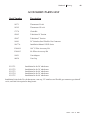
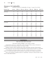
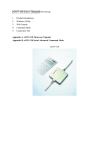
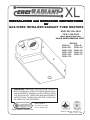
Section
INST
ALLA
TION and OPERA
TING INSTR
UCTIONS
INSTALLA
ALLATION
OPERATING
INSTRUCTIONS
for
GAS-FIRED INFRA-RED RADIANT TUBE HEATERS
ANSI Z83.20b-2004
CSA 2.34b-2004
MOST RECENT EDITION
PLACE NEAR HEATING UNIT
MODELS
ERXL-60,
ERXL-80
ERXL-80S,
ERXL-100
ERXL-100S, ERXL-125
ERXL-125S
ERXL-150
ERXL-150L, ERXL-175
ERXL-175L
WARNING:
IMPROPER INSTALLATION, ADJUSTMENT, ALTERATION, SERVICE OR MAINTENANCE CAN
CAUSE PROPERTY DAMAGE, INJURY OR DEATH. READ
THE INSTALLATION, OPERATING AND MAINTENANCE
INSTRUCTIONS THOROUGHLY BEFORE INSTALLING
OR SERVICING THE EQUIPMENT
4560 W.160th St.
Cleveland, Ohio 44135
Phone: 800-251-0001
Enerco Technical Products, Inc.
Stock No. 18677XL 8/05 Rev. A
18677 Rev. A 8/05
Section
18677
Rev. A 8/05
01
Section 1 Warnings
WARNING
FIRE OR EXPLOSION HAZARD
Can cause property damage, severe injury or death.
1)
Read this manual carefully before installing or servicing this equipment. Improper installation, service or maintenance can cause
property damage, injury or death.
2)
Check clearances given on the outside of each burner to make sure
the product is suitable for your application.
3)
Installer must be a trained, experience service technician or representative.
4)
All service must be performed only by a trained service technician or
representative.
5)
After installation is complete, check product operation as provided
in these instructions.
WARRANTY
ENERCO warrants the Infra-Red Heaters manufactured and sold by
its Industrial Heating Division will be free from defects in material and
workmanship.
ENERCO pro-rated tube warranty shall continue in effect until the
expiration of five (5) years from the date of shipment or original tube
heat exchangers by Enerco.
Parts, assemblies, control etc. furnished by ENERCO suppliers will
carry a one (1) year warranty or applicable warranties of the suppliers.
The sole responsibility of ENERCO under this warranty shall be to
replace or repair any part for which a written claim is made to ENERCO
within the time limit of the warranty, which is returned upon request to
ENERCO -- F.O.B. Cleveland, Ohio -- or F.O.B. an ENERCO authorized
service facility and which is proved to be defective upon inspection By
ENERCO.
This warranty shall not apply to any part or product which has been
subjected to misuse or neglect, damage by accident, or rendered defective
by reason of improper installation. This warrant is in lieu of any and all
other warranties, expressed or implied, and of any other responsibility by
ENERCO for parts or products sold by ENERCO, including consequential or special damages.
18677
Rev. A 8/05
Section 1 Warnings
02
WARNING
FAILURE TO FOLLOW THESE
INSTRUCTIONS CAN CAUSE PROPERTY
DAMAGE, SEVERE INJURY OR DEATH:
FIRE OR EXPLOSION HAZARD: Combustibles
Failure to maintain the specific minimum clearances to combustibles
could result in a serious fire hazard. Do not locate flammable or combustible materials within this distance. Do not locate in hazardous atmospheres
containing flammable vapors or combustible dust. Installations in public
garages or airplane hangers are permitted when in accordance with ANSI
Z83.6 and NFPA-409 and 88 codes.
FIRE OR EXPLOSION HAZARD: Vehicles
Minimum clearances must be maintained from vehicles parked below
the heater. Signs should be posted in storage areas to specify maximum
stacking height to maintain required clearances to combustibles.
FIRE OR EXPLOSION HAZARD: Gas Connection
There is an expansion of the radiant pipe with each firing cycle, and
this will cause the burner to move with respect to the gas line. This can
cause a gas leak resulting in an unsafe condition if the gas connection is not
made strictly in accordance with (Figure 18) of these instructions.
FIRE OR EXPLOSION HAZARD: Ignition
This appliance does not have a pilot. It is equipped with an ignition
device which automatically lights the burner. Do not try to light the burner
by hand.
MECHANICAL HAZARD: Suspension
Use appropriate suspension hardware, beam clamps (rod or perforated
strap) and turnbuckles at predetermined locations. The weight and normal
movement of the heating system may cause support failure if the following
minimum suspension requirements are not met: 1) distance between supports must be 10 ft. or less; 2) chain size must be 1/0 minimum or equivalent. Failure of the supports can cause property damage, severe injury, or
death.
More WARNINGS on next page
18677
Rev. A 8/05
03
Section 1 Warnings
IMPORTANT
FAILURE TO FOLLOW THESE
INSTRUCTIONS CAN CAUSE PROPERTY
DAMAGE OR PERSONAL INJURY
Do not use in an atmosphere containing halogenerated hydrocarbons or
other corrosive chemicals. Some compounds in the air can be drawn into the
equipment and can cause an accelerated rate of corrosion of some parts of the
heat exchanger. The use of such chemical compounds in or near the enclosure
should be avoided where a longer life of the burner, tubing and other parts is
desirable.
Caution should be used when running the system near combustible
material such as wood, paper, rubber, etc. Consideration should be given to
partitions, storage racks, hoists, building construction, etc. (Tabe 1, Section 3)
gives minimum acceptable clearances to combustibles. Clearances as shown
in Table 1 are not for use in four-sided enclosures.
If the building has a slight negative pressure or contaminants are present
in the air, an outside combustion air supply to the heater is strongly
reccomended.
CAUTION
FAILURE TO FOLLOW THESE
INSTRUCTIONS CAN CAUSE DAMAGE, TO
THE SYSTEM COMPONENTS
Do not high pressure test the gas piping with the burner connected.
Failure to follow this procedure will exceed the pressure rating of buner gas
controls and this will require complete replacement of these parts.
This heater is designed for heating non-residential indoors spaces. These
instrcutions, the layout drawing, local codes and ordinances, and applicable
standards such as apply to gas piping, electrical wiring, venting, etc., must be
thouroughly understood before proceeding with the installation.
18677
Rev. A 8/05
Section
TABLE OF CONTENTS
WARNINGS & WARRANTY
1
1-3
Read this sections carefully. Improper installation adjustment, operation or maintenance can cause property damage, injury or death
4
INDEX
INTRODUCTION
2
5
3
6-14
4
15-20
5
21-26
6
27
7
28-31
8
32-36
9
37-40
Checking Shipment - Installer Responsibility
INSTALLATION: Planning
National codes - Critical Considerations - Installation Procedure
Accessory parts Lists - Clearances to Combustibles - Parts list for packaged
Ener-Radiant III Heaters
INSTALLATION: Assembly
Assembly Overview - Couplings - Suspension - Tube Clamp
Turbulator - Burner
INSTALLATION: Venting & Ducting
General Requirements - Unvented Operation - Horizontal Venting
Vertical Venting - Common Venting - Outside Air Supply
INSTALLATION: Gas Piping
Sizing - Installation - Flex Gas Connection
INSTALLATION: Wiring
Line Voltage Thermostat Wiring - Low Voltage Thermostat Wiring
Burner Internal Wiring - Ladder Diagram
OPERATION/MAINTENANCE
Operation - Maintenance - Troubleshooting
APPENDICES
Replacement Parts I - Engineering Specifications II
General Specifications III
18677
Rev. A 8/05
04
05
Section 2 Introduction
INTRODUCTION
Section 2
Ener-Radiant XL models are low-cost, field assembled infrared heaters that are easy to install
and require only minimal maintenance. They are designed to provide years of economical
operation and trouble-free service.
Checking Shipment
Check the shipment against the Bill of Lading for shortages. Also check for external damage to
cartons. Note any shortages, and/or external damage to cartons on the Bill of Lading in the
presence of the delivery trucker. The delivery trucker should acknowledge any shortages or
damage by initializing this “noted” Bill of Lading. Immediately report any claims for damage
material, or shortages that were not evident at the time of shipment, to the carrier and your
ENERCO Factory Representative.
Installer Responsibility
All heaters and associated gas piping should be installed in accordance with applicable
specifications and this installation made only by firms (or individuals) well qualified in this type
of work. Consult local building inspectors, Fire Marshals or your local ENERCO Representative
for guidance.
Ener-Radiant XL heaters are installed on the basis of information given in a layout drawing,
which together with the cited codes and regulations, comprise the basic information needed to
complete the installation. The installer must furnish all needed material that is not furnished as
standard equipment, and it is his responsibility to see that such materials, as well as the
installation methods he uses result in a job that is workmanlike and in compliance with all
applicable codes.
ENERCO Factory Representatives have had training and experience in the application of this
equipment and can be called on for suggestions about installation which can save material and
money.
18677
Rev. A 8/05
Section 3 Planning
PLANNING
Section 3
The following codes and instructions should be followed when planning the installation of
the Ener-Radiant XL heater. In addition to these instructions, the warnings in (Section 1 )
must be carefully adhered to since improper installation may lead to property damage, injury
or death.
National Standards and Applicable Codes
Gas Codes: The type of gas appearing on the nameplate must be the type of gas used. Installation
must comply with local codes and recommendations of the local gas company, and the
National Fuel Gas Code, ANSI Z223.1 - latest revision, (same as NFPA bulletin 54).
•
Clearance between the heater and its vent and adjacent combustible material (which is
part of the building or its contents) shall be maintained to conform with the Standard for
Installation of Gas Appliances and Gas piping, NPFA-54 / ANSI Z223.1 - latest revision,
National Fuel Gas Code.
Aircraft Hangers: Installation in aircraft hangers must be in accordance with the Standard for Aircraft
hangers, ANSI / NFPA-409 - latest revision.
•
Heaters in aircraft storage or service areas shall be installed at a height of 10 feet above
the upper surface of wings or engine enclosures of the highest aircraft which may be
housed in the hanger. (This should be measured from the bottom of the heater to the
wing or engine enclosure, whichever is highest from the floor.)
•
In other sections of aircraft hangers, such as shops or offices, heaters must not be
installed less than 8 feet above the floor.
•
Heaters installed in aircraft hangers shall be located so as not to be subjected to damage
by aircraft, cranes, moveable scaffolding or other objects.
Public garages: Installations in garages must be made in accordance with the Standard for parking
Structures, NPFA-88A - latest revision or the Standard for Repair Garages, NFPA-88B latest revision.
•
Heaters must not be installed less than 8 feet above the floor. Minimum clearances to
combustibles must be maintained from vehicles parked below heater.
•
When installed over hoists, minimum clearances to combustibles must be maintained
from the uppermost point on the hoist.
Electrical: the heater must be electrically grounded in accordance with the National Electrical
Code, ANSI / NPFA-70 - latest revision. Wiring must conform to the most current
National Electrical Code, local ordinances, and any special diagrams furnished.
Venting: the venting must be installed in accordance with NPFA-54 / ANSI-Z223.1 - latest
revision, National Fuel Gas Code. Partial information with regard to this code is
provided in (Section 5) of this installation manual with regard to size and configurations
for venting arrangements.
•
Any portion of flue pipe passing through a combustible wall must be dual insulated or
have an approved thimble. Refer to ANSI-Z223.1 - latest revision.
Hazardous Where there is the possibility of exposure to combustible airborne material or vapor,
Locations: consult the local Fire Marshal, the fire insurance carrier or other authorities for approval
of the proposed installation.
18677
Rev. A 8/05
06
07
Section 3 Planning
Critical Considerations
Ener-Radiant XL is a suspended heater. Therefore, its stability, flexibility, and safety are very
important. Before starting installation, be sure the system can meet the following requirements.
•
Maintain specified clearances to combustibles, and safe distance from heat-sensitive
material, equipment and work stations.
•
Provide a suspension with vertical length of chain or swinging rod which has at least 2
inches of horizontal travel for each burner in a straight run. Be sure the suspension system
is sufficiently flexible to accommodate thermal expansion which occurs as the system
heats up (see Figure 5).
•
Provide access to burners for servicing, preferable on both sides, above and behind for
burner removal.
•
Provide a minimum of 18 inches of clearances between burners and building walls.
(Always observe minimum clearances to combustibles).
•
Be sure the heater has a downward pitch of one-half inch per 20 feet away from the burner.
•
Provide signs in storage areas to specify maximum stacking height to maintain required
clearances to combustibles.
•
Plan location supports (see Figure 2). Locate a support near all elbows.
Installation Procedure
Take maximum advantage of the building upper structure, beams, joist, purlins, etc., from
which to suspend the heater. There is no unique sequence for installation of the tubing. On-site
observation will usually reveal a logical sequence. Begin the installation at the most critical
dimension. This could save time. Watch for swinging doors, overhead cranes, car lifts, etc.
Reflectors and tubing can be installed as you move along. Carefully adjust system pitch at each
position to level the heater. Pitch down one half inch in 20 feet (away from Burner)
Don’t
•
Pressure test the gas line using high pressure (greater than 1/2 PSIG) without closing the
high pressure shut-off cocks. Failure to do so will result in damage to the burners.
Do
•
Familiarize yourself with local and national codes.
•
Develop a planned procedure which will conserve material and labor on the job.
•
Check to see that all material and equipment is on the job before starting installation.
•
Allow for thermal expansion of the hot tube.
•
Install the gas connector only as shown in instructions (see Figure 18).
•
Have slip joints where required between reflectors keep them from buckling or coming
apart.
•
Provide 1 sq inch of free air opening to each 1,000 BTU/hr of heater input (but not less
than 100 sq inches) in enclosed spaces. One opening should be within 12 inches of the top
and within 12 inches of the bottom of the enclosure.
18677
Rev. A 8/05
Section 3 Planning
08
ACCESSORY PARTS LIST
Stock Number
Description
10371
Thermostat 24 volt
10392
Thermostat 120 volt
17370
Chain Kit
03445
Turbulator 10’ Section
03447
Turbulator 5’ Section
16401
24” Stainless Steel Flexible Gas Connector
18677A
Installation Manual / ER3LSeries
F106414
180o U-Tube Accessory Kit
F106415
90o Elbow Accessory Kit
19021
Vent Adapter
06430
Vent Cap
F111751
F111752
F111753
F111754
F111755
Installation kit for 20’ tube heater
Installation kit for 30’ tube heater
Installation kit for 40’ tube heater
Installation kit for 50’ tube heater
Installation kit for 60’ tube heater
Installation kit includes 24-volt thermostat, vent cap, 24” stainless steel flexible gas connector, gas shutoff
vavle, and chair kits required to hang heater.
18677
Rev. A 8/05
09
Section 3 Planning
Clearances To Combustibles
TABLE 1:
Refelctor Type
Minimum Clearances to Combustibles (Use figure 1 on page 10 as a Guide)
Position
ERXL-60
ERXL-80
ERXL-100
ERXL-125
ERXL-150
ERXL-175
Standard Reflector
(Horizontal)
A
B
C
D
6”
30”
55”
30”
6”
36”
55”
36”
6”
36”
74”
36”
6”
36”
87”
36”
6”
36”
87”
36”
8”
36”
87”
36”
45o Reflector Tilt
A
B
C
E
F
12”
30”
55”
36”
60”
18”
36”
55”
36”
60”
18”
36”
74”
36”
60”
18”
36”
87”
36”
60”
18”
36”
87”
36”
60”
18”
36”
87”
36”
60”
U-Tube Standard
(Horizontal)
A
B
C
D
6”
30”
55”
30”
6”
36”
55”
36”
6”
36”
74”
36”
6”
36”
87”
36”
6”
36”
87”
36”
8”
36”
87”
36”
U-Tube Opposite 45o
A
B
C
F
12”
30”
55”
60”
18”
36”
55”
60”
18”
36”
74”
60”
18”
36”
87”
60”
18”
36”
87”
60”
18”
36”
87”
60”
U-Tube Full 45o
A
B
C
E
F
12”
30”
55”
36”
60”
18”
36”
55”
36”
60”
18”
36”
74”
36”
60”
18”
36”
87”
36”
60”
18”
36”
87”
36”
60”
18”
36”
87”
36”
60”
36”
36”
36”
36”
36”
36”
Unvented
Above A
WARNING
FIRE OR EXPLOSION HAZARD
Can cause property damage, severe injury or death.
In all situations, clearances to combustibles must be maintained. Failure to observe clearances to
combustibles may result in property damage, severe injury, or death.
Minimum clearances must be maintained from vehicles parked below the heater. Signs should be
posted in storage areas to specify maximum stacking height to maintain required clearances to combustibles.
Caution should be used when running the system near combustible materials such as wood, paper,
rubber, etc. Consideration should be given to partitions, storage racks, hoists, building construction, etc.
Table 1 gives minimum acceptable clearances to combustibles. Clearances as shown in Table 1 are not
for use in four-sided enclosures.
18677
Rev. A 8/05
Section 3 Planning
10
Clearances To Combustibles
FIGURE1:
Clearances to Combustibles (Refer to Table 1 on page 9)
Standard Reflector
45o Reflector Tilt
“U”-Tube, Standard
“U”-Tube, Opposite 45o
“U”-Tube, Full 45o
Front and Back Clearance
18677
Rev. A 8/05
11
Section 3 Planning
Parts List for Packaged Ener-Radiant XL Tube Heaters
ITEM STOCK
1
F107400XL
DESCRIPTION
ERXL-60 NG COMP / 20’
NUMBER REQUIRED
X
2
F107401XL
ERXL-60 LP COMP / 20’
X
3
F107402XL
ERXL-80 NG COMP / 30’
4
F107403XL
ERXL-80 LP COMP / 30’
5
F107412XL
ERXL-80S, NG COMP / 20’
6
F107413XL
ERXL-80S, LP COMP / 20’
7
F107414XL
ERXL-100S, NG COMP /30’
8
F107415XL
ERXL-100S, LP COMP / 30’
9
F102650XL
ERXL-60 NG / BRN & Cont Box
10
F102651XL
ERXL-60 LP / BRN & Cont Box
11
F102652XL
ERXL-80S, ER3-80 NG /BRN & Cont & Box
12
F102653XL
ERXL-80S, ER3-80 LP / BRN & Cont & Box
13
F102654XL
ERXL-100S / BRN & Cont Box / NG
14
F102655XL
ERXL-100S / BRN & Cont Box / LP
15
F106401XL
ERXL-100S / TUBE SYS ONLY / 30’
16
F106404XL
ERXL-60, 80S /TUBE SYS ONLY / 30’
17
F106405XL
ERXL-80 / TUBE SYS ONLY / 30’
18
00418A
REFELECTOR / T.H.
2
19
03445
TURBULATOR BAFFLE 10’
1
20
03447
TURBULATOR BAFFLE 5’
21
06413
TUBE H.E. 4” O.D. x 10’
1
1
2
2
1
22
14585
HANGER / TUBE & REFELECTOR
4
4
6
6
23
02753
FRONT CASTING
1
1
1
24
14612
TUBE COUPLING ASSEMBLY
1
1
2
X
X
X
X
X
X
1
1
1
1
1
1
1
1
1
1
1
1
3
3
1
1
1
2
2
4
4
6
6
1
1
1
1
1
2
1
1
2
2
1
1
1
1
2
3
3
2
2
1
1
1
1
1
*Items 15, 16, 17 include the following items: 18, 19, 20, 21, 22, 24.
18677
Rev. A 8/05
Section 3 Planning
12
Figure “A” - Assembly
Model ERXL-60, ERXL-80S
Figure “B” - Assembly
Model ERXL-80
Figure “C” - Assembly
Model ERXL-100S
See Page 11
for PARTS LIST
18677
Rev. A 8/05
13
Section 3 Planning
Parts List for Packaged Ener-Radiant XL Tube Heaters
ITEM STOCK
DESCRIPTION
1
F107404XL ERXL-100 NG COMP / 40’
NUMBER REQUIRED
X
2
F107405XL ERXL-100 LP COMP / 40’
X
3
F107406XL ERXL-125 NG COMP / 50’
4
F107407XL ERXL-125 LP COMP / 50’
5
F107408XL ERXL-150, NG COMP / 50’
6
F107409XL ERXL-150, LP COMP / 50’
7
F107420XL ERXL-175, NG COMP / 50’
8
F107421XL ERXL-175, LP COMP / 50’
9
F107416XL ERXL-125S NG COMP / 40’
10
F107417XL ERXL-125S LP COMP / 40’
11
F107418XL ERXL-150L NG COMP / 60’
12
F107419XL ERXL-150L LP COMP / 60’
13
F107422XL ERXL-175L NG COMP / 60’
14
F107423XL ERXL-175L LP COMP / 60’
15
F102654XL ERXL-100 NG / BRN & CB
16
F102655XL ERXL-100 LP / BRN & CB
17
F102656XL ERXL-125S, ERXL-125 NG / BRN & CB
18
F102657XL ERXL-125S, ERXL-125 LP / BRN & CB
19
F102658XL ERXL-150L, ERXL-150 NG / BRN & CB
20
F102659XL ERXL-150L, ERXL-150 LP / BRN & CB
21
F102660XL ERXL-175L, ERXL-175 NG / BRN & CB
22
F102661XL ERXL-175S, ERXL-175 LP / BRN & CB
23
F106403
ERXL-150L / TUBE SYS / 60’
24
F106406
ERXL-100, ERXL-125S / TUBE SYS / 40’ 1
25
F106407
ERXL-125, ERXL-150 / TUBE SYS / 50’
26
00418A
REFLECTOR / T.H.
4
27
06413
TUBE H.E. 4” O.D. x 10’
28
06423
29
X
X
X
X
X
X
X
X
X
X
X
X
1
1
1
1
1
1
1
1
1
1
1
1
1
1
1
1
1
1
1
1
1
1
4
5
5
5
5
4
4
6
6
3
3
4
4
4
4
3
3
5
5
TRANSITION TUBE ASSEMBLY
1
1
1
1
1
1
1
1
1
1
14585
HANGER / TUBE & REFLECTOR
8
8
10 10 10 10
8
8
12 12
30
14587
TUBE SUPPORT -- 5”
1
1
1
1
1
1
1
1
1
1
31
14612
TUBE COUPLING ASSEMBLY
3
3
4
4
4
4
3
3
5
5
*Items 23, 24, 25 include the following items: 26, 27, 28, 29, 30.
18677
Rev. A 8/05
Section 3 Planning
14
Figure “D” - Assembly
Model ERXL-100, ERXL-125S
Figure “E” - Assembly
Model ERXL-125,
ERXL-150, ERXL-175
Figure “F” - Assembly
Model ERXL-150L, 175L
See Page 13
for PARTS LIST
18677
Rev. A 8/05
15
Section 4 Installation & Assembly
INSTALLATION & ASSEMBLY
FIGURE 2:
Section 4
Ener-Radiant XL Overview Key
FIGURE 2a: Ener-Radiant XL Model ERXL-60, ERXL-80S, Assembly Overview
20 ft. Exchanger length. 21 ft. - 4 in. Total Heater length. 4 Suspension points as indicated
FIGURE 2b: Ener-Radiant XL Model ERXL-80, Assembly Overview
30 ft. Exchanger length. 31 ft - 4 in. Total Heater length. 6 Suspension points as indicated.
18677
Rev. A 8/05
Section Section
4 Installation & Assembly
16
FIGURE 2c: Ener-Radiant XL Model ERXL-100S, Assembly Overview
30 ft. Exchanger length. 31 ft - 4 in. Total Heater length. 6 Suspension points as indicated.
FIGURE 2d: Ener-Radiant XL Model ERXL-100, ERXL-125S
40 ft. Exchanger length. 41 ft - 4 in. Total Heater length. 8 Suspension points as indicated.
FIGURE 2e: Ener-Radiant XL Model ERXL-125, ERXL-150, ERXL-175
50 ft. Exchanger length. 51 ft - 4 in. Total Heater length. 10 Suspension points as indicated.
FIGURE 2f: Ener-Radiant XL Model ERXL-150L, ERXL-175L
60 ft. Exchanger length. 61 ft - 4 in. Total Heater length. 12 Suspension points as indicated.
18677
Rev. A 8/05
17
Section 4 Installation & Assembly
Assemble the heater components as shown in Figures 2a, 2b, 2c, 2d, 2e and 2f. Optional reflector
configurations are shown in (Figure 1). Install appropriate suspension hardware, beam clamps,
chain or rod at predetermined locations. Adjustment of chain length will provide uniform pitch.
Couplings: Tube and tube fittings are connected by wrap-around couplings which clamp by means of a tapered,
hammer-driven lock member. The starting ends of the coupling and lock member are identified by
1/4” holes which are put together when starting assembly. Be sure the tube ends are in line and tube
ends butt against stop pin(s) inside coupling. The slide bar is to be hammer-driven to a point of
securing the coupling snugly to the tubes. Over-driving will result in distortion of the coupling or
slide bar lip to a point decreasing the holding capability of the coupling. Coupling should be tight
when the slide bar is + 2” from the end of the coupling. (See Figure 3).
FIGURE 3: Coupling Assembly
TURBULATOR BAFFLE ASSEMBLY INSTRUCTIONS
For ease of field installation, the turbulator should be installed in the tube before hanging the system.
Use the following procedure:
1) Assemble turbulator pieces by “twisting” matching ends together.
2) Insert a long wire (11 ft. minimum) down the length of the tube.
3) Attach the wire to the hole in the tab on the adapter piece.
4) Using the wire, pull the assembled turbulator into the tube from opposite side.
5) Pull the turbulator through until just the tab commes out. Detach the wire.
6) Bend the tab around the tubing. When installing the tube, the tab will be locked in place by the adapter.
18677
Rev. A 8/05
Section Section
4 Installation & Assembly
18
FIGURE 4: Installation of Elbow & Coupling (optional equipment)
Elbow package:
Stk. #F106415 Elbow Pacakge includes:
(1) elbow and (1) coupling. Install elbow into radiant tube sequence where
plans indicate a 90o bend (see Figure 4).
90o Elbow
Elbow Fitting Dimensions
Stk #F106414 U-Tube Package includes:
(1) U-tube and (1) coupling. Install U-tube elbow into radinat tube sequnce where
plans indicte a 180o bend (see Figure 4).
U-Tube Fitting Dimensions
180o U-Tube
18677
Rev. A 8/05
19
Section 4 Installation & Assembly
FIGURE 5: Typical Suspension Details
Chain Kit - Stk #17370
One chain kit will suspend one 10 ft.
section of tube and one 10 ft. section
of reflector.
FIGURE 6: Tube & reflector Hanger
18677
Rev. A 8/05
Section Section
4 Installation & Assembly
FIGURE 7: Mounting Flange / Tube Detail
1) Insert tube 06413 into front
casting to point (A).
2) Tighten set screws marked (B)
until snug.
3) After both set srews are sung,
turn each additional 1/4 turn to
secure tube in place.
FIGURE 8: Burner Box / Transition Tube Detail
18677
Rev. A 8/05
20
21
Section 5 Vent / Ducting
VENTING / DUCTING
Section 5
General Requirements
Heater must be vented in accordance with specification ANSI Z223.1 - latest revision. Partial
information relating to this specification is provided in this section with regard to size and
configurations for venting arrangements ( see Figures 12, 13, 14, 15, 16). For complete
information consult ANSI Z223.1 - latest revision and applicable local codes. Use the
following guidelines to help insure an adequate, safe venting arrangement.
a) Be sure that method selected for venting heater complies with all codes as required for each
particular location.
b) Exhaust end of heater will accept a four (4”) inch flue pipe using the flue pipe adapter.
c) Heater may be vented to the outdoors either vertically or horizontally.
d) If heater is to be vented horizontally:
1) Vent must exit building not less than seven (7’) feet above grade when located adjacent
to public walkways.
2) Vent must terminate at least three (3’) feet above any forced air inlet located within ten
feet (10’)
3) Vent must terminate at least four (4’) feet below, four (4’) feet horizontally from, or one
(1’) foot above any door, window, or gravity inlet into any building.
4) Vent terminal shall be located at least twelve (12”) inches from any opening through
which vent gases could enter the building.
e) Vent terminal opening must be beyond any combustible overhang.
f) If condensation in the flue is a problem, the flue length should be shortened or insulated.
g) For vent specifications all of the following conditions must be met:
1) Maximum total vent length allowed in fort-five (45’) feet.
2) Maximum outside air supply duct allowed forty-five (45’) feet.
3) Maximum total vent length plus outside air supply length plus extension package shall
not exceed sixty-five (65’) feet.
4) Under length conditions 1) through 3) above -- a total of two (2) elbows are allowed for
vent and outside air supply together. Substract fifteen (15’) feet per additional elbow
from maximum length allowed if more than two (2) elbows are used.
18677
Rev. A 8/05
Section Section
5 Venting / Ducting
Alternative Arrangements / Optional Equipment for Venting
Unvented Operation
a) Sufficient ventilation must be provided in the amount of 4 CFM per 1,000
BTU/hr. firing rate.
b) Refer to ANSI Z223.1 - latest revision, NPFA-54 and local codes for additional
information.
c) Use of optional outside combustion air is not recommended with unvented
heaters due to pressure considerations.
Horizontal Venting a) In combustible or noncombustible walls, use Tjerland VH1-4” (Stk #19022).
Follow vent manufacturer’s instructions for proper installation. (Alternative
vent Enerco Stk. #19023)
b) Four (4”) inch O.D. flue pipe is required. Thirty (30’) feet maximum length is
recommended. Up to forty-five (45’) feet maximum may be used if insulated to
prevent excess condensation. (See General Requirements on page 21 for
additional information.
c) All flue joints should be sealed using suitable product such as General Electric
RTV106 or Permatex Form-A-Gasket Red High Temperature Silicone Adhesive Sealant.
d) Vent terminal should be installed at a height sufficient to prevent blockage by
snow.
e) Building materials should be protected from degradation by flue gases.
Vertical Venting
a) Four (4”) inch O.D. flue pipe, maximum forty-five (45’) feet in length may be
used as shown with approved vent cap. (See General Requirements on page 21
for additional information).
b) An insulated thimble may be required to pass through combustible structures
(check local codes).
c) All flue joints should be sealed using suitable products (see recommendation
for horizontal venting).
Draft Hood Venting
a) Refer to ANSI Z223.1 - latest revision, NPFA-54 for heights and vent sizes
recommended for proper venting. (Check local codes for additional information)
b) Minimum six (6”) inch O.D. vent is recommended.
Common Venting
a) Horizontal run to vent must never exceed 75% of the vertical height of the vent.
Refer to ANSI Z223.1 - latest revision, NPFA-54 for proper vent sizes and
installation.
b) Open area of common vent must equal the sum of the open area of individual
vents connected to it. (See chart and diagrams - page 25).
c) Use double wall vent as required (check codes).
d) Heaters sharing a common vent must be controlled by the same thermostat.
e) All joints must be sealed using suitable products (see recommendation for
horizontal vent - page 24).
f) Connections to common stack must be positioned to avoid direct opposition
between streams of combustion gases.
Outside Air Supply
a) See procedure and diagram on page 26.
18677
Rev. A 8/05
22
23
Section 5 Vent / Ducting
FIGURE 12:
Unvented Operation
1) Ventilation equal to 4 CFM per 1,000
BTU/hr. firing rate must be provided in
unvented heater installations.
2) For dimensions A “unvented” refer to
(Figure 1 -- Minimum Clearances to
Combustibles).
FIGURE 13a: Single Wall
FIGURE 13b: Double Wall
Single wall vent run
Single wall terminal end
Double wall vent rund and
Double wall terminal end
18677
Rev. A 8/05
Section Section
5 Venting / Ducting
FIGURE 14:
Vertical Venting
THIS SPACE IS INTENTIONALLY BLANK
18677
Rev. A 8/05
24
25
Section 5 Vent / Ducting
FIGURE 15:
Common Roof Venting
COMMON VENTING - (2) Heaters
Model#
H = 6 ft.
H = 8 ft.
H = 15ft.
COMMON VENTING - (4) Heaters
Model#
H = 6 ft.
H = 8 ft.
H = 15ft.
ERXL-60
D = 7”
D = 6”
D = 6”
ERXL-60
D = 10”
D = 10”
D = 8”
ERXL-80
D = 8”
D = 7”
D = 6”
ERXL-80
D = 10”
D = 10”
D = 10”
ERXL-100
D = 8”
D = 8”
D = 7”
ERXL-100
N/A
D = 12”
D = 10”
ERXL-125
D = 10”
D = 10”
D = 8”
ERXL-125
N/A
D = 12”
D = 10”
ERXL-150
D = 10”
D = 10”
D = 8”
ERXL-150
N/A
N/A
D = 12”
ERXL-175
D = 10”
D = 10”
D = 8”
ERXL-175
N/A
N/A
D = 12”
18677
Rev. A 8/05
Section Section
5 Venting / Ducting
16
Outside Combustible Air supply
The Ener-Radiant XL heater is approved for installation with an outside air supply system. Some
compounds such as halogenated hydrocarbons or other corrosive chemicals in the air can be drawn
into the equipment and cause an accelerated rate of corrosion of some of the heater components. The
use of such chemical compounds near the enclosure should be avoided.
IMPORTANT: If the building has a slight negative pressure or contaminants are present in the air, on
outside combustible air supply to the heaters is strongly recommended.
For an outside air supply, a four (4”) inch O.D. single wall pipe may be attached to the heater. The
duct may be up to forty-five (45’) ft. maximum length or two (2’) ft. minimum length with no more
than two (2) elbows. (See General Requirements on page 21 for additional information). An outside
air supply should not be used with the draft hood venting configuration.
The air supply duct may have to be insulated to prevent condensation on the outer surface. The
outside air terminal should be securely fastened to the outside wall by drilling four (4) 1/4” diameter
holes in the outside flange; wood screws or bolts and expansion sleeves may be used to fasten
terminal.
FIGURE 16:
Non-Pressurized Outside Air Supply Duct
Outside Air Terminal: Use ACME #104 Enerco Stk. #19030
PCV Pipe, “Dryer Hose”, or equivalent may be used instead of standard vent pipe
18677
Rev. A 8/05
27
Section 6 Gas Piping
GAS PIPING
Section 6
Read applicable warnings in (Section 1) before proceeding with Gas Pipe installation. Improper
installation may result in property damage, severe injury or death.
Meter and service must be large enough to handle all the burners being installed plus any other
connected load. the gas line which feed the system must be large enough to supply the required
gas with a maximum pressure drop of 1/2” water column. When gas piping is not included in the
layout drawing, the local gas supplier will usually help in planning the gas piping.
A 1/2” tapping at each burner location must be located and oriented as shown in (Figure 17). To
check system pressure, put a plugged 1/8” NPT tapping in the gas line at the connection to the
burner farthest from the supply. Before connecting the burners to the supply system, verify that all
high pressure testing of the gas piping has been complete. Do not high pressure test the gas
piping with the burners connected.
Follow these instructions to ensure a professional gas supply installation:
•
Support all gas piping with suitable pipe hanging materials.
•
Use wrought iron or wrought steel pipe and malleable iron fitting. All pipe fittings should be
new and free from defects. Carefully ream pipe and tubing ends to remove obstructions and
burrs.
•
Use L.P. gas-resistant joint compound on all pipe threads.
•
Check the pipe and tubing ends for leaks before placing heating equipment into service. When
checking for gas leaks, use soap and water solution: NEVER USE AN OPEN FLAME.
Install the flex gas connector as shown. The flex gas connector accommodates expansion of the
heating system and allows for easy installation and service of the burner.
FIGURE 17:
Gas Line Connection with Stainless Steel Flex Gas Connector
18677
Rev. A 8/05
Section 7
WIRING
Wiring
28
Section 7
Heaters are normally controlled by thermostats. Line voltage thermostats are wired directly ( see
Feigure 18a), the recommended 24V thermostats use a relay (see Figure 18b). Heaters must be
grounded in accordance with the National Electrical Code ANSI/NFPA-70 - latest revision. Heaters
may also be controlled with a manual line voltage switch or timer switch in place of the thermostat.
FIGURE 18A: Line Voltage Thermostat Wiring
FIGURE 18b: Low Line Voltage Thermostat Wiring.
18677
Rev. A 8/05
29
Section 7 Wiring
FIGURE 19:
Wiring of Low Voltage Thermostat and Relay
When usung 1 - 2 burners, use SPDT Transformer Relay / Stk. #00172
When using 3 - 4 burners, use DPDT Transformer Relay / Stk. #00183
Wires marked with an asterisk (*) are for use
only with the DPDT Transformer Relay.
18677
Rev. A 8/05
Section 7
FIGURE 20:
Wiring
30
Ener-Radiant XL Burner Internal Wiring
•
If any of the original wire as supplied with the appliance must be replaced, it must be
replaced with wiring material having a temperature rating of at least 105o C and 600 volts.
•
Each burner must be electrically grounded in accordance with the National Electrical
Code ANSI / NFPA-70 - latest revision.
18677
Rev. A 8/05
31
Section 7 Wiring
FIGURE 21:
Ener-Radiant XL Burner Internal Wiring Ladder Diagram
18677
Rev. A 8/05
Section 8 Section
Operation & Maintenance
OPERATION & MAINTENANCE
32
Section 8
Sequence of Operation
1. Turn the thermostat up. When the thermostat calls for heat, blower motor will energize.
2. When the motor approaches nominal running RPM, the air proving switch closes and activates
the ignition module.
3. The ignition module then energizes the hot surface igniter for a timed warm-up period
(approximately 45 to 60 seconds).
4. After the warm-up period, the gas valve is energized.
5. During the last part of the sequence, the igniter is de-energized and its converted to a flame
sensing rod.
6. If a flame is detected, the gas valve remains open. When the call for heat is satisfied, and the
system control mechanism de-energizes the burner line voltage supply, the gas valves are
turned off.
7. If no flame is detected on a single-try module, the gas valve is closed, and the module will
lockout until it is reset. Reset is accomplished by removing power from the module for at least
five (5) seconds (thermostat cycle required).
8. If no flame is detected on a three-trial module, the gas valve is closed, and a purge period
begins. After the purge, the module acts to power the igniter for a second warm-up period, and
a second trial for ignition period. If flame is still not established, a third and final purge,
warm-up, and trial cycle begins. After three trials, the module will lockout until reset. Reset is
accomplished by removing power from the module for at least (5) seconds (thermostat cycle
required).
9. On a three-trail module, if flame is established and lost on the first or second trail, the gas valve
is turned off, a purge warm-up, and trail for ignition will occur on a three-trail module, only
three trails for ignition are allowed per thermostat cycle.
Maintenance
For best performance, the following maintenance procedure should be performed before each heating
season:
1. Be sure gas and electrical supply to heater are off before performing any service or
maintenance.
2. Check condition of blower scroll and motor. Dirt and dust may be blown out with compressed
air, or a vacuum cleaner may be used.
3. Check condition of burner. Carefully remove any dust or debris from inside the burner box or
burner cup.
4. Inspect the igniter. Replace igniter if there is excessive carbon residue, erosion, breakage or
other defects.
5. Check the inside of the firing tube with a flashlight. If carbon or scale are present, scrape out
the deposits with a wire brush or rod, or metal plate attached to a wooden pole.
6. Check to see that the burner observation window is clean and free of cracks or holes. Clean or
replace as necessary.
7. Check the flue pipe for soot or dirt. After cleaning as necessary, re-attach the flue pipe to heater.
8. Outside surfaces of heater may be cleaned by wiping with a damp cloth.
9. A qualified service agency should be contacted for service other than routine maintenance.
10. Check vent terminal and fresh air inlet to see that they have not become blocked during the
non-hearing season. If either pipe is restricted, the air switch won’t close, resulting in a no-heat
situation.
18677
Rev. A 8/05
33
Section 8 Operation & Maintenance
Troubleshooting
CAUTION: Before opening the Ener-Radiant XL burner door for any type of service,
be sure the gas supply has been shut off at the heater and the electrical cord from the
burner box has been unplugged.
Blower Motor
Fails to Run:
1. Is the thermostat calling for heat? Is there 115V at the burner receptacle?
2. Check blower side door for seal. Check door switch. Replace if necessary.
3. Check blower for obstructions. Replace blower if necessary.
Igniter
Does Not Glow:
1. Check igniter for damage. Replace if necessary.
2. Check voltage and resistance at igniter.
(Voltage should be 115V. Resistance should be 40-75 ohms).
3. Check for obstruction to the air inlet and outlet.
4. Check wiring and hose connections to the air switch. Replace if necessary.
5. Check voltages at transformer primary and secondary. Replace transformer or module
if necessary.
Valve Does Not
Come On:
Gas pressure downstream of gas control cab be measured by using a manometer and
connecting to pressure tap on control.
1. Check to see if manual valve heater is ON.
2. Check to see if manual valve knob on heater gas control is ON.
3. Supply gas pressure can be checked at 1/8” NPT pressure tapping on heater external
manual valve.
4. Check to see if gas control is opening:
no manifold pressure indicates valve closed.
If the vale is closed, either the gas valve is closed or the ignition is faulty.
WARNING: do not disconnect ground leads inside heater. Do not interchange grounded
and ungrounded leads on transformer or ignition module.
Burner Does Not
Light:
1. Check to see if gas lines were properly purged of air.
2. Check inlet and outlet pressure during ignition period.
Natural inlet pressure should be 4.6”
Natural outlet pressure should be 3.5”
LP inlet pressure should be 11.0”
LP outlet pressure should be 10.5”
3. Check for proper orifice and air plate.
Burner Does Not
Stay Lit:
1. Check ground wire continuity.
2. Check burner internal wiring for reversed leads.
3. Check insulation on the igniter leads.
4. Replace module if necessary.
18677
Rev. A 8/05
Section 8 Section
Operation & Maintenance
34
Honeywell Valve LED Status
The ENER-Radiant XL series Tube Heater is equipped with a honeywell Smart Valve. This valve has a built-in
diagnostic program, which will assist in troubleshooting in the event of a valve-related problem. The LED or (Light
Emitting Diode) is located on the top of the valve as shown in diagram below. The LED status indications are listed
below to help with troubleshooting
FIGURE 22:
Off
INDICATED
Off
No power to the control
Bright-Dim
Normal operation
This indication shows whenever the system is powered, unless some abnormal event has occurred.
2-Flashes
Airflow providing switch remains closed longer that
30 seconds after call for heat begins (air proving
switch stuck closed).
3-Flashes
Airflow providing switch remains open longer that 30
seconds after combustion air blower is energized-or
blower does not energize.
4-Flashes
White jumper wire is loose
5-Flashes
Flame signal sensed out of proper sequence.
6-Flashes
system Lockout.
18677
Rev. A 8/05
Section 8 Operation & Maintenance
Troubleshooting Guide: Ener-Radiant XL
35
18677
Rev. A 8/05
Section 8 Section
Operation & Maintenance
18677
Rev. A 8/05
36
37
Section 9 Appendices
APPENDIX I: Replacement Parts.
Item
Part Number
Section 9
Description
1
02731
Hot Surface Igniter
2
02730
Flame Sensor
3
10413A
10414A
Air Sensing Switch (ERXL-60, 80, 100, 125)
Air Sensing Switch (ERXL-150, 175)
4
01391A
Door Switch
5
02371
Burner Cup Assembly
6
07376
Motor and Blower Assembly
7
17376
Manifold
8
00016
00017
Gas Valve-Natural Gas
Gas Valve-Lp gas
9
12404
Inspection Window
10
08364A
11
02729
Transformer
Tube Flange Casting
18677
Rev. A 8/05
Section 9 Appendices
FIGURE 24: Ener-Radiant XL Burner & Control Housing
18677
Rev. A 8/05
38
39
Section 9 Appendices
APPENDIX II:
Engineering Specifications
Section 9
The total heating system supplied shall be design certified by the American Gas Association and the
Canadian Gas Association.
A. Burner & Burner Controls
1. Burners shall be capable of firing with one of the fuel options as specified on the purchase
documents: Natural Gas or LP.
2 Burners shall be supplied to fire at any one of the input rates as specified.
ERXL-60
60,00 BTU/hr
ERXL-125
125,000 BTU/hr
ERXL-80
80,000 BTU/hr
ERXL-150
150,000 BTU/hr
ERXL-100 100,000BTU/hr
ERXL-175
175,000 BTU/hr
3. Burner shall be equipped with a direct sense silicon-carbide hot surface ignition control system
with 100% shut-off ignition device. Power supplied to each heater shall be 120V, 60HZ, single
phase. Burners shall be rated for 1.0 Amp (run) and 5.0 Amp (start).
4. Burner shall be equipped with thermal overload motor protection, balanced air rotor, combustion
air proving safety pressure switch, and viewing window for flame obsevation.
5. When specified, in contaminated environments, the burner shall be capableof supplying outside air
tp each burner for the support of combustion.
6. All burners shall be pre-wired with a grounded electrical cord and plug.
7. At customer’s choice, burners may be controlled with either an optional line voltage thermostat or
by optional low voltage thermostats with an appropriate low voltage transformer relay.
8. Gas supply to the burner shall conform to the following:
1/2” NPT gas connector size
Natural Gas: 4.6” W.C. MIN, 14.0” W.C. MAX
LP Gas:
11” W.C. MIN, 14.0” W.C. MAX
B. Heat Exchanger
1. Radiant tubing shall be 4” diameter aluminized steel supplied in 10 ft. Sections. Sections shall be
joined with stainless wrap-around couplings.
2. Reflector to be of aluminum material and designed to direct all radiant output below horizontal
centerline of radiant tube.
3. Heaters shall be vented according to manufacturer’s recommendations.
18677
Rev. A 8/05
Section 9 Appendices
APPENDIX II:
Section 9
General Specifications for
Ener-Radiant XL ERXL-Series Heaters
Burner Ratings and Heat Exchanger Lenghts (Natural an LP)
Model#
40
Rate (BTU/hr.) Heat Exchanger Length
Turbulator
Gas pressure at MANIFOLD
Natural Gas: 3.5” W.C.
LP Gas:
10.5” W.C.
1/2” NPT Gas Connector Size
ERXL-60
60,000
20 ft.
10 ft.
ERXL-80S
80,000
20 ft.
10 ft.
ERXL-80
80,000
30 ft.
10 ft.
ERXL-100S
100,000
30 ft.
5 ft.
ERXL-100
100,000
40 ft.
None
ERXL-125S
125,000
40 ft.
None
ERXL-125
125,000
50 ft.
None
ERXL-150
150,000
50 ft.
None
ERXL-150L
150,000
60 ft.
None
ERXL-175
175,000
50 ft.
None
Flue Connection Size:
4”
ERXL-175L
175,000
60 ft.
None
Outside Air Connection Size
4”
FIGURE 25:
Gas INLET pressure
Natural gas: 4.6” W.C. Min
11.0” W.C. Max
LP Gas:
11.0” W.C. Min
14.0” W.C. Max
1/2” NPT Gas Connector Size
Electrical Rating: (All Models)
120V-60Hz
1.0 AMP (Run) 5.0 AMP (Start)
Dimensions:
Ener-Radiant XL Dimensions & Suggested Mounting Heights
18677
Rev. A 8/05
Section
18677
Rev. A 8/05
Section
Enerco Technical Products, Inc.
4560 W.160th St.Cleveland, Ohio 44135
Phone: 800-251-0001
www.enerco.com
18677
Rev. A 8/05