1
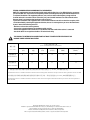
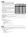
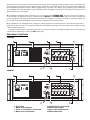
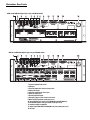
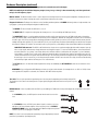
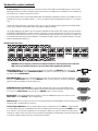
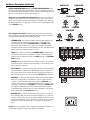
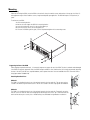
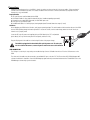
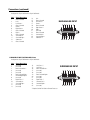
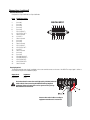
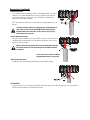
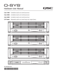
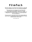
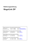
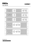
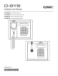
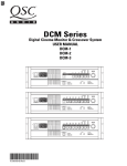
DCM Series Digital Cinema Monitor & Crossover System User Manual
DCM 10
DCM 10D
DCM 30
DCM 30D
*TD-000265-00*
TD-000265-00-A
Important Safety Instructions & Explanation of symbols
1- Read these instructions.
2- Keep these instructions.
3- Heed all warnings.
4- Follow all instructions.
5- Do not use this apparatus near water.
6- Clean only with a dry cloth.
7- Do not block any ventilation openings. Install in accordance with QSC Audio Product’s instructions. Installation
of the equipment in a rack should be such that the amount of air flow required for safe operation of the equipment
is not compromised.
8- Do not install near any heat sources such as radiators, heat registers, stoves, or other apparatus (including
amplifiers) that produce heat.
9- Do not defeat the safety purpose of the polarized or grounding-type plug. A polarized plug has two blades with
one blade wider than the other. A grounding-type plug has two blades and a third grounding prong. The wide blade
or the third prong is provided for your safety. If the provided plug does not fit your outlet, consult an electrician for
the replacement of the obsolete outlet.
10- Protect the power cord from being walked on or pinched, particularly at plugs, convenience receptacles, and
the point where they exit the apparatus.
11- Only use attachments/accessories from QSC Audio Products, Inc.
12- Use only with carts, stands, tripods, brackets, interconnecting cables, or software specified by QSC Audio
Products. When moving or transporting using a cart, use caution to avoid injury from tip-over.
13- Unplug the apparatus during lightning storms or when unused for long periods of time.
14- Refer all servicing to qualified personnel. Servicing is required when the apparatus has been damaged in any
way, such as power supply cord or plug is damaged, liquid has been spilled or objects have fallen into the apparatus, the apparatus has been exposed to rain or moisture, does not operate normally, or has been dropped.
15- When installing equipment into a rack, distribute the units evenly. Otherwise, hazardous conditions may be
created by an uneven weight distribution.
Mounting of the equipment in the rack should be such that a hazardous condition is not achieved due to uneven
mechanical loading.
16- Connect the unit only to a properly rated supply circuit.
Consideration should be given to the connection of the equipment to the supply circuit and the effect that overloading of the circuits might have on over current protection and supply wiring. Appropriate consideration of
equipment nameplate ratings should be used when addressing this concern.
17- Reliable earthing (grounding) of rack-mounted equipment should be maintained.
Particular attention should be given to supply connections other than direct connections to the branch circuit (e.g.
use of power strips).
18- Maximum operating ambient temperature is 50°C.
If installed in a closed or multi-unit rack assembly, the operating ambient temperature of the rack environment
may be greater than room ambient. Therefore, consideration should be given to installing the equipment in an environment compatible with the maximum ambient temperature (Tma) specified by the manufacturer.
The lightning flash with arrowhead symbol within an equilateral triangle is intended to alert the user to the presence of uninsulated “dangerous” voltage within the product’s enclosure that may be of sufficient magnitude to
constitute a risk of electric shock to humans.
The exclamation point within an equilateral triangle is intended to alert the user to the presence of important
operating and maintenance (servicing) instructions in this manual.
CAUTION: To reduce the risk of electric shock, do not remove the cover. No user-serviceable parts inside. Refer
servicing to qualified service personnel.
WARNING: To prevent fire or electric shock, do not expose this equipment to rain or moisture.
FEDERAL COMMUNICATIONS COMMISSION (FCC) INFORMATION
NOTE: This equipment has been tested and found to comply with the limits for a class B digital device, pursuant to
part 15 of the FCC rules. These limits are designed to provide reasonable protection against harmful interference in
a residential installation. This equipment generates, uses, and can radiate radio frequency energy and if not
installed and used in accordance to the instructions, may cause harmful interference to radio communications.
However, there is no guarantee that interference will not occur in
a particular installation. If this equipment does cause harmful interference to radio or television reception, which
can be determined by switching the equipment off and on, the user is encouraged to try to correct the interference
by one or more of the following measures:
- Reorient or relocate the receiving antenna.
- Increase the separation between the equipment and the receiver.
- Connect the equipment into an outlet on a circuit different from that to which the receiver is connected.
- Consult the dealer or an experienced radio or TV technician for help.
THIS PRODUCT IS INTENDED FOR CONNECTION TO A TN OR IT POWER SYSTEM SPECIFICALLY FOR
NORWAY POWER DISTRIBUTION SYSTEM.
有毒有害物质或元素
(Toxic or hazardous Substances and Elements )
部件名称
(Part Name)
电路板组件
铅
(Pb)
汞
(Hg)
镉
(Cd)
六价铬
(Cr(vi))
X
O
多溴联苯
(PBB)
多溴二苯醚
(PBDE)
O
O
O
O
O
O
X
O
O
O
(PCB Assemblies)
机壳装配件
(Chassis Assemblies)
O: 表明这些有毒或有害物质在部件使用的同类材料中的含量是在 SJ/T11363_2006极限的要求之下。
O: Indicates that this toxic or hazardous substance contained in all of the homogeneous materials for this part is below the limit requirement in SJ/T11363-2006.
X: 表明这些有毒或有害物质在部件使用的同类材料中至少有一种而含量是在SJ/T11363_2006极限的要求之上。
X: Indicates that this toxic or hazardous substance contained in at least one of the homogeneous materials used for this part is above the limit requirement in
SJ/T11363-2006.
© Copyright 2007 QSC Audio Products, Inc. All rights reserved.
QSC® is a registered trademark of QSC Audio Products, Inc., DCM Manager is a trademark of QSC Audio Products, Inc.
“QSC” and the QSC logo are registered with the U.S. Patent and Trademark Office.
Windows and Windows XP, 2000, and VISTA are trademarks of Microsoft Corporation.
IBM is a registered trademark of IBM Corporation; Pentium is a registered trademark of Intel Corporation.
Introduction
Thank you and congratulations on your purchase of the QSC DCM Digital Cinema Monitor. This product represents the state-of-the-art for cinema-based
signal processing and monitoring functions in a single, integrated system.
Designed to compliment QSC’s DCA (Digital Cinema Amplifier) Series and DCS
(Digital Cinema Speaker) Series products, the DCM optimizes loudspeaker performance while facilitating easy cinema sound system wiring and configuration. To get the most from your investment, we encourage you to review this
manual carefully.
The QSC DCM provides a wealth of signal processing functions with the ability
to copy and transfer settings—resulting in fast system setup time in multiplex
theaters where multiple rooms share similar characteristics. Providing both
monitor and crossover functions in a single unit, the DCM is capable of simple
crossover adjustments via a personal computer (PC). These modifications can
be password protected for tamper-proof system control.
Fast Setup with Easy Wiring
Your DCM takes advantage of the unique DataPort found on DCA Series amplifiers and thus greatly simplifies system wiring—reducing installation and labor
costs in the process. A single VGA-style cable per amplifier channel pair contains two input signals, two return signals, power on/standby control, and two
channels of load monitoring.
Table 1: Supported Formats By Model
Format
DCM 10
DCM 10D
DCM 30
DCM 30D
6 Channel Passive
Yes
No
6 Channel Bi-Amp
Yes
Yes
6 Channel Tri-Amp
No
Yes
6 Channel Quad-Amp
No
Yes
8 Channel Bi-Amp
No
Yes
8 Channel Tri-Amp
No
Yes
8 Channel Quad-Amp
No
Yes
Surround-EX
Yes
Yes
The included PC configuration software further enhances the DCM setup. This software includes a database that lists the default parameters for popular cinema loudspeaker models. Commonly used configurations can be saved to disk, facilitating the easy transfer of settings to other DCMs.
Advanced Monitoring Control
In addition to the monitoring of your amplifier’s audio I/O, your DCM includes QSC’s exclusive “Load Fault” detection feature. The DCM monitors for
possible loudspeaker system or wiring faults and notifies you via LED Load Fault indicators.
System Requirements
DCM Manager software is designed to control one DCM hardware unit at a time. To use this software with the DCM hardware unit, you must have
the following:
1- Digital Cinema Monitor unit
2- DCM Manager 2007 software installation CD
3- IBM-compatible PC with a 1 GHz Pentium 4 processor (or better)
Windows XP or VISTA operating system
Microsoft® Internet Explorer
Minimum of 512 MB of RAM
Minimum of 500 MB of available hard disk storage space
CD-ROM drive
Display resolution of 1024 x 768, 16 colors minimum
USB port
To complete your Cinema System, you will also need a cinema processor, QSC Audio’s DCA amplifiers, loudspeakers, and necessary cables.
Unpacking
The DCM is highly durable and carefully packaged. We recommend you inspect the unit carefully after removing it from the packaging, as occasionally there may be damage due to some unfortunate incident during shipment. Report any damage to the shipping carrier. We recommend saving the
carton and packing material in case the unit must be shipped back to your dealer, distributor, or service center. Also note: some freight companies
consider damage claims without the original packing materials invalid.
The QSC shipping box should contain:
1- the DCM unit
2- this owner’s manual
3- AC power cord, IEC-type, 18 AWG, 6 feet long, 120V
4- warranty card
5- DCM Manager Application Disk
System Concepts
Installer Features:
•Provides Monitor and Crossover functions in one box.
•Minimizes the amount of cabling required. Only 1 cable per amplifier channel pair.
•Minimizes setup time, particularly in megaplexs with similar rooms.
•Provides loudspeaker setting database for most common theater loudspeaker brands and models.
•Indicates if something is wrong with the sound system and provides diagnostic feedback.
•Emergency bypass allows center channel sound to pass through even if there is a major problem.
•Allows easy routing and crossover adjustments.
•Protects system adjustments from tampering.
•Sound quality is state-of-the-art (high dynamic range).
Projectionist Features:
•Easy to verify all of the audio in the theater is okay.
•Automatic monitoring will light an LED if there is trouble with a loudspeaker output.
•A backup system (emergency bypass) can be easily activated.
1. QSC Amplifier DataPorts- The DataPort connectors reduce the complexity of wiring between the DCM and the amplifiers. The DataPort connections
replace amplifier audio input cables and amplifier output monitor connections. Another unique feature of the QSC Cinema System is the ability to
automatically analyze voltage and current on the amplifier’s output terminals to determine shorts or opens in the loudspeaker cables or drivers. Each
amplifier channel pair is connected using one DataPort cable. We recommend you use QSC DataPort cables. Normal computer VGA cables often do
not have all pins terminated. QSC’s DataPort cables feature high quality shielded audio wires within the cable for maximum interference protection
on long runs or for electrically-noisy environments.
2. Programmable processing and crossover settings- DCM processing is adjusted using the DCM Manager software and the USB connection. Configuration files can be saved and used for other DCMs. For example, if a megaplex theater has several rooms with similar size and equipment, a technician can adjust one DCM unit for best results, and then download all of these settings to other DCM units. The functions that can be controlled
remotely are: crossover settings for screen channel outputs, mutes, multiple equalizer settings per channel, delay times, output volume levels, monitor mix balance adjustments, and more.
3. DSP processing- Digital filtering of audio signals is known to have several advantages over analog solutions. DSP (digital signal processor) IC chips
allow extremely accurate and reliable control of frequency and time adjustments (boost, cut, cutoff frequency, delay time), and stability (immunity
from temperature variations). The audio path of the DCM uses conversion circuitry (changing the signal from analog to digital and back again) which
is designed to minimize all background noise and react to the dynamic range of any film track.
4. Loudspeaker Database (pre-programmed settings)- QSC has worked with the leading suppliers of theater loudspeakers to obtain the optimum settings for most common theater loudspeaker models. This database is easily loaded into the DCM hardware unit and the DCM Manager software
offers features to organize, store, and edit these settings. This feature guarantees that your installation starts with technically optimized settings
before you begin adjusting for room characteristics.
5. Fault Analysis- Each amplifier output channel is compared to the corresponding input signal providing complete signal path confirmation. For example, if there is signal at the DCM output but there is no signal at the corresponding amplifier output, then the fault indicator will light. Additionally, if
an amplifier output is shorted or open, the fault indicator will light. By pressing and holding down the Amps/Proc button, the DCM’s front panel LEDs
will indicate which channel has the fault condition. Detailed fault information can also be viewed using the DCM Manager software.
6. Password Security- The crossover settings that you create can make a dramatic difference in the sound quality within the theater. Many installers
pride themselves on being able to adjust the electrical parameters (crossover points, equalization, delay, etc) to exactly compliment the loudspeaker
and room interactions. As such, their ability to set these parameters is a “value added” service which deserves protection from competitors. We have
therefore included a security system where you can protect your settings within the DCM from being uploaded and copied by the DCM Manager software. Only your unique password will allow viewing or editing of the crossover settings. Should you forget your password, an entirely new configuration can be loaded.
7. Emergency Bypass- If the DCM fails, quickly getting a usable sound path is as easy as flipping a switch. An active crossover has been built into the
center channel routing so that a usable sound path will be maintained, even when using the digital inputs. To put the DCM into emergency bypass,
set the front panel BYPASS switch to the BYPASS position.
8. Auxiliary Input- The auxiliary input is an analog input that may be used to drive an additional loudspeaker channel in the auditorium. Monitoring of
this channel is available via the front panel “Aux” selector switch. The amplifier output is via a single DataPort connection that may be configured as
two full range channels or one bi-amplified channel. Typical applications include ceiling surround channels or public address loudspeakers. The output may also be configured as an additional surround, surround subwoofer, or backwall output.
9. Alternate EQ Select- Connecting this terminal to ground with an external switch or relay contact enables an alternate setting of each channel’s parametric equalization. The alternate settings are made at the time of installation by using the DCM software. This allows for an alternate equalization to
be quickly enabled during alternative content or advertising playback. Many “non-feature” film soundtracks are not recorded to X-Curve standards and
often sound bright or harsh when played back in a theatre calibrated for feature film playback. The front panel ALT EQ indicator LED illuminates when the
alternate equalization has been enabled.
10. External Monitor Loudspeaker- On the rear panel are a set of screw terminals marked EXTERNAL SPKR. These are for connection to an external
monitor loudspeaker. As shipped from the factory, a jumper between the IN SPR and the EXTERNAL SPKR + terminal routes audio to the DCM’s internal monitor loudspeaker. This jumper must be removed if an external monitor loudspeaker is used, otherwise the DCM’s internal monitor amplifier will
be overloaded. The minimum load impedance of the external monitor loudspeaker must be 4 ohms or greater.
11. Bass Management- Bass management allows extremely low frequency program content to be filtered from the screen channels and rerouted for
mixing with the subwoofer output. This can reduce the amplification and loudspeaker requirements for all screen channels while minimally increasing
subwoofer capability requirements.
A separate surround channel bass management feature allows the extremely low frequency surround channel program content to be filtered from the
surround channels and summed for routing to the AUX DataPort output.
Illustrations- Front Panels
DCM 10/10D
DCM30/30D
1- Power switch
2- Monitor output loudspeaker
3- Power “on” and diagnostics indicator LEDs
4- Monitor source selector buttons
5- Amplifier/Processor selector button
6- Monitor output test points
7- Bypass switch and indicator LED
8- Monitor volume control
Illustrations- Rear Panels
DCM 10 and DCM 10D (Digital Inputs only on DCM 10D model)
DCM 30 and DCM 30D (Digital Inputs only on DCM 30D model)
1- Firmware update mode select
2- USB port
3- External loudpseaker connector and select
4- Subwoofer output
5- Alternate equalization select input
6- Auxiliary audio input
7- Hearing impaired output
8- Emergency bypass level controls and switch
9- Main analog input (from cinema processor)
10- Analog/digital input select switch (DCM 10D and DCM 30D only)
11-Surround EX (option card) input (from cinema processor)
12- DataPort outputs to amplifiers
13- Digital input (DCM 10D and DCM 30D only, from cinema processor)
14- IEC inlet
Hardware Description
Front Panel
The front panel of the DCM series resembles traditional cinema monitor products. This provides the projectionist a
well known and easy to understand interface.
Power Switch: The power on/off switch is the master control for the DCM and the amplifiers connected to it.
Amplifiers must be connected to the DCM with QSC DataPort cables and amplifier power switches must physically
be in the “on” position. The DataPort connection to DCA amplifiers have a standby control pin which provides
standby control. QSC’s DCA amplifiers feature zero inrush current, requiring no additional start-up sequencing.
Amplifier standby power control can be bypassed using the BYPASS switch, see settings, below.
The Emergency Bypass switch setting alters the Power Status of the
amplifiers.
BYPASS switch set to NORMAL: The Power Status of all amplifiers connected
to the DCM DataPorts will respond to the DCM power switch. When the switch
is in the ON position, all the amplifiers will be on. When the switch is in the off
position, all the amplifiers will be in Standby mode.
BYPASS switch set to BYPASS: Amplifiers connected to the DCM DataPorts
will remain on even if the DCM Power switch is set to the off position.
Monitor Output Loudspeaker: The front panel loudspeaker provides direct monitoring of the processor and
amplifier output audio signals. The Processor/Amps and Monitor source selection buttons determine what is being
monitored and the Monitoring Volume control determines the loudspeaker’s output level.
The front panel TEST connections provide the same signal used to drive the Monitor Loudspeaker prior to the monitor loudspeaker equalization and gain potentiometer (pre-fader). TEST
signal levels are the same level as the cinema processor output signals (unity gain) and can be
used for system calibration.
AMPS/PROC Selector Button: The AMPS/PROC button determines the function of the Monitoring Select buttons, to the right of the AMPS/PROC button. The LEDs directly over the AMPS/PROC button indicate what
selected function the Monitor Select buttons will have. When the PROC LED is illuminated, the Monitor Select buttons will select or deselect the various Cinema Processor inputs to the DCM for monitoring. When the AMPS LED is
illuminated, the Monitor Select buttons select or deselect amplifier outputs for monitoring. After the AMPS/PROC
choice has been made, the individual channel buttons determine exactly which signals are routed to the front panel
monitor loudspeaker.
Monitor Source Selection Buttons: Pressing any of the Monitor Select buttons will either select or deselect the
corresponding signal for monitoring. Each button can select either the Processor signals (input to the DCM) or the
Amplifier signals (output to the amplifiers), depending on the current selection of the AMPS/PROC button. By
using the DCM Manager Monitor Settings page, any of the DataPort Vmon signals (amplifier output to loudspeaker)
can be soloed to the monitor. LEDs provide confirmation of the active monitor source for each of the cinema channels. The DCM makes monitoring simple. Select the AMPS or PROC function and then select the desired L, LE, C,
RE, R, SB, SL, SR, BSL, BSR or AUX channel.
The DCM 30 and DCM 30D provide 2 surround left (SL) and surround right (SR) DataPorts for side wall channels, as
well as 2 back surround left (BSL) and 2 back surround right (BSR) for back wall channels. These can create two
distinct “zones” where volume controls can be adjusted. One typical installation would be to connect the SL1 and
SR1 signals to the loudspeakers closest to the screen, SL2 and SR2 in the next set of loudspeakers further away
from the screen. Other installations might require loudspeaker sets where some loudspeakers are along the theater
side walls while other loudspeakers are under a balcony overhang. By connecting these loudspeakers as “zones”,
the sound levels will be much easier to balance. The DCM 30 and DCM 30D also have 8 subwoofer outputs.
Hardware Description (continued)
NOTE: The DCM 10 and DCM 10D have one output for each surround zone and 4 sub outputs.
NOTE: All combining of the individual frequency outputs (2-way, 3-way, or 4-way) is done automatically, so all front panel monitoring is of a full frequency signal.
Monitor Volume: The Monitor Volume control is used to adjust the monitoring volume from the front panel loudspeaker. Rotating the control
clockwise increases the volume. Rotating the control counter-clockwise decreases the volume.
Diagnostic Indicators: The diagnostics indicator section (including and directly below the POWER indicator) provides a simple method of verifying proper system operation and performing basic troubleshooting.
The POWER LED shows whether the DCM unit is on or off.
The INPUT CLIP LED is helpful in verifying that the cinema processor is not over-driving the DCM input circuitry.
The LOAD FAULT indicator is a unique and powerful feature which verifies that signal inputs into the DCM actually make it through the
DCM, the DataPort cables, and the amplifier unit all the way to the loudspeakers, and that the loudspeaker connections are not electrically
shorted or open. All of these measurements are being performed constantly (without user action) on ALL output channels and any unusual
readings will light the Load Fault LED. If the Load Fault LED is lit, pressing the Amps/Proc button (and holding it pressed) will cause the problem channel’s indicator LED to blink. This information will let you inspect the system cabling for that channel and troubleshoot the problem.
LOAD FAULT indicator note: The DCM’s Load Fault detection scheme uses a complex averaging algorithm which compares input signals to output signals and measures voltage and current on all amplifier outputs. To sense real world conditions, these measurements
must be found to be “out of range” several times before the Load Fault condition is indicated on the front panel. If you are simulating
fault conditions, you MUST have a “real-world” signal level through the device (full signal input), and the fault condition must exist for
several minutes before the front panel Load Fault LED will light. This extra fault verification time eliminates false triggering which would
be confusing to a user. In conclusion, just shorting the output terminals will NOT cause the fault LED to light, the unit must be driven by
real-world input signals and the fault must persist for several minutes.
The ALT EQ indicator is lit when the alternate equalization settings are enabled by the ALT EQ SELECT contact closure terminals on the
rear panel.
REMEMBER: If you configured the DCM Manager software to not have certain channels (for example there is no SUB 3 or SUB 4) or have
not assigned a QSC amplifier to a channel, these channels WILL NOT indicate any faults.
Test Jacks: The test jacks provide the signal being sent to the front panel loudspeaker (pre-level adjust and pre-EQ).
The signal level is the same as the cinema processor output signal (unity gain) and can be used as a test point for system
calibration.
BYPASS Switch: If there’s a problem with the DCM or system cabling, the DCM active circuitry can be bypassed, routing audio to the center
channel.
In the NORMAL position, the DCM performs normal monitor and crossover functions.
In the BYPASS position, the PROC center channel signal is routed to a crossover,
and then to the center channel amplifier. On the rear panel, there is a BYPASS
CROSSOVER MODE select switch and equalization band level adjustment potentiometers for precisely setting bypass mode audio.
NOTE: The switch is recessed and can be operated by using an appropriately sized tool
(small flat tip screwdriver, tip of ballpoint pen).
Hardware Description (continued)
Rear Panel
Amplifier DataPorts: Each DataPort provides two channels of audio from the DCM to the QSC amplifier input, as well as current
and voltage monitoring of the amp’s loudspeaker outputs. Remote power on/standby control of the amplifier is also provided, allowing the DCM to act as a master system power controller.
Use only QSC DataPort cables. Custom-length DataPort cables with individually shielded-pair construction are available from QSC’s
Technical Services Group. Stock lengths include 1, 2, 3, 4, 5, 6, 10, and 20 feet and are designated DPC-x (where “x” is the length in
feet).
The maximum output configuration of the DCM 10/10D is a 6 ch / 2-way. The maximum output configuration of the DCM 30/30D is
an 8 ch / 4-way. In addition, many parallel outputs are provided for additional flexibility.
The rear panel labelling on the DCM has all of the information required by an audio installer. When starting, write down the EXACT
LOUDSPEAKER CONFIGURATION (for example, 8 channel, tri-amp with 2 surrounds and 4 subs). Now you can follow the rear panel
text which shows both channel position (L or C or R, etc) and the frequency output (LO, MID, HI, etc). Connect the L-LO output to the
correct amplifier driving the left positional loudspeaker’s low frequency transducer, and L-HI to the amplifier driving the same loudspeaker’s high frequency transducer, etc.
DCM 30 DataPort Illustration:
WARNING: Incorrect frequency connections can damage transducers. Physically verify proper connections
AND listen to each individual transducer at very low volume before applying full audio power.
INPUT SELECT Switch: Use this switch to select the input source of the DCM. In the ANALOG position, input is from
the MAIN ANALOG INPUT ( and the SURROUND EX INPUT, if this option is installed). If the switch is in the DIGITAL position, input is from the DIGITAL INPUT.
MAIN ANALOG INPUT: Connect this to the cinema processor’s output. This is the input source of all film sound into the
DCM unit if the INPUT SELECT switch is set to the ANALOG position. The 25-pin connector is an industry standard type
and pinout; cables are available from cinema supply houses.
SURROUND EX INPUT (OPTION CARD): This input provides additional inputs when using a Dolby CP650 with the
Cat.790 or Cat.791 option cards. The surround, backwall surround, and left extra/right extra channels are input through
this connector. The INPUT SELECT switch must be set to ANALOG in order to use this connection.
DIGITAL INPUT: If using a Dolby CP650 with Cat.778 option, connect the CP650 digital output to this connector. Set the
INPUT SELECT switch to DIGITAL to select the digital input.
USB Connection: Connect to USB port on the host PC. Communication between the DCM Manager software (running on the host
PC) and the DCM is routed throught this connection.
Firmware Update Mode Select: This recessed push button switch is located directly left of the USB port. To place the DCM
in firmware update mode, press inward and hold the switch in the depressed position while turning the AC POWER switch on.
Use a small tool, such as the end of a paperclip wire or similar object to depress the switch. The AC power must be off before
initiating this sequence. Release the switch once the AC power has been applied. The DCM Manger software may then be used
to continue the update procedure (refer to the software help file for details).
Hardware Description (continued)
DCM 10/10D
DCM 30/30D
BYPASS CROSSOVER MODE Switch: The BYPASS CROSSOVER MODE switch
routes the center channel input signal through the 2-way or 3-way bypass crossover on
the DCM 30/30D. On the DCM 10/10D, the center channel is routed through the 2-way
bypass crossover or not processed at all (passive bypass).
Bypass Crossover Level Adjustment Potentiometers: These are used to adjust the
characteristic of the Bypass crossover. The frequency-specific levels of the crossover
outputs from the DCM to the center channel amplifiers can be adjusted to suit the center channel loudspeakers. This signal path is only active if the front panel bypass switch
is in the BYPASS position.
DCM 10/10D
DCM 30/30D
Barrier Strip Screw Terminals: The barrier strip screw terminals provide connections for output to an external monitor loudspeaker, subwoofer, alternate equalization
switching, auxiliary input, and hearing impaired audio output.
EXTERNAL SPKR: These terminals provide the identical audio supplied to the
front panel’s monitor loudspeaker. If using an external monitor loudspeaker,
remover the jumper between the EXTERNAL SPKR + and IN SPR terminals.
Removing this jumper disables the internal monitor loudspeaker. Any external
loudspeaker used must have a minimum impedance of 4 ohms. The DCM’s internal
monitor amplifier has a maximum output of 15 watts.
IN SPR: This terminal is connected to the EXTERNAL SPKR + terminal if using
only the DCM’s internal monitor loudspeaker. If using an external monitor loudspeaker, remove the jumper that connects the IN SPR terminal to the EXTERNAL
SPKR + terminal.
SUB OUT provides the identical audio as the subwoofer DataPort. This connection
cannot be monitored or include any of the Fault Analysis functions because there
are no signal return connections.
ALT EQ SELECT is a contact closure input used to activate an alternate equalization which has been created using the DCM Manager sofware. A switch or set of
relay contacts may be used to activate/deactivate the alternate equalization settings. When the contacts are closed, the front panel ALT EQ indicator illuminates.
AUX INPUT is a single mono audio input that can be used to supply an additional
channel for a ceiling speaker or other application. The aux channel can be processed as a 1-way channel and output to both channels of DataPort O or processed as a 2-way output , with low band and high band going to channels 1 and 2
of DataPort O, respectively. If the Aux INPUT is not being used, DataPort O can
be assigned as an additional Left Surround/ Right Surround Output, Back Left
Surround/Back Right Surround Output, or as a bass-managed mix of all surround
channels (duplicated to both DataPort O channels).
HEAR IMP OUT is a single mono audio output which contains a mix of the left,
center, and right signals with the center signal boosted 6 dB. This is usually connected to a special cinema system which supplies headphone audio feeds for people with hearing difficulties. This can also be used as an input signal to a powered
loudspeaker for remote monitoring of basic L/C/R signals in larger projection
booths.
IEC Inlet: The power receptacle accepts a standard IEC power cable. The DCM uses a
switching power supply that accepts 100 to 240 volts AC, 47-440 Hz.
Mounting
Rack Mounting
When rack mounting the DCM, secure the DCM to the rack rails using four machine screws and washers of the proper size. Most US
rack equipment accepts #10-32 machines screws; length used depends upon application. The DCM will require 3-RU (rack units) of
space.
To rack mount your DCM:
1- select mounting location
2- have an assistant support the DCM in its mounting location
3- secure the two bottom screws first; do not fully tighten yet
4- secure the top two screws, do not fully tighten yet
5- “fine tune” the DCM up, down, right, or left as required and tighten the four mounting screws
Supporting the Rear of the DCM
When shipping completed sound racks, it is extremely important to support the rear of the DCM. The chassis and rack can be damaged
if the DCM is not properly supported. Unless the DCM is being installed in its final, fixed location, QSC strongly recommends supporting
the rear of the unit. Rear rack ears, required hardware, and a separate instruction sheet are available from QSC’s Technical Services
Group (part number FG-000031-00).
Attaching Rear Rack Ears:
Method 1
The DCM is first installed from the front of the rack and secured to the front rack rails. The rear ears are then
secured to the DCM using two machine screws. The ears are secured to the rails using regular rack hardware.
Method 2
The DCM is first installed from the front of the rack and secured to the front rack rails. Temporarily secure the
rear ears to the rear rack rails and select the appropriate mounting position for the “pin”. Remove the rear ears
and install the locator pins securely. Use of thread-locking is recommended for high-vibration installations.
Software Description
DCM Manager Windows Software
To access the functions of the DCM hardware, you must use QSC’s DCM Manager 2007 control software. A USB cable is used to connect
your PC to the DCM. One of the computer’s available USB ports provides communications between the DCM Manager software and the
DCM hardware. The PC must meet the minimum System Requirements as outlined in the Introduction section of this manual. The USB
cable should be no longer than 5 meters. For longer distances, USB hubs, USB line extenders, or active USB extension cables must be
used.
A typical cinema installation should require this setup procedure ONLY during the initial installation of the system. One particular advantage of the DCM Manager software and DCM hardware is the ability to calibrate one DCM-based cinema system and easily download
ALL of these settings to any number of additional DCM units in venues that are similarly equipped.
To aid in calibrating the crossover settings, the DCM Manager control software includes a database including many well known cinema
loudspeakers. This data will automatically set the DSP filters and transducer alignment delay settings within the DCM hardware according to the settings recommended by the loudspeaker manufacturer for optimum sound performance. Select loudspeakers for each of the
physical locations (L,C,R, SL, SR, SUB), and a large portion of the system calibration is finished!
After loudspeakers have been selected in the DCM Manager software, processing parameters can be adjusted real-time. When settings
are complete, the software can save the settings to the DCM hardware’s flash memory and the DCM hardware can be disconnected from
the host PC.
NOTE: QSC updates these files regularly as new models are introduced from loudspeaker manufacturers or settings are improved. Visit our
website http//:www.qscaudio.com for the latest cinema products information and technical support.
Software Installation
1- Start the PC.
2- Exit any programs that may be running.
3- Insert the QSC DCM Manager 2007 CD in the CD-ROM drive and close the drive.
4- The installation routine will automatically start. Follow the instructions on screen.
5- If the install does not automatically start, select Run from the Windows Start menu, specify the appropriate drive and select setup.exe;
the installation routine will start.
6- Windows VISTA only- If a message indicating the program did not install correctly is displayed, select “Reinstall Using Recommended
Settings”.
Starting the Program
1- Connect the USB cable between the host PC and the DCM hardware. When connecting for the first time, the Found New Harware wizard will be displayed.
Windows XP:
On the first screen, select “No, not at this time” and click “Next”. On the next screen, the default selection “Allow Windows
to select a driver” will be highlighted; click “Next”. If a warning stating the driver is not signed appears, you may safety select
“Continue.” The driver will then be installed.
Windows Vista:
On the “Found New Hardware” window, select ‘Locate and install driver software (recommended).’
If a Windows Security message appears, Select ‘Install this driver anyway.’ The driver will then be installed.
2- The DCM Manager program can be launched using the Windows Start/Programs selection.
Using the DCM Manager Software
After launching the DCM Manager program, click on the Help menu item for a full-featured software help system.
Connections
Making the required connections to the DCM is simple. Just make sure that you have all of the correct cables. “Mass-termination”
connectors are used wherever possible. This reduces installation time from hours to minutes and makes any required connection
changes fast, easy, and reliable.
Required Cables
1- IEC-style AC power cord (included with the DCM)
2- QSC DataPort cable for every amplifier channel pair (8 to 19 cables depending upon model)
3- Cinema Processor cable (DB25 male-male) for each DB25 input used.
4- USB Type A to Type B device cable.
5- Shielded audio cables for Auxiliary Input, Hearing Impaired, and Powered Subwoofer outputs (if used)
AC Mains
Before plugging your DCM into the AC mains, verify proper operating voltage. The serial number sticker located on the rear of the DCM
has the rated operating voltage information printed on it. Locate the sticker, note the rated voltage, and ensure the AC circuit you
intend to use is properly rated.
Locate the IEC-style AC power cord supplied with your DCM. Identify the “IEC” end (molded
plastic block), line it up with the rear panel IEC receptacle, and insert it fully.
Plug the AC plug end of the cable into a functioning AC outlet of the proper voltage.
The DCM is equipped with a detachable IEC-style AC power cord. To reduce the
risk of accidental disconnect, secure all power cords in the course of installation.
USB CONNECTION
The USB port is used only for setup and system troubleshooting. Connect USB cable from the host PC to the USB connector on the
DCM.
The other end of the cable must be connected to an available USB port on the host PC. The PC must have QSC’s DCM Manager 2007
software installed on its hard drive. Start the DCM Manger program and verify communication between the PC and DCM. Refer to the
DCM Manager software help system for details.
Connections (continued)
DataPort
The QSC DataPort connection carries input signals, amplifier
output monitoring signals, remote amplifier power on/
standby control, amplifier temperature, and more, all on one
cable. Each DataPort is clearly marked indicating which
channel’s amplifier it should be connected to. Follow the
back panel labelling. Connect each DataPort to its respective
amplifier’s DataPort. Finger-tighten the retaining screws on
the cable connectors; do not overtighten!
Connect a DataPort cable from each of the DCM’s DataPorts
to each of the system’s DCA amplifiers.
Orient the cable’s HD15 male connector properly and push
the connector onto the DCA’s receptacle. Finger-tighten the
retaining screws to ensure reliable connection. Connect the
other end of the cable to the DataPort on the corresponding
channel’s DCA amplifier.
DataPort Pinout
Configuration: 15-pin SubD (high-density) male to 15-pin
SubD (high-density) male.
Pin #
1
2
3
4
5
6
7
8
9
10
11
12
13
14
15
Signal Description
Ch. 1 Minus (-) Signal
AC Standby Control
V- MON Ch. 1 and Subcode 1
I- MON Ch. 1 and Subcode 2
Clip/Protect Ch. 1
Hard Ground
Ch. 1 Plus (+) Signal
Ch. 2 Plus (+) Signal
+15V from Amplifier
Data Reference Ground
Ch. 2 Minus (-) Signal
Amplifier IDR (Model ID)
V- MON Ch. 2 and Subcode 3
I- MON Ch. 2 and Subcode 4
Clip/Protect Ch. 2
Use QSC DataPort cables. Contact QSC’s Technical Services Group if you would like to purchase standard length
DataPort cables or specially made custom length cables that use shielded audio-pairs for the best possible performance.
Cinema Processor Connection
Audio signals are input to the DCM via the Main Analog Input, Surround EX Input or Digital Input connections. These DB25-type connections conform to cinema industry standard pinout. Most common cinema processors use this DB25 connection standard, making connection to the DCM simple. Orient the DB25-type connector properly, push gently to seat the pins, then finger-tighten the retaining screws.
Cinema processors that do not use standard DB25-type connection typically have adapter cables available. Check with the processor
manufacturer. We recommended that you purchase a standard 25-pin cable from any of the well known cinema industry cable suppliers.
Connections (continued)
MAIN ANALOG INPUT Pinout
Configuration: 25-pin SubD male to 25-pin SubD male.
Pin #
1
2
3
4
5
6
7
8
9
10
11
12
13
Signal Description
Chassis Ground
Left +
Left Center Chassis Ground
Center +
Right Center Chassis Ground
Right +
Chassis Ground
Surround Left Surround Right Subwoofer Chassis Ground
14
15
16
17
18
19
20
21
22
23
24
25
Left Chassis Ground
Left Center +
Center Chassis Ground
Right Center +
Right (not used)
Chassis Ground
Surround Left +
Surround Right +
Subwoofer +
MAIN ANALOG INPUT
SURROUND EX INPUT (OPTION CARD) Pinout
Configuration: 25-pin SubD male to 25-pin SubD male.
Pin #
1
2
3
4
5
6
7
8
9
10
11
12
13
Signal Description
(not used)
(not used)
Back Surround Left (not used)
(not used)
Back Surround Right Ground Digital Inputs
(not used)
Right Extra + *
Surround Left Surround Right (not used)
(not used)
14
15
16
17
18
19
20
21
22
23
24
25
Left Extra + *
Left Extra - *
Back Surround Left +
(not used)
(not used)
Back Surround Right +
(not used)
(not used)
Right Extra - *
Surround Left +
Surround Right +
(not used)
* Requires Cat.No 791 Card on Cinema Processor
SURROUND EX INPUT
Connections (continued)
DIGITAL INPUT Pinout
Configuration: 25-pin SubD male to 25-pin SubD male.
Pin #
1
2
3
4
5
6
7
8
9
10
11
12
13
14
15
16
17
18
19
20
21
22
23
24
25
Signal Description
(not used)
(not used)
(not used)
(not used)
(not used)
(not used)
AES1 (L/R) OUT +
AES3 (Ls/Rs) OUT +
Chassis Ground
X1/2 OUT +
Chassis Ground
(not used)
(not used)
Chassis Ground
AES1 (L/R) OUT AES3 (Ls/Rs) OUT X1/2 OUT Chassis Ground
(not used)
(not used)
AES4 (Bsl/Bsr) OUT AES4 (Bsl/Bsr) OUT +
AES2 (C/SW) OUT AES2 (C/SW) OUT +
Chassis Ground
DIGITAL INPUT
Hearing Impaired
The Hearing Impaired output signal is available on the screw terminal connector on the rear of the DCM. The output signal is similar to
levels that are output from a standard CD player.
Output Level
-11.8 dBu
(200 mVrms)
Impedance
50 ohms
(±5%)
Use balanced audio connections and high-quality, shielded, balanced
audio cable for interconnecting the DCM and Hearing Impaired
equipment. Balanced connections are less prone to noise pick-up
than unbalanced connections.
Connect other end of cable according to
equipment manufacturer’s instructions.
Connections (continued)
Powered Subwoofer
Screw terminal connections make it possible to send a balanced signal to a powered
subwoofer. This signal is balanced and the circuitry is designed for long cable runs
from the projection booth to the theater screen. The high-pass filtering and level
adjustments are done by the DCM unit.
NOTE: There will be no fault analysis or output audio monitoring available for this sub
channel.
Use balanced audio connections and high-quality, shielded, balanced
audio cable for interconnecting the DCM and Powered Subwoofer
equipment. Balanced connections are less prone to noise pick-up
than unbalanced connections.
External Speaker Connection
The monitor signal is available on the screw terminals at the rear of the DCM. This powered signal can be connected directly to an external 8-4 ohm speaker such as the QSC
AD-S52 for remote monitoring.
When using an external speaker, the factory-installed jumper powering
the internal speaker must be removed to prevent overload of the monitor amplifier.
Connect other end of cable according to
equipment manufacturer’s instructions.
Auxiliary Input Connection
An additional input channel may be included through the AUX INPUT terminals.
ALT EQ SELECT
Closing a switch across these terminal inputs enables an alternate setting of each channel’s parametric EQ. A front panel LED
indicates when the alternate EQ setting has been selected.
System Calibration
When installing a typical cinema sound system, most of the calibration involves the Cinema Processor. Refer to the user manual for the
Cinema Processor that you are using.
WARNING: Turn the Gain Controls on all of the system’s amplifiers all the way down until crossover settings and
levels are verified!
Connect a PC computer to the USB connector, turn on the DCM unit, start the DCM Manager 2007 software and download a
configuration file that corresponds to the equipment installed in the theater.
Once all system and crossover settings are correct in the DCM Manager software, you are ready to start calibration.
1. Theater - audio level adjustments
The combination of QSC amplifiers and loudspeakers contained in the DCM Manager database will require little or no DCM adjustment. Transducer sensitivity imbalances within the loudspeakers have been compensated for by the factory recommended crossover
settings. However different amplifier configurations may require gain adjustments to achieve the flattest frequency response. Proper
adjustment of the crossover gain settings should be verified before any EQ adjustment is made. If you are using a powered subwoofer,
or a loudspeaker not contained in the factory supplied loudspeaker database, you may need to make level adjustments.
2. Bypass Levels
When the bypass button on the front panel of the DCM unit is activated, a crossover is used to divide the center channel audio signal
into either a 2-way signal (high frequency and low frequency), or a 3-way signal (DCM 30/30D only). The relative volumes of these signals can be adjusted on the rear panel of the DCM unit. Feed pink noise into the center channel input, compare the center channel
sound while the front panel button is in the Normal position to the sound while in the Bypass position. While in the bypassed position,
adjust the potentiometers to most closely match the normal position sound.
DCM 10/10D
3. Monitoring - audio mix adjustments
The DCM Manager software allows balancing of the high/low or high/mid/low signals being fed to
the front panel monitor loudspeaker. Input pink noise into all of the DCM input channels and select
individual channels using the DCM front panel buttons.
Select the surround channels first to make a reference level. Now select other channels one at a
time and balance these gain settings for a sound level similar to the surround channels.
4. Loudspeaker Frequency adjustments
The manufacturer of any loudspeaker will be able to supply you with recommended
crossover settings. The settings for most commonly available cinema loudspeakers are
included in the DCM Manager speaker database. By simply assigning the correct
loudspeaker make and model to each channel, the majority of loudspeaker EQ
adjustment is complete. The DCM offers additional filters (high pass, parametric EQ, screen EQ, and
Horn EQ), driver and channel delay, polarity, and gain adjustments which can be used as additional
compensation for loudspeaker and installation characteristics.
DCM 30/30D
WARNING: Inappropriate crossover settings can damage loudspeakers!
5. Setting Delay Times
Driver delay settings compensate for the physical displacement between transducer centers within one loudspeaker. Consult the loudspeaker manufacturer for help in determining this setting. Channel delay compensates for the distance that a loudspeaker is located
from the screen. We have included some screen delay adjustment, but most typical theaters will not need to use this because surround
channels are delayed coming from the cinema processor. Consult an acoustic consultant for the proper calibration method, or experiment until the sound from the screen together with sound from the surround loudspeakers sounds more “clear”.
Troubleshooting
If the DCM Manager program is unable to communicate with the DCM hardware...
• Verify the USB cable connections. Re-seat each cable-end.
• Try a known-good USB cable, if possible.
• Confirm the USB port you are using is operating properly. Windows has provisions for checking hardware in the Windows Control
Panel. Refer to the Windows help system for more information.
• Cycle the power of both the PC and the DCM.
If there is no audio from the front panel Monitor Loudspeaker....
• Check the Monitor Volume control; it should be set to a useful level, not fully counter clockwise.
• Verify the desired active monitor source is selected by pressing the AMPS/PROC selector button and observing the illuminated LEDs
above channels selected for monitoring. Select or deselect your desired monitor sources.
• Try just selecting the center channel of the Cinema Processor input (select PROC, then select C using the front panel push-button controls). If there is a center channel input signal connected to the selected input (Main if analog selected, Digital if digital selected) connector on the rear of the DCM, it should be audible now. If not, continue with the next step.
• Verify the connections of the Cinema Processor cable. This is the cable that connects the Cinema Processor’s outputs to the DCM’s
inputs. Make sure the Input Select Switch is set to the desired input. (Analog for Main Input, Digital for Digital Input). Re-seat each
cable-end and finger-tighten connector retaining screws.
• Make sure that an active film score is playing and the center channel output of the Cinema Processor is functioning.
• Make sure the jumper between the IN SPR screw terminal and the EXTERNAL SPKR + screw terminal is installed. Otherwise monitor
audio is only available on the EXTERNAL SPKR terminals.
• If the sound is audible, but all attempts to get it louder fail, connect the DCM to a PC running DCM Manager software and check the
Monitor Attenuation Levels settings on the Monitor Setting page. These settings have an attenuation range of 0 to -20 dB.
If no sound in the theater...
• Verify the Cinema Processor is providing active inputs to the DCM by monitoring the PROC inputs.
- If PROC inputs are active, then monitor the AMPS outputs (next step).
- If PROC inputs are not active, check the cable between the DCM and the Cinema Processor or the Cinema Processor itself.
• Verify the amplifiers outputs by monitoring the AMPS outputs.
- If no amplifier audio, check that the amplifiers are turned on and their gain controls are set to some useful level (not fully counterclockwise or minimum).
- Also check the DCM front panel LOAD FAULT LED; if it is illuminated, press and keep pressed the PROC/AMP button and an LED
will flash above any channel indicator that has an open or shorted loudspeaker cable. Use standard audio troubleshooting techniques to isolate which of the amplifier channels may have the fault.
- If the LOAD FAULT LED is not illuminated, switch the BYPASS switch to the EMERGENCY position and verify center channel audio
is present. If it is, you know that the cables, amplifier, and loudspeaker for the center channel are okay. If you switch this back and
still have no sound, check the DCM configuration file for proper signal routing using the DCM Manager software.
If one audio channel is missing ...
• Verify the amplifier for the respective channel is on and its gain controls set to a useful setting.
• Verify the DataPort cable for the respective amplifier is seated properly and secured to its respective connectors.
• Verify none of the channels are muted in the DCM configuration. Connect with the DCM Manager software and upload the configuration to the host PC. See if the Speaker settings pages show any channels muted; correct any settings as required. Check the configuration
for proper signal routing.
Troubleshooting (continued)
If theater audio is distorted ...
• Verify that the DCM Input Clip LED is not lit. If it is, the cinema processor output signal needs to be turned down.
•If any of the amplifier CLIP warning LEDs are illuminating, the output level of the DCM must be reduced or amplifier input sensitivity must be reduced.
-DCM output level is adjusted using the DCM Manager software. Determine which channel’s amplifier is clipping and make
the necessary gain adjustments. This is done in the Speaker Properties pages. These gain settings compensate for driver
sensitivity differences, so all the high and low (or high, mid, low) gains should remain the same number of dB apart (compared to their factory setting).
-Amplifier input sensitivity adjustment: Refer to amplifier owner’s manual.
If switching the BYPASS to EMERGENCY does not restore sound to the center channel...
• Verify the DCM is receiving input signals from the Cinema Processor.
• Verify connections from the Cinema Processor to the DCM.
• Verify connections from the DCM to the center channel amplifier.
• Verify the Cinema Processor and center channel amplifier are ON and functioning.
• Verify the center channel amplifier’s Gain controls are set to a usable level.
• Verify center channel amplifier loudspeaker connections and loudspeaker condition.
NOTE: If the DCM unit is okay, place the Bypass button back to the NORMAL position and the Load Fault indicator will light (after
a few minutes) if there was an open- or short-circuit in the loudspeaker cables.
If the DCM fails to turn on when the Power switch is set to the “on” position....
• Check the AC power cord and ensure both ends are fully inserted in their respective sockets.
• Check that the AC circuit being used is functioning. Test with a lamp or other known-good device.
Specifications
DCM Inputs, Main Analog, Surround EX
Input Stage Type
Impedance
Maximum Input Level
A-to-D Conversion
DCM Inputs, Digital (AES/EBU)
Input Type
Input Impedance
Input Sample Rate
Active balanced
20k ohms, Differential and Single-ended
+14.2 dBu (4.0 Vrms)
24-bit delta-sigma 128x oversampled
Balanced
120 ohms
AES/EBU sample rate must be 48 kHz and is internally synchronized
DataPort Outputs
Output Adjustment
Dynamic Range
THD+N at +12 dBu Input Level
Frequency Response
D-to-A Conversion
Filter Topology
Crossover Type
+6 to -20 dB in 0.1 dB steps
103 dB
<0.01% (Analog in), <0.008% (Digital in), 20 Hz to 20 kHz, all filters flat
20 Hz to 20 kHz
24-bit delta-sigma 128x oversampled
24-bit digital IIR
4th order Linkwitz-Riley (24 dB/octave)
Emergency Bypass Crossover
Filter Type
Attenuation Range (trim pot)
Crossover Frequencies
Second-order Butterworth, 2- or 3-way
0 to -20 dB
1000 Hz (2 way), 500 Hz and 1500 Hz (3 way)
Subwoofer Output (screw terms.)
Output Stage Type
Output Impedance
Maximum Output Level
Loading Requirements
Single-ended balanced impedance
50 ohms
+14.2 dBu (4.0 Vrms)
Rmin= 2k ohms, Cmax= 4 nanoFarads
External Loudspeaker Output
Output Power
Loading Requirement
15 Watts
R=4 ohms
Specifications (continued)
Hearing Impaired Output
Output Stage Type
Output Impedance
Nominal Output Level
Loading Requirements
Single-ended balanced impedance
50 ohms
-11.8 dBu (200 mVrms)
Rmin= 2k ohms, Cmax= 4 nanoFarads
ALT EQ Input
Input Type
Contact closure across terminals
Monitor Loudspeaker
Driver
Amplifier
Frequency Response
Dynamic Processing
4.5-inch full-range
15 Watt class D
142 Hz to 15 kHz (±2 dB)
1.4:1 compression
Dimensions
19" (wide) x 5.25" (high) x 15" (deep)
Weight
16.5 lbs, 7.2 kg
Line Voltage
100 VAC - 240 VAC, 50/60 Hz
Safety Agency Approvals
UL 60950-1, CSA, RoHS, WEE, IEC 60950-1
EMC Approvals
FCC Class B
Connectors
AC Power
USB
Cinema Processor Input
DataPorts
ALT EQ Switching
Powered Subwoofer Out
Hearing Impaired Out
AUX Input
External Speaker
IEC style detachable cord receptacle
Type-A (host) to Type-B USB 1.1 cable
25-pin D-sub female receptacle
DCM 10/10D Eight 15-pin D-sub HD female receptacles
DCM 30/30D Nineteen 15-pin D-sub HD female receptacles
screw terminal
screw terminals
screw terminals
screw terminals
screw terminals
How to Contact QSC Audio Products
Mailing address:
QSC Audio Products, Inc.
1675 MacArthur Boulevard
Costa Mesa, CA 92626-1468 USA
Telephone Numbers:
Main Number
(714) 754-6175
Sales & Marketing
(714) 957-7100 or toll free (USA only) (800) 854-4079
Customer Service
(714) 957-7150 or toll free (USA only) (800) 772-2834
Facsimile Numbers:
Sales & Marketing FAX
(714) 754-6174
Customer Service FAX
(714) 754-6173
World Wide Web:
www.qscaudio.com
E-mail:
[email protected]
[email protected]
Warranty Information
Warranty Disclaimer (USA only; other countries, see your dealer or distributor)
Disclaimer
QSC Audio Products, Inc. is not liable for any damage to loudspeakers, amplifiers, or any other equipment that is caused by
negligence or improper installation and/or use of this cinema product.
Product Warranty
QSC Audio Products, Inc. (“QSC”) guarantees its products to be free from defective material and / or workmanship for a
period of three (3) years from date of sale, and will replace defective parts and repair malfunctioning products under this
warranty when the defect occurs under normal installation and use - provided the unit is returned to our factory or one of our
authorized service stations via pre-paid transportation with a copy of proof of purchase (i.e., sales receipt). This warranty
provides that the examination of the return product must indicate, in our judgment, a manufacturing defect. This warranty
does not extend to any product which has been subjected to misuse, neglect, accident, improper installation, or where the
date code has been removed or defaced. QSC shall not be liable for incidental and/or consequential damages. This warranty
gives you specific legal rights, and you may also have other rights which vary from state to state. This limited warranty is
freely transferable during the term of the warranty period.
Customer may have additional rights, which vary from state to state.
In the event that this product was manufactured for export and sale outside of the United States or its territories, then this
limited warranty shall not apply. Removal of the serial number on this product, or purchase of this product from an unauthorized dealer, will void this limited warranty.
Periodically, this warranty is updated. To obtain the most recent version of QSC's warranty statement, please visit
www.qscaudio.com.
Contact us at 800-854-4079 or visit our website at www.qscaudio.com.
QSC Audio Products, Inc. 1675 MacArthur Boulevard Costa Mesa, California 92626 USA
©2007 “QSC” and the QSC logo are registered with the U.S. Patent and Trademark Office.