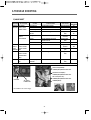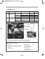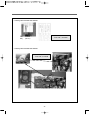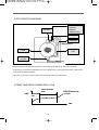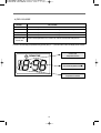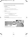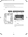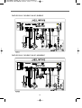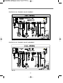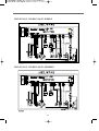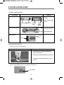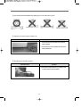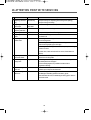
1
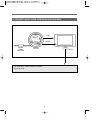
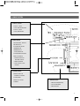
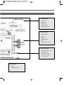
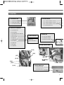
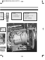
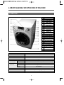
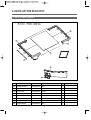
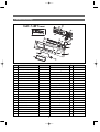
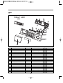
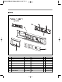
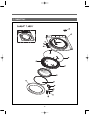
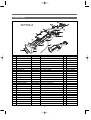
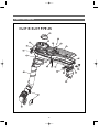
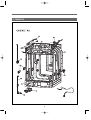
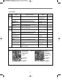
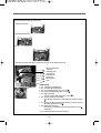
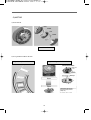
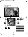
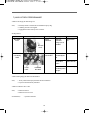
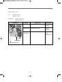
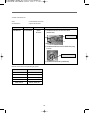
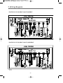
S/M No. : WDE1211001
Service Manual
DRUM WASHING MACHINE
Model: DWD-E6213
✔ Caution
: In this Manual, some parts can be changed for improving,
their performance without notice in the parts list. So, if you
need the latest parts information, please refer to PPL(Parts
Price List) in Service Information Center
Dec. 2005
DRUM WASHING MACHINE
SERVICE MANUAL
1. WHAT IS DRUM? ..........................................................................2
2. SPECIFICATION OF DRUM WASHING MACHINE .....................6
3. VERIFICATION OF DRUM ASSY ................................................7
4. PARTS LIST FOR EACH ASSY ....................................................8
5. SEQUENCE CHART OF PCB.....................................................23
6. TROUBLE SHOOTING ...............................................................31
7. WIRING DIAGRAM .................................................................... 47
8. TROUBLESHOOTING REGARDING DRAIN .............................55
9. INSTALLATION GUIDE ...............................................................56
10. ATTENTION POINT WITH SERVICE........................................58
1. WHAT IS DRUM ?
1. WHAT IS DRUM WASHER?
One of the famous washers in the globe which uses laundry falling energy.
2. Sales point of our washer
❖ The biggest capacity with compact size
❖ Environmently friendly washer with NANO technology
• Sterilizing up to 99.9%
❖ No damage and entanglement but excellent washability
❖ 4way savings-noise, vibration, washing times, energy
❖ Self-cleaning course of Drum
❖ Good washing performance with heating system
❖ Condensing dry system with saving energy
❖ Sunshine dry effects with infrared x-ray
❖ Big door glass with easy laundry take-in/out
❖ The higest spin speed - 1200rpm
2
3. THE DIRECT DRIVE SYSTEM OF DRUM WASHING MACHINE
TUB
WASH
DRUM
DRAIN
PUMP
(MOTOR)
LIFTER
BLDC
• DD CONTROL : DIRECT DRIVE SYSTEM
• BLDC MOTOR
3
4. DRIVE SYSTEM
3. INLET PARTS
• COLD : 3-WAY
- COLD, PREWASH, DRY
• COLD : 2-WAY
- COLD, PREWASH
6. DRY PARTS
• HEATER DRY : OPTION
• BLOWER FAN
• FAN MOTOR : BLDC
• THERMISTOR
• THERMOSTAT
: FUSE, BI-METAL
• CONDENSING SYSTEM
• DRY FAN DRIVE
→ GENERATION OF
HEATER’S HEAT
→ TEMP. SENSOR
→ 100°C OFF 90°C ON :
OPTION
DRAIN PARTS
5. DOOR PARTS
• DOOR LOCK S/W
: ADDING CLOTHES
• LOCK HINGE
• DOOR AS : GLASS
• GASKET
7. DRAIN PARTS
• DRAIN PUMP(MOTOR)
• VALVE HOUSING
• DRAIN HOSE I
4
1. CONTROLLER
• MAIN PCB
• FRONT PCB
• HARNESS
• NOISE FILTER
• POWER CORD : 15A
2. DRIVE PARTS
• BLDC MOTOR
• DRUM
• BEARING
• SPIDER/SHAFT
• TUB
• WEIGHT BALANCER
4. WASH HEATING
• WASH HEATER : OPTION
• THERMISTOR
• 40°C FIXED TEMP.
CONTROL : OPTION
• 60°C, 90°C BOIL
8. SUPPORTER
• BASE
• DAMPER AS : 3(70N)
4
5. FUNCTION
1. CONTROLLER
3. INLET PARTS
(1-1) MAIN PCB
(1-2) FRONT PCB
(1-3) NOISE FILTER
(3-1) 3-WAY INLET VALVE
(3-1) 2-WAY INLET VALVE
(3-2) 1-WAY INLET VALVE (HOT)
(3-3) INLET BOX AS
2. PARTS for DRIVING
(2-1) LIFTER AS
(2-2) GASKET
(2-3) WEIGHT BALANCER
(2-4) ROTOR
(2-5) STATOR
(2-6) SHAFT
(2-7) BEARING
(2-8) SPIDER
(2-9) DRUM
(2-10) TUB
(2-11) BASE
4. DOOR AS
BLDC MOTOR
PARTS for
TRANMITTING
(4-1) GLASS DOOR
(4-2) HINGE DOOR
(4-3)DOOR LOCK S/W
5. DRY : DUCT B AS
• HEATER DRY
(2-9)
(2-8)
(2-7)
(2-7)
(2-10)
(2-4)
(2-6)
• FAN
• FAN
MOTOR
• BI-METAL
S/W
• TEMP. FUSE
(2-5)
(2-11)
• TEMP.
SENSOR
6. WASH HEATING
• WASH HEATER
• THERMISTOR
5
7. DRAIN
8. SUPPORTER
(7-1) PUMP AS
(7-2) HOSE DRAIN I
(7-3) HOSE DRAIN
HOT)
(3-2)
(8-1) BASE U
(8-2) DAMPER AS : 3(70N)
(8-3) SPRING :
FRONT - 2 (BLACK)
REAR - 2 (YELLOW)
(5)
(3-3)
(1-2)
(2-2)
(3-1)
ATER DRY
(8-3)
(4-3)
(4-1)
(4-2)
(2-1)
• TEMP.
SENSOR
EMP. FUSE
(2-3)
(6)
(7-2)
(7-1)
(1-3)
5
(1-1)
(8-2)
(7-3)
(8-1)
2. DRUM WASHING SPECIFICATION OF MACHINE
1. PANEL TYPE 1
NO
PARTS NAME
1
FRME DOOR O
2
DOOR WINDOW
3
DCD STICKER
4
PANEL LOWER
5
CABINET FRONT
6
PANEL LOWER
7
FRAME TOP F
8
FRAME TOP R
9
CABINET
10
PLATE TOP
11
CASE HANDLE
12
HANDLE CAP
13
BADGE
14
WINDOW DISPLAY
15
DECO. WINDOW
16 BUTTON DOOR UNLOCK
17
BUTTON FUNCTION
18
DECO. FUNCTION
19
PLATE DISPENSER
20
BUTTON POWER
21
BUTTON DIAL OUT
22
BUTTON DIAL IN
23
BUTTON DIAL IN
24
HOLDER COURSE IN
25 HOLDER COURSE OUT
26
HANDLE CABINET
27
BASE UNDER
DIMENSION(WxDxH)
630mm(W) x 755mm(D) x 950mm(H)
MACHINE WEIGHT
90 / 85kg
WASH 130 l/ DRY 28 l
WATER CONSUMPTION
32 l
WASHING CONSUMPTION
POWER SOURCE
Option
POWER
WASHING
CONSUMPTION
DRY
1100W (Heating ) ~ 2400W : Option
WASHING
11 kg (Domestic)
CAPACITY
SPIN
11 kg (Domestic)
DRY
6.5 kg (Domestic)
1250W ~2400W : Option
WASHING TYPE
DRUM TYPE
DRY TYPE
Digital condensing dry system
OPERATION WATER PRESSURE
29kPa ~ 784kPa(0.3kgf/cm2~8kgf/cm2)
6
3. VERIFICATION OF DRUM ASSY
7
7
4. PARTS LIST FOR EACH ASSY
1. PLATE T, PANEL LOWER AS
No.
PARTS NAME
PARTS CODE
DESCRIPTION
Q’TY
A01
FRAME PLATE F
3612204400
HIPS
1
A02
FRAME PLATE REAR
3612204500
HIPS
1
A03
PLATE TOP
3614531600
WOOD
1
A04
PAD CUSHION
3614110500
SPONGE
1
A05
FIXTURE PLATE T
3612007100
STAPLE(8x10)
1
SCREW TAPPING
7122401411
T2S TRS 4x14 MFZN
2
A06
PANEL LOWER
3614284200
HIPS
1
A07
COVER PRMP
3611426400
HIPS
1
8
REMARK
2. PANEL F AS(Luxury)
No.
B01
B02
B03
B04
B05
B06
B07
B08
B09
B10
B11
B12
B13
B14
B15
B16
B17
B18
B19
PARTS NAME
PANEL F
HOLDER COURSE OUT
HOLDER COURSE IN
DECORATOR POWER
BUTTON POWER IN
BUTTON POWER OUT
BUTTON DOOR LOCK
DECORATOR FUNCTION
BUTTON FUNCTION
SCREW TAPPING
WINDOW DISPLAY
DECORATOR WINDOW
HOLDER POWER
HOLDER COURSE MAIN
BUTTON DIAL MIDDLE
BUTTON DIAL OUT
BUTTON DIAL IN
CUSTOM LED
CASE PCB FRONT
PCB
SCREW TAPPING
PARTS CODE
3614282200
3613049000
3613048900
3611631000
3616602800
3616602900
3616602600
3611630900
3616602700
7121301508
3615502700
3611630800
3613048800
3613049100
3616602400
3616602500
3616602300
3613014400
3611139600
PRPSSWD15
PRPSSWD16
7122401411
9
DESCRIPTION
ABS
ABS, GUILDING_BASE
ABS(TR558)
ABS, UV_BASE
ABS
ABS(TR558)
ABS
ABS, GILDING_BASE
ABS, UV_BASE
T2S PAN 3x15 MFNI
ABS(TR558)
ABS, GILDING_BASE
ABS(TR558)
ABS
ABS, GILDING_BASE
ABS(TR558)
ABS, GILDING_BASE
ABS
HIPS
E1211R/P
E1211W/P
T2S TRS 4X14 MFZN
Q’TY
REMARK
1
1
1
1
1
1
1
1
1
3
1
1
1
1
1
1
1
1
1
1
DRY
1
WASH
7
■ Mid
No.
B01
B02
B03
B04
B05
B06
B07
B08
B09
B10
B11
B12
B13
B14
B15
PARTS NAME
PARTS CODE
PANEL F
3614282300
WINDOW LED COURSE
3615502900
DECORATOR DIAL
3613049400
DECORATOR BUTTON POWER 3611631100
BUTTON POWER
3616603100
BUTTON DOOR OPEN
3616603200
BUTTON FUNCTION
3616603000
SCREW TAPPING
7121301208
HOLDER LED COURSE
3613049300
HOLDER LED CUSTOM
3613049200
CASE PCB F
3611139600
SCREW TAPPING
7122401411
PCB
PRPSSW2D10
SUTTON DIAL OUT
3616603400
BUTTON DIAL IN
3616603300
WINDOW DISPLAY
3615502800
CASE HANDLE
3611139700
10
DESCRIPTION
ABS
ABS(BK 8410AT)
ABS
ABS
ABS
ABS
ABS
T2S PAN 3x12 SUS
ABS
ABS
HIPS
T2S TRS 4x14 MFZN
–
ABS
ABS
ABS(BK 8410AT)
ABS
Q’TY
REMARK
1
1
1
1
1
1
1
3
1
1
1
7
1
1
1
1
1
INLETBOX AS
■ Cheap
No.
PARTS NAME
PARTS CODE
DESCRIPTION
Q’TY
B01
PANEL F
3614282400
ABS
1
B02
HOLDER LED COURSE
3613049500
ABS
1
B03
HOLDER LED CUSTOM
3613049200
ABS
1
B04
CASE PCB F
3611139900
HIPS
1
B05
PCB
PRPSSW4D10 –
1
SCREW TAPPING
7122401411
T2S TRS 4x14 MFZN
3
B06
DECORATOR FILM
3611632600
PC FILM
1
B07
CASE HANDLE
3611139800
ABS
1
11
REMARK
INLETBOX AS
3. CABINET F AS
12
No.
PARTS NAME
PARTS CODE
DESCRIPTION
Q’TY REMARK
C01
CABINET F
3610811000
SECD, 0.8t
1
C02
PLATE HINGE SUPPORT
3614531500
SPG, 1.6t
1
C03
HINGE DOOR
3612902700
ALDC
1
C04
CAP HINGE DOOR
3610916500
POM
1
C05
SCREW TAPPING
3616030000
F/L BOLT(SE) 5x12 SUS
3
C06
SPRING DOOR
3615113800
D=1.0, N=7
1
C07
CLAMP DOOR
3611204200
HWSR3, D=1.4
1
C08
FLAME DOOR I
3611204700
PP
1
C09
STOPPER DOOR
3615202300
PP
3
C10
SCREW TAPPING
7122401608
T2S TRS 4x16 SUS
2
C11
SCREW TAPPING
7115402008
T1S FLT 4x20 SUS430 NATURAL
15
C12
DOOR GLASS
361A110600
GLASS(DWD-100DR)
1
C13
PROTECTOR GLASS
3618304201
ABS TRANSPATENT
1
C14
FRAME DOOR O
3612204600
ABS
1
CR
C15
COVER HANDLE
3611425620
ABS
1
CR
C16
SPRING HOOK
3615113700
SUS, ID=3, NI=7, D=ø0.9
2
C17
PIN HANDLE
3618200100
SUS, D=3.0, L=39
1
C18
HOCK DOOR
3613100700
Zn-DC
1
C19
HANDLE DOOR
3612608200
ABS
1
C20
SWITCH DOOR LOCK
3619046410
DF F11 110 125V 16A
1
3619046400
DF F01 007 220V 16A
1
13
4. INLET BOX AS
No.
D01
D02
D03
D04
D05
D06
D07
D08
D09
D10
D11
D12
D13
D14
PARTS NAME
HANDLE CAP
CASE HANDLE
SCREW TAPPING
CASE DETERGENT
CAP SOFTENER
INLETBOX
NOZZLE AS
PACKING
HOSE INLET
CLAMP AS
HOSE C
HOSE A
HOSE B
CLAMP SPRING
VALVE INLET
D15
VALVE INLET
D16
D17
PIPE JOINT
HOSE SHOWER
PARTS CODE
3612608300
3611139400
7121301208
3611139500
3610916600
3617505300
3618103500
3614010000
3613266400
3611203200
3613267010
3613266600
3613266700
3611203800
3615415900
3615415000
3615415010
3615415800
3615414900
3615414910
3615415700
3615414800
3615414810
3614413300
3613270100
DESCRIPTION
Q’TY
REMARK
ABS
1 Luxury
ABS
1 Luxury
T2S PAN 3x12 SUS
2 HANDLE CAP
PP
1
PP
1
PP
1
PP, DWD-100DR
1 TOP+UNDER
EPDM
1
EPDM
1
ID=60, WIRE+GUIDE+BOLT+NUT
1 INLET BOX/TUB R
EPDM, ID=10, OD=16, L=165mm
2 PRE WASH
EPDM, ID=10, OD=16, L=335mm
1 MAIN WASH
EPDM, ID=10, OD=16, L=420mm
1 HOT
ID=15.5, T=0.6, B=10
8
100/130V, 3WAY, PP/BRACKET
1
COLD
220/240V, 50/60Hz, 3WAY
1 COLD
220/240V, 3WAY, NYLON/BRACKET 1 COLD, VDE
100/130V, 2WAY, PP/BRACKET
1 COLD
220/240V, 50/60Hz, 2WAY
1 COLD
220/240V, 2WAY, NYLON/BRACKET 1 COLD, VDE
100/130V, 1WAY, PP/BRACKET
HOT
220/240V, 1WAY, PP/BRACKET
HOT
240V, 1WAY, PP/BRACKET
1 HOT-AUS
PP
1
EPDM, ID=8.5, OD=12.5, L=620
1
14
5. DUCT + DUCT PIPE AS
15
■ Duct + Duct pipe as
No.
PARTS NAME
PARTS CODE
DESCRIPTION
E01
UNIT FAN MOTOR
36189L3Z41 ISM-77806DWWA, 24V CW 8P 14W
1
E02
COVER DUCT
3611426600
1
E03
DUCT B UPPER
361A200200 AL, 2.5T, DWD-100DR
1
E04
CLAMP CORD
3611203330
DABE-1, A=9, B=5.3, L=105
4
E05
FAN AS
3611885700
Ø133x45L IMPELLER
1
E06
SCREW TAPPING
7122400811
T2S TRS 4x8 MFZN
3
E07
WASHER PLAN
7400432011
PW4.3x20xIT
1
E08
FUSE TEMPERATURE
361A800120 120°C DF-128S 15A 250V VDE
1
E09
FRAME HEATER FRANGE
3612204100
1
E10
DUCT B THERMOSTAT
361A200100 AL
1
E11
PACKING THERMOSTAT
3614009900
SILICON
1
E12
SWITCH THERMOSTAT
3619046500
ON 120°C, OFF 150°C 230V
1
E13
HEATER DRY
3612800900
220V 210W, 23.050HM, 6.1W/SQ
1
3612801400
230V 2.1KW, 25.190HM, 6.1W/SQ
1
3612801600
240V 2.1KW, 27.430HM, 6.1W/SQ
1
3612801300
110V, 1.2KW, 10.080HM, 3.5W/SQ
1
3612801800
120V 1.2KW, 120MH 3.5W/SQ
1
PBT+GF30%
SBHG 1.0T
Q’TY
E14
THERMISTOR DRY
361AAAAC00 R40=26.065k, R90=4.4278k
1
E15
PACKING RUBBER
3614009800
SILICON, DWD-100DR
1
E16
CUSHION DRY
3611562800
NBR, DWD-100DR
2
E17
GASKET SEAL A
3612320820
DWD-110RP, O TYPE ø5, L=1385
1
E18
GASKET SEAL B
3612320830
EPDM FOAM L=415, ø5
1
E19
GASKET INLET
3612320900
DWD-100DR
1
E20
DUCT GUIDE
361A201000 ALDC, DWD-110RP
1
E21
DUCT PIPE AS
361A200700 11kg
1
E22
CLAMP AS(DUCT)
3611203700
DUCT
2
E23
BELLOWS DUCT
3616403000
EPDM
1
16
REMARK
6. CABINET AS
17
■ Cabinet As
No.
PARTS NAME
PARTS CODE
DESCRIPTION
Q’TY
F01
NOZZLE AIR
3618103110
PP, DWD-100DR
1
F02
FRAME TOP R
3612204300
GI, 1.6T, DWD-100DR
1
F03
FRAME TOP L
3612204900
GI, 1.6T, DWD-100DR
1
F04
CABINET
3610810900
SGCC 0.8T, PANTING, DWD-100DR 1
F05
COVER BACK AS
3611425510
COVER BACK_PAD
1
F06
STOPPER SPRING
3615202200
POM, DWD-100DR
4
F07
UNIT DRAIN PUMP AS
36189L4F00 220~240/50Hz, B20-6
1
36189L4E00 220/60Hz, B20-5
1
36189L4D00 110~130/50/60Hz, B20-3
1
REMARK
F08
FRAME UPPER
3612204000
SBHG 1.2T, DWD-100DR
1
F09
HANDLE CABINET
3612608100
PP, DWD-100DR
1
F10
FRAME LOWER
3512204200
SBHG 1.2T, DWD-100DR
1
F11
HOSE DRAIN I
3613269500
ST+EL, 840M
1
F12
CUFF DRAIN HOSE
3616802600
PP, PUMP
1
F13
HOSE SIPHON
3613269600
EPDM
1
F14
CLAMP HOSE
3611204700
D=27
1
F15
CORD POWER AS
3611339910
H05VV-F, 1.5SQx3C, 250V16A
1
EU-2PIN
3611339930
H05VV-F, 1.5SQ, 250V16A, FERRITE
1
EU-2PIN
3611339510
250V15A, IEC53, 1.5SQx3C
1
CP-2PIN
3611339310
H05VV-F, 1.5SQx3C, 250V16A
3611339810
VCTFK 2C 15A 125V
1
F-2PIN
3611340910
H05VV-F, 1.0SQx3C, 250V16A
1
ISRAEL
3611340710
H05VV-F, 1.5SQx3C, 250V15A
1
BS1363A
3611340310
H05VV-F, 1.5SQx3C, 250V16A
1
BS1363A
3611339710
H05VV-F, 1.5SQx3C, 250V15A
1
AUS
3611340110
H05VV-F, 1.5SQx3C, 250V10A
1
AUS
3611340010
H05VV-F, 1.5SQx3C, 250V
1
AUS
3611340610
H05VV-F, 1.5SQx3C, 250V10A
1
S.AFRICA
3611340410
16AWG 125V13A, #1806 3P
1
U.S.A
18
CP-2PIN
7. BASE U AS
19
■ Base u as
No.
G01
PARTS NAME
PCB AS
G02
G03
G04
RECTOR
BASE U
UNIT FILTER(EMI K19)
G05
G06
G07
SUPPORTER LEG
FIXTURE LEG
FOOT
SPECIAL BOLT
HARNESS AS
G08
PARTS CODE
PRPSSW7D05
PRPSSW7D06
PRPSSW7D07
PRPSSW7D08
PRPSSW7D09
PRPSSW7D10
PRPSSW8D05
PRPSSW8D06
PRPSSW8D07
PRPSSW8D08
PRPSSW8D09
PRPSSW8D10
PRPSSW9D05
PRPSSW9D06
PRPSSW9D07
PRPSSW9D08
PRPSSW9D09
PRPSSW9D10
52G043J003
3610391910
3611908000
3611908010
3615303600
3612006400
3612100600
3616029000
3612795510
3612795515
3612795550
3612795555
3612795530
3612795535
3612795570
3612795575
3612795500
3612795505
3612795540
3612795545
3612795520
3612795525
3612795560
3612795565
DESCRIPTION
Q’TY
REMARK
E1211R, DOUBLE VALVE
1 DRY
E1211W, DOUBLE VALVE
1 WASH
E1211R, SINGLE VALVE
1 DRY
E1211W, SINGLE VALVE
1 WASH
E1211R
1 DRY, 127V
E1211W
1 WASH, 127V
E1221R, DOUBLE VALVE
1 DRY
E1221W, DOUBLE VALVE
1 WASH
E1221R, SINGLE VALVE
1 DRY
E1221W, SINGLE VALVE
1 WASH
E1221R
1 DRY, 127V
E1221W
1 WASH, 127V
E1231R, DOUBLE VALVE
1 DRY
E1231W, DOUBLE VALVE
1 WASH
E1231R, SINGLE VALVE
1 DRY
E1231W, SINGLE VALVE
1 WASH
E1231R
1 DRY, 127V
E1231W
1 WASH, 127V
DWD-100DR, 8A
1
PP, DWD-100DR
1
220V(FUSE250V, 471+474+10MH) 1
100V(FUSE125V, 471+474+10MH) 1
PO, 3.0T
4
ABS, DWD-100DR
4
BUTYL, DWD-100DR
4
10x1.25, 51mm
4
E1211W, DOUBLE VALVE
1 BUBBLE
E1211W, DOUBLE VALVE
1 N/BUBBLE
E1211W, SINGLE VALVE
1 BUBBLE
E1211W, SINGLE VALVE
1 N/BUBBLE
E1221W, DOUBLE VALVE
1 BUBBLE
E1221W, DOUBLE VALVE
1 N/BUBBLE
E1221W, SINGLE VALVE
1 BUBBLE
E1221W, SINGLE VALVE
1 N/BUBBLE
E1211R, DOUBLE VALVE
1 BUBBLE
E1211R, DOUBLE VALVE
1 N/BUBBLE
E1211R, SINGLE VALVE
1 BUBBLE
E1211R, SINGLE VALVE
1 N/BUBBLE
E1221R, DOUBLE VALVE
1 BUBBLE
E1221R, DOUBLE VALVE
1 N/BUBBLE
E1221R, SINGLE VALVE
1 BUBBLE
E1221R, SINGLE VALVE
1 N/BUBBLE
20
8. TUB AS
21
■ Base u as
No.
H01
H02
H03
H04
H05
H06
H07
H08
H09
H10
H11
H12
H13
H13
H14
H15
H16
H17
H18
H19
H20
H21
H22
H23
H24
H25
H26
H27
H28
H29
H30
H31
PARTS NAME
BALANCER WEIGHT AS
PIPE JOINT
CLAMP(HODE PIPE)
HOSE JOINT
GASKET
PARTS CODE
3616106200
3614404900
3611204300
3613266500
3612320700
3612321200
CLAMP GASKET AS
3611203600
SPRING SUSPENSION F 3615113500
TUB FRONT
3618820401
FIXTURE HEATER
3612006700
DAMPER PIN
361A700200
DAMPER FRICTION
361A700100
DRUM AS
3617003300
UFT AS
361A400300
LIFT
361A400600
SPIDER AS
361A300200
DRAIN HOUSING I
36196TAM00
HOSE DRAIN
3613269000
AIR TRAP AS
3610AAR101
SPRING SUSPENSION R 3615113600
GASKET TUBE
3612321100
WATER SEAL
361A600100
BEARING INNER
3616303100
BEARING HOUSING
3616303000
BEARING OUTER
3616303200
HOSE AIR
3613266300
UNIT BUBBLE PUMP
36189L4110
36189L4G00
BASE
3610392000
UNIT STATER BLDC
36189L4800
UNIT ROTOR BLDC
36189L4900
HEATER WASH
3612800800
3612801200
3612801500
3612801100
3612801900
NOZZLE SHOWER
3618104000
CLAMP HOSE
3611203410
DESCRIPTION
Q’TY
6.5kg
1
PP
1
ø14, MFZN
1
EPDM
1
EPDM, DRY
1
EPDM, WASH
1
GASKET
1
YELLOW
2
PP+GF, FH7300GM
1
SUS
1
AKS, D=14.5
3
70N AKS ST=170-260
3
11kg
1
11kg
1
PP
1
11kg
1
PP, PUMP
1
EPDM, PUMP
1
110RP, HOSE+TRAP
1
BLACK
2
EPDM FORM
1
NBR
1
6206Z, FAG
1
ALDC
1
6205Z, FAG
1
EPDM
1
220-240V, 50/60Hz
1
100-130V, 50/60Hz
1
SECEN
1
ø256x28H, 36 SLOT, 2SENSOR
1
MAGNET24, SERRATION:3114D02000 1
230V 2KW, 24.20HM, 8.6W/SQ
1
2220V 2KW, 26.450HM, 8.6W/SQ
1
240V 2KW, 28.80HM, 8.6W/SQ
1
110V 1KW, 4.3W/SQ SUS
1
120V, 1KW, 14.4MH, 4.3W/SQ SUS 1
PP
1
SK5, D+33
1
22
REMARK
5. SEQUENCE CHART OF PCB
1. SEQUENCE CHART
Process Time
Pre.
Wash
W
a
s
h
i
n
g
Sensing
Water Supply
Pre. Wash
Drain
Balancing Spin
Mid.Spin
Sensing
Water Supply
Washing1
(Heating)
Washing 2
R
i
n
s
e
S
p
i
n
Drain
Balancing Spin
Mid.Spin
Water Supply
Rinse 1
Drain
Balancing Spin
Mid.Spin
Water Supply
Rinse 2
Drain
Balancing Spin
Mid.Spin
Water Supply
Rinse 3
Drain
Balancing Spin
Main Spin
20sec
2min
10min
8min
1min
1min
3min
20sec
2min
90min
80min
35min
30min
25min
25min
20min
15min
1min
1min
3min
2min
3min
1min
1min
3min
2min
3min
1min
1min
3min
2min
3min
1min
1min
7min
5min
3min
60sec
10sec
Cotton
Synthetic
Heavy
Stain
Small Middle
Small
Middle
ECO-White
Small
Middle
Small
Middle
■
■
■
■
■
■
■
■
■
■
■
■
■
■
■
■
■
■
■
■
■
■
■
■
■
■
■
■
■
■
■
■
■
■
■
■
■
■
■
■
■
■
■
■
■
■
■
■
■
■
■
■
■
■
■
■
■
■
■
■
■
■
■
■
■
■
■
■
■
■
■
■
■
■
■
■
■
■
■
■
■
■
■
■
■
■
■
■
■
■
■
■
■
■
■
■
2:22
■
■
2:32
■
■
1:37
■
■
1:52
■
■
■
■
■
■
■
■
■
■
■
■
■
■
■
■
■
■
■
■
■
■
■
■
■
■
■
■
■
■
■
■
■
■
■
■
■
■
■
■
■
■
■
■
■
■
■
■
■
■
■
■
■
■
■
■
■
■
■
■
■
■
Crease care
■
■
■
■
END
■
■
■
■
Remain Time Display
1:27 1:32
1:27
1:55
NOTE
1.Heavy Stain Course: Pre.Wash is Basic Default.
End
Whites
23
Process Time
W
a
s
h
i
n
g
Sensing
Water Supply
"Wash 1
(Heating)"
Wash 2
R
i
n
s
e
S
p
i
n
Drain
Balancing Spin
Mid.Spin
Water Supply
Rinse 1
Drain
Balancing Spin
Mid.Spin
Water Supply
Rinse 2
Drain
Balancing Spin
Mid.Spin
Water Supply
Rinse 3
Drain
Balancing Spin
Mid.Spin
Crease care
D
R
Y
Dry
20see
2min
60min
50min
35min
30min
15min
40min
20min
15min
1min
1min
3min
2min
3min
1min
1min
3min
2min
3min
1min
1min
3min
2min
3min
1min
1min
7min
5min
3min
60sec
15min
10min
5min
10sec
30min
60sec
10sec
Wool
Delicate Blanket
Rapid
Small
Small
Middle
Middle
■
■
■
■
Drum
Memory
cleaning
High
■
■
■
■
■
■
■
■
■
■
■
■
■
■
■
■
■
■
■
■
■
■
■
■
■
■
■
■
■
■
■
■
■
■
■
■
■
■
■
■
■
■
■
■
■
■
■
■
■
■
■
■
■
■
■
■
■
■
■
■
■
■
■
■
■
■
■
■
■
■
■
■
■
■
■
Cooling
■
END
■
Crease care
■
Crease care
■
■
■
End
END
■
■
■
Remain Time Display
46
46
1:07
1:10
NOTE
1. In Rapid and Drum cleaning program, dry is default function.
2. This chart will be changed depend on market condition.
24
■
■
■
1:48
2. Main function of PCB program
2-1. LOAD SENSING
1) Deciding the water level
1 Cotton, Whites, ECO-White course will be followed by this process.
2 Check the water level with dry laundry at the starting wash.
3 Check the water level by using motor output data during 20 sec, 65 rpm.
2) Deciding Spin Starting Step.
1 Check after finishing washing step with wet laundry.
2 Checking by using motor output data during 20 sec, 65 rpm.
3 The decided data is different depending on loading condition.
2-2. BALANCE SPIN
1) Motor running during balance spin.
1 Spreading the laundry : Rotating the same 45 rpm with left and right direction alternatively.
2 Attaching stop : Attaching the laundry to drum inside with constant speed.
3 Unbalance checking point : First step, check the U.B at 95 rpm, 160 rpm.
Second step, check the U.B at 95 rpm, 350 rpm.
Third step, at 300 rpm. if the unbalance data is over the criterion,
This process will be repeated.
4 Drain step : Drain at water around 160 rpm.
5 After drain, check the unbalance data again. This is so-called balance spin step.
2) Property of balance spin.
1 Conducting 10 times maximum.
2 If the washer can not pass balance spin step during 10 times, then water will be supplied.
3 If the washer can not pass 20 times of balance spin, UE error mode will be displayed on PCB.
25
2-3. DOOR S/W
1) The working principle of Door S/W
1 Door Locking
Bimetal on ( 3 sec) --> solenoid (supply 20msec pulse 2 times)
2 Door Unlocking
Bimetal off --> solenoid (supply 20msec pulse, until unlock)
3 After door locking, all parts can work normally.
4 After pressing power button, if the temperature of wash thermistor is over 50°C or the water level is
over the safety level, the door will be locked.
6 The door will be unlocked immediately after all processes are finished.
7 The door can be opened during processing if there is no problem to unlock.
26
2) DOOR OPEN SYSTEM
1If add the laundry during washing, press the door unlock button.
2Door open sequence at abnormal condition.
start / hold
door unlock button, 2sec.ON
water level is
less than safety level?
NO
drain
YES
NO
Temperature is
less than 50°C?
YES
Display <LOCK> off
Door open
27
fan motor on/
cold water supply
2-4. Child Lock
1 Press the “TEMP”. and “DRY” button simultaneously during processing.
2 Under the Child Lock function, only power button is working.
3 During Child Lock function, CHL will be displayed on PCB.
4 In order to unlock Child Lock mode, press "TEMP" and "DRY" simultaneously.
2-5. The sequence of drain
1 If the checking time to reset point is below 1 min, the remaining drain time is 30 sec.
2 If the checking time to reset point is over 1 min, the remaining drain time is 2 min.
3 If the checking time to reset point is over 10 min, OE singal will be appeared on PCB.
4 If the temperature is over 50°C, the water will be supplied to high water level, then the drain will
start.
28
3. Convenience service functions(test mode)
1. Testing Mode
PCB and other electronic parts will be tested without water supply whether they are normal or not.
1) Process : press power button --> press "SPIN" button 3 times with pressing "WASH" button --> 'L d' will be shown on LED -> Whenever pressing "TEMP" button 1 time, below process will be occurred.
L C (Lock Closed) --> F ( Fan Motor) ---> H (Hot V/V) --> C (Cold V/V) ->
P (prewashing V/V) -> d ( dry V/V) -> bb (bubble) -> dr (drain motor) ->
L O(Lock S/W Open)
2) More details
1When turn on 'LOCK' singal, all process is conducting normaly.
2When working starts, the PCB displys all the sensor conditions.
3In this case, BLDC Motor is not tested. In order to test it, select spin or rinse.
2. Continous testing mode
1) Process : after pressing "WASH", "RINSE", "SPIN" button simultaniously, press "POWER" button.
ALL LED On/Off 1 time --> L C (Lock Closed) ---> R (Motor right) --> L (Motor Left) --> F ( Fan Motor) ---> H
(Hot V/V) --> C (Cold V/V) --> b (pre-wash V/V)
--> d ( dry V/V) --> bb (bubble) --> h1 (HEATER WASH)--> h2(HEATER DRY) --> dr (DRAIN MOTOR On) ->L O(Lock S/W Open)
2) More tails
1LED test can be done with all LED On.
2All sensor conditions will be shown on PCB during processing.
29
4. ERROR DISPLAY
ERROR
SINGAL
ERROR
IE
WATER
INLET ERROR
CAUSE
1 inlet valve broken
2 PCB cannot control fan motor
Change the Inlet-Valve
Change the Drain Motor
Change the Sensor Pressure
Change the PCB
Change the Drain Motor
Change the Inlet-Valve
Change the Sensor Pressure
Change the PCB
rearrange the laundry
Clode the Door
Change the LOCK SW
Change the PCB
Change the Inlet-Valve
Change the Drain Motor
Change the Sensor Pressure
Change the Fan-Motor
The contact of the Connector or Change the PCB
1 abnormal water level
Change the Sensor Pressure
1 huge noise
re-installation
rearrange the laundry
Change the PCB
re-installation
rearrange the laundry
Change the Motor
Change the PCB
2 drain motor working during water supply
3 pressure switch disorder
4 PCB can not check water level
1 drain motor out of order
OE
DRAIN
ERROR
UE
UNBALANCE ERROR
LE
DOOR
OPEN ERROR
2 inlet valve working during drain
3 pressure switch disorder
4 PCB can not check water level
1 laundry unbalance
1 door opened during processing
2 LOCK S/W broken
3 PCB can not check door lock
1 continuous water supply
E2
Overflow
2drain motor can not work
3 pressure switch disorder
E3
E9
E5
FAN MOTOR
disorder
SENSOR PRESSURE
ERROR
HIGH VOLTAGE
ERROR
1 fan motor cannot work
2 spining with jamming clothes between gasket
3 PCB broken
1 huge noise
E6
EMG ERROR
2 spining with jamming clothes between gasket
3 motor broken
4 PCB broken
E7
Direction Error
1 move opposite direction
2 motor Hall IC broken
1 dry heater cannot work
check the connector and change
The contact of the Connector
check the loading condition and change
Change the Sensor Temp.
The contact of the Connector
Change the Sensor Temp.
The contact of the Connector
Change the Fan Motor
Change the Sensor Temp.
check water level
Change the Sensor Temp.
Change the Heater Wash
Change the Heater Dry
1 heater working with no water supply
check the water level and washing heater
1 The drain filter is clogged.
Clean the drain filter
1 connector problem
E8
motor disorder
H1
sensor temp.
dry disorder
1 sensor temp broken
H2
sensor temp.
wash disorder
1 sensor temp. of washing broken
H3
overheating
dry heater
H4
H6
H7
H8
PEF
overheating
wash heater
abnormal of washing heater
abnormal of drying heater
abnormal of sensor temp.
of washing
Pump Filter
COUNTERPLAN
2 abnormal loading condition
2 connector problem
2 connector problem
1 fan motor cannot move
2 sensor temp. of dry broken
1 heater working with no water supply
2 sensor temp. of wash broken
1 washing heater cannot work
30
6. TROUBLE SHOOTING
1) VALVE INLET
TROUBLE
SITUATION
WATER IS NO WATER
SUPPLIED SUPPLY WITH
"WING" SOUND
NO WATER
SUPPLY
WITH SILENCE
CAUSE
CHECK POINT
closed water tap
coil short
alien materal jammed
alien material inside
inlet valve
unfixing connector
check the water tap opened
check the resistance 4320~5280Ω
check the filter
coil short
check the resistance 4320~5280Ω
check the connector
check the pressure switch
check the hose torn or twisted
harness short
pressure s/w broken
THE WATER
SUPPLY START
pressure hose broken
WHEN POWER
"ON"
inlet valve broken
THE WATER
SUPPLY START
WHEN POWER
"OFF"
water leakage to the inlet valve poorly
Etc
assembled
side
Checking method of coil resistance, harness, connector.
WATER
SUPPLY
IS NOT
STOPPED
–
check the connector
–
check the leakage of inlet valve
PCB
ERROR MODE
Open the water tap
"IE"
"IE"
Clean the filter
"IE"
Change the InletValve
"IE"
The contact of the
"IE"
Connector
Change the Inlet"IE"
Valve
"IE"
Change the Sensor
Pressure
"E2"
Change the bad
"E2"
parts
Change the InletValve
SOLUTION
Change the InletValve
WASH VALVE(GREEN) :
COMMON(BLUE)/RESISTANCE TEST
PRE-WASH VALVE(RED) :
COMMON(BLUE)/RESISTANCE TEST
DRY VALVE(YELLOW) :
COMMON(BLUE)/RESISTANCE TEST
MAIN PCB
"8P" WHITE
CONNECTOR
COMMON(BLUE)
* "IE" ERROR : lack of water supply
31
-
2) PRESSURE SWITCH
TROUBLE
SITUATION
continuously inlet valve is normal,
water supply but continuous water
supply
"E9"
ERROR
water level frequence
below 15kHz or over
30kHz
CAUSE
CHECK POINT
SOLUTION
bellows problem
frequency Check : refer to below
hose problem
clogged hose
connector slipped out
pressure switch broken
frequency Check : refer to below
check the fine hole
check the hose condition
check the connector condition
frequency Check : refer to below
connector short
connector broken
change the
pressure switch
change the hose
change the hose
remove the alien
reconnecting
change the
pressure switch
PCB
ERROR MODE
"E2"
"E9"
Checking method of coil registance, harness, connector.
GROUND(GRAY)
OUTPUT
SIGNAL(WHITE)
INPUT SIGNAL
(PINK)
"12P" WHITE CONNECTOR
* E2 : overflow error ;Water level is higher than overflow level because of continuous water supply.
E9 : Pressure switch trouble, the frequency is less than 15kHz or more than 30kHz in the processing.
■ Checking method of the Frequency
1 Power ON
3 Press “TEMP” button
2 First, press the “DRY” button 3 times with pressing
1 time: water supply
the “WASH” button. The frequency of Air status will
2 times: stop the water supply
be appeared.
3 times: start the drain
ex) 623 ➝ 26.23kHz.
4 times: stop the drain
5 times: return to Air status mode
32
"E2"
"E2"
"E2"
"E9"
"E9"
3) DOOR LOCK SWITCH
1) CLASS
Failure
Status
"Tick"
Sound
"LE" Error
Details
Tick Sound happens
"LE" with tick sound
"LE" without tick sound
DOOR not Power Failure/Forced
Power Off during
open
operation
Power on state
PCB
ERROR MODE
When Door is locked/unlocked, this Solenoid Working
Normal Sound
sound is heard.
check the joining status of
Assemble Connector
Connector slipped out
"LE"
connector by eye
Close Door securely
DOOR closed loosely
"LE"
Replace DOOR AS
Failure of DOOR HOOK "LE"
Tick sound happen
CATCH CAM broken
"LE"
Replace DOOR S/W
check the joining status of
Connector slipped out
"LE"
Assemble Connector
connector by eye
Refer to below checking
Terminal slipped out
"LE"
Insert Receptacle no.2
method.
or no.3
Refer to below checking
Solenoid Coil
"LE"
Replace DOOR S/W
method.
Disconnection
During operation, "Power Failure" or "Forced Power S/W OFF" causes door not to be opened until
maximum 5 minutes pass.
Cause
Water remained in tub
Diagnosis of Failure
Solution
Check whether the water
After draining water,
level is over safety level.
open the door
Prevent the burn due to hot temp. after dry.
-
hot temp. in tub
Follow below process
ETC
Checking Method of wiring/coil disconnection, connector slipping out on PCB board : Operate with the Door lock switch connected
1. Replacing method of DOOR LOCK SWITCH
1) Open DOOR, disassemble CLAMP SPRING for fixing gasket
2) Disassemble GASKET
3) Disassemble two screws for DOOR LOCK S/W
4) Disassemble DOOR LOCK S/W
5) Assemble in the reverse order
33
2. Checking method of DOOR LOCK SWITCH
PIN
2345
array
(No no.1)
Between No. 3 & No.4
: if 156 ~ 234Ω, it is normal
3. Checking method of DOOR LOCK SWITCH
Between Viloet and Blue wire
: If 156 ~ 234Ω, it is normal
34
4) HEATER
Failure
Cause
Status
Can not Wiring Disconnection
heat
Heater Wash
water
Disconnection
Connector/Terminal
Seclusion
Heater Wash/Thermistor
Wash Poor
Overheat Heater Wash/Thermistor
Wash Poor
water
Can not Wiring Disconnection
dry
Heater Dry Disconnection
Fuse Temp.
Diagnosis of Failure
Check whether disconnected or not : See Fig. A
Check whether disconnected or not : if normal, the
resistance between two ends is 23.3~25.7Ω.
Check whether disconnected or not : See Fig. A
Measure the resistance of two ends of the sensor : if
11.981KΩat R25, it is mormal
Measure the resistance of two ends of the sensor : if
11.981KΩat R25, it is mormal
Check whether disconnected or not : See Fig. B
Check whether disconnected or not : if normal, the
resistance between two ends is 22.3~24.7Ω.
Shipped out
Connector/Terminal
Slipped out
Check whether disconnected or not : See Fig. B
Operation Trouble of FAN
MOTOR
Excessive Noise : Restraint/Failure of Fan Motor
Heater Wash/Thermistor
Fault of Thermistor (Dry)
Fan slipped out : MOTOR is operating, but there is
rotating sound.
Measure the resistance of two ends of the sensor : if
26.065KΩ, it is mormal
PCB
Error Mode
Solution
Connecting the
disconnecting point
Replacing Heater Wash
"H6"
terminal/connector tightly
Connecting
Replacing temp. sensor
"H6"
Replacing Heater Wash
"H2" or "H4"
Inserting terminal/connector
"H7"
Replacing Fuse Temp.
"H7"
tightly
Connecting
Re-connecting
"H7"
"H6"
"H2"
"H7"
Replacing Fan motor
"H7" or "E3"
Re-assemble after
disassembling
Replace Thermistor
"H7"
"H1"
Checking Method of wiring/coil disconnection, connector slipping out on PCB board : Operate with the heater connected
[Figure A]
* Inspect Wiring/Heater
Wash Disconnection :
Check the current and
resistance of two
terminals
[Figure B]
* Inspect
Wiring/Heater Dry
Disconnection :
Check the current
and resistance of two
terminals
3P Connector
orange wire
3P Connector
Red Wire
1P Connector
Blue Wire
1P Connecor
Blue Wire
35
* Replaceing method of Heater and Temp. Sensor
1. Disassemble Connector
2. Disassemble EARTH and NUT for fixing heater
3. Replace heater & sensor
4. Assemble in the reverse order. Be sure to assemble in the order : Nut for heater-Nut for EARTH.
* Structure of DUCT B As
1. Heater Dry
2. Diecasting DUCT
3. Thermistor Dry
4. FAN MOTOR
5. Fuse Temp.
6. Switch Bimetal
7. FAN
* ERROR MODE
1. "H1" : Thermistor Dry OPEN/SHORT
2. "H2" : Thermister Wash OPEN/SHORT
℃)
3. "H3" : Dry Overheating(Sensing Temp. is over 125℃
℃)
4. "H4" : Wash Overheating(Sensing Temp. is over 95℃
5. "H5" : Wash Overheating
℃)
(In Wool, Lingerie courses sensing temp. is over 45℃
6. "H6" : Abnormal condition of Heater Wash
(when the temp. increase at 10 minutes after heater operation is under 10
℃)
7. "H7" : Abnormal condition of Heater Dry(when the temp. increase at 10 minutes
℃)
after heater operation is under 10℃
8. "H8" : Heater Wash Overheating
℃
(when the temp. increase within 30sec after heater operation is over 5℃
without water)
9. "E3" : FAN MOTOR Broken(no signal from HALL IC)
36
5) MOTOR
1) BLDC MOTOR
Rotor
Insulator
Core
Insulator
BLDC MOTOR
2) Driving mechanism of BLDC MOTOR
Magnetic density flow of BLDC Motor
Sequence diagram of BLDC MOTOR
electromagnet
generating high power by rotator
(a permanent magnet) and stator
(multiple coils)
37
6) DRY SYSTEM(OPTION)
1) DRY SYSTEM
E
D
F
G
C
H
B
A
DIVISION
A
B
C
D
E
F
G
H
I
J
I
38
PARTS NAME
DUCT COVER
FAN MOTOR
HEATER DRY
DUCT B UNDER
VALVE INLET(DRY)
THERMOSTAT(Bie-METAL)
THERMISTOR
DUCT B UPPER
FAN AS
FUSE TEMPERATURE
J
2) DRY FUNCTION DIAGRAM
T : Thermistor
(CONTROL
HEATER’S
TEMPERATURE )
DRY DUCT
HEATER
T
FAN MOTOR
WATER SUPPLY
CONDENSING
DUCT
DRUM
DRAIN
HOUSING
While rotating DRUM, DRY HEATER applice heat to air and FAN blows it into DRUM evaporating water in the laundry.
• Evaporated water is sucked into CONDENSING DUCT, and condensed in DUCT contacting WATER SUPPLY (condensed water
is extracted through DRAIN HOUSING).
• Dry function is performed by continuous repetition of evaporating and condensing circulation as above.
3) TEMP-TIME GRAPH DURING DRY CYCLE
DRYING PROCESS
ZONE
건조진행구간
TEMP.
온도
INSIDE
TEMPERATURE
DRUM
OF DRUM
내부온도
PRE예열
HEATING
ZONE
구간
TIME
시간
39
4) DRY COURSE
COURSE
LOW TEMP.
IRON
DRY COURSE
Heater control temperature is 60°C On/70°C Off
Heater control temperature is 60°C On/70°C Off, with good condition for ironing
STANDARD
Heater control temperature is 87°C On/95°C Off, drying time is 166 min
STRONG
Heater control temperature is 87°C On/95°C Off, drying time is 216 min
SELECTING TIME
Heater control temperature is 87°C On/95°C Off, customer can select the dryting time as
1Hr, 2Hr, 3Hr.
In order to check the drying temperature during process going on : --> press the "DRY" button, the display shows as below.
UPPER LED:
Temperature for DRY
REMAIN TIME
남은시간
℃
The current temperature is 98℃
분
LOWER LED:
Temperature for WASH
40
5) TROUBLE SHOOTING OF DRY SYSTEM
✦ HEATER DRY
Function : heating the air during dry
• FAILURE MODE : * "H7" - The air cannot be heated to 10°C during 2 min.
• CHECKING METHOD : * Check the resistance of heater coil and replace with new one.
✦ Thermistor
Function : sensing the air temperature.
• FAILURE MODE : * The air cannot be heated even though water is supplied.
* "H1" - shot or cut-off
* "H3" - air temp. is reached over 150°C
• CHECKING METHOD : * Check the resistance of thermistor, replace with new one.
✦ FUSE TEMPERATURE
function : protecting from the fine hazard or overheating, if the temp., rises over 128°C, power supply will be cut-off.
• Pictures
FIXED BY
WASHER
+
SCREW
• FAILURE MODE : Dry is not performed.
• CHECKING METHOD : Check if fuse is short, and replace with new one.
41
✦ SWITCH THERMOSTAT(BIMETAL)
function : control the duct temperature, if the temp reached over 150°C, all power supply will be cut. and if the temp go down
120°C the power will be ON.
protecting overheating by cutting off heater power supply if the temperature rises over 150°C, and reoperating heater
by connecting heater power supply if the temperature falls under 120°C.
• OPERATING TEMPERATURE
• PICTURE
OPEN TEMPERATURE(OFF)
℃±5℃
℃
150℃
CLOSE TEMPERATURE(ON)
℃±5℃
℃
120℃
✦ UNIT FAN MOTOR
function : circulating the inside air during dry process.
• SPEC
• PICTURE
ITEMS
SPEC
RATING VOLTAGE
24V
RPM
MOTOR
3700 ± 10%
DUCT FAN AS
1900 ± 10%
ROTAING DIRECTION
CW
• FAILURE MODE : * E3 shown : FAN MOTOR cannot work.
• CHECKING METHOD : Check the FAN MOTOR is short, and replace with new one.
42
6) FAR-INFRARED COATING (OPTION)
function : steilization with radiating far- infra red, by means of ceremic coating.
increasing the dry efficiency and effecting sterilization by radiating far infra-red ray from ceramic particle coating on DUCT
B UPPER
• principle
DUCT B UPPER
FAR-INFRARED COATING
pass
heated air ---------> emit far-infra red
coating area
DUCT B UPPER
far-infra
---------------------> steilization
tub inside
The far infrared ray is emitted from the ceramic coating,
comes into drum by radiation and reflection, and penetrates
deeply into laundry with the effective moisture removal and
sterilization.
43
7) LACK OF DRY PERFORMANCE
• Situation : after drying, the clothes still get wet.
cause)
☞The laurdry amount is more than the recommendation capacity 7.0kg.
☞Condensing cold water is not supplied.
☞Clogging Bellows Duct results in poor air circulation.
checking method)
part name
checking point
checking results
BELLOWS
DUCT
VALVE
INLET
heater was
overheated
owing to poor air
circulation
clean the bellow
duct
no water supply
from inlet valve
VALVE INLET
connector slipped
out
connect normally
VALVE INLET
broken
replace valve inlet
ill-connection of
connect normally
condensing hose to
duct pipe
CONDENSI
NG HOSE
• Situation aftering drying, the clothes was soaked and hot.
cause)
☞ The dry is done from bad spin performance because of unbalance.
☞no spin was done before the dry had started.
• Situation : PCB shows "H1" or "H3".
cause)
☞Thermistor is broken.
☞Thermistor is short or cut-off.
countermeasures)
repair method
clogging
bellows duct
BELLOW
DUCT
VALVE INLET
+Condensing
HOSE
jurge
☞replace the Thermistor.
44
• Situation : PCB shows "H7".
cause)
Dry heater is cut-off.
Fuse temp. is cut-off.
repaire method)
replace the Dry heater.
replace the Fuse temp.
checking point
part name
HEATER
checking results
repaire method
dry Heater is short or cut-off.
replace the
dry Heater.
SENSOR TEMP. Thermistor is short or cut-off.
replace the
Thermistor.
FUSE TEMPERATURE is cut-off.
FUSE TEMP.
HEATER
THERMISTOR
FUSE TEMPERATURE
45
replace the
FUSE
TEMPERATURE.
• situation : PCB shows "E3".
☞FAN MOTOR can not work.
☞Replace the Fan Motor.
cause)
countermeasures)
part name
checking results
repair method
FAN MOTOR
fan motor failure
replace
fan motor
disassemble process of Fan Motor
1Disassemble the DUCT AS from DUCT B AS.
(SCREW 4 EA)
DUCT COVER AS
2Disassemble FAN AS from DUCT COVER AS by using
L-wrench.
2.5mm L-wrench
3Disassemble FAN MOTOR .(SCREW 3EA)
Remarks) control times of each parts during dry process
parts
Control time
MOTOR
10 sec On, 10sec Off
DRAIN MOTOR
Continous working
FAN MOTOR
Continous working
DRY HEATER
87°C On, 95°C Off
INLET VALVE
5sec On, 20sec Off
46
7. Wiring Diagram
DWD-E1211R: DOUBLE VALVE, BUBBLE
DWD-E1211R: DOUBLE VALVE, N/BUBBLE
47
DWD-E1221R: DOUBLE VALVE, BUBBLE
DWD-E1221R: DOUBLE VALVE, N/BUBBLE
48
DWD-E1211R: DOUBLE VALVE, BUBBLE
DWD-E1211R: DOUBLE VALVE, N/BUBBLE
49
DWD-E1221R: DOUBLE VALVE, BUBBLE
DWD-E1221R: DOUBLE VALVE, N/BUBBLE
50
DWD-E1211W: DOUBLE VALVE, BUBBLE
DWD-E1211W: DOUBLE VALVE, N/BUBBLE
51
DWD-E1221W: DOUBLE VALVE, BUBBLE
DWD-E1221W: DOUBLE VALVE, N/BUBBLE
52
DWD-E1211W: DOUBLE VALVE, BUBBLE
DWD-E1211W: DOUBLE VALVE, N/BUBBLE
53
DWD-E1221W: DOUBLE VALVE, BUBBLE
DWD-E1221W: DOUBLE VALVE, N/BUBBLE
54
8. TROUBLE SHOOTING REGARDING DRAIN
❑ Checking Methods
• Situation :
* "OE" is shown on PCB.
* Not finishing drain during 10 min.
* The water level can not reach to RESET POINT during 10 min of drain.
Checking Methods
Replacing methods
* Check the hose drain O condition; twisted or frozen.
* replace HOSE DRAIN O
* Check the hose drain O condition, blocked.
* clean the inside of Filter.
* DRAIN MOTOR is broken.
* replace DRAIN MOTOR
55
9. INSTALLATION GUIDE
1. PARTS & CONFIGURATION
FIGURES
PARTS NAME
REMARKS
FIXTURE UP/DOWN AS
SPECIAL SCREW UP
: L= 109mm
SPECIAL SCREW DOWN
:L=145mm
SPECIAL SCREW
FIXTURE UP
UP
FIXTURE
DOWN
SPECIAL
SCREW
DOWN
1Use this part to remove
FIXTURE UP/ DOWN.
UNIT SERVICE WRENCH
2Adjust leg with this part.
LEG ADJUST AS
FIXTURE
LEG
FOOT
2. INSTALLATION PROCESS
1Remove the FIXTURE UP/DOWN AS
Removal Method
Remarks
☞ Disassemble the FIXTURE UP/DOWN AS by
turning CCW direction.
☞ Please keep FIXTURE UP/DOWN AS for later use.
☞ When fixing FIXTURE UP/DOWN AS, turn it CW
direction.
2Insert CAP HOLDER(4EA) after removing FIXTURE UP/DOWN AS.
CAP HOLDER
56
3Please install the DRUM WASHING MACHINE properly on even and hard floor as below.
4Adjust the level of washer using LEG ADJUST AS.
Adjusting Method
Remarks
☞ If turned CW, the LEG ADJUST AS moves the
washer upward.
☞ If turned CCW, the LEG ADJUST AS moves the
washer downward.
5After adjusting level, fix SPECIAL BOLT.
Adjusting Method
Remarks
✰ Please fix the SPECIAL BOLT by rotating it CCW
in order to prevent washer vibration.
57
10. ATTENTION POINT WITH SERVICING
No
Item
1 Replacing Thermistor
Dry
2 Replacing Duct B As
& Duct Pipe
3 Replacing &
Repairing Inlet Valve
4 Replacing Hose Drain
5 Replacing HOSE
A,B,C
6 Replacing
Heater Wash
7 Replacing
“Thermistor Wash”
8 Assembling
“Hinge Door”
9 (Dis)assembling
“Door AS”
10 (Dis)assembling
“Motor AS”
Part Name
Thermistor Dry
DUCT B AS &
DUCT PIPE
Inlet Valve
Hose Drain
HOSE A,B,C
Heater Wash
Thermistor Wash
Hinge Door
Door As
MOTOR AS
Checking Point
Keep the Packing from seperating (Hold Packing when replacing)
Keep the Packing from folding
Check the sealing between Duct Pipe & Duct B AS
Use only screw M4*8 for fixing Inlet Valve
Keep the sealing condition of Tub O tightly
Check the assembling order between INLET BOX & Hose A,C :
Pre Wash-Cold
Unfastening the nut for fixing earth first then unfasten
the nut for fixing heater
At assembling the heater dry, check if the assembling condition between
fixture heater is tight.(little gap on left & right)
At fastening the nut for fixing the heater wash, keep the protrusion length
of bolt to 10~12mm.
(if under 10mm, water can leak, and if over 12mm, fixture heater can
deform)
Unfasten the Nut for fixing heater, replace the thermistor, and
fasten the nut for fixing heater
At fastening screw for fixing Door AS, be careful so that scratching at
the related parts does not happen
: If the scratching happens, it is possible to be claimed about
appearance damage
Be careful about the up/down direction of Door Glass : Keep the
indication point of the part code downward.
To avoid the injury on the hand, grip the rim of the rotor
At initiating the assembling operation of the stator, grip the
stator and fasten the screw; at unfastening the screw, grip the stator so
that it does not fall.
58
본사:서울 마포구 아현동 686
소비자상담실:(대표) 360-8282
http://www.dwe.daewoo.co.kr
DRUM WASHING MACHINE
2005. 09