1
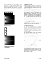
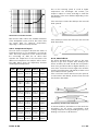
TI 323 (Version 6.0)
C4 System
Specifications and configurations
General Information
Technical Information TI 323
Version 6.0E, 03/2003, D5323.E.06
© by d&b audiotechnik AG 1995-2003; all rights reserved.
The information presented in this document is, to the best of our
knowledge, correct. We will however not be held responsible for the
consequences of any errors or omissions.
Technical specifications, weights and dimensions should always be
confirmed with d&b audiotechnik AG prior to inclusion in any
additional documentation.
d&b audiotechnik AG
Eugen-Adolff-Strasse 134, D-71522 Backnang
Telephone +49-7191-9669-0, Fax +49-7191-95 00 00
E-mail: [email protected], Internet: www.dbaudio.com
C-Series
A modular concept
The d&b audiotechnik C4 system has been
specifically optimized for flexible, modular array
configurations and high sound pressure levels.
Applications range from professional touring industry
use and large scale sound system installations, down
to single cabinet set ups requiring narrow dispersion
over a wide frequency range with minimum
dimensions. The "d&b specific" combination of a
natural, intelligible sound character that is clear and
transparent even at high sound pressure levels provides
the engineer with an efficient, effortless tool and a
neutral platform for the creative part of his work.
d&b's co-operation with MAN flying systems resulted in a
flexible mechanical structure for quick and easy set up of
array configurations with small footprints. All relevant
parts of the system have load safety factors type
approved to the German BGV C1 safety standard.
Software support for planning and calculating flown set
ups, regular safety checks, certification for mobile systems
and training seminars for practical handling aspects and
safety conscious use, all add up to complete the
mechanical concept of the C4 system. Centralized
computer set up, control and maintenance has been a
feature of d&b systems from the very beginning. All
mainframes can be networked via the d&b Remote
Interface Bridge (RIB), and with the addition of the d&b
ROPE software package user specific system control and
monitoring is accessible.
d&b is acutely aware that managing a rental business
puts tight requirements on the logistics and flexibility of a
system. Technically autonomous systems can be combined
and split in a wide variety of combinations. Light weight,
a compact size that takes into account standard truck
widths and modular packaging of the electronics all result
in time, space and cost benefits when commissioning and
transporting the system. In addition the full acoustical,
mechanical and electrical compatibility of all d&b systems
worldwide, results in high flexibility and availability when
scheduling events. This is d&b's system approach: all
loudspeakers, electronics, mechanics, design tools,
documentation and training, support and service are
designed and matched for the ease of the sound
designer, the system and balance engineer, the
warehouse manager and the system owner.
TI 323 (6.0E)
d&b systems are serious investments, however they excel
in return on investment versus total cost of ownership. For
medium to large scale sound reinforcement applications
the C3, C4-TOP and C4-SUB loudspeakers form the
basis of a modular, arrayable system, along with the
B2-SUB infrabass. The C3 is the line array module for
the C4 system. It distinguishes itself from conventional line
array concepts in several respects. First of all, with its
horizontal dispersion of 35°, it is meant to be part of a
larger array that can be precisely designed for the
specific horizontal and vertical coverage that is actually
required in an application. If necessary, it allows for
flawless horizontal coupling when wider coverage over
longer distances is needed. Secondly, it works as a 2 or 3
cabinet column within a C4 cluster, adding long throw
capability for the high end. And, last but not least, with its
unique wave front adapter that couples a total of three
1.3" exit drivers, it exhibits superbly controlled curved
coherent wavefronts up to 16 kHz at any vertical angle
between 1° and 5°. This also allows a full line array
approach without losing HF efficiency. Theoretical studies,
computer aided design and extensive practical tests led
to the influential, but unequalled coaxial horn-in-horn
design of the C4-TOP loudspeaker. It is the constant
directivity module of the C4 system and features an
exceptionally constant and narrow 35° x 35° dispersion
down to 700 Hz. The C4-SUB has been designed
specifically as the flown subwoofer in a C4 system. Its
frequency response extends down to 50 Hz, and its
cabinet shape, size and flying arrangements are totally
compatible with the C3 and C4-TOP. For extended low
frequency reproduction, the B2-SUB infrabass system is
used. The low end of the frequency range is produced
much more efficiently in a ground coupled configuration,
and for this reason there are no flying fittings on a B2
cabinet. Near field requirements can be met by the C7
and MAX systems. The C4 system and B2 are driven by
the P1200A and A1 mainframes respectively.
The following TI describes the loudspeakers and their
characteristics, system amplification, connections,
acoustical parameters, system design and the rigging
concept, devices and tools. It also contains examples of
proven system set ups of various sizes.
3 - 36
1. The loudspeakers and their characteristics
MAX
C7-TOP
85 Hz -18 kHz / 133 dB SPL*
60° conical
MAX is a passive full range system with a 15"/2"
coaxial driver. MAX is available with flying studplates
as an option and therefore can be integrated into
flown set ups as a dedicated C4 downfill. The shape
of the cabinet also allows horizontal arraying of
multiple MAX cabinets when used as a stacked near
field system. To ensure correct coherence with d&b
subwoofers it is recommended to use a P1200A fitted
with ampMAX (passive mode) or AMP/L modules.
68 Hz -18 kHz / 136 dB SPL*
75° horizontal x 40° vertical
The C7-TOP is equipped with a 15"/1.5" coaxially
mounted hornloaded driver combination in a vented
enclosure. The use of coaxial horns gives the C7-TOP
a controlled, even dispersion pattern from a compact
cabinet. The high output capability of the C7-TOP
allows it to operate in the most demanding PA
applications. With a horizontal dispersion of 75°
making it ideal to complete a C4 array covering mid
to near field areas and side seating tiers. In
combination with the C4-SUB, the C7-TOP must be
operated in CUT mode only.
Dimensions in mm [inch]
Weight: 26 kg/57 lb
Dimensions in mm [inch]
Weight (incl. wheels): 52 kg/117 lb
MAX dispersion characteristics**
* 1 m, free field; Broadband measurement, pink noise, crest factor 4,
peak measurement, linear weighting
** Dispersion angle vs frequency plotted using lines of equal sound pressure
(isobars) at –6 dB and –12 dB
TI 323 (6.0E)
4 - 36
C4-SUB
50 Hz - 150Hz / 133 dB SPL*
The C4-SUB uses a 18" driver in a compact bandpass
horn design. As a part of the C4 system, the C4-SUB is
designed to be used with the C4-TOP.
C7-TOP dispersion characteristics**
C4-TOP
150 Hz -18 kHz / 138 dB SPL*
35° horizontal x 35° vertical
The C4-TOP uses a 12"/2" driver combination in a
coaxial horn-in-horn design. The shape and acoustic
design (the use of CD horns) of C4-TOP cabinets enables
them to be arrayed for increased coverage. The high
output and long throw capabilities of the C4-TOP allows
coverage to 30 metres (98 ft) and beyond. The dedicated
C4-TOP controller module, incorporates a HFC circuit
(High Frequency Compensation) to make up for the high
frequency absorption of air over distance.
Dimensions in mm [inch]
Weight (incl. wheels): 48 kg/106 lb
C3
Dimensions in mm [inch]
Weight (incl. wheels): 58 kg/128 lb
130 Hz - 16 kHz1
(Standard mode) / >143dB SPL*
80 Hz - 16 kHz1
(LFC mode) / > 140 dB SPL*
35° horizontal x 5° vertical
The C3 is an active, biaxial speaker system, which consists
of two hornloaded 10" mid-range drivers and three 1.3"
compression drivers. The horizontal dispersion is the same
as the C4-TOP and therefore these cabinets can be
combined in an array with a standard horizontal splay of
the cabinets between 20° and 30°. Due to the narrow
vertical dispersion and the shape of the wavefront of the
C3, this cabinet extends the far field of the C4 array by
using cylindrical wavefront technology. The purpose of
the C3 is to cover the far field starting from 40 metres
(131 ft) and beyond. The dedicated C3 controller module
is designed to create a flat frequency response with two
cabinets and a vertical splay of 5°. The dedicated C3
controller module incorporates an HFC (High Frequency
Compensation) switch to compensates for the excessive
losses of the HF band over distances and a LFC (Low
Frequency Compensation) to shift the lower corner
frequency down to 100 Hz. This switch can be used for
speech reinforcement without additional subwoofers.
1
Two cabinets
Broadband measurement, pink noise, crest factor 4, peak measurement
linear weighting
** Dispersion angle vs frequency plotted using lines of equal sound pressure
(isobars) at –6 dB and –12 dB
*
C4-TOP dispersion characteristics**
TI 323 (6.0E)
5 - 36
B2-SUB
32 Hz - 68 Hz
(Infra mode) / 136 dB SPL*
37 Hz - 125 Hz
(Standard mode) / 139 dB SPL*
The B2-SUB uses two 18" drivers in a bandpass horn
design. In the examples discussed in this TI the B2-SUB is
used as an infrabass enhancement for C4 systems
(combined with C4-SUBs) and exclusively used in Infra
mode.
Dimensions in mm [inch]
Weight (incl. wheels): 71 kg/156 lb
Dimensions in mm [inch]
Weight (incl. wheels): 102 kg/225 lb
C3 horizontal dispersion characteristics**
* 1 m, free field; Broadband measurement, pink noise, crest factor 4,
peak measurement, linear weighting
** Dispersion angle vs frequency plotted using lines of equal sound pressure
(isobars) at –6 dB and –12 dB
TI 323 (6.0E)
6 - 36
2. System amplification
Suitable for use with all d&b C-Series systems, the
P1200A mainframe (2 x 600 W / 4 ohms) has
two front panel slots to accommodate one or two
loudspeaker specific controller modules. In the case of
the C4/C7 loudspeakers one channel of a P1200A
mainframe can drive up to two cabinets.
Single mainframes can be fitted with both TOP and
SUB modules to drive mid/high cabinets on one
channel and subwoofers on the other, two C4-TOP
and two C4-SUB loudspeakers can then be fed by a
single four core cable from the mainframe and
connected in a daisy chain.
Alternatively, single mainframes can be fitted with two
identical TOP or SUB controller modules to create
stereo mid/high or subwoofer systems.
C4-TOP
C4-SUB
CUT
100Hz
P1200A
PWR
HFA
TEMP
OVL
OVL
ISP
GR
PROT
ISP
MUTE
A
B
GR
MUTE
REM
0
0
LOCK
ON
REM
OFF
-6
+6
-12
dB
-6
+6
-12
dB
OUT CHANNEL A
FAIL
FUSE T2A
FUSE T8A
FAIL
220V-240V~
50-60 Hz
2200 W max
OVER
VOLTAGE
INPUT B
INPUT A
INPUT LINK
INPUT LINK
CAUTION
P1200A Mainframe
Weight: 22 kg / 49 lbs
REMOTE
CONTROL
Z2300000121236
OUT CHANNEL B
MONO OUT
Made in Germany
®
e-mail: [email protected]
Dimensions (HxWxD): 3 RU x 19“ x 13.9“
Weight: 22 kg/48.5 lb (with modules)
The C3 loudspeaker is a 2-way active design and
therefore requires both channels of a P1200A. Up to
two C3 loudspeakers can be driven by a P1200A
power amplifier fitted with the C3 controller module.
To avoid HF loss with long cable runs each cabinet
must be connected to one of the mainframe outputs
using separate cables with a minimum cunductor size
of 4 x 2.5 mm2 (13 AWG).
The A1 mainframe (1200 W/350 W/4 ohms) the
dedicated mainframe for d&b's active systems. Fitted
with a B2 controller module it drives the B2-SUB which
is used for infrabass enhancement of C4 systems. The
B2 controller also provides a filtered and buffered
low impedance output, the C4 OUT, that can be used
to drive C4 controllers when they are used in
combination with B2-SUBs.
PWR
TEMP
PROT AB
REM
REM
OFF
FUSE T2A
FAIL
B2
CAUTION
TI 323 (6.0E)
INPUT
RISK OF ELECTRIC SHOCK
DO NOT OPEN
INPUT LINK
FUSE T8A
220V-240V
50-60 Hz
2200 W max
FAIL
∼
P1200A Mainframe
Weight: 22 kg / 49 lbs
OVER
VOLTAGE
REMOTE
CONTROL
OUTPUT
Z2300000121236
Made in Germany
The modular nature of these individual systems lends
itself to the creation of customized sound
reinforcement designs which allow for future
expansion or reconfiguration when the need arises.
C4 OUT
LOCK
ON
PIN ASSIGNMENT
A
B
C
D
E
F
G
H
LOW OUT +
LOW OUT SPEAKER ID
SPEAKER ID
SENSE DRIVE +
SENSE DRIVE nc
nc
®
e-mail: [email protected]
Dimensions (HxWxD): 3 RU x 19“ x 13.9“
Weight: 22 kg/48.5 lb (with modules)
7 - 36
3. Connections
INPUT SIGNAL
NOTE: INPUT B is not used !
P1200A
C3
HFC
OUT 1
INPUT B
INPUT A
INPUT LINK
INPUT LINK
OV HI
LFC
OV LO
GR HI
GR LO
MUTE
d&b MC4
ISP
OUT 2
C3
MONO OUT
0
-6
+6
dB
-12
C3 CONTROLLER
d&b MC4
OUT 2
C3
OUT 1
C4-TOP
LINK OUT C4
d&b MC4
INPUT A
C4-TOP
P1200A
C4-SUB
HFA
INPUT B
OUT CHANNEL A
OVL
OVL
ISP
INPUT LINK
ISP
GR
C4-TOP
d&b MC4
INPUT A
LINK
INPUT LINK
C4-SUB
GR
MUTE
MUTE
OUT CHANNEL B
0
-6
0
+6
-12
MONO OUT
dB
-6
d&b MC4
+6
-12
dB
C4-TOP/C4-SUB
CONTROLLER
OUT CHANNEL B
d&b MC4
C4-SUB
INPUT SIGNAL
C4 OUT
B2
INFRA
A1
B2
C4 OUT
OV
ID
GR
MUTE
ISP
INPUT
INPUT LINK
OUTPUT
PIN ASSIGNMENT
A LOW OUT +
B LOW OUT -
0
-6
+6
C
D
E
F
G
SPEAKER ID
SPEAKER ID
SENSE DRIVE +
SENSE DRIVE nc
H nc
-12
dB
B2-SUB
CONTROLLER
OUTPUT
d&b MC8
B2-SUB
LINK OUT
FULLRANGE
TI 323 (6.0E)
8 - 36
3.1.
Line signal connection
Line level signal wiring needs much more care than most
people believe. In total there are three major factors to
consider:
− The output impedance and maximum output
current capability of the driving device.
− The length of all connecting cables.
− The total capacitance between the signal
conductors (between pins 2 and 3 of
corresponding XLR connectors).
The number of controller input channels that can be
connected in parallel is limited by their total impedance
and the output capabilities of the drive unit. Standard
balanced outputs of most signal processing equipment
are rated for load impedances of > 600 ohms while
each channel of a P1200A mainframe has an input
impedance of 44 kΩ.
Where multiple units of equal impedance are connected
in parallel, the aquivalent total load impedance is halved
with each doubling of the number of units connected. In
the case of the P1200A mainframes this would allow a
theoretical maximum of approximately 64 input channels
(32 dual channels of P1200A) to be connected to a
standard balanced output. To maintain full available
headroom, a standard 600 ohms rated output should not
be loaded with less than 2 kΩ (corresponding to 22
channels or 11 dual channels of P1200A). With most
output stages, anything less immediately results in a
drastic reduction of available headroom.
Extra care must be taken when low impedances are
driven via long multicore cables: the small capacitive
load of the cable is effectively paralleled to the receiving
inputs. Capacitive loads dramatically decrease drive
capabilities of most output stages due to additional phase
shifts caused by the low pass filter formed by the output
impedance and the capacitive load. As a rule of thumb,
not more than 12 channels (6 dual channels of P1200A)
should be connected in parallel to one 600 ohms rated
drive line via a multicore.
Where a large number of controllers have to be driven
with the same signal, especially via long cables, suitable
line drivers should be used and/or the system must be
subdivided using multiple outputs and signal lines.
The C4 OUT circuit of each B2 controller offers a very
low impedance line driving capability (actual output
impedance < 20 ohms), and can deliver full headroom
into virtually any load.
Tips:
Use the C4 OUT provided on an A1/B2 controller to
drive P1200A mainframes for C4 systems. The C4 OUT
provides a filtered and buffered signal to the C4
controllers and effectively limits the lower frequency
range of the C4-SUBs to 60 Hz. The frequencies below
60 Hz are efficiently covered by the B2s, while the C4SUBs can benefit from the extended headroom available.
TI 323 (6.0E)
Using the C4 OUT, with its low impedance line driving
capability, is also a useful way to avoid drive line
impedance problems in larger systems. Where failure of
an A1/B2 controller occurs, including loss of mains
power, the input signal is automatically switched by a
relay to provide a hardwired connection to the C4 OUT.
Do not use the MONO OUT of a mainframe to
overcome the problem of drive line impedance. The
MONO OUT provides a signal which is a –3 dB sum of
channel A and channel B. If you apply the same signal to
both channels their sum is +6 dB, the MONO OUT
signal in this case would be +3 dB. The resulting gain
structure within the system would be compromised with
controllers driven in this manner running at a higher level.
In large set ups where multiple B2 systems are fed from
separate auxiliary or matrix sends, independent from the
master send, C4 systems can be fed from one or more of
the A1/B2 controllers per side leaving the majority of B2
systems under independent control.
Be careful with digital equalizers: digital equalizers
always have a nominal delay (latency) of around 1 to 3
ms, even when their delay setting is on zero.
When using different drive lines for a system it is essential
to make sure that every channel used has the same delay
time, including taking into account the conversion delays
of any digital equalisers or other processing units.
Different delay times can have disasterous effects on
signal coherence; at its best this results in a loss of
acoustic energy, at its worst frequency dependant lobes
are created in various directions.
When using a ratio of more than one B2 to four
C4-SUBs, we suggest a reduction in the input level to the
B2s to maintain an even frequency response of the
overall system, while increasing the low frequency
headroom. If a lack of punch is observed, very often the
relative B2 level is simply too high. The "punchy" part of
the bass is in the frequency range handled by the C4SUB from around 70 to 150 Hz and therefore too much
B2 energy masks all direct percussive output signals.
3.2.
Speaker wiring
d&b recommends the use of high quality loudspeaker
cable of sufficient wire diameter. Do not be fooled by
tables presenting huge numbers in Watts of power loss
for a specific combination of wire diameter, load
impedance and cable length. A loss of 200 Watts or 20
% of the power, from 1000 Watts sounds a lot, but keep
in mind that this is approximately 1 dB in terms of level.
A 2.5 mm2 (10 AWG) cable is recommended in order to
keep the losses below 0.5 dB when connecting a 4 ohm
load over a distance of up to 30 metres (98.4 ft). If the
load is 8 ohm, the length can be doubled. If the distance
is greater, the wire diameter has to be increased.
9 - 36
3.3.
Mains power supply
requirements
Power consumption of amplifiers is dependent on many
factors including load impedance, signal level and signal
characteristics (speech, music). A key factor in estimating
amplifier power consumption is the crest factor (CF) of
the applied signal. The crest factor is a measure for the
ratio of peak to RMS voltage of a signal.
The table below shows the total average output power
and the corresponding power consumption of a P1200A
(the figures are similar for an A1), driving 4 ohm loads
(both channels) to the clipping point of both mainframe
power amplifiers.
Signal
CF
P out
Pin
1
1900 W
2600 W
Sinewave
1.4
1200 W
1830 W
Pinknoise/
compressed
music
3.5
200 W
500 W
Dynamic music
5
100 W
300 W
Speech/highly
dynamic music
8
40 W
200 W
Squarewave
In reality, even if the system is driven hard, with
compressed music, limiters engaged, the average power
consumption will hardly exceed 1000 Watts per
mainframe. Standard power supply ratings of
16 A/230 Volts allow up to 3 P1200A/A1 mainframes to
be connected. A single phase 32 A takes up to 6
mainframes etc. Standard power supply ratings of 30 A/
100-115 V can also accommodate 3 mainframes.
The built in soft start circuitry limits each mainframes
inrush peak current to 5 A/230 V (10 A/100-115 V). This
prevents circuit breakers from tripping.
TI 323 (6.0E)
10 - 36
4. Acoustical parameters
4.1.
Power and bandwidth
The C4 system (C3, C4-TOP and C4-SUB) is a flexible
modular sound reinforcement system.
The TOP/SUB ratio can be adapted to the power and
bandwidth required for the specific program material:
− speech only reproduction
2 x C4-TOP/1 x C4-SUB or
2 x C3 in LFC mode
− light music program
1 x1 C4-TOP/2 x C4-SUB or
2 x C3/4 x C4-SUB)
− full range music
4 x C3/4 x C4-SUB/1 x B2 or
4x C4-TOP/4 x C4-SUB/1 x B2
Modular hardware design and arrayability enable the
scaling of a system for any coverage and SPL
requirements.
4.2.
Level requirements
It is difficult to give a general recommendation on the
sound pressure level (SPL) needed for specific
applications. The suitability of a system is linked to a
number of factors such as the program material and the
nature of the acoustic environment - the size, shape and
surfaces of the room, loudspeaker and audience
positions etc. However, simple calculation can help clarify
which type and numbers of speakers are needed to
achieve a desired SPL at a defined distance.
The level produced by a loudspeaker system diminishes
with distance; the propagation loss in free field conditions
is –6 dB with each doubling of distance (known as the
Inverse Square Law see chapter 5. Sphere or Line ?). This
rule is also valid for line arrays since the 3 dB loss per
doubling of the distance happens only with straight line
sources.
A pair of speakers used left and right, as with a stereo
system, will raise the total SPL by an average of 3 dB in
their overlapping coverage (incoherent coupling). Given
a stereo system where an average direct 100 dB SPL is
required at the mix position 20 metres (65 ft) from stage,
then the level produced by each side of the system needs
to be 100 dB –3 dB +26 dB = 123 dB. An additional
12 dB of headroom should be allowed for the peak
levels of dynamic program. In this case a system capable
of producing 135 dB SPL per side should prove adequate
(coupling of multiple systems is described later).
TI 323 (6.0E)
distance
rel. level
2 m (6.5 ft)
– 6 dB
3 m (9.8 ft)
– 10 dB
5 m (16 ft)
– 14 dB
10 m (33 ft)
– 20 dB
20 m (65 ft)
– 26 dB
30 m (98 ft)
– 30 dB
40 m (131 ft)
– 32 dB
80 m (262 ft)
– 38 dB
4.3.
Coverage
The coverage is a decisive criteria for the perception
of the quality of a sound reinforcement system.
Naturally, the system coverage pattern needs to be
sufficiently wide to take in the entire audience
(Democracy for Listeners). Narrow coverage systems
can be arrayed to provide wider coverage. This
works well, provided the systems used have a well
defined constant directivity (CD) characteristic and
can be physically arrayed at the optimum relative
angle.
On the other hand it is important to reduce the
diffuse sound by limiting the coverage angle of the
system to audience areas only. The diffuse sound
energy in a room remains largely constant whereas
the direct sound energy from the loudspeakers
diminishes with distance. Narrow coverage systems
produce less diffuse sound energy and therefore
provide a higher direct to diffuse level ratio at
greater distance. This maintains a higher intelligibility
and is often described as a greater 'throw'.
The three following illustrations, created in an acoustic
simulation program, show the differences in the
coverage of a listening area using wide, medium and
narrow dispersion loudspeakers. In each simulation
two stereo cabinets cover a listening area 20 m (65 ft)
wide by 25 m (82 ft) long. The coverage angles, which
decrease from the left, are 90° x 50°, 60° x 40°, 35° x
35°. All are at equal level in the audience area right
in front of the speakers.
11 - 36
One can easily see, that the narrow dispersion
cabinets give greater throw and higher levels towards
the far field, but are compromised by uneven near
field coverage.
Sound pressure coverage of 90°x50°, 60°x40° and
35°x35° system
Speech intelligibility is also influenced by the
variations in loudspeaker coverage. The second
illustration is a plot of the Speech Transmission Index
(STI) over the listening area used in the previous
illustrations. There are very clear differences in speech
intelligibility; white and light grey show the areas of
high intelligibility. As the coverage of the
loudspeakers narrows, speech intelligibility quite
clearly improves in the far field.
4.4.2. Horizontal coverage
The horizontal coverage angle of the loudspeakers
should not be wider than is necessary to cover the
audience area. Sound radiated in other directions
adds energy into the diffuse sound field, which will
decrease intelligibility.
The angled rear side panels (15°/C4/C3 and 25°/
C7-TOP) indicate the horizontal arraying angle of the
loudspeaker. Using these angles it is possible to verify
the nominal horizontal coverage visually from behind
the cabinet.
If a single system does not provide enough coverage,
more cabinets can be put together in an array. This
requires that systems have good constant directivity
characteristics in order to keep the overlap regions as
small as possible and also not leave any coverage
gaps.
4.4.3. Coupling of multiple systems
If, for example, a horizontal coverage of 90° is required,
it can be achieved with a single 90° system, or with three
35° degree systems with a 30° angle between each
cabinet. The latter solution clearly gives more sound
pressure and a much sharper level drop at the edges of
the coverage area. The sharp level drop at the edges is
a very valuable effect when working in highly
reverberant environments, since the amount of energy
wasted into the diffuse field is dramatically reduced.
Excellent constant directivity properties of a single system
are essential to enable the creation of array solutions.
When arraying C3 or C4-TOP systems at 30°/ C7-TOPs
at 50°, an extremely smooth overlap with minimal
interference is ensured (see isobar plots in chapter 1).
STI (Speech Transmission Index) of 90°x50°, 60°x40° and
35°x35° system
4.4.
Speaker placement considerations
4.4.1. Vertical coverage
The vertical aiming of a cabinet, the height and the
angle, largely determines the sound level distribution
from the source to the back of the room. To achieve the
best coverage requires that the speaker height and angle
are set independently. Placing the loudspeakers too low
and too close to an audience will give high level near
field at the expense of inadequate far field coverage.
Higher speaker placement will produce more even
audience coverage from the front of the stage to the
back of the room.
Particularly in smaller venues, a speaker placed too high
directs too much energy towards the back of the room
where it can reflect off the rear wall. This will create a
diffuse sound and ruin intelligibility by reducing the ratio
of direct to reflected energy. It may also generate a very
audible 'slap' echo. Simply tilting the speakers down and
aiming them towards the audience can prevent these
effects.
35
90
35
35
-6 dB
-45
0
+45
diffuse sound
-6 dB
-45
0
+45
Comparison of a single 90° coverage cabinet with
a 3-wide array of 35° systems
TI 323 (6.0E)
12 - 36
4.4.4. Comb filter effects
With more than one system per side care has to be taken
to minimise the audible influence of the comb filter effect.
An unavoidable problem with multiple sound sources, this
effect creates a very uneven frequency response with
audible peaks and cancellations due to interference
across the coverage area.
What is a comb filter and how does it build up ?
If identical signals from two sources reach a point with a
small offset in time, there is always a frequency for which
this offset difference corresponds to the time for half of
its wavelength. This signal arrives at the listening point
twice, but with opposite phase. The result is a full
cancellation for this frequency.
Two times this frequency is called the comb filter
frequency fcomb for this point. The result is an in-phase
arrival and, given equal levels, a +6 dB addition.
At 1.5 times fcomb there will be another cancellation and
so on.
In the example above two sources of equal level and a
time difference of 1ms are added.
1ms corresponds to a full cycle at fcomb = 1 kHz. 1/2
fcomb = 500 Hz, corresponding to half a cycle difference
in time, at this frequency we see the first cancellation. In
frequency steps of fcomb = 1000 Hz starting from 1/2
fcomb we get more cancellations.
If the levels of the sources is different, the effect stays the
same, only the depth of the cancellations decreases.
To minimise comb filter effects, the mid/high cabinets are
arrayed in such a way that the coverage patterns of the
loudspeakers overlap as little as possible. Arraying C3
TI 323 (6.0E)
and/or C4 cabinets using the angled rear side panels
produces minimal overlap and minimal interference with
maximum uniformity of frequency response over the
horizontal dispersion angle.
If a system has insufficient throw for a certain direction in
a room, multiple cabinets covering the same area can be
stacked vertically. This minimises audible comb filter
effects at audience level.
The cabinets should be placed as close together as
possible, high enough and angled correctly to cover the
far field only. Given that the difference in distance
between the sources is rather small, filter effects are
limited to very high frequencies.
Summary:
Source overlapping is acceptable in the far field because
with greater distances the relative differences in path
length become smaller thus minimising audible comb filter
effects. The benefit is an increased SPL. Try to limit
overlapping to the vertical plane which limits the areas
covered by multiple speakers to the far field. Speakers
covering the same area should be positioned as close
together as possible in order to keep the path length
distances low.
In contrast, horizontal overlapping in an array will also
produce overlapping coverage in the near field. This
causes highly audible comb filter effects starting in the
mid frequency band and gives an increase in SPL where
it is not needed.
4.4.5. Coherent signals and directivity
build up
If identical signals, reproduced by different sources,
arrive at a point without a time difference, these
signals are called coherent.
If there is a small time difference, such that for the
highest frequency of the source's operating band the
time for half a cycle is still much longer than the
difference in arrival time, these two sources are also
summed coherently. This means that a doubling of the
number of sources will result in a +6 dB level
increase.
This effect can be utilized for subwoofers located
close together, these will sum below a certain
frequency, dependent on the total size of the
subwoofer stack.
With a few subwoofers stacked together the
increased level radiates spherically, so in all
directions. Larger arrays will produce directivity
patterns: a vertical column of subwoofers will add
coherently in the horizontal plane, a horizontal line
will add coherently in the vertical plane. As the
listening point moves from this plane, coherency will
decrease until maximum cancellation occurs.
It is only possible to direct low frequency energy by
stacking subwoofers in columns. Horizontal subwoofer
arrays are normally not desirable; they narrow the
13 - 36
horizontal dispersion while still radiating a huge
amount of LF energy vertically. Vertical arrays
behave more practically; they maintain a broad
horizontal dispersion while narrowing the vertical
pattern. A vertical array puts more energy into
standard audience areas than a horizontal line of
subwoofers.
4.4.6. Rule of thumb
Doubling the number of subwoofers per side will give
an additional 6 dB in the low end. However, when
doubling mid/high systems (radiating into the same
direction) the average gain in their frequency range
will be around 3 dB.
For this reason there is usually a difference in ratio
between TOPs and SUBs; smaller systems 1 x TOP/2 x
SUB ratio up to a 1 to 1 ratio for bigger set ups.
All these theoretical aspects can be applied in the
following array design considerations: every sound
design that requires more than one cabinet, either for
SPL, or for coverage reasons, or a combination of
both, is a trade off between comb filter effects, the
resulting SPL over the audience area and as a further
result of the above, uniformity of frequency response.
The Democracy for Listeners.
4.5.
Atmospheric effects
The propagation of a sound wave depends on the
properties of the atmosphere, these effects are
difficult to predict due to their chaotic behaviour.
Subwoofer array for maximum
horizontal directivity
4.5.1. Excessive HF loss
The effect of atmospheric loss is frequency
dependant. With increasing frequency the transfer of
energy decreases, this behaviour also depends on
temperature and relative humidity. As a rule of
thumb, the loss is greater with decreasing temperature
and relative humidity.
The following diagram shows the frequency
dependant attenuation at 100 metres (328.1 ft), 20° C
with 10 %, 20 % and 50 % relative humidity.
Subwoofer array for maximum
Loss over frequency at 100 metres (328.1 ft) with 10 %,
vertical directivity
20 % and 50 % humidity
The C4-TOP and C3 controller provide a function
switch HFC (High Frequency Compensation) that
compensates for this transmission loss at 30 metres
(98.4 ft) and 50 % humidity.
TI 323 (6.0E)
14 - 36
6
Due to the increasing speed of sound at higher
temperatures the wavelength will increase (see
chapter 5. Sphere or Line?). According to Snell's law
the direction of the wave will bend depending on the
thermal layers.
dB
4
2
If the warm layer is below the cold layer the wave will
bend upwards.
0
-2
-4
20
100
1k
10k
20k
HFC function of a C4-TOP controller
Note that this filter reduces the available headroom
of the loudspeaker system, and for this reason there
are certain limits for electronic compensation,
depending on distance and required SPL.
4.5.2. Temperature layers
The most obvious example to illustrate the effects of
temperature layers in our atmosphere is an open-air
show. The body temperature of the audience heats
the surrounding air, while the air above them
maintains the temperature of the environment. The
difference in temperature can easily be 10°C or more.
The table below shows the dependency between
wavelength and temperature.
f (Hz)
λ (10°C)
λ (20°C)
λ (30°C)
λ (40°C)
31
10.87 m
35.66 ft
11.06 m
36.27 ft
11.26 m
36.94 ft
11.45 m
37.57 ft
63
5.35 m
17.55 ft
5.44 m
17.85 ft
5.54 m
18.18 ft
5.63 m
18.47 ft
125
2.70 m
8.86 ft
2.74 m
8.99 ft
2.79 m
9.15 ft
2.84 m
9.32 ft
250
1.35 m
4.43 ft
1.37 m
4.49 ft
1.40 m
4.59 ft
1.42 m
4.66 ft
500
64.40 cm
2.113 ft
68.60 cm
2.251 ft
69.80 cm
2.290 ft
71.00 cm
2.329 ft
1000
33.70 cm
1.106 ft
34.30 cm
1.125 ft
34.90 cm
1.145 ft
35.50 cm
1.165 ft
2000
16.85 cm
0.553 ft
17.15 cm
0.563 ft
17.45 cm
0.573 ft
17.75 cm
0.582 ft
4000
8.43 cm
0.277 ft
8.58 cm
0.282 ft
8.73 cm
0.286 ft
8.88 cm
0.291 ft
8000
4.21 cm
0.138 ft
4.29 cm
0.141 ft
4.36 cm
0.143 ft
4.44 cm
0.146 ft
16000
2.11 cm
0.069 ft
2.14 cm
0.070 ft
2.18 cm
0.072 ft
2.22 cm
0.073 ft
TI 323 (6.0E)
If the cold layer is below the warm layer the wave will
bend downwards.
4.5.3. Wind effects
The effects described above are more or less static,
however it gets more complex when looking at the
effects caused by the wind. Usually the wind speed is
lower near ground level than at higher altitudes, as a
result if the sound wave travels against the wind the
speed of sound decreases with altitude, and the sound
wave will then be bent upwards.
If the sound wave travels with the wind, the speed of
sound increases with altitude, and the sound wave will
then be bent downwards.
Refraction by variation of the wind speed
As mentioned before, the behaviour of the wind in the
atmosphere can be erratic. Unpredictable winds
creating whirlpools of rising and falling air may occur,
bending sound waves in all directions.
15 - 36
5. Sphere or line ?
This chapter investigates the differences between
spherical and line sources.
5.1.
As any loudspeaker has a maximum SPL capability, it
maybe necessary to use a quantity of loudspeakers in
order to increase the SPL over greater distances.
Spherical sources
An ideal spherical source is an infinitely small point.
Energy radiated from such a point source is
distributed spherically. Doubling the distance from the
source quadruples the surface of the sphere, while the
total acoustic power remains constant, therefore the
acoustic power density is quartered and the sound
pressure level is halved.
A
4A
Point
source
R
2R
In other words, the sound pressure level drops 6 dB
by doubling the distance from the source, this
behaviour is known as the Inverse Square Law.
This behaviour is valid not only for ideal spheres, it is
valid for all radiators where both the horizontal and
vertical angle diverge.
With this knowledge it is possible to calculate the SPL
for a specific loudspeaker at a given distance (D).
Usually the SPL of a loudspeaker is defined at a
distance of 1 metres (3.3 ft) on axis, therefore the
level drop can be calculated using the following
formula:
D
SPL(D )= SPL(1m)- 20log
1m
TI 323 (6.0E)
5.1.1. Combining spherical sources
Combining spherical sources to obtain various
horizontal and vertical dispersion patterns requires
loudspeakers that perform in a very specific manner.
Placing spherical loudspeakers adjacent to each other
always causes interactions between the sources.
These interactions are known as comb filter effects
and are described in chapter 4. To minimize the
comb filter effects the loudspeakers must produce
precisely controlled dispersion patterns. Splaying the
cabinets to match the –6dB isobars results in minimum
overlap and therefore minimizes the areas affected
by comb filter effects. Usually the spread of the
cabinets to the maximum possible angle can be
obtained in the horizontal plane, where a very even
energy distribution is essential. In the vertical plane it
might be necessary to adjust the angle between the
cabinets to suit the distance that has to be covered. A
large vertical overlap is used between a number of
boxes for the far field, while in the near field the
vertical overlap decreases and a single speaker will
provide sufficient coverage.
It is not possible to achieve a coherent coupling
between spherical sources, especially in the HF region,
as the distance between the acoustic centres is too
great. A coherent addition of two loudspeakers is
only possible on the axis between cabinets where
both path lengths are equidistant.
5.1.2. Signal tuning
Due to their directional behaviour, arrayed spherical
sources can be seen as single, independent
components, addressing a defined part of the listener
area. Coupling only happens with adjacent cabinets,
below the frequency of defined directivity. Depending
on the amount and arrangement of the individual
cabinets a shelf filter can be applied to compensate
this coupling effect.
16 - 36
5.2.
Line Sources
Line sources are nothing new; in the 50s it was the
only economical solution to build loudspeaker systems
that provided a specific directivity in a defined
frequency range. Without being aware, this
technology is often used today to increase the
directional behaviour of loudspeaker arrays.
The ideal line source is an infinitely long, continuous
radiator. Energy radiated from a line source is
distributed cylindrically, doubling the distance from
the source doubles the surface of the cylinder.
Therefore, the acoustic power density is halved and
according to power distribution the resulting SPL is the
√2 or –3 dB by doubling the distance.
To transmit 10 kHz (λ = 0,034 metre / 0.11 ft) the
distance between the drivers must be 3 cm or less. As
soon as the wavelength is shorter than the distance
between them the array creates side lobes and loses
its directional behaviour.
A
Line
source
2A
Simulation of the directional behaviour of a discrete line
array. Note the lobes where the wavelength is shorter
than the distance [d] between the drivers
R
2R
In reality continuous and infinite line sources do not
exist, and therefore a number of limitations should be
taken into account when predicting the behaviour of
a real line array.
Directional sources:
The second variation uses directional sources to
create a wave front that curves slightly and this is the
most common approach used in todays line arrays.
The wave front radius of each single source is
important to minimize the wave front offset between
sources.
5.2.1. Discrete line array
A discrete line array consists of a number of drivers
arrayed in a line, of which there are two variations.
Sperical sources:
The first is an array built out of spherical sources.
Because of their physical size there will be a spacing
between the acoustical centre of the drivers, and this
distance must be smaller than the shortest transmitted
wavelength.
The wavelength is calculated by:
λ=
c
f
Where:
λ = wavelength (m)
c = speed of sound (m/s)
f = frequency (1/s)
TI 323 (6.0E)
If the wave front offset [∆
∆x] is larger than λ/4, the
resulting wave front breaks up and loses its directional
property.
The flatter the wave front the higher the frequency
that can be transmitted.
Using magnetostatic or electrostatic ribbon drivers
can improve the behaviour for very high frequencies
however at the cost of efficiency, and it is for this
reason that these types of drivers are very rarely
found in professional sound reinforcement products.
17 - 36
5.2.2. Finite line arrays
The length of an array has a large impact on its
properties, and due to the finite length of an array
the initially cylindrical wave transforms into a
spherical wave. This near field/far field transition
radius is dependant on the length of the array and
the frequency being produced. This radius can be
calculated using the following rough formula:
l.f
2. c
2
rnear =
Where:
rnear = near field/far field transition radius (m (ft))
l = length of the array (m (ft))
f = frequency (1/s)
c = speed of sound (m/s)
5.2.3. Curved line source
The discussion so far has only covered situations
where arrays are set up in one straight line with no
vertical angle set between the loudspeaker cabinets.
In a typical real life situation a straight line set up will
not produce sufficient coverage in the vertical plane
and this requires improvement. The easiest way to
achieve this is to arrange the boxes in an arc, all with
the same vertical splay.
The first thing to recognize is the usual 6 dB level
drop per doubling of distance. As described in the
spherical sources section, the wave front now diverges
horizontally and vertically, exhibiting the behaviour of
a spherical source. The energy for the far field can
now be adjusted by changing the overall vertical
angle, halving the angle between cabinets increases
the energy in the far field (and only there) by 3 dB.
The table below shows the transition distance for a
5 metre (16.4 ft) long array at various frequencies.
f
r in m (ft)
100 Hz
3.7 m (12 ft)
1 kHz
37 m (121.4 ft)
10 kHz
370 m (1214 ft)
The result at high frequencies is a level drop of 3 dB
per doubling the distance. In other words this
behaviour shows that a line array works optimally in
the far field where all sources of the array arrive with
minimal path length differences, and where the
maximum coherent addition of sound energy occurs.
Close to the array the path length differences are
greater, leading to an increased incoherent addition
of the sound energy radiated by the array.
Comparing the line source with a spherical source
radiating the same energy shows that the 3 dB level
drop comes from a lack of energy close to the array.
At very low frequencies a line array behaves in the
same way as a normal spherical source.
TI 323 (6.0E)
5.2.4. J-shaped line source
A J-shaped array allows adjustment to the amount of
energy according to the distance that has to be
covered. This means no more than the number of
cabinets targeting the listener area is proportional to
the distance.
18 - 36
5.2.5. Signal tuning
Due to their frequency dependant coupling, curved or
J-shaped line arrays require a set up related filter.
The reason for this can be explained by considering
the wavelength. Coherent coupling occurs when the
transmitted wavelength is larger than the radiating
source. It is easy to see that everywhere in the
audience area the entire array combines to provide
the lower frequencies, whilst at higher frequencies
only a single source provides energy at any point in
the listener area. The usual way to compensate for
this effect is by introducing a low shelf filter, where
the corner frequency and attenuation depend on the
size and the total vertical dispersion angle of the
array.
TI 323 (6.0E)
19 - 36
6. System design
6.1.
Basic planing
The first consideration is the combination of horizontal
and vertical dispersion angles needed to cover the
audience area from specific positions. These positions
should be chosen so that the system can give an
acoustic orientation towards the stage for as many
listeners as possible, while avoiding directing energy
at close boundaries or recessed areas.
6.1.1. Step 1:
First, the total horizontal coverage angle has to be
defined. Above a certain venue size it is
recommended to check the far field and the mid to
near field coverage requirements independently.
From this rough overview the number and the aiming
of 30° sectors can be determined. The coverage
angle per column for C4-TOPs and C3s should be in
the range between 20° and 30°, however choosing
30° sectors results in a seamless, interference free
horizontal overlap between columns (50° sectors for
C7-TOP columns).
In the following example of a typical arena, far field
horizontal coverage is needed for sectors 2 and 3.
Mid field coverage is needed for all five sectors. Near
field coverage has to be provided for sectors 1, 2
and 3.
Far field coverage in sector 1 should be avoided,
since the target area will also be covered by the long
throw component of the other main PA cluster. Due to
the large difference in the path length to this area
from each cluster a high level far field coverage for
sector 1 would cause a second arrival, or echo and
therefore decrease intelligibility dramatically.
Depending on the source program and the chosen
loudspeaker type, either a 5-wide or a 6-wide set up
with an additional column of SUBs to increase LF
throw would be suitable.
6.1.2. Step 2:
The audience areas vertical coverage profile and
throw distances have to be calculated, if necessary
independently for every column specified in step 1. To
achieve a uniform coverage and direct to diffuse
sound ratio the SPL variation should not exceed
± 3 dB over the listener area. If, for instance, the
distance to the farthest listener is 60 metres (196.9 ft)
and the distance to the closest listener is about
8 metres (26.2 ft), depending on the height of the
cluster, the resulting level difference is 17 dB.
Example of a vertical profile with the main axis of the
TOP loudspeakers.
1
Stage
2
5
4
3
Typical arena situation, showing the necessary horizontal
coverage.
TI 323 (6.0E)
Depending on the type of event, the average SPL can
be defined. From this, the type, number and vertical
angle of the cabinets can be determined. Using the
Inverse Square Law and the level increase due to
coupling, the SPL for various areas and the relative
levels within the columns can be estimated. The result
is a defined array of either C3 and/or C4-TOP
cabinets for the vertical coverage per sector. In the
example shown, sectors 2 and 3 use five C3 for far/
mid field coverage with 0°, 1°, 3.5°, 6°, 11° and C4TOP with 21° vertical down tilt. The column for sector
1 should not cover the far field, so the uppermost
TOP cabinet is deployed with a –10° vertical down tilt
to cover the back of the ground floor.
20 - 36
Referring to set up examples 8 or 9, described later in
chapter 9, a modification of the column for sector 1
could be SUB-SUB-C3-C3-SUB-C4 (from top to
bottom), the other columns stay as shown.
6.1.3. Sidefills, backfills, downfills and
frontfills
Additional systems are needed to cover critical areas
such as directly in front of a stage, or side seating
tiers. For these areas it is essential to maintain total
system integrity and sound character. C7-TOP or
MAX fullfill this requirement as shown in the examples
later in chapter 9.
Sidefill and backfill systems cover the areas beneath
or behind the stage. In most cases these are located
near to the stage, are rather steep tiers or galleries
and need shorter throw and wider coverage angles
than the main system.
Frontfill systems cover the area directly in front of the
stage, the benefit is a better acoustic orientation and
intelligibility in the front rows.
If the set design does not allow frontfill systems,
downfills can be used to cover the area directly below
the main arrays and the front of stage. MAX can be
used as a complementary downfill to C3/C4/C7
systems in this situation.
6.1.4. Delay systems
There are two applications for delay systems:
Firstly, to increase the direct to reverberant ratio in
areas under balconies, or behind pillars. These are
usually smaller speakers that restore the high
frequency range within a mostly low and mid
reverberant field.
The other application is to support the main system
over large distances. For indoor situations their
purpose is to enable the main system to run at a
lower level or to maintain sufficient direct to
reverberant ratio in acoustically difficult situations, for
example when there are low or reflective ceilings. In
larger outdoor situations it is quite common to use
delayed systems that are similar to the main systems
and can deliver full energy to specific areas.
For indoor and outdoor purposes there are a few
basic recommendations:
Keep the horizontal coverage angle of the single
delay system narrow, 60° should be considered as a
maximum. Using wide angles creates time offsets
within the coverage area that are too large and
intelligibility will suffer dramatically.
Delay systems should offer directivity control to as low
a frequency as possible.
The omnidirectional lower frequency range will spill in
all directions and be audible beneath and behind the
delay system. It can also be advantageous to reduce
the level of a delayed full range system below the
frequency of its directivity control (LF roll off). Even
TI 323 (6.0E)
when using a delay system, almost the entire bass
energy has to be provided by the main system. Use
your ears.
Delayed systems should be placed as close as possible
to their target area, so their level and coverage can
be kept under control.
6.1.5. System tuning
Depending on the kind of system, signal processing is
required to achieve a proper sound quality.
Important:
Any kind of signal processing just affects the
loudspeaker. The rooms properties can not be
changed!
Do not try to create a flat frequency response. Due to
room acoustics a useful response would look similar
the graph below.
1°
2.5°
5°
Target frequency response
21 - 36
6.2.
Arraying C3 and C4 cabinets
6.2.1. Vertical array of C3 cabinets
A vertical array of C3 cabinets produces a precisely
shaped wave front following the mechanical
arrangement of the cabinets. The cutoff at the upper
and lower limits of the vertical dispersion of a C3
column is very sharp, and therefore precise aiming is
absolutely essential to address the desired audience
area. The vertical coverage angle of a single cabinet
is 5° and this defines the maximum splay angle
between adjacent cabinets in a column. This
dispersion angle is achieved above approximately 5
kHz, while lower frequencies will disperse into a wider
area creating an overlap of the coverage patterns of
the single cabinets. Therefore, directivity and the level
of lower frequencies increases with every cabinet
added to the column. Two cabinets arrayed vertically
with a 5° splay angle produce a flat frequency
response. Longer columns will therefore boost low
and low/mid frequencies according to the graph
below.
15
10
6
5
4
3
2
5
0
-5
20
100
1k
10k
20k
Typical change in frequency response
with increasing column length
(2, 3, 4, 5 and 6 deep)
This behaviour can be compensated by using a
standard 2nd order (12 dB) low shelf filter. The corner
frequency and gain setting depend on the number of
C3 cabinets in the longest column and on the overall
array size. Typical corner frequencies are listed in the
table below; the gain listed applies to a single column.
Longest C3
column in
array
Low shelf
fc
Gain
dB
3
800 Hz
–3
4
600 Hz
–4
5
450 Hz
–5
6
350 Hz
–6
7
250 Hz
–7
8
200 Hz
–8
Table of low shelf parameters for a single column
TI 323 (6.0E)
This equalization has to be used for the C3s only. C4TOP cabinets in the array should be driven from a
separate input signal feed. Decreasing the splay angle
to 2.5° or even 1° will also create an overlap of the
coverage patterns above 5 kHz resulting in increased
high frequency output to the main axis. This effect can
be used to scale the energy according to the distance
and to compensate for air absorption effects when
covering remote audience areas.
15
10
1°
5
2.5°
5°
0
-5
20
100
1k
10k
20k
Typical change in frequency response when decreasing
the splay angle between two cabinets from 5° to 2.5°
and 1°.
This mechanical HFC equalization as opposed to the
HFC circuit of the controller does not affect the
headroom of the system. To achieve a smooth level
distribution the vertical splay of a column is the first
thing to consider when designing a set up for a
specific venue. Usually the distances to the audience
that an array has to cover increase from the bottom
to the top of a column, consequently more power is
required at the top. This can be achieved by using
different vertical splay angles between cabinets in a
column, with smaller angles achieving more power
within a given vertical segment. For a smooth level
distribution over distance it is desirable to gradually
change the angle increments, e.g. 1°, –2.5°, –5° for a
4 deep column.
6.2.2. Vertical array of C3 and C4 cabinets
As their horizontal dispersion behaviour is identical,
C4-TOP and C3 cabinets can be easily combined in
one array. The larger vertical dispersion of a C4-TOP
can be used efficiently to cover the near field in front
of a C3 column. A vertical splay of 5° or 10° to the
lowest C3 is useful, depending on the total height of
the system.
6.2.3. Horizontal array of C3 and C4
cabinets
The horizontal angle between adjacent C3 and/or C4
cabinets in an array can be set to between 20° and
30°. The most even and widest energy distribution is
achieved with 30°. Smaller angles between the
cabinets will give a smaller horizontal coverage area
but will produce higher sound pressure on the centre
axis of the array.
22 - 36
The configuration of any array should be thoroughly
adapted to the actual venue room acoustics and
requirements. In order to keep diffuse sound low, the
total coverage angle should only be as wide as
necessary to cover the audience area.
C3-CO
C3-CO
Array EQ
Input signal
6.2.4. Operation with C4-SUB and B2-SUB
To extend the C3 frequency response C4-SUBs should
be used. Forming columns of SUB cabinets improves
efficiency and vertical directivity at low frequencies.
For a balanced sound at high levels a ratio of at least
one C4-SUB per C3 or C4-TOP cabinet is required.
For a further extension of bandwidth and headroom
ground stacked B2 subwoofers are used (INFRA
mode).
6.2.5. Time alignment and signal
distribution
When combining C3s and C4-TOPs the correct time
alignment of both systems is of great importance. To
achieve this C3 and C4-TOPs have to be driven with
separate signals. With a delay of 0.3 ms in the C4
signal path both systems are perfectly coherent over
the whole audio band. To avoid the influence of
different latencies (inherent delays) of the signal
chains, make sure that the C3s and C4s in one array
are driven with the same signal processing devices
using different outputs.
System EQ
Digital equalizer
0.3 ms
Delay
C4-TOP/SUB-CO
C4-OUT
B2-CO
C3 wiring with C4-TOP, C4-SUB and B2-SUB
For a set up with C3s and C4-SUBs in a cluster
without C4-TOPs no delay is required. Due to the low
shelf filter applied to the C3 a separate signal line
feeding the C4-SUBs is needed. Be aware to feed the
C4-SUBs from the same digital device to maintain a
common latency.
C3-CO
C3-CO
Array EQ
Input signal
System EQ
C4-SUB-CO
C3-CO
Digital equalizer
Bass EQ
C4-SUB-CO
C3-CO
Array EQ
C4-TOP/SUB-CO
C3 wiring with C4-SUB
Input signal
System EQ
Digital equalizer
0.3 ms
Delay
C4-TOP/SUB-CO
C4-TOP/SUB-CO
C3 wiring with C4-TOP and C4-SUB
Normally C4-SUBs will be driven from the same signal
processor output as the C4-TOPs, or if B2-SUBs are
used, from the C4-OUT of the B2 controller. Should
the B2-SUBs be driven separately (e.g. when driven
from an auxiliary output of the console or for time
alignment reasons), the low cut provided by the C4OUT of the B2 controller can also be created for the
C4 using a standard parametric bandpass filter in a
signal processor. The parameters are f = 44 Hz,
Q = 3, Gain = –6 dB.
TI 323 (6.0E)
6.2.6. Integration into the
C4 flying system
The vertical splays between the cabinets of a C4
array are set by load chains of different lengths. d&b
offer chains for 1°, 2.5° and 5° angles plus a
shortening chain enabling variable angles. For a
coherent coupling of adjacent cabinets the precise
alignment of the rear panels of the cabinets is
essential. Therefore it is necessary to use the d&b
Z5110.100 Hinge between the cabinets throughout
the whole column. C3 arrays have a very high vertical
directivity, therefore the use of a precise digital angle
finder to verify the desired aiming is strongly
recommended. Deviations of less than 1° can have an
immense impact on the coverage in the far field. A
laser distance finder is recommended to set the
correct array height.
23 - 36
7. Rigging concept and devices
The d&b flying system provides flexibility for scaling a
complete C3/C4/C7 sound reinforcement system. The
flying system is designed to aim and position the
loudspeaker cabinets in a way that ensures an
optimized acoustic result.
All d&b flying hardware is Type Approved to the
German safety regulation BGV C1.
7.1.
7.1.3. Ratchet strap
The ratchet strap is used to set the vertical angle of
the loudspeaker column. It is not a load bearing
component in the whole assembly. d&b offers 2 ton,
12 m (39 ft) straps for columns up to 8 cabinets deep.
The components
7.1.1. MAN Flying stud and CF4 Stud plate
C3, C4-TOP, C4-SUB, C7-TOP and (optionally) MAX
cabinets are fitted with MAN CF4 stud plates which
are designed to take the MAN Flying stud. The MAN
Flying stud (also called the D-Ring) is the central
component of the flying system. It is an easy to fit,
self-locking device which connects the cabinet to the
load bearing chains.
MAN Flying stud & CF4 Stud plate
7.1.2. Load bearing chains
According to BGV C1, the maximum allowed load is
560 kg (1234 lb) which is approximately the weight of
8 x C4 and 1 x MAX or 8 x C3 cabinets, including
fittings.
The chains are available in different lengths:
− 11-link chains are used to suspend a loudspeaker
column from a sub bar.
− 23-link chains are used to fly cabinets with a
vertical angle between them of approximately 5°.
23-link chains are also recommended for use as
top chains (sub bar to the top cabinet) for 6-8
deep columns.
− 1° chains are used to connect cabinets either to
gain space between the columns or to couple C3s
for the far field.
− 2.5° chains are the next angle increment to C3
cabinets.
− 47-link shortening chains (left and right versions),
are used to adjust the vertical angle between
cabinets in 5° increments.
TI 323 (6.0E)
Chains and rached strap
7.1.4. Hinge set
The hinge fits to the rear of the cabinets in a column
to maintain the alignment. It has a recessed slot to
accommodate a ratchet strap that speeds up rigging.
The hinge set can be retrofitted to all existing C3, C4
(402)-TOP, C4 (402)-SUB and C7 (702)-TOP cabinets.
It also can be used in ground stack situation to stop
cabinets from moving.
Hinge in a lashed column
24 - 36
7.2.
d&b flying hardware / cradles
7.2.1. d&b Installer
The Installer is a modular flying system mainly for
permanent installation or touring use where the
setting does not change from day to day. The huge
variety of different parts enables the user to create
any configuration, starting from a single column up to
clusters providing 360° of horizontal coverage. Every
column can consist of up to 8 cabinets and a MAX
downfill. d&b provides configurations from 1 to
4-wide which include all the parts to configure the
flying system for the chosen set up.
Assuming that the cabinet backs are tight together,
the vertical angle (α) between the cabinets depends
only on the deployed length (L) of the load chains
between the cabinets.
L
α
The table below shows the different angles obtained
by using different chains.
Chain
Length (L)
E6520
11/fixed
-
E6523
22-links/fixed
1°
E6528
fixed
2.5°
E6521
23-links/fixed
5°
17-links
1° - 2°
E6525/26
Installer 2-wide
7.2.2. d&b Transformer
The d&b transformer is a touring device where daily
set up changes are required. All settings can be
directly altered and Transformer 2-wide and 3-wide
Main bars can be easily combined to form larger
arrays using spreader bars. The spreader bar holds
the Main bars at the required distance and angle. For
large set ups (5 or more columns) an additional
Telescopic spreader bar can be used to stabilize the
whole rig and maintain the relative positions of the
motor points.
Angle (α
α)
18-links
5°
19-links
10°
20-links
15°
21-links
20°
22-links
25°
23-links
30°
7.3.1. Suspending and adjusting the
column
The vertical kelp of the whole column depends on the
tension applied to the strap. Note that the centre of
gravity of the whole column always remains located
below the pick up point. This ensures that all the forces
remain vertical regardless of the cabinet aiming.
C4-TOP
21cm
C4-SUB
29cm
Attachment point
Centre of gravity of individual
loudspeakers (see above).
Transformer 2-wide with spreader
7.3.
Centre of gravity of column
Vertical speaker columns
While the horizontal angles are adjusted on the flying
system itself, vertical angles are set by choosing the
appropriate chain and finally adjusting the vertical
angle of the whole column with the ratchet strap.
Column/centre of gravity
TI 323 (6.0E)
25 - 36
8. Planning tools
To accelerate the planning of an array the advanced
functionality of the TransCalc and InstallCalc
spreadsheets can be used. These spreadsheets are
available for 2 to 6-wide Transformer set ups and for
2 and 3-wide Installer set ups.
8.1.
Hardware settings
Depending on the array configuration, TransCalc and
InstallCalc calculate the mechanical settings of the
cradle. Inputting and retrieving data from the
spreadsheets follow the same rules with slight
differences according to the cradle. Aiming of the
boxes are determined by the horizontal and vertical
angle of the column, the applied chains and the
position of the loudspeaker in the column.
The spreadsheets calculate for the entered array the
mechanical settings of the chosen Transformer or
Installer bar. It also determines the load for each
hanging point.
8.3.
Export functions
For further planning or presentation it is possible to
export the array in a 3D DXF format. This can be
integrated in usual CAD programs. Another
sophisticated feature is the possibility to export the
loudspeaker positions and type to an acoustic
simulation program such as Ease or Ulysses. This
feature enables the designer or engineer to
immediately calculate the acoustic properties of an
array and to approximate the acoustic result in a
given venue.
8.4.
Parts list
Once the array is defined, TransCalc and InstallCalc
provide a parts list with all necessary mechanical
parts including the loudspeakers type and quantity.
8.2.
Rigging plot
To achieve a precise positioning of the array
TransCalc and InstallCalc provide a rigging plot to
enable the rigger to exactly set the hanging points.
Precise positioning of the hanging points especially for
6-wide set ups or horizontally rotated arrays is
essential to obtain the desired horizontal aiming and
splay between the columns. It may also be used to
double check the chosen horizontal subbar setting of
the individual column.
TI 323 (6.0E)
26 - 36
8.5.
Loudspeaker aiming
As an enhanced planning aid TransCalc and
InstallCalc are able to calculate the aiming of the
individual TOP cabinets towards the listener planes.
This is very important when using C3s in the array,
due to their precisely shaped wave front.
Three sections can be defined, the floor area, side
and rear tiers. Whether the audience is sitting or
standing can also be defined. According to chapter 6.
System design, the density of the main axis of the
loudspeaker is proportional to the distance from the
array to the audience area. To avoid disruptive
reflections from the rear or side walls, ensure that the
main axis of the long throw component only just hits
the listening plane at the farthest point.
TI 323 (6.0E)
27 - 36
9. Examples
Positioning and placement of the cabinets next to
each other and relative to the audience needs careful
attention in order to achieve the best performance of
a loudspeaker system. Some major issues have been
explained above, the following section illustrates
examples of standard applications.
All drawings show PA left, viewed from front of
house.
These examples are guidelines for a final system
design. This is a compilation of proven set ups that
can be adapted to particular situations, in most cases
by simply modifying a few angle settings, or
exchanging cabinets.
9.1.
9.2.
Example 2:
6 x C4-TOP, 6 x C4-SUB, 2 x B2-SUB, 3 x P1200A
with C4-TOP/C4-SUB controller modules and
2 x A1 with a B2 controller module.
This shows the system scaled up from example one to
give 90° horizontal dispersion and high power low
end.
Example 1:
The same system in a flown configuration. This system
is suitable for venues or outdoor events up to
approximately 2,000 people. Flown systems provide a
more even level distribution. Depending on the trim
height, the use of additional frontfill systems may be
advantageous.
The basic C4/B2 configuration:
4 x C4-TOP, 4 x C4-SUB, 1 x B2-SUB, 2 x P1200A
with mixed C4-TOP/C4-SUB controller modules,
1 x A1 with a B2 controller module. This is suitable for
medium sized venues and provides a nominal 70°
horizontal dispersion.
TI 323 (6.0E)
28 - 36
9.3.
Example 3:
9.4.
Example 4:
16 x C4-TOP, 16 x C4-SUB, 4 x B2-SUB, 8 x P1200A
with mixed C4-TOP/C4-SUB controller modules and
4 x A1 with a B2 controller module.
This is a 6-wide set up for arenas with side seating
tiers and provides 150° of horizontal dispersion. It can
be easily adapted to specific situations. The inner
columns include long throw and floor coverage. The
SUB column is used for increased low frequency
throw. The outer columns have decreased directivity
to match the shorter distance to side seating tiers.
Near field reinforcement is recommended, this could
be 2 x C7-TOP (as shown) or 3 x MAX arrayed in a
half circle on top of B2-SUBs.
8 x C4-TOP, 8 x C4-SUB, 2 x B2-SUB, 4 x P1200A
with mixed C4-TOP/C4-SUB controller modules and
2 x A1 with a B2 controller module.
A frequently used C4 set up for a wide variety of
applications. This provides a horizontal coverage of
approximately 90° with increased long throw
capabilities.
It is a powerful popular music reinforcement system
for in or outdoor use. Depending on the actual
situation MAX loudspeakers can be added for near
field, as shown.
TI 323 (6.0E)
29 - 36
9.5.
Example 5:
This example shows a small flown array employing
2 x C3 for the far field (approximately > 25 metres/
82 ft) with a 40° horizontal dispersion. The C4-TOPs
provide an 80° horizontal dispersion in the near field,
and 4 x C4-SUBs provide headroom and vertical
directivity at lower frequencies. For the total system
B2-SUBs and ground stacked near field loudspeakers
would be added. This arrangement works well for an
audience area that is virtually flat, and provides clear
intelligibility and a "close listening" feeling up to
approximately 50-60 metres (164-196.9 ft). When less
horziontal near field coverage is required the 2 x C4TOPs could be replaced by a single C7-TOP and
another C4-SUB with both columns facing straight
forward.
TI 323 (6.0E)
9.6.
Example 6:
This 3-wide cluster delivers its main energy to the far
field in a 40° horizontal pattern. The central 3 x C3s
combine to form a 2 metres (6.56 ft) high line source.
The arrangement within both C4-SUB columns
produces a higher horizontal directivity pattern, while
for the near field the 3 x C4-TOPs produce 100°
coverage
with
adequate
headroom.
This
straightforward high power set up requires a
minimum of 2 x B2-SUBs plus additional ground
stacked fills, depending on the trim height of the
cluster.
30 - 36
9.7.
Example 7:
6 x C3, 4 x C4-TOP and 10 x C4-SUB are used in this
medium sized array.
The C4-SUB arrangement provides the level
distribution and power to cope with the C3/C4-TOPs.
The SUB column 2 delivers a high vertical directivity,
whilst the SUB cabinets in columns 1 and 4 increase
the horizontal directivity to the far field.
Two to four ground stacked B2-SUBs and additional
ground stacked fills such as C7-TOPs complete the
system.
The following TransCalc spreadsheet image shows the
rigging details for the above array example.
The coverage groups are shown in the picture below.
Stage
Far
field
-30 °
0°
0°
+30 °
0°
SUB
SUB
C3
SUB
-1°
SUB
SUB
C3
SUB
-3.5 °
TOP
SUB
C3
C3
Mid
field
-8.5 °
SUB
SUB
C3
C3
-18.5 °
TOP
SUB
TOP
TOP
Side field
Near field
The far field is covered for low/mid and middle
frequencies by the entire centre C3 column. At higher
frequencies the upper close coupled C3s provide high
frequency coverage in the far field. Increasing the
splay between the loudspeakers pointing towards the
mid and near field, scales the HF energy according to
the distance.
For many venues a horizontal dispersion no more
than 40° is advantageous to serve the far field
minimizing the amount of reflected energy.
For the mid and near field an increased horizontal
dispersion angle is achieved by the two C3 cabinets in
the inner column (in rows 3 and 4), covering the mid
field and the front of house position. Near field and
side field coverage is provided by C4-TOPs, using
their 35° vertical dispersion angle to maintain a
proper frequency response for those areas.
TI 323 (6.0E)
The TransCalc Listening Plane view enables the
engineer to exactly define the aiming of the cabinets
in the vertical and horizontal. The vertical aiming of
the main C3 column just cuts into the listening plane at
the farthest point. The cabinets below are set with an
increasing splay angle.
The other columns follow in principle the same rules
as the main column. Make sure to keep the aiming
points of all loudspeakers inside the listening area.
This minimizes the reflected energy from the
boundary walls. The inner column should not fire
across the entire room. This leads to large path length
differences between the left and right sources and
could cause echoes.
31 - 36
The listening area is 50 x 80 metres (164 x 262.5 ft).
This equals an audience of approximately 4,0006,000, in a medium outdoor area or multipurpose
hall. The trim height of the highest cabinet is 7 metres
(23 ft). The level distribution was calculated at 1 kHz
(0.3 octave bandwidth) including interference due to
path length differences. All C3s are driven with the
same input level, the near field C4-TOPs are reduced
by 3 dB. This results in an even level distribution
suitable for popular artists, groups and bands.
If a more even energy distribution is required in the
far field for example speech transmission or classical
events either the trim height of the cluster, or the
number of loudspeakers pointing towards the far field
can be adjusted.
Simulation of the direct sound distribution on a listening area 50 x 80 metres (164 x 262.5 ft)
TI 323 (6.0E)
32 - 36
9.8.
Example 8:
This 4-wide cluster delivers its main energy to the far
field in a 40° horizontal dispersion using the central 6
x C3s. The 3 x 3 C3s in the outer columns supply
coverage to the side field, mid field and front of
house position. The arrangement of the C4-SUBs
couple to supply sufficient headroom while optimizing
low end directivity. Ground stacked C7-TOPs produce
near field coverage and can be arranged in various
combinations with C4-SUBs and B2-SUBs to meet
production requirements.
This set up provides sufficient energy with adequate
headroom for an audience of 20,000 on a flat field.
TI 323 (6.0E)
9.9.
Example 9:
This example shows a frequently used 5-wide touring
set up for a typical indoor arena with 8,000-12,000
seats, the stage set at one end and horseshoe shaped
seating tiers. The inner column, on the right of the
diagram below points towards the front of house
position, which should be a minimum of 30 metres
(98.4 ft) from the stage. If the venue has a flat wall
instead of rear seating tiers, the signal level of the
upper C3s in this column can be reduced to avoid
destructive reflections. The centre column that is
angled outwards by 15° covers the farthest seating
on the side tiers. The outer 2 x 5-deep C4-TOPs and
SUBs can be adjusted to provide wide vertical
coverage both to the middle of the side seating tiers,
and to those side areas adjacent to the stage. The
total array can give a 120°-140° horizontal dispersion
while two main columns set at ±15° horizontally
provide energy into the main audience area. The
arrangement of the C4-SUBs couple to supply
sufficient headroom while optimizing low end
directivity. Ground stacked C7-TOPs produce near
field coverage and can be arranged in various
combinations with C4-SUBs and B2-SUBs to meet
production requirements.
33 - 36
9.10. Example 10:
This is an example of a system for reinforcing an
outdoor stadium show with an audience of
approximately 60,000. The 7 x C3s in columns 3 and
5 set at –27° and +3° as shown in the diagram
below, deliver the main energy into the mid and far
field. The inner column 6 serves the triangle in front of
the stage up to a distance of approximately 40
metres (131 ft). The 2 x 6-deep columns 1 and 2
cover the side field, using close coupled C4-TOPs at
the top to increase the SPL in the upper listening
areas. Exact horizontal aiming angles of the columns
depends on the width of the stage and consequent
distance between the left and right clusters. The
arrangement of the C4-SUBs couple to supply
sufficient headroom while optimizing low end
directivity. Ground stacked TOP cabinets produce
near field coverage and can be arranged in various
combinations with C4-SUBs and B2-SUBs. For this
example 12 x B2-SUBs per side should produce
sufficient low frequency energy.
In terms of energy this set up could throw farther than
100 metres (328 ft) , however thermal, humidity and
wind effects can easily ruin the acoustic result at
greater distances. Delay systems can be deployed to
minimize these disruptive effects over greater
distances.
TI 323 (6.0E)
34 - 36
TI 323 (6.0E)
35 - 36
D5323.E.06 (03/2003) © d&b audiotechnik AG
TI 323
(6.0E)AG, Eugen-Adolff-Str. 134, D-71522 Backnang, Germany, Phone +49-7191-9669-0, Fax +49-7191-95
36 - 00
3600
d&b
audiotechnik