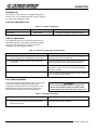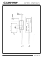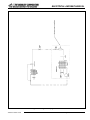
1
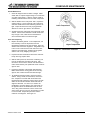
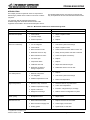
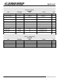
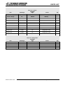
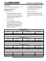
Installation, Operation &
Maintenance Manual
Refrigerated Base – Remote
MODELS
20036RSB
20084RSB
20048RSB
20096RSB
20060RSB
20108RSB
20072RSB
1100 Old Honeycutt Road, Fuquay-Varina, NC 27526
919-552-9161 • 800-348-2558 • 919-552-9798 (fax) • 800-238-8444 (after hours)
Printed in USA 12/02
INTRODUCTION
GENERAL INFORMATION
Safety . . . . . . . . . . . . . . . . . . . . . . . . . . . . . . . . . . . . . . . . .3
This technical manual provides information for the installation,
operation, maintenance, and inspection of this unit
manufactured by Middleby. A complete parts breakdown
is also provided.
Specifications . . . . . . . . . . . . . . . . . . . . . . . . . . . . . . . . . . . .3
Operation . . . . . . . . . . . . . . . . . . . . . . . . . . . . . . . . . . . . . . .4
Functional Description . . . . . . . . . . . . . . . . . . . . . . . . . . . . .5
TECHNICAL SUPPORT
Scheduled Maintenance . . . . . . . . . . . . . . . . . . . . . . . . . . .6
For any questions regarding the installation, operation or
maintenance of the unit, contact the factory at the following
address:
Troubleshooting . . . . . . . . . . . . . . . . . . . . . . . . . . . . . . . . . .9
Corrective Maintenance . . . . . . . . . . . . . . . . . . . . . . . . . . .10
Technical Service Department
Middleby
1100 Honeycutt Road
Fuquay-Varina, NC 27526
Parts List . . . . . . . . . . . . . . . . . . . . . . . . . . . . . . . . . . . . . .13
Installation . . . . . . . . . . . . . . . . . . . . . . . . . . . . . . . . . . . . .20
Electrical and Mechanical . . . . . . . . . . . . . . . . . . . . . . . . .21
SCOPE OF THE MANUAL
Limited Warranty . . . . . . . . . . . . . . . . . . . . . . . . . . . . . . . .24
This manual provides sufficient information for maintenance
of the equipment.
NOTICE! MIDDLEBY RESERVES THE RIGHT
EQUIPMENT DESCRIPTION
TO CHANGE SPECIFICATIONS AND PRODUCT DESIGN
WITHOUT NOTICE. SUCH REVISIONS DO NOT ENTITLE
THE BUYER TO CORRESPONDING CHANGES,
IMPROVEMENTS, ADDITIONS OR REPLACEMENTS
FOR PREVIOUSLY PURCHASED EQUIPMENT.
The unit consists of the following parts:
•
Storage compartment - The insulated food storage
compartment is clear storage area. The cooling coil
(evaporator) is contained in this area.
•
Drawers - Product is stored by means of food pans set in
drawers. The drawer face is made of an insulated panel.
The drawer face (panel) is fully “gasketed”
to provide a tight seal against the cabinet.
•
Condensing Unit Compartment - This area contains
the condensing unit(s) along with the necessary controls
and other components.
•
Evaporator Coil - The evaporator coil is located in the
storage compartment and is responsible for distributing
the cold air associated with the refrigeration system.
•
Cabinet - The cabinet is the enclosure in which all
of the above mentioned items are housed.
EQUIPMENT SUPPLIED
The unit is shipped from the factory assembled. The
complete assembly is palletized and crated to minimize
the possibility of damage in shipping and storage.
Refrigerated Base-Remote © 2002
2
Printed in USA 12/02
SAFETY
SAFETY NOTICES
DANGER
EXPLOSION HAZARD
If gas odor is detected, shut down equipment at the main
shutoff valve. Immediately call the emergency phone
number of your gas supplier.
DANGER
This symbol warns of immediate hazards which WILL
result in severe injury or death.
WARNING
This symbol refers to a potential hazard or unsafe
practice which COULD result in injury or death.
WARNING
FIRE HAZARD
For your safety, do not store or use gasoline or other
flammable vapors and liquids in the vicinity of this or any
other appliance.
CAUTION
This symbol refers to a potential hazard or unsafe
practice which COULD result in injury, product or
property damage.
Keep area around appliances free and clear of
combustibles.
NOTICE! This symbol refers to information that requires
special attention or must be fully understood, even
though not dangerous.
WARNING
Asphyxiation can result from improper ventilation. Do
not obstruct the flow of combustion and ventilation air to
/and from your cooking equipment.
SAFETY PRECAUTIONS
NOTICE! Be sure this manual and important papers are
given to the proper authority to retain for future
reference.
NOTICE! Post the emergency telephone number of your
gas supplier and instructions to follow if gas odor is
detected.
SPECIFICATIONS
Table 1.1 - Leading Particulars
Remote, Refrigerated Bases
Model
Number
20036RSB
20048RSB
20060RSB
20072RSB
20084RSB
20096RSB
20108RSB
W
36"
48"
60"
72"
84"
96"
108"
D
32"
32"
32"
32"
32"
32"
32"
H*
26"
26"
26"
26"
26"
26"
26"
Drawers
18"
26"
31"
2
4
-
2
2
2
2
6
2
2
2
4
No. of
Ref.
Pans
Volume
12"x20"x4" (cu.ft.)
4
4
6
8
8
12
12
6.8
13
14
17.5
21
24.6
28.2
Elec.
V/Ph/Hz
115/1/60
115/1/60
115/1/60
115/1/60
115/1/60
115/1/60
115/1/60
Evap.
BTU
Amps
1100
1100
1100
1600
1600
1600
1600
0.9
0.9
0.9
0.925
0.925
0.925
0.925
Shipping
Weight
(lbs.)
300
400
510
610
715
815
920
*Includes 6" legs or casters
Figure 1.1 - General Arrangement Picture
Printed in USA 12/02
3
Refrigerated Base-Remote © 2002
OPERATION
INTRODUCTION
This model is a heavy-duty piece of equipment designed for
continuous use. It incorporates automatic controls to regulate
the cycling of the refrigeration system.
CONTROLS AND INDICATORS
Table 2.1 - Controls and Indicators
NAME
TYPE
Thermostat
FUNCTION
Contact Points
Cycles the refrigerator system (automatic)
START-UP PROCEDURE
The refrigeration system is to be remotely located from the
refrigerated cabinet. An authorized and certified refrigeration
company should make all of the connections from the
condensing unit to the refrigerated cabinet.
Table 2.2 - Start-up Procedure (Refrigerated Storage)
Operation
Results
1. Activate system by inserting electrical service cord into
electrical supply source and flip power control switch.
Compressor should immediately come on line along with the
condenser fan and the evaporator fan.
2. Locate liquid refrigerant indication glass mounted on
the receiver.
Once the system has been operating for two minutes, the
glass should appear clear and full of liquid refrigerant.
3. Wait 15 minutes.
The temperature in the storage area should begin to
approach the “green zone” on the thermometer indicating
adequate operation.
4. Wait 3 hours.
Once the operating temperature has been reached, stocking
of the containment area can begin.
SHUT-DOWN PROCEDURE
To shut down, disconnect the electrical supply cord and open
or remove the drawer(s) allowing the interior cabinet
temperature to equalize with the room temperature. A mild
detergent diluted in warm water should be used to wash
down the interior and exterior surfaces of the cabinet.
WARNING
Prior to any cleaning of the system involving placing
hands in areas with moving parts, the system should
be deactivated by disconnecting the power supply cord.
Table 2.3 - Shut Down Procedures
Operation
Results
1. De-energize the system by flipping the power control
switch to the “OFF” position and disconnecting the
electrical supply cord.
Refrigerated Base-Remote © 2002
Once the system is de-energized, the condenser fan and the
evaporator fan will cease operation.
4
Printed in USA 12/02
OPERATION
PREPARATION FOR AN EXTENDED PERIOD
OF INACTIVITY
This unit is designed for continued use at automatically
cycled intervals. However, in the event of an extended shut
down, both the mechanical refrigeration system and the food
storage compartment system must be serviced.
Table 2.4 - Shut Down Procedures for an Extended Period
Operation
Results
1. Fully close discharge valve at the receiver.
Compressor will pump liquid refrigerant from system
to receiver.
2. Fully close suction valve at the compressor.
This will isolate the refrigerant between the two valves.
3. Disconnect power supply.
De-energizes the system.
4. Clean and wipe dry the food storage compartment.
This will reduce the odor buildup during shut down.
FUNCTIONAL DESCRIPTION
SYSTEM DESCRIPTION
Special care in the initial loading of the storage compartment
should be taken. It is suggested that the loading be
scheduled in three equal portions allowing three hours
between each loading.
This unit consists of an insulated storage cabinet with
drawers, an evaporator coil, a thermal expansion valve,
a thermostat, and a compartment to make remote
refrigeration and electrical connections. It is designed
with the intent and purpose of storing food items.
The chilled food compartment is designed for the storage
of perishable food items that require a temperature range
of 37 to 40 degrees Fahrenheit. It is a general rule that
adequate spacing is allowed between stored items to allow
for proper air circulation.
SYSTEM OPERATION
The design of the refrigerated cabinet focuses primarily on
the safe storage of food products requiring refrigeration. In
engineering, considerable attention was placed on its
functionality and its serviceability.
Printed in USA 12/02
5
Refrigerated Base-Remote © 2002
SCHEDULED MAINTENANCE
INTRODUCTION
WARNING
The system should be de-energized when checking
for leaks.
To ensure the longest and most trouble free operation of the
unit, a thorough maintenance schedule is required to be
adhered to periodically. The maintenance system should
be designed to maximize the efficient use of maintenance
personnel, reduce down time, and provide the orderly
acquisition of spare parts support.
i. If a leak is found on a flared fitting, it can often be
repaired by simply tightening the brass flare nut 1/4
of a turn. If tightening does not repair the leak, it
may be necessary to reflare the tubing.
The Middleby refrigeration cabinet will generally be in
operation in a facility where scheduled maintenance is
performed according to Maintenance Index Plans. Your unit
is no exception to required maintenance. This section of the
manual is intended as an alternative to any standard
maintenance program that may pre-exist. The preventive
maintenance schedule is based upon similar maintenance
requirements for commercial refrigeration equipment.
ii. If a leak is found on a brazed joint, it will be
necessary to pump down the system’s refrigerant
charge to remedy the problem.
iii. To pump the refrigerant into the receiver, you must
first connect service gauges to the system at the
suction valve on the compressor and the liquid valve
on the receiver. Purge the gauges before opening
the system’s valves to avoid contamination. Run the
receiver (liquid or high pressure) valve all the way in
to stop the refrigerant from exiting the receiver.
Start the unit and allow it to run until the suction or
low-pressure gauge reads 5 lbs. When it reaches
5 lbs., de-energize the system.
PREVENTIVE MAINTENANCE ACTION INDEX
If you do not have a Maintenance Index Plan, one is included
for you in Table 4.1.
PREPARATION FOR MAINTENANCE
iv. Once pumped down, the necessary repairs can be
made.
Since many areas affected by the maintenance schedule are
electrically supplied, it is recommended that the system be
de-energized prior to making the inspections.
4 Using a mild non-abrasive detergent and soft cloth,
wipe the interior lining beginning with the top and
working down. Also, wipe the gasket and where it sits
on the cabinet exterior.
MAINTENANCE
Weekly Inspection
1. The unit should first be de-energized.
5. Check the condenser fan motor and make certain that
it is not loose. Inspect the fan for cracks and make
sure that it is tight on the motori.
2. Using a vacuum or small hand broom, brush the
condenser in a vertical motion to remove any dust or
debris that may have accumulated.
6. To inspect the evaporator motor, first turn the unit off.
Then, remove the drain line from the evaporator pan.
Loosen the four screws that hold the shroud. Lower
the shroud and disconnect the polarized electrical
connection. With the shroud out of the cabinet,
proceed to inspect the motor mounting bolts and the
fan for cracks or excessive play.
Monthly Inspection
1. Check the evaporator drain line at both the inlet
and outlet ends to make certain that there are no
obstructions. It is not recommended to use any
chemicals in clearing a clogged drain. The preferred
method of unstopping an obstructed drain is to use
compressed air. Approximately 60 lbs. should be
sufficient. Simply remove the drain line at the
evaporator coil and attach an air-line to it.
7. Using a mild detergent and water, wipe the vinyl
gasket. Make certain to also clean under the gasket
to remove any mildew or residue.
8. Using a mild, non-abrasive detergent and warm water,
wipe the cabinet exterior. When cleaning always follow
the grain of the stainless steel to prevent scratching
or marring of the finish surface.
2. With the unit in a cooling cycle, use a flashlight and
locate the refrigerant sight glassi. If the compressor
has been running for three minutes there should be no
visible bubbles.
3. If bubbles are present:
a. Determine if there is a leak by using a halide or
electronic leak detector.
b. Repair leak(s).
Refrigerated Base-Remote © 2002
6
Printed in USA 12/02
SCHEDULED MAINTENANCE
Annual Maintenance
1. Check all refrigerant lines for leaks or fatigue. Make
certain that no exposed copper tubing is in contact with
any other metal surface. If there is contact, install an
insulating material between the two metal components.
2. With the breaker at the main panel “OFF”, inspect the
system’s wiring. Look for a tight fit of all connections
and make certain that the wire restraining devices are
tight. Inspect all wires and cords, paying particular
attention to nicks or age cracks in the insulation.
Lower Temperature
3. Visually inspect the outer panel and components of the
cabinet. Check screws and bolts to make certain that
they are tight. Also, make sure that the bolts that
secure the base frame to the deck are tight.
Three Year Frequency
1. Replace the drawer gaskets. To accomplish this, it is
first necessary to remove all products from the
refrigerated compartment to avoid spoilage. Open the
drawers and remove the old gasket. The gaskets snap
in and out of a channel on the back side of the door.
Clean the track thoroughly. Replace the old gasket
with the new one by snapping it into place.
Higher Temperature
Figure 4.1 - Thermometer Calibration
2. Inspect all motors and shaftsi for both noise and wear.
If they show age, replace them.
3. With the main power off, remove the condensing unit
from its compartment and inspect all wiring. Also,
remove the cover from the controls and check them to
make certain that they are operational and do not show
signs of wear.
4. Inspect the operation of the drawer slide assembly.
Make certain that the moving parts do not show any
signs of wear. Make sure that all screws are tight.
5. To recalibrate the thermometer, remove it from the
cabinet. Using a small, flat screwdriver, remove the
lens. Prepare an ice water bath and immerse the
thermometer bulb at least two inches into the ice bath.
WIthin 30 seconds the indicator dial should read 32
degrees Fahrenheit. If it does not, it needs to be
recalibrated. Do this by placing your index finger on
the opposite side of the needle that needs to move.
Then, using a flat screwdriver, turn the screw at the
center of the dial 1/4 of a turn in the direction you want
to move the dial. Repeat the procedure until the
needle is on 32 degrees. See Figure 4.1.
Printed in USA 12/02
7
Refrigerated Base-Remote © 2002
SCHEDULED MAINTENANCE
Table 4.1 - Preventative Maintenance Action Index
1.
Weekly
a. Inspect condenser coili to make certain that air flow is not
hampered and that it is clear of dust and debris.
2.
Monthly
a. Inspect and clear drain line.
b. Check the liquid refrigerant sight glassi to make certain that
the system is completely charged.
c. Clean the interior of the cabinet with a mild soap and warm
water solution. Be certain to dry thoroughly.
d. Check both the condenser fan motori and the evaporator
fan motor to make certain that they are operational and that
the fans are tight and secure.
e. Clean door gaskets and breaker strips with a damp cloth.
f. Clean exterior of cabinet with mild soap and warm water.
Dry thoroughly.
3.
Annually
a. Check all joints and fittings for any signs of leaks or fatigue.
b. Inspect electrical connections to confirm that there is good
contact and that wires are neither weakened nor frayed.
c. Check the integrity of the cabinet.
4.
Three-year Frequency
a. Replace door gaskets.
b. Inspect motor shaftsi for noise or wear.
c. Inspect electrical controls and wiring.
d. Inspect drawer slides.
e. Recalibrate thermometer.
i
If supplied with a condensing unit
Refrigerated Base-Remote © 2002
8
Printed in USA 12/02
TROUBLESHOOTING
INTRODUCTION
This chapter provides a systematic check of components in
determining a possible cause of failure in the event of various
symptoms.
The following tables list the most common symptoms that
may be experienced and the recommended corrective action.
It is necessary that the individual performing the
troubleshooting tasks be familiar with the function of the
equipment as described in the Functional Description section.
Table 5.1 - Mechanical and Electrical Troubleshooting Guide
SYMPTOM
REMEDY
1. Control failure
1. Adjust or replace control
2. Incorrect voltage
2. Correct
3. Failed compressori
3. Replace
1. Low on refrigerant
1. Leak check system and recharge
2. Control failure
2. Adjust or replace control
3. Bad connection at TXV
3. Check and secure sensor bulb to suction line
4. Restricted air flow or dirty
4. Rectify air flow problem and clean condenser
5. Bad condenser fan motori
5. Check and replace if necessary
6. TXV stuck open
6. Replace
7. Compressor failure
7. Replace
8. Ineffective door seal
8. Adjust door strike and hinges
9. Restricted circulation in
storage compartment
9. Redistribute food for even air flow
1. Defective compressori
1. Replace
2. Low refrigerant
2. Leak check system and recharge
3. Ambient temperature too low
3. Raise room temperature
1. Blocked or dirty condenseri
1. Clean and remove any obstructions
2. Ambient temperature too high
2. Lower room temperatures
3. System contains air
3. Evacuate, change filter dryer, recharge
4. Refrigerant overcharge
4. Reduce amount of refrigeration in system
Short cycling
1. Maladjusted control
1. Adjust control
Unit does not cool
1. Blown fuse/circuit breaker
1. Replace fuse/reset circuit breaker
2. Bad connection at supply cord
2. Check supply cord at outlet
3. Ill fitting gasket
3. Tighten strike on door latch
Unit does not operate
Unit runs continuously
Low head pressure
High head pressure
i
POSSIBLE FAILURE
If supplied with a condensing unit
Printed in USA 12/02
9
Refrigerated Base-Remote © 2002
CORRECTIVE MAINTENANCE
INTRODUCTION
7. The final step in removing the compressor is to
disconnect it from its mounting. To free the
compressor, remove the wire clips on each of the four
feet.
This chapter focuses on the instruction needed in the
removal and replacement of certain components. It also
addresses the repair of components not listed under the
scheduled maintenance index covered in the Scheduled
Maintenance section.
8. To install the compressor, place it in position on the
base and reinstall the four wire clips.
The level of skills required to perform the service or repair will
vary. Some may require specific training while others may be
performed by any type of mechanic. It is up to the individual
and his/her supervisor to determine the breadth of knowledge
required to perform the necessary service or to make the
necessary repairs.
9. Reattach the suction and discharge valve blocks to the
appropriate sides of the compressor.
10. Reattach the low-pressure control capillary tube and
service fittings to the suction side of the compressor.
11. Reattach the suction line to the compressor.
It is also important to know that any procedure requiring the
handling of refrigerant requires proper certification.
12. In reconnecting the high-pressure line, it is necessary
to first prepare the line’s end. Using a fine sandpaper
or emery cloth, clean the residue off of the end. Also,
clean the connection on the compressor. Apply flux to
both ends and braze the connections into place.
The service or repair items are limited to those parts listed in
Table 7-3.
REPAIR PROCEDURES
13. Remove the valve stem cap from the suction valve
block on the side of the compressor. Run the valve
stem all of the way out and then in one turn clockwise.
WARNING
Prior to performing any work on the refrigeration system,
it is required that the unit be de-energized.
Replacement of Compressor Motor
14. Place the refrigeration service manifold gauge hoses
on the suction and high-side valves. Attach a bottle of
refrigerant to the charging hose and charge the system
with 150 psi of vapor. Using an electronic leak
detector, check the new connections for leaks. Should
a leak appear, evacuate the charge and repair the leak.
Repeat the leak check process again.
i
1. Evacuate the refrigerant from the system using a
refrigeration vacuum pump.
NOTE: Federal laws require the proper handling and
disposal of refrigerant. It is unlawful to release any
refrigerant into the atmosphere.
15. If the system checks out with no leaks, recover the test
charge using a vacuum recovery pump.
2. Disconnect the electrical power to the unit. This is
done by turning off the circuit in the main supply panel.
It should be noted on the panel that the refrigerator is
being serviced and that the breaker must remain off.
16. With the system pressure at zero, connect the vacuum
pump and evacuate the system. The pump should run
for one hour. The vacuum pump should pull the
system down to 30 inches of vacuum.
3. Find the electrical terminal box on the side of the
compressor and remove the front cover. Disconnect
the wires from the compressor. Remove the screws
that attach the terminal box to the compressor. At this
point, the compressor will be electrically detached.
17. Reattach the electrical terminal box and secure all
wiring.
18. Check the refrigeration tag on the unit for the number
of ounces of refrigerant to place into the system for
start-up. Monitor the pressure on both the suction and
discharge sides of the manifold gauges. As the
temperature in the storage area begins to fall, check
the refrigerant flow through the sight glass. The unit is
fully charged when there are no bubbles in the sight
glass. If after five minutes of operation, bubbles are
still present, it may be necessary to add more
refrigerant (add refrigerant in small amount to keep
from overcharging).
4. Using wrenches, remove the suction and discharge
valve stem cover caps on each side of the compressor.
Also, remove the cap nut on the suction and discharge
side as well.
5. Disconnect the high-side line at the compressor. This
is done by heating the brazed connection using an
acetylene and oxygen torch set.
NOTE: Do not apply a flame to a line containing refrigerant.
WARNING
Overcharging a refrigeration system can be dangerous.
6. To remove the low-pressure control capillary tube and
service fitting, loosen the 1/4" brass flare nut on the
suction valve.
Refrigerated Base-Remote © 2002
10
Printed in USA 12/02
CORRECTIVE MAINTENANCE
If the system overcharge is sufficient enough to immerse the
major parts of a hermetic compressor in liquid refrigerant, a
situation has been created that when followed by unusual but
possible circumstances, can lead to compressor housing
seam separation or rupture.
6. Using a standard screwdriver, coarse adjust the control
by turning the adjustment screws on top of the control.
Preset the cut-in and cutout and 68 lbs. and 38 lbs.
respectively for a refrigerator and 25 lbs. and 10 lbs.
respectively for a freezer.
The sequence of circumstances that can lead to compressor
housing seam separation or rupture occurs in the following
manner:
7. Start the system. Allow it to run for five minutes.
Monitor the low side pressure. Fine adjustments will
be required to achieve the prescribed cycling
pressures.
1. The system overcharge immerses the compressor
motor, piston, connecting rods, cylinders, etc. in liquid
refrigerant, thereby effectively forming a hydraulic block
preventing the compressor from starting. This
condition is known as locked rotor.
NOTE: Running the suction valve in or out as required to
effectively change the pressures can speed up the control
adjustment process.
Replacement of Thermal Expansion Valve (TXV)
2. Electrical current continues to flow through the
compressor motor windings that become, in effect,
electric resistance heaters. The heat produced begins
to vaporize the excessive liquid overcharge, causing a
rapid increase in system pressure.
1. Close liquid valve and run compressor until it pumps
refrigerant into the receiver (low side service gauge will
read 1 lbs.). Close the suction line valve.
2. Disconnect the sensor bulb on the suction line.
3. If the system compressor protective devices fail for any
reason prior to or during this locked rotor heating cycle
or cycles, liquid refrigerant may be vaporized
sufficiently fast enough to raise the pressure within the
system to extremes far greater that the housing or weld
seam is designed to handle.
3. Disconnect the liquid line (1/4") and suction line (3/8")
then remove the TXV.
4. Install new TXV, reconnect lines, and re-fasten the
sensor bulb.
NOTE: It is not recommended to adjust the valve super heat
as this comes pre-set from the factory.
4. In some instances where the amount of refrigerant
overcharge is critical in proportion to the system
internal volume, the pressure reached can cause a
compressor housing seam separation or rupture that
can be hazardous.
Replacement of Filter Dryeri
1. Close liquid line valve and run compressor until the low
side refrigeration gauge indicates zero lbs., then close
suction.
The remedy to eliminate this exceedingly rare, but potential
hazard is to use correct refrigerant charge amounts and
techniques.
2. Remove filter dryer from system and replace with new
dryer.
Middleby urges that all individuals responsible for training,
teaching, or advising installation mechanics and service
personnel emphasize proper charging techniques. In
addition, Middleby advises strict adherence to refrigerant
charge amounts specifically recommended by the
manufacturer of the refrigeration, air conditioning, or heat
pump system.
3. Purge system and add refrigerant if needed.
Replacement of Condenser Fan Motori
1. Disconnect all electrical power to the unit.
2. Remove the condensing unit from the condensing unit
compartment.
Replacement of Low Pressure Control
3. Remove the protective wire shroud from around the
motor.
1. Disconnect the unit from electrical service.
2. Remove control cover and disconnect electrical
terminals.
4. Disconnect the fan motor leads from the terminal box
on the compressor.
3. Disconnect capillary tube.
5. Remove the mounting screws at the motor base.
4. Remove mounting fasteners on control base and install
new control by reversing the procedure.
6. Using an allen wrench, remove the aluminum fan.
7. To install the new motor, reverse the process.
5. To adjust the control, hook up the service gauges to
the suction and discharge valves and crack them to
allow the gauges to read.
Printed in USA 12/02
11
Refrigerated Base-Remote © 2002
CORRECTIVE MAINTENANCE
Replacement of the Drain Line
Replacement of the Condensing Fani
NOTE: To replace the vinyl drain line, it is necessary that
there be access to the rear of the cabinet.
1. Disconnect all electrical power to the unit.
2. Remove the condensing unit from the condensing unit
compartment.
1. On the cabinet exterior, remove the rear tubing cover
using a 1/4" nut driver.
3. Remove the protective wire shroud from around the
motor.
2. On the interior of the cabinet, remove the drain line
cover.
4. Using an allen wrench, loosen the set screw on the
blade hub and slide the blade from the shaft.
3. From the inside of the cabinet, pull the drain from the
evaporator shroud fitting.
5. Reverse the procedure to reassemble.
4. From the drain exit location, pull the drain through the
penetration of the cabinet.
Replacement of the Anti-Condensate Heater
NOTE: The anti-condensate heater is located behind the
front edge of the vinyl breakers in the door opening.
5. At the bottom of the condensing unit compartment, cut
the drain line retaining strap. The drain line should
now be free.
1. Disconnect all electrical power to the cabinet.
6. To install the new drain line, reverse the process.
2. Remove vinyl breakers by exerting pressure at the
front edge toward the center of the door.
CHARGING THE REFRIGERATION SYSTEMi
3. Disconnect anti-condensate heater wiring connection.
1. Connect service gauges to the suction and discharge
service valves then open valves one full turn.
4. Remove heater from recessed rail.
2. If the system is pressurized slightly, open both manifold
gauge valves and purge the service line gauges.
5. Replace new heater in rail and reconnect electrical.
Replacement of Drawer Gasket
3. With manifold gauge valves closed, start refrigeration
system.
1. Remove the gasket by pulling it out of the snap-in
track.
4. Attach a drum of refrigerant to the suction service side
of the manifold gauges and add refrigerant until the
liquid sight glass is clear of bubbles.
2. Clean the gasket track and the immediate area.
3. Snap new gasket into retainer.
RECALIBRATING THE THERMOMETER
Replacement of Power Switch
1. To recalibrate the thermometer, remove it from the
cabinet. Using a small, flat screwdriver, remove the
lens. Prepare an ice water bath and immerse the
thermometer bulb at least two inches into the ice bath.
Within 30 seconds the indicator dial should read 32
degrees Fahrenheit. If it does not, it needs to be
recalibrated. Do this by placing your index finger on
the opposite side of the needle that needs to move.
Then, using a flat screwdriver, turn the screw at the
center of the dial 1/4 of a turn in the direction you want
to move the dial. Repeat the procedure until the
needle is on 32 degrees. See Figure 4.1.
1. Shut off all electrical power going to the unit.
2. Remove the front air grill.
3. Using a flat blade screwdriver, remove the cover plate
with the switch attached.
4. Remove the wires connected to the switch.
5. Unscrew the lock washer and remove the switch.
6. Reverse the process when installing the new switch.
i
Refrigerated Base-Remote © 2002
12
If supplied with a condensing unit
Printed in USA 12/02
PARTS LIST
INTRODUCTION
This section of the manual contains lists of replaceable parts.
Each of the tables contains a list of removable parts
associated with an assembly of the cabinet or refrigeration
system. No parts identification has been provided for details
of permanently assembled items or those that are not
suitable for field repair.
Table 7.1 is a parts list of special tools required for routine
service.
Table 7.1 - Parts List - Special Tools List
Part Number
Description
Quantity
R1412
Refrigerant service gauges with hoses
1
VA70264
Service valve wrench
1
50992
Refrigerant
30 lbs.
Table 7.2 - Parts List
Middleby#
Parts List - Cabinet
20036RSB
Mfg#
Vendor
Qty
26"
DSB26C
Middleby
1
GSB60MV
6449
Jeans
2
Recessed Pulls
HXHL08
P73-2000
Component Hardware
2
Drawer Rollers
HXDW02
7319000201
Kason
8
Heater Wire
L1HR82
82"
Refrigeration Hdwe.
1
CNNP01MS
3/4" large hex nut
Best Bolt
4
Middleby#
Parts List - Refrigeration
20036RSB
Mfg#
Vendor
Qty
RWE430
RWEM03
RWE5101B
RWEV39
RWTT08
BBM11A
25300701
5101B
EFS1/4C
A319ABC-24-01
Heatcraft
Heatcraft
Heatcraft
Sporlan
Johnson Controls
1
1
1
1
1
Item
Drawer Cartridge
Gasket
Leg nut
Item
Evaporator Coil Assy.
Evaporator Motor
Evaporator Fan
Expansion Valve
Thermostat
Printed in USA 12/02
13
Refrigerated Base-Remote © 2002
PARTS LIST
Middleby#
Parts List - Cabinet
20048RSB
Mfg#
Vendor
Qty
31"
DSB31C
Middleby
1
GSB64MV
6449
Jeans
2
Recessed Pulls
HXHL08
P73-2000
Component Hardware
2
Drawer Rollers
HXDW02
7319000201
Kason
8
Heater Wire
L1HR90
90"
Refrigeration Hdwe.
1
CNNP01MS
3/4" large hex nut
Best Bolt
4
Middleby#
Parts List - Refrigeration
20048RSB
Mfg#
Vendor
Qty
RWE430
RWEM03
RWE5101B
RWEV39
RWTT08
BBM11A
25300701
5101B
EFS1/4C
A319ABC-24-01
Heatcraft
Heatcraft
Heatcraft
Sporlan
Johnson Controls
1
1
1
1
1
Item
Drawer Cartridge
Gasket
Leg nut
Item
Evaporator Coil Assy.
Evaporator Motor
Evaporator Fan
Expansion Valve
Thermostat
Refrigerated Base-Remote © 2002
14
Printed in USA 12/02
PARTS LIST
Item
Middleby#
Parts List - Cabinet
20060RSB
Mfg#
Drawer Cartridge
18"
DSB18C
Middleby
1
Drawer Cartridge
26"
DSB26C
Middleby
1
Gasket
GSB60MV
6449
Jeans
1
Gasket
GSB62MV
6449
Jeans
1
Recessed Pulls
HXHL08
P73-2000
Component Hardware
2
Drawer Rollers
HXDW02
7319000201
Kason
8
Heater Wire
L1HR64
64"
Refrigeration Hdwe.
1
Heater Wire
L1HR82
82"
Refrigeration Hdwe.
1
CNNP01MS
3/4" large hex nut
Best Bolt
4
Middleby#
Parts List - Refrigeration
20060RSB
Mfg#
RWE430
RWEM03
RWE5101B
RWEV39
RWTT08
BBM11A
25300701
5101B
EFS1/4C
A319ABC-24-01
Leg nut
Item
Evaporator Coil Assy.
Evaporator Motor
Evaporator Fan
Expansion Valve
Thermostat
Printed in USA 12/02
15
Vendor
Vendor
Heatcraft
Heatcraft
Heatcraft
Sporlan
Johnson Controls
Qty
Qty
1
1
1
1
1
Refrigerated Base-Remote © 2002
PARTS LIST
Item
Middleby#
Parts List - Cabinet
20072RSB
Mfg#
Drawer Cartridge
26"
DSB26C
Middleby
1
Drawer Cartridge
31"
DSB31C
Middleby
1
Gasket
GSB62MV
6449
Jeans
2
Gasket
GSB64MV
6449
Jeans
2
Recessed Pulls
HXHL08
P73-2000
Component Hardware
4
Drawer Rollers
HXDW02
7319000201
Kason
16
Heater Wire
L1HR64
64"
Refrigeration Hdwe.
1
Heater Wire
L1HR90
90"
Refrigeration Hdwe.
1
CNNP01MS
3/4" large hex nut
Best Bolt
4
Middleby#
Parts List - Refrigeration
20072RSB
Mfg#
RWE430
RWEM03
RWE5101B
RWEV39
RWTT08
BBM11A
25300701
5101B
EFS1/4C
A319ABC-24-01
Leg nut
Item
Evaporator Coil Assy.
Evaporator Motor
Evaporator Fan
Expansion Valve
Thermostat
Refrigerated Base-Remote © 2002
16
Vendor
Qty
Vendor
Qty
Heatcraft
Heatcraft
Heatcraft
Sporlan
Johnson Controls
1
1
1
1
1
Printed in USA 12/02
PARTS LIST
Item
Middleby#
Parts List - Cabinet
20084RSB
Mfg#
Drawer Cartridge
18"
DSB18C
Middleby
2
Drawer Cartridge
26"
DSB26C
Middleby
1
Gasket
GSB60MV
6449
Jeans
4
Gasket
GSB62MV
6449
Jeans
2
Recessed Pulls
HXHL08
P73-2000
Component Hardware
4
Drawer Rollers
HXDW02
7319000201
Kason
16
Heater Wire
L1HR64
64"
Refrigeration Hdwe.
2
Heater Wire
L1HR82
82"
Refrigeration Hdwe.
1
CNNP01MS
3/4" large hex nut
Best Bolt
6
Middleby#
Parts List - Refrigeration
20084RSB
Mfg#
RWE430
RWEM03
RWE5101B
RWEV39
RWTT08
BBM11A
25300701
5101B
EFS1/4C
A319ABC-24-01
Leg nut
Item
Evaporator Coil Assy.
Evaporator Motor
Evaporator Fan
Expansion Valve
Thermostat
Printed in USA 12/02
17
Vendor
Vendor
Heatcraft
Heatcraft
Heatcraft
Sporlan
Johnson Controls
Qty
Qty
1
1
1
1
1
Refrigerated Base-Remote © 2002
PARTS LIST
Item
Middleby#
Parts List - Cabinet
20096RSB
Mfg#
Drawer Cartridge
26"
DSB26C
Middleby
3
GSB62MV
6449
Jeans
2
Recessed Pulls
HXHL08
P73-2000
Component Hardware
6
Drawer Rollers
HXDW02
7319000201
Kason
24
Heater Wire
L1HR82
82"
Refrigeration Hdwe.
3
CNNP01MS
3/4" large hex nut
Best Bolt
6
Middleby#
Parts List - Refrigeration
20096RSB
Mfg#
RWE430
RWEM03
RWE5101B
RWEV39
RWTT08
BBM11A
25300701
5101B
EFS1/4C
A319ABC-24-01
Gasket
Leg nut
Item
Evaporator Coil Assy.
Evaporator Motor
Evaporator Fan
Expansion Valve
Thermostat
Refrigerated Base-Remote © 2002
18
Vendor
Qty
Vendor
Qty
Heatcraft
Heatcraft
Heatcraft
Sporlan
Johnson Controls
1
1
1
1
1
Printed in USA 12/02
PARTS LIST
Item
Middleby#
Parts List - Cabinet
20108RSB
Mfg#
Drawer Cartridge
26"
DSB26C
Middleby
3
Drawer Cartridge
31"
DSB31C
Middleby
2
Gasket
GSB62MV
6449
Jeans
2
Gasket
GSB64MV
6449
Jeans
4
Recessed Pulls
HXHL08
P73-2000
Component Hardware
6
Drawer Rollers
HXDW02
7319000201
Kason
24
Heater Wire
L1HR64
64"
Refrigeration Hdwe.
1
Heater Wire
L1HR90
90"
Refrigeration Hdwe.
2
CNNP01MS
3/4" large hex nut
Best Bolt
6
Middleby#
Parts List - Refrigeration
20108RSB
Mfg#
RWE430
RWEM03
RWE5101B
RWEV39
RWTT08
BBM11A
25300701
5101B
EFS1/4C
A319ABC-24-01
Leg nut
Item
Evaporator Coil Assy.
Evaporator Motor
Evaporator Fan
Expansion Valve
Thermostat
Printed in USA 12/02
19
Vendor
Vendor
Heatcraft
Heatcraft
Heatcraft
Sporlan
Johnson Controls
Qty
Qty
1
1
1
1
1
Refrigerated Base-Remote © 2002
INSTALLATION
UNPACKING
CAUTION
Low or excessive voltage can severely damage the
electrical system.
Note: Before unpacking the unit, note any crate markings
and check for damage to crating. Notify the carrier if there
should appear to be damage to the unit.
Note: Adjusting any valves or controls on the system is not
necessary and may void your warranty. All valves and
controls have been set by the factory.
The unit is shipped directly from the manufacturing factory
securely fastened to a single pallet then protected by an
external wrapping.
i
When a condensing unit is supplied
1. After inspection, carefully remove all external
wrappings and other protective coverings.
2. Review the installation section of the manual
completely prior to installing the unit.
3. Discard crating materials.
INSTALLATION
1. Before moving the unit to the installation sight, doublecheck passageways to ensure that the unit will move
through without modification.
Note: In certain instances, it may be necessary to remove
the drawers. This will allow the unit to fit through tighter
spaces.
2. Position the unit to allow for sufficient ventilation.
Typically, approximately 3" clearance from walls and
other equipment is sufficient.
3. Level the cabinet from front to back and side to side.
This is important so that the cabinet will not be pulled
out of square.
4. Evaporator coil drain lines are factory installed and are
either plumbed into a condensate evaporator pan or
the condensate evaporative base of the condensing
uniti to eliminate the need for exterior plumbing. Make
certain that the drain outlet is located such that the
condensate falls into the pan or base. On units with
remotely located refrigeration, the condensate
evaporator pan is optional.
5. Check the door gasket to make certain that it is sealing
properly to the cabinet.
6. Before applying electrical power to the unit, you should
first check the electrical characteristics of the
condensing unit to ensure that they agree with those of
the electrical supply source.
Refrigerated Base-Remote © 2002
20
Printed in USA 12/02
ELECTRICAL AND MECHANICAL
INTRODUCTION
It may be well to note that the practice in the past
was to show an additional column marked, "LRA
U.L. Test Report". This is no longer needed since
the U.L. investigation work, regarding component
rating, will be guided by the compressor
manufacturer's published value.
This section of the manual contains drawings and schematics
of the electrical and mechanical piping systems.
ELECTRICAL ABBREVIATIONS
AND TERMINOLOGY
•
•
RLA - Rated Load Amperage
Maximum continuous current is a limiting ampere
value that must not be greater than 156% of the
RLA of the compressor as marked on the nameplate
of the particular unit into which that compressor is
applied.
Rated load amps is a measure of the current drawn
by a compressor when operated at compressor
manufacturer rating conditions at nominal voltage.
This value is listed at U.L. and C.S.A. as "RLA". It is
in agreement with the N.E.C. definition that the RLA
be the current draw when the compressor is
delivering rated output.
•
MCG - Maximum Continuous Current
LRA - Locked Rotor Amperage
The locked rotor amps of a compressor is the
current value recorded three seconds after rated
voltage is applied under locked rotor conditions from
a 75 degree Fahrenheit motor soakout temperature
(The voltage drop is to be predetermined and
adjusted accordingly prior to testing). This value
appears on the compressor serial plate and on all
compressor statistics sheets.
Table 9.1 - Operating Pressures
REFRIGERANT: R-12
Cabinet
Ambient
Suction Pressure
Head Pressure
-5 degrees F (Fre.)
37 degrees F (Ref.)
90 degrees F
90 degrees F
0-10 lbs.
18-35 lbs.
120-150 lbs.
120-150 lbs.
REFRIGERANT: R-22
Cabinet
Ambient
Suction Pressure
Head Pressure
-5 degrees F (Fre.)
37 degrees F (Ref.)
90 degrees F
90 degrees F
10-15 lbs.
37-67 lbs.
200-250 lbs.
200-250 lbs.
REFRIGERANT: 134A
Cabinet
Ambient
Suction Pressure
Head Pressure
-5 degrees F (Fre.)
37 degrees F (Ref.)
90 degrees F
90 degrees F
-5-10 lbs.
16-37 lbs.
120-150 lbs.
120-150 lbs.
REFRIGERANT: 404A
Cabinet
Ambient
Suction Pressure
Head Pressure
-5 degrees F (Fre.)
37 degrees F (Ref.)
90 degrees F
90 degrees F
15-20 lbs.
68-84 lbs.
250-300 lbs.
250-300 lbs.
Printed in USA 12/02
21
Refrigerated Base-Remote © 2002
ELECTRICAL AND MECHANICAL
Figure 9.1 - Electrical Schematic
Refrigerated Base-Remote © 2002
22
Printed in USA 12/02
ELECTRICAL AND MECHANICAL
Figure 9.2 - Refrigeration Piping Schematic
Printed in USA 12/02
23
Refrigerated Base-Remote © 2002
LIMITED WARRANTY
INTRODUCTION
To Secure Warranty Service
1. To claim a defect under this warranty, direct your claim
to whomever you purchased the product. Be prepared
to provide the model number, serial number, and a
description of the problem.
Middleby warrants their cabinets and units to consumers only
against defects in material or workmanship under normal use
and service for a period of one year from the date of
shipment. Middleby will repair or replace at their option, any
part, assembly, or portion thereof, which, by their
examination, is deemed to be defective. Middleby will pay
the labor costs for the repair up to twelve (12) months from
the date of shipment.
2. If the above procedure fails to satisfy your claim, you
may write directly to the Middleby, 1100 Old
Honeycutt Road, Fuquay-Varina, NC 27526. Again,
please provide the model number, serial number,
and a description of the problem.
TERMS
Note: There is no other express warranty on Middleby units
except as stated herein. Any implied warrants of fitness and
merchantability are limited in duration to the duration of this
warranty. The liabilities of Middleby are limited solely and
exclusively to replacement as stated herein and do not
include any liability for any incidental, consequential, or other
damages of any kind whatsoever, whether any claim is based
upon theories of contract negligence or tort. Some states do
not allow limitations on how long an implied warranty lasts, or
the exclusion of limitations of incidental or consequential
damages. So, the above limitations and exclusions may not
apply to you. This warranty gives you specific legal rights
and you may also have other rights that vary from state
to state.
Exclusions
•
Middleby’s obligations under this warranty shall not
extend to any malfunction or other problem caused by
unreasonable use, such as, but not limited to, improper
setting of controls, improper installation, improper voltage
supply, loose electrical connections or blown fuses, and
damage not attributable to a defect in workmanship.
This warranty will not apply to any cabinet or component
part that has been subject to any accident, abuse,
misuse, damage caused by fire or floor or any other act
of God, and to any product serviced by an unauthorized
service person or company.
•
Middleby will not accept responsibility for the labor costs
related to service and repair of remote condensing units
or other field installations.
•
It remains the responsibility of the qualified refrigeration
installation company to provide any accessories required
for a specific climate or application. Middleby does not
imply nor warrant the use of this equipment in adverse
conditions or beyond its intended use.
Refrigerated Base-Remote © 2002
24
Printed in USA 12/02