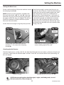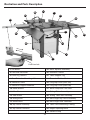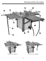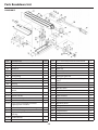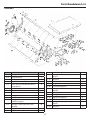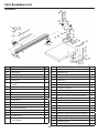
1
Code 501196 ( AW10BSB2) Code 501197 (AW12BSB2) AW10BSB2,AW12BSB2 Sliding Table Kit Saw Bench Code: 951539 AW10BSB2 AW12BSB2 Table Extension Set Setup 1 Setup 2 Code: 951538 AW10BSB2 Code: 951541 AW12BSB2 Saw Bench Package Code: 718652 AW10BSB2 Code: 718653 AW12BSB2 AT&M: 08/12/2014 REF: 508304 Index of Contents Page Index of Contents 02 Declaration of Conformity 03 Parts Index 04-05-06 General Instructions for 230V Machines 06-07 Specification08 Initial Assembly Saw Body Assembly Fitting Hand Wheels Fitting Kick Plate Saw Guard Assembly Mitre Fence Assembly Rip Fence Assembly Micro-Adjuster Assembly Rip Fence Extension 09-10-11 11-12 12 12-13-14 16 14-15 15 16 951538 10” and 951541 12” Table Extension Kits (Box 1 of 2) and (Box 2 of 2) Setup 1 Setup 2 17-18 18-19 951539 10” and 12” Sliding Table Kits (Box 1 of 2) and (Box 2 of 2) Mounting Bracket/Adjuster Block Assembly Slide Rail and Table Assembly Mitre Angle Rip Fence Assembly 20-21 21-22 22-23 Setting the Machine Setting the Table Setting the Sliding Tables Setting the Angle Fence to the Saw Blade Setting the Rip Fence Setting the Mitre Fence Checking the Belt Tension Specific Instructions/Precautions for the Saw Bench Operating Instructions Illustration and Parts Description Changing the Saw Blade 24 24-25-26 27-28 28 29 29-30 30-31 31 32-33-34 35-36 Maintenance36 Wiring Diagram 37 Parts Breakdown/List Diagram A (Saw Bench Assembly) 38-39 Diagram B ( Saw Bench Table and Extension Tables Assembly) 40-41-42 Diagram C (Mitre Fence Assembly) 43 Diagram C (Mitre Fence Assembly) 43-44 Diagram D (Saw Mechanism Assembly) 44-45 Diagram E (Rip Fence Assembly) 46 Diagram F (Sliding Table Assembly) 47 Diagram G (Mitre Angle Rip Fence Assembly) 48 Notes49-50-51 02 Declaration of Conformity Copied from CE Certificate manufactured by Laizhou Fulin Machinery Co. is in compliance with the following standards or standardisation documents inaccordance with Council Directives The undersigned, F. Nispel authorised by Laizhou Fulin Machinery Co., Ltd.No. 275 Wenquan East Road Laizhou, Shandong 261400 P.R. China declares that this product: EN 61000-3-3: 1995+A1 EN 55014-2: 1997+A1 EN 61000-3-2: 2000 EN 55014-1: 2000+A1 Model number MJ2325D/MJ2330D Table Saw WARNING! Under no circumstances should CHILDREN be allowed in work areas IT IS RECOMMENDED THAT YOU WEAR EAR PROTECTION WHEN USING THIS MACHINE Warning! Fully read manual and safety instructions before use The symbols below advise that you follow the correct safety procedures when using this machine. Eye protection should be worn Ear protection should be worn Foot protection should be worn Two man assembly 03 Dust mask should be worn Keep hands away from moving parts and cutting area Parts Index Model Number: MJ2325D/MJ2330D 501196 10” and 501197 12” Saw Bench (Box 1 of 2) 1 off: Saw Table on upper chassis (with motor, table insert, saw blade & NVR Switch fitted) 1 2 off: Side Panels and Front & Back Panels 2 4 off: Lower Leg Columns 3 1 off: Side Table Extension 3A 4 1 off: Dust Extraction Moulding 100mm 4A 1 off: Dust Extraction Hose 100mm Bag Containing: 4B 8 off: M8 x 25mm Square bolts, washer and nuts(for 501196,8pcs;for 501197,7pcs) 4 off: M8 x 20mm Bolts, washers (for the connection of worktable & extension table) 4 off: M6 x 16mm Phillips screws, washers/nuts 4 off: M8 x 16mm Bolts, washers and nuts 5A 16 off: M8 x 16mm Bolts, washers and nuts 5B 5 1 off Rear Extention Table 6 2 off: Extention Table Support Brackets 7 2 off: Clamping Plates with pre-drilled holes 8 Bag Containing: 4 off: M8 x 20mm Caphead Bolts 4 off: M8 x 20mm Caphead Bolts and washers 9 2 off Hand Wheels and locating keys 10 1 off: Mitre Fence and Mitre Fence Extension with clamping screw knobs 11 1 off: Mitre Fence Steel Plate with pre-driled holes 12 1 off: Saw Guard with Phillips screw/nut and coach bolt/knob 13 1 off: Riving knife 14 1 off: M6 x 40mm Coach bolt and knob 15 2 off: 125mm and 50mm Hose Clips 16 1 off: 30mm hose 17 1 off: Tommy Bar 18 1 off: Spanner for (Changing the Blade) 18A 1 off: Push stick 18B 2 off: 13/17mm Spanners 19 Hex Keys: 3,4,5,6 and 8mm 19A Bag Containing: Bag Containing: 1 off: Instruction Manual 04 Parts Index 501196 10” and 501197 12” Saw Bench (Box 2 of 2) 1 off: Rip Fence Assembly (partially assembled) 20 1 off: Rip Fence Extension 21 1 off: Short Rip Fence (front rail) 22 1 off: Short Rip Fence (back rail) 23 Bag Containing: 24 2 off: ‘T’ bolts M6 x 70mm and M6 knobs 2 off: Plastic Capping Plates (for ends of the rip fence mounting bracket) 24A 2 off: Plastic Capping Plates (for ends of front rip fence rail) 24B 8 off: 4mm Round head self tapping screws 24C 25 1 off: Micro Adjuster Assembly 951538 10” and 951541 12” Table Extension Kits (Box 1 of 2) 2 off: Extension Tables with M8 x 25mm ‘T’ bolts, washers and nuts 26 1 off: Table support leg 27 1 off: Threaded rubber foot 28 Bag Containing: 29 8 off: M8 x 30mm bolts, washers and nuts 30 2 off M8 x 20mm bolts washers and nuts 31 951538 10” and 951541 12” Table Extension Kits (Box 2 of 2) 1 off: Long Rip Fence (front rail) 32 1 off: Long Rip Fence (back rail) 33 1 off: Measuring scale extension label 34 951539 10” and 12” Sliding Table Kits ( Box 1 of 2) 2 off: Sliding Table Mounting Brackets 35 2 off: Steel Clamping Plates (for Mounting brackets) 36 1 off Work Clamp and Tool Post 37 1 off: Sliding Table Assembly 38 Bag Containing: 6 off: M10 x 19mm Hex bolts (for table adjustment) 39 951539 10” and 12” Sliding Table kits ( Box 2 of 2) 1 off: Sliding Table Rail Assembly 40 1 off: Mitre Angle Rip Fence Assembly 41 05 Continues Over.... Parts index 951539 10” and 12” Sliding Table kits ( Box 2 of 2) Mitre Angle Rear Quadrant (with lift and shift handle) 42 Table Fence Mounting Casting 43 Mitre Angle Rip Fence 44 2 off: Height Adjusting Blocks 45 1 off: Distance Stop (with lift and shift handle) 46 General Instructions for 230V Machines Good Working Practices/Safety The following suggestions will enable you to observe good working practices, keep yourself and fellow workers safe and maintain your tools and equipment in good working order. WARNING! KEEP TOOLS AND EQUIPMENT OUT OF THE REACH OF YOUNG CHILDREN Primary Precautions The machines are supplied with a moulded 16 Amp plug (AW10BSB2) and 16 Amp plug (AW12BSB2) with a 3 core power cable. Before using the machine inspect the cable and the plug to make sure that neither are damaged. If any damage is visible, have the damaged item inspected/repaired by a suitably qualified person. If it is necessary to replace the plug, it is preferable to use an ‘unbreakable’ type that will resist damage on site. Only use a 16 Amp plug, (AW10BSB2) and 16 Amp plug (AW12BSB2) and make sure the cable clamp is tightened securely. Fuse as required. If extension leads are to be used, carry out the same safety checks on them, and ensure that they are correctly rated to safely supply the current that is required for your machine. Primary Precautions The machine is not designed for sub-aqua operation, do not use when or where it is liable to get wet. If the machine is to be used outside and it starts to rain, stop work and move it inside. If machine has got wet; dry it off as soon as possible, with a cloth or paper towel. DO NOT use 230V ac powered machines anywhere within a site area that is flooded or puddled, and do not trail extension cables across wet areas. KEEP the machine clean; it will enable you to more easily see any damage that may have occurred. CLEAN the machine with a damp soapy cloth if needs be, do not use any solvents or cleaners, as these may cause damage to any plastic parts or to the electrical components. KEEP the work area as uncluttered as is practical, this includes personnel as well as material. 06 General Instructions for 230V Machines Under no circumstances should CHILDREN be allowed in work areas t is good practice to leave the machine unplugged until work is about to commence, also make sure to unplug the machine when it is not in use, or unattended. Always disconnect by pulling on the plug body and not the cable. Once you are ready to commence work, remove any tools used in the setting operations and place safely out of the way. Re-connect the machine. It is also recommended that you use switched supply outlets. Carry out a final check e.g. check the cutting tool, drill bit, saw blade etc., is securely tightened in the machine, check you have the correct speed and function set, check that the cutting path of the timber is unobstructed, etc. If the work you are carrying out is liable to generate flying grit, dust or chips, wear the appropriate safety clothing, goggles, gloves, masks etc., If the work operation appears to be excessively noisy, wear ear-defenders. If you wear your hair in a long style, wearing a cap, safety helmet, hairnet, even a sweatband, will minimise the possibility of your hair DO NOT work with cutting or boring machines of any description if you are tired, your attention is wandering or you are being subjected to distraction. A deep cut, a lost fingertip or worse; is not worth it! DO NOT use this machine within the designated safety areas of flammable liquid stores or in areas where there may be volatile gases. There are very expensive, very specialised machines for working in these areas, THIS IS NOT ONE OF THEM. Most machines these days are fitted with NVR contact switches so that machines cannot remain inadvertently switched ‘ON’. However, it is a good habit to train yourself to check that the machine is not ‘switched on’ prior to connecting the mains supply, in case you happen to be using one of the older machines. Make sure you are comfortable before you start work, balanced, not reaching etc., being caught up in the rotating parts of the machine, likewise, consideration should be given to the removal of rings and wristwatches, if these are liable to be a ‘snag’ hazard. Consideration should also be given to non-slip footwear, etc. CHECK that cutters, drills, blades etc., are the correct type and size, are undamaged and are kept clean and sharp, this will maintain their operating performance and lessen the loading on the machine. If possible always fit dust extraction to machines that are producing high rates of sawdust, shavings, chips etc. Above all, OBSERVE.... make sure you know what is happening around you, and USE YOUR COMMON SENSE. REMEMBER, YOU ARE ULTIMATELY RESPONSIBLE FOR YOUR OWN SAFETY THIS MACHINE IS DESIGNED TO CUT TIMBER AND TIMBER DERIVATIVE PRODUCTS. DO NOT use for any other materials. 07 Specification ModelAW10BSB2 Code501196 RatingTrade Power 2.2kW 230V 1ph Blade Dia/Bore 254 x 30mm Blade Tilt 0-45° Max Depth of Cut @ 45˚ 60mm Max Depth of Cut @ 90˚ 75mm Max Width of Cut with Fence (with optional table extensions) 840mm Max Ripping Width (with optional table extensions) 990mm Table Size (incl side table) 800 x 830mm Table Height 865mm Table Size With Extensions 800 x 1,170mm Dust Extraction Outlet 100mm Min Extraction Airflow Required 1,000 m³/hr Overall L x W x H 1,170 x 800 x 865mm Weight184kg AW12BSB2 501197 Trade 3kW 230V 1ph 315 x 30mm 0-45° 75mm 100mm 1,160mm 1,320m 800 x 870mm 865mm 800 x 1,480mm 100mm 1,000m³/hr 2,030 x 840 x 865mm 215kg Initial Assembly Please read through the Section entitled Parts identification and Description, this will enable you to more readily identify those parts of the saw to which we will be referring. Please note. Some of this assembly procedure is best accomplished by two persons. Although the tasks are not impossible, some of the items are heavy and awkward, and a mishandling error could cause injury. Please think about what you are doing, your capabilities and your personal safety. We have added the ‘two person symbol’ to any operation that we recommend should be a two person task. You will require: A pozi screwdriver in addition to the tools supplied. Unpack all the boxes and check all the components against the “Part’s Index”. If any parts or components are missing, please contact our customer services department using the procedures and telephone numbers listed in our catalogue, and you will be dealt with quickly and efficiently. Please note: that, on occasion, the packing list is not strictly adhered to, please check all the boxes, packets etc, to make sure that all the parts have been accounted. 08 Initial Assembly Please RECYCLE any unwanted packaging responsibly Saw Body Assembly Having unpacked the boxes, put the parts and components where they are readily to hand. Break down the main box by knocking the sides away (be careful of exposed nails etc.), but leave the machine sitting on its pallet. Identify the short rear panel with the dust extraction cutout (2), locate the dust extraction moulding (4) and fit to the panel using the nuts and bolts (5) provided. (See fig 1) (The orientation of the moulding should leave the 30mm outlet pointing upwards i.e. pointing up the long length of the panel). Put the panel aside, and locate the lower leg columns (3) and 4 No. M8 x 20 (5A) bolts, nuts and double washers. Fix the lower legs to the upper legs using a washered bolt through the legs and secure with washer and nut, only turn the nuts up finger tight at this time. (See fig 2) Locate the rear extention table (6), table support brackets (7), steel clamping plates (8) and 4 No. M8 x 20mm caphead bolts and washers (9). PLEASE NOTE: the manufacturer has fitted adjusting bolts to the brackets, these are the faces that back against the legs. Offer the clamping plates (8) up to the inside face of the legs (3), fasten the brackets using washered bolts (9) through the bracket and the leg into the clamping plate. Tighten the bolts finger tight only at this time. 5A Fig 1 4 Fig 2 3 5 2 Fig 3 7 8 09 Fig 4 Initial Assembly With easy open access, now is a good time to fit the dust extraction hose. Locate the hose (4A) and the two 125mm hose clips (16). Stretch the hose out to its full length. Slip the hose clips over the ends of the hose, fit the hose to the outlet on the saw box and the dust extraction moulding and tighten the hose clips to clamp them in place. (See figs 8-9-10) Fig 5 9 Fig 9 Adjusting bolt Fig 6 4A Fit the hose over the dust extraction moulding and clamp in place 7 Fig 10 Table supporting brackets assembled Locate the remaining three panels (2) and 20 No. M8x16mm (5B) bolts, nuts and double washers. Take up the rear panel with the dust extraction moulding fitted and fit between the rear legs, using washered bolt through the leg and panel and securing with washer and nut. Again, secure the nuts finger tight only. (See fig 7) 16 Fit the hose over to the saw box outlet and clamp in place Fig 7 F it the remaining panels to the legs, using the same securing sequence. Wriggle, push, pull, press, lever etc., the legs and the panels into the best alignment with the upper chassis and tighten the nuts and bolts using the spanners provided. (See figs 11-12) Fig 11 Fig 8 16 4A 10 Initial Assembly When everything is tightened up, the machine can now be tipped over, towards its blind face until it is resting on the pallet with its legs on the floor. Lift the machine upright. (See figs 13-14) Fig 16 Fig 12 Side Extension Table Locate the rear table (6) and the other 4 No. M8 caphead bolts and washers (9). Mount the table onto the brackets, Note: that the securing bolts need to feed through the elongated holes in the bracket (7), the rear extension table is spaced off the main table to allow clearance for the rear clamping rail and the rip fence. Leave all bolts finger tight at this time. (See figs 15-16) Fig 13 Locate four M8 x 16mm hexhead bolts and washers. Ensure the table is correctly orientated. Stand the back end of the side extension table (3A) on the floor, close to the front and edge of the main saw table (1), with the underside of the table facing the front of the saw. Lift the table up and introduce a bolt and washer through the first hole in the table and screw it into the first threaded hole along the main table edge. Repeate for the remaining bolts. Place a level across both table surfaces and tighten the bolts, (See figs A-B). Side extension table Fig A 3A Blind face 1 Fig 14 Fig B Fig 15 7 Elongated holes M8 x 16 Bolt 11 Continues Over.... Initial Assembly Fitting Hand Wheels Fig 20 Locate the two hand wheels (10). Remove the Hex screw and washer from both drive shafts and place aside. Insert a square key into each machined slot on the drive shafts and slide the hand wheels onto the shafts. Replace the Hex screws and washers and tighten securely , (See figs 17-18-19-20) 10 NOTE: Line up the key slot in the hand wheel with the square key and slide the wheel onto the shaft, tighten securely. Secure the hand wheel in place using a Hex screw and washer then tighten using the supplied Hex key NOTE. Please ensure that the rise and fall LOCK is unlocked before operating the mechanism. Saw Guard Assembly Fig 17 Shaft Key slot Locate the Riving Knife (14), remove the 5 screws that secure the saw gullet, place both carefully aside. (See figs 21 22) Raise the saw blade up to its highest point. NOTE: The mounting plate for the riving knife has been factory set to ensure that the riving knife is aligned with the blade. DO NOT alter the setting bolts. Drive shaft for the tilt mechanism Fig 21 Fig 18 Key slot Square key Fig 22 Insert the hand wheel over the shaft for the tilt mechanism 14 Fig 19 Hex screw 12 Initial Assembly Introduce the slot in the riving knife (14) over the two centre line bolts, behind the washers and nip the bolts to just hold the riving knife against the mounting plate. Set the riving knife so its close to the blade, (gap with in 8mm). Tighten the clamping bolts securely. (See figs 23-24) Replace the saw gullet. Mounting plate Fig 23 Fig 24 14 8mm gap Locate the saw hood guard (13), the 30mm extraction hose (17) and the 50mm hose clips (16). Introduce the pin bolt through the pre-drilled hole in the guard (13) and lightly screw on the clamping knob. Lower the guard so the pin bolt fits into the curved slot in the riving knife then tighten the clamping knob to pinch the guard to the riving knife. (See fig 26-27) Fig 25 Fig 26 Pin bolt Curved slot 13 Fig 27 Fig 28 Clamping knob 17 16 Push the hose clips (16) over the ends of the hose (17), push the hose onto the dust extraction outlet on the guard (13) and the main dust extraction moulding (4) and tighten the hose clips to hold it in place. (See figs 28-29) 13 Continues Over.... Initial Assembly There is no requirement to remove the guard. The profile of the riving knife precludes the use of the saw for slotting or grooving, and the maximum depth of cut can be achieved with the guard in place. NOTE: The positioning of the extraction hose could be a nuisance if you are cutting big boards, in such a case it is better to remove the hosing from the guard, then there is less risk getting the workpiece snagged and perhaps ‘slewing’ on the saw. Fig 29 Fig 30 17 4 4B Rip Fence Assembly Locate the M8 x 25mm SQUARE head bolts washers and nuts (4B). The best way to fit the rails is to introduce the bolts through the holes in the front and rear edges of the tables, hold in position by adding the washer and fitting the nut a couple of turns onto the bolt. (See figs 30-31) Fig 31 22 Fig 32 4B Select the front short rip fence guide rail (22), introduce the square head of the furthest right hand bolt into the channel in the extrusion; slide the rail along the front of the machine picking up all the bolt heads as you go along. (See fig 32) Reach under the table edge and lightly tighten all the nuts. (See fig 33) Repeat the process for the back rail (23). (See fig 34) Fig 33 Fig 34 23 14 Initial Assembly Locate the capping plates for the front rail (24B) and using the self tapping screws (24C), secure in place. (See fig 35) Set the front rail in position, remembering that it must be slightly inside the front left hand edge of the main saw table, so that the sliding table does not collide with it. Tighten ONLY the 3 bolts in the main saw table. Repeat the process for the back rail. Capping plate Fig 35 20 24B Fig 36 22 24C Locate the Rip Fence assembly (20), fit the rip fence assembly to the saw by ensuring the clamping lug at the rear of the fence is hooked over the back rail (23), lower the fence and manoeuvre the bracket over the front guide rail (22). (See fig 36) Micro-Adjuster Assembly Locate the Micro-Adjustor (25) there are two Phillips screws through the adjustor mounting bracket with square nuts on them. Ensure the nuts are undone sufficiently to allow them to slide into the channel in the Rip Fence mounting bracket, position as required, normally slightly to the right of the rip fence, (See figs 37-38) and tighten the screws securely. Fig 37 Fig 38 25 Tighten the Phillips screws securely Locate the capping plates for the Rip Fence Mounting Bracket (24A) and fit carefully using the self tapping screws. (See figs 39-40) Fig 39 Fig 40 24A 15 Initial Assembly Rip Fence Extention Locate the Rip Fence Extension (21), the two M6 x 70mm ‘T’ bolts and M6 knobs (24). Slot the two ‘T’ bolts into the fence extension recess, see figs 41 and 42. Slot the bolts into the pre-drilled holes in the fence extension and secure in place with the M6 knobs. (See fig 43-44) tighten to clamp the extension in place. (See fig 46) Introduce the nose of the bar (12) into the required ‘T’ slot in the main table. (See fig 47) Note: With the rear extension table fitted it is not possible to push the small mitre fence completely through. However, the travel is such that the fence is able to travel well past the cutting edge of the saw. NOTE: The rip fence extension (21) can be repositioned to the opposite direction for guiding thin timber pieces through. (See fig 45) Fig 41 Fig 46 Fig 42 12 Fig 47 11 24 Hose Support Bracket Fig 43 Fig 44 M6 Knob 21 Locate the hose support bracket and the Hex bolt/ nut. insert the bolt through the pre-drilled hole in the bracket and loosely screw on the nut. Insert the bolt into the end of the rear guide rails ‘T’ slot, see fig A until the bracket support is upaginst the guide rail. Tighten the nut to secure the asssembly in position. (See fig B) Fig A Fig 45 Hex blot Fig B Mitre Fence Locate the Mitre Fence and Extension (11), loosen the clamping screw knobs on the extension and slot each into the slot recesses on the mitre fence, 16 Hose support bracket Initial Assembly WARNING!! THE EXTENSION TABLES ARE VERY HEAVY YOU WILL REQUIRE A SECOND PERSION TO HELP! 951538 10” and 951541 12” Table Extension Kits (Box 1 of 2) it almost home. The extension should be hanging approximately in its correct position held by the two bolts. Introduce and almost screw home the other two bolts and washers. Using a level, align the top and front edges at the front of the saw, nip the front bolt to hold the extension in place; carefully manoeuvre the rear of the extension to align the two top edges and ‘nip’ the rear bolt. Setup 1 Select one of the extension tables (26), locate four M8 x 30mm hexhead bolts and washers (30). Ensure the table is correctly orientated (the front edge of the table is bevelled). Stand the back end of the table on the floor, close to the front and edge of the main saw table (1), with the underside of the table facing the front of the saw. Lift the table up and introduce a washered bolt through the first hole in the table and screw it into the first threaded hole along the main table edge. Check this movement has not disturbed the alignment at the front of the table, if it has, repeat the procedure until the front and top edges are aligned. Tightened all the bolts securely. (See figs 48-49-50 and 51) Repeat using the other extension table (26) for the opposite side of the saw bench (1). Fig 50 Fig 48 30 Fig 49 26 Fig 51 Screw the bolt in until it is almost home. You can now relax the lifting effort. The extension will hang pivoted on the bolt. Carefully lift the bottom end of the extension up until the edges are level and introduce a bolt and washer through the rear hole and the last threaded hole in the table edge, screw 17 Continues Over... Initial Assembly 501196 10” and 50119712” Table Extension Kits (Box 2 of 2) Locate the long Rip Fence (front rail) (32) and (back rail) (33), remove the short rip fence front and back rails (22-23) from the saw bench (1), (follow the instruction on pages 14 and 15, “Rip Fence Assembly” to assemble the long rip fence rails. NOTE: Make sure the both rip fence rails are parallel to the far left of the left extension table (26), (See fig 52). Replace the rip fence assembly (20) on the saw bench (1), as described on page 15. First remove the rip fence assembly (20) and place safely aside, loosen both rip fence rails (32-33) and slide them to the right. Undo the four M8 x 30mm hex bolts and remove the left table. Attach the left table to the right table using the four M8 x 30mm bolts,washers and nuts as before, (WARNING: YOU MUST ENSURE THAT THE NUTS IS FULLY ENGAGED ON THE BOLTS BY SERVERAL TURNS, BEFORE RELAXING THE LIFTING EFFORT). Tighten all the bolts securely. (See fig 54) Fig 54 26 Fig 52 26 The left extension table, with both fence rails parallel to the edge. Fig 55 Fig 53 27 Table Extension Kit, (Setup 1) assembled Setup 2 The Left extension table (26) can be repositioned to the end of the right extension table to create a large surface area, in doing so it also free’s up the space to attach the sliding table assembly (code no: 951539). Continues Over.... Locate the table support leg (27), the threaded rubber foot (28) and two M8 x 20mm hex bolts, washers and nuts (31). Line up the two middle holes to outside edge of the table with the pre-drilled holes in the support leg bracket (27) and fasten securely using the M8 bolts, washers and nuts.(See figs 55-56) 18 Initial Assembly Fig 56 Fig 60 34 27 Screw the threaded rubber foot (28) on to the end of the support leg (27), until it’s tight. (See fig 57) Unlock the caphead clamping bolt of the support leg and allow the inner section to slide through until the foot is resting on the floor. DO NOT put the leg under tension at this time. ‘Nip’ up the clamp bolt (See fig 58) Fig 57 Fig 58 27 Measuring Scale Extension label Fig 61 28 Support leg foot and caphead clamping bolt Replace both long rip fence rails (32-33) as described on the previous page and replace the rip fence assembly (20) on the saw bench (1), as described on pages 15 and 18. Table Extension Kit, (Setup 2) assembled The Measuring Scale extension label (34) can be used for the different setup configurations. (See fig 60) Fig 59 33 32 Replacing both rip fence rails 19 Initial Assembly 951539 10” and 12” Sliding Table Kits (Box 1 of 2) and (Box 2 of 2) Mounting Bracket/Adjuster Block Assembly Locate and identify the mounting brackets (35) and the height adjustor blocks (45). These are mounted on the outside faces of the upper chassis legs. They are anchored against clamping plates (36) that are behind the face of the legs. NOTE: These clamping plates are ‘loose items’, each is initially held in place by three M10 x 19mm hex bolts (39). Unscrew the caphead bolt in the height adjustor block (45), see fig 64, until the recessed hole for the caphead bolt (39) is clear, fit it through the height adjustor block and screw it back into its position. Screw it almost home. Next fit a caphead bolt through the top hole of the bracket (35), and with the bracket tilted to one side, screw it back into its position. (See figs 62-63 and 65) Fig 62 Fig 63 36 Line up the holes in the clamping plate in ready ness for fitting mounting bracket Mounting plate in position Fig 64 Fig 65 35 45 Caphead bolt Unscrew the caphead bolt until the recessed hole is clear Fit a bolt (39) through the bottom hole of the bracket, screw it back into its position. Align the adjustor block (45) as near vertical as you can judge and fasten the caphead bolt. Attaching the mounting bracket (35) to the side of the saw bench (1) the mounting bracket. Fit the other bracket in the same way. NOTE: When screwing the adjusting bolt back through the block, set it to leave the brackets at approximately the same height. (See fig 67) Screw the adjusting caphead bolt back through the Unscrew the slide rail assembly lift and shift handles block until it touches the lower face of the mounting (A) so that the square clamps have plenty of bracket (35). (See fig 66) Nip the securing bolts for movement. 20 Initial Assembly Fig 66 Fig 67 35 Screw the adjusting caphead bolt back through until it touches the lower face of the mounting bracket. Leave the brackets at approximately the same height. Slide Rail and Table Assembly Locate the slide rail assembly (40), orientate it so that the longest rail is at the top, and the channels etc., of the extrusion are underneath. Offer it up to the front bracket (35) and introduce the square clamp into the main channel in the extrusion. The two open channels should fit over the guide lands on the bracket face. Slide the assembly forward and repeat the procedure with the rear bracket. Slide the assembly forward until it is set approximately equi-distant about the brackets; tighten the lift and shift lever handles (A) to ‘pinch’ the slide assembly (40) in place. (See figs 68-69 and 70) 40 Fig 68 Fig 69 Square clamps A Unscrew the slide rail assembly lift and shift handles (A) to give the clamps plenty of movement. Offer up the front bracket (35) and introduce the square camp into the main channel of the slide rail (40). Fig 70 Fig 71 B 40 Remove the safety stop and the ‘rubber buffer ring’ (B) at the end of the top rail, place carefully aside. (See fig 71) Locate the clamping plates (C) and clip them to ends of the rail assembly (40) (See figs 71) 21 Initial Assembly Locate the sliding table assembly (38) and manoeuvre the bearing bogies onto the rails (40), slide the table onto the rails and position it safely within the boundary of the table. (See fig 73) Ensure that the initial setting of the slide rail assembly will not cause the sliding table (38) to collide with the main table (1). Replace the buffer ring (B) and the safety stop. Fig 72 Fig 73 38 C Locate the capping plates (C) for sliding rail and clip them in place Slide the table onto the rails and position it safely within the boundary of the table. Mitre Angle Rip Fence Assembly Locate the mitre angle rip fence assembly and mitre angle rip Fence (44). Remove the clamping handle and washer from the mitre angle rip fence assembly and place safely aside. Undo the two caphead bolts from the sliding table assembly (38) and bolt the mitre angle rear quadrant (42) to the table. (See figs 74-75) Fig 74 42 Fig 75 38 Loosen the two caphead bolts on the table fence mounting casting (43), allowing sufficient movement to be able to be slid into the extrusion in the rear of the fence. introduce the square clamps into the main channel in the extrusion on the fence (44), leave the caphead bolts loose at this time.(See fig 76). Fig 76 43 44 22 Fig 77 Initial Assembly Lower the fence mounting (43) onto the rear quadrant NOTE: position the fence so the sacrificial plastic orange tongue is against the table to the right of the mounting. Position the fence so when it is pivoted it will not encroach into the saw slot. Lightly tighten the two caphead bolts on the fence mounting (43). Replace the clamping handle and washer you removed earlier. (See fig 77) Fig 78 Fig 79 37 Screw the post into the tapped hole in the sliding table (38) Fitting the workpiece hold down clamp onto the main tool post Introduce the Tool Post (37) through the table fence mounting (43) and screw the post into the tapped hole in the sliding table (38) (See fig 78). The post is shouldered so it holds the Fence Mounting in position against the table. Fit the workpiece hold down clamp onto the main tool post and pinch up the clamping knob, see fig 79 and tighten the caphead bolts on the table fence mounting casting. (43) (See fig 80) Mount the distance stop (46) by introducing the square clamp into the wide channel in the top of the fence extrusion and clamp it in position using the lever handle. (See fig 81-82) Sliding table assembled. (See fig 83) Fig 80 Fig 81 46 Square clamp Fig 82 46 23 Fig 83 Setting the Machine Setting the Tables PLEASE ENSURE THAT BY NOW, THE SAW BENCH IS PLACED IN ITS WORKING LOCATION IN THE WORKSHOP. Place a long straight edge (as long as ext. table plus 2/3 metres main saw table min.) along one long edge of the rear table and along the main table. NOTE: The rear extension table brackets (7) can be moved up and down within the slotted fixing holes (A), and tilted forward or backward using the adjusting bolts (B) in the frames adjacent to the fixing bolts. Remember to loosen or tighten the adjacent fixing bolt if you are moving an adjusting bolt. (See figs 84-85) Make sure all the fixing bolts are generally finger tight. Set the near corner of the table to the straight edge, by pushing, pulling, tapping etc. Nip the securing bolts. Move the straight edge to the other edge of the extension table, repeat the procedure. Now, if necessary, adjust the tilt to bring the far corner up to the straight edge, tapping the near edge down (or up), if necessary. Move the straight edge back to the original edge and repeat the procedure. When the table is set tighten the fixing bolts securely. then check the table again. Repeat any part of the procedure if necessary. Place the straight edge across the saw table (1) and the two extension table (26). (There may be some slight sag at the outer most edge of the tables due to their weight). If there is any falling off adjust the table support leg (27) to correct this. When you are satisfied that the main table and the side extension tables are in plane tighten the remaining four bolts that secure the front and rear rails. Fig 84 Fig 85 A B Setting the Sliding Tables NOTE 1. With the bracket fixing bolts in a loose condition ensure that the slide rail assembly is clamped flat to the brackets. Retighten the fixing bolts finger tight. NOTE 2. The slide rail mounting brackets (35) can be moved up and down within the slotted fixing holes, using the height adjuster blocks (45) and ‘tilted’ forward or backward using the adjusting bolts in the frames, see fig 89 adjacent to the fixing bolts. REMEMBER to slacken the fixing bolts (A) off if you are adjusting the height, or carrying out a dramatic alteration, otherwise you may stress the bracket casting (35); loosen or tighten the adjacent fixing bolt (B) if you are adjusting the bracket ‘tilt’. REMEMBER also that the final ‘tighten’ of the fixing bolts may alter the setting slightly. Re-check all settings after the final tightening. (See figs 86-87-88-89) 24 Setting the Machine Fig 86 Fig 87 Place a level across the main and the sliding tables to check both are level Place a level in the horizontal position on the sliding table and adjust until it’s level Fig 88 Fig 89 A B Use the height adjusting blocks to adjust the height of the sliding table The mounting bracket (36) fixing bolts (A) and (B) The overall setting process is done in 3 phases. 1) Setting the table level against the main table; front and rear. 2) Setting the sliding table/main table gap, to ensure a parallel feed. 3) Raising the sliding table slightly proud of the main table. The reason it is done in this manner and this order, is that phases 1) and 2) are interactive e.g. tilting the sliding table to bring it level can change the gap between the two tables, (See fig 90) whereas if the tables are set level a uniform adjustment to the brackets, should not alter the level, merely the gap. (See figs 90 & 91) The final phase is only a ‘jacking’ exercise and should not affect the previous settings. Fig 90 Make sure all the fixing bolts are generally finger tight. 25 Continues Over.... Setting the Machine Fig 91 Fig 92 Set the sliding table so that the front edge is inline with the front edge of the saw table. Place a long straight edge (a bit more than twice the width of the sliding table) along the front edges of the two tables. Set the near corner of the table to the straight edge. Move the table and the straight edge to the rear of the MAIN table. Set the rear corner to the straight edge. Adjust the table to bring it level under the straight edge. Move the table and the straight edge back to the front of the main table and check the table is level; adjust if necessary. Once you are satisfied, and all the bolts are now ‘nipped’, slide the table back and forth and check the gap between the sliding table and the main table. Main table height adjusting bolt, one to each corner of the table Fig 93 It should be approximately 2-3mm and uniform alongside the main table. Adjust as necessary, making uniform adjustments of the bolts in each bracket. Again, when you are satisfied; jack the table up by screwing both the height adjusting bolts up approximately 3/4 turn (See figs 92-93). This will raise the table by something less than a millimetre and will reduce the drag of the workpiece at the main table edge, giving easier, more controllable movement. Check all bolts are tightened up, recheck all your settings. ‘Jack’ the table up by screwing both the height adjusting bolts UP approximately 3/4 turn. 26 Setting the Machines Setting the Angle Fence to the Saw Blade Raise the blade to its maximum height, check that is upright to the table. Set the sliding table fence to zero angle against the preset post. Slacken the two fence mounting bolts (A) and slide the fence up close to the saw blade. Fasten the two mounting bolts again. (See fig 94-95) Using a known 90˚ square place it against the fence and the blade (not on the teeth), and check that the angle is correct, if not, adjust the preset post on the Mitre Angle Rear Quadrant. (See figs 95-96) This preset post is a small eccentric cam mounted on the shaft of a caphead bolt. By loosening the bolt and turning the head of the post with a spanner, the position of the stop can be altered. (See fig 96) Check the angle again, continue to check and adjust until it is correct. Pivot the fence to the 45˚stop. Using a mitre square, check the angle. Repeat the procedure as previously. Reset the saw to zero angle. Fig 94 Fig 95 A Fig 96 Fig 97 1mm The preset posts on the mitre angle rear quadrant. Loosen the fence mounting bolts (A), slide the nose of the fence (the orange tongue) up to the blade, secure. Check the parallelism of the sliding table movement by sliding the table forward and checking the tongue/blade are still in contact, or that the movement has not jammed the tongue against the saw. If there is a slight discrepancy, it may be acceptable to you (a 1mm difference across the face of the blade, see fig 97 (fully extended) is Set a 1mm difference across the face of the blade about one quarter of a degree and pro rata. If not, or the discrepancy is too large, the slide rail assembly will need to be re-adjusted, to achieve a parallel motion. Set the distance stop to a predetermined measurement against the inset scale. Loosen the fence mounting bolts (A) and using a tape or a distance piece set the fence so that the saw blade to stop is that measurement. Tighten the mounting bolts securely. 27 Continues Over.... Setting the Machine Tilt the blade fully over. Using a mitre square, set the angle of the saw to 45˚. Check that the index mark gives a corresponding reading against the scale. Adjust the pointer if necessary. Reset the blade upright, check that the angle scale reading is correct. (See figs 98-99) Fig 98 Fig 99 Pointer Tilt index scale Check that the index mark gives a corresponding reading against the scale. 45˚ Scale pointer Set the rip fence a predetermined distance from the saw blade and lock in position. Check that the rip fence is held securely when it is locked in position. If the locking appears a little ‘slack’ adjust the position of the clamping lug at the rear of the rip fence by tightening the nut. (A) Check that the preset distance corresponds to the measurement on the scale against the index mark in the magnifying lens. If not, adjust the position of the rip fence on its mounting bracket. Fig 100 Fig 101 A Index mark Setting the Rip Fence (See figs 102-103) Check that the fence (20) is parallel to the saw blade by sliding the fence up against it, press the clamping lever down to lock the fence in position. If you find the fence is not perpendicular to the blade loosen the three clamping bolts beneath the front rail, see fig 33 and manover the front rail until correct. Re-tighten the three clamping bolts. NOTE: Lubricate the fence rails and the underside of the rip fence clamp assembly (20) with a ptfe dry lubricant, so the fence assembly runs smoothly back and forth. Fig 102 Fig 103 20 28 Setting the Machine Setting the Mitre Fence Fit the small mitre fence (11) to the machine. Loosen Check that the angle is correct (and the lug is on the clamping handle (A). the correct side of the pin). Check that the indexing pointer gives the correct reading against the scale. NOTE: There are 3 preset positions available with Adjust the pointer if necessary. Check left and the small mitre fence. +45˚, 0˚, and -45˚, these are right positions. Check the pointer is still correct. If achieved using lugs in the casting and a push/pull the preset positioning is wrong, set the fence with pin against which the lugs are stopped. The pin has a square/mitre gauge, set the pointer accurately to be fully withdrawn to allow the fence to pivot against the scale and clamp the fence in position from one side to the other. without recourse to the presets. Remove the small mitre fence from the table and stow carefully aside. Set the face to zero angle using the preset position. (See figs 104-105) Fig 104 Fig 105 A Pointer Pin 11 Scale Fit the small mitre fence (11) into the machines ‘T’ slot. Loosen the clamping handle (A). Check that the indexing pointer gives the correct reading against the scale. Checking the Belt Tension Check the belt tension, see figs 106-107, the belt should be tight, but not unduly so. Remove all tools and stow away. Check that the machine tables are clear. Lower the saw to leave about 25mm protruding, set the saw upright. Fig 106 Fig 107 B A Motor assembly Belt (A) and Belt tensioner bolt (B) CHECK that everything that should be tight, is tight; saw blade guard, rise and fall lock mechanism, fence clamps etc. 29 Continues Over.... Setting the Machine Connect the machine to the mains supply, lift the switch shroud and give the machine a quick burst. i.e. On/Off. Check that everything is sound and feels O.K. (No knocking, scraping, belt squeal, rubbing etc.,) Give the machine a longer run, and ‘SLAP’ the Emergency switch shroud down. Check that this gives a fast and easy method of switching the machine off, without searching for the stop switch button. When you are happy that everything seems O.K. switch the machine off, disconnect from the mains supply. Locate the two upper side panels and their fixing bolts and secure them in place. Specific Instructions/Precautions for the Saw Bench Make sure the saw blade is the correct type for the job in hand. Do not force the saw, if the saw begins to stall you are forcing the cut or over working the saw. Ensure that the saw blade is clean and sharp. Resin build up on the blades will increase the friction of the saw passing through the timber, and cause over heating of the blade, blunt teeth will work harder tearing the fibre of the timber as opposed to shearing it, also with subsequent overheating. Both faults unnecessarily load the machine beyond normal usage, and shorten its longevity. Do not use blades that are deformed in any way. Do not remove the blade guard. The design of the riving knife on the machine will not allow for slotting or blind grooving, so there is no reason to remove the guard. There is adequate clearance under the guard for the capacity of the machine (75mm). Do not remove the riving knife. Do not use any blades that cut a smaller kerf than the riving knife thickness. Make sure the riving knife is correctly adjusted to the blade and is securely fastened. If the table insert becomes damaged or broken, and will not support the timber ‘up close’ to the blade, replace it. Do not start the saw with the workpiece touching the blade. Do not commence sawing until the blade has run up to full speed. After switching off, never try to slow the saw down more quickly by applying side pressure to the blade. Apply the old joiner’s adage of never getting hands within one handbreadth of the blade. Leave the machine disconnected from the mains supply until you are about to commence work. Always disconnect the machine if you are leaving it unattended. Never leave the vicinity of the machine unless the blade has come to a complete stop. Do not attempt to carry out any maintenance, corrective work, setting up etc., unless the machine is disconnected from the mains supply. If any tools have been used during setting up procedures, make sure they are removed from the machine and stowed safely away. Do not attempt to carry out cross cutting operations freehand, always use the mitre fence for small stuff and the sliding carriage for larger work pieces. Unless you are an experienced machine operator, do not attempt to rip freehand, always use the guiding facility of the rip fence. It is perfectly acceptable to support guide and feed the timber with your hands whilst ripping stuff of some length, however, as you approach 30 Specific Instructions/Precautions for the Saw Bench the blade ensure that the push stick is to hand, and you use it. foreign objects e.g. old nails, screws, small stones etc embedded in the material you are about to cut. If necessary take a wire brush to the timber before working. Remember the emphasis of the push should be between the blade and the fence and close to the fence. Use your free hand to support and guide the material on the offside of the saw blade and at least 100mm away from it. If the timber does not extend to at least 100mm to the offside of the saw blade, the material possibly? does not need guiding or supporting. If you are being assisted whilst using the saw (by a take off or support number, remember there is only one sawyer at a machine, and they stand in front of it. The assistant does not push, pull, guide etc., unless specifically asked or instructed to do so by the sawyer. Check (especially on site), that there are no Operating Instructions NOTE: Before using your table saw, go round and make sure everything is secure, down, that all tool, are cleared away from the work area. CHECK the blade for sharpness, missing teeth, resin buildup, etc., clean if necessary CHECK the blade is securely clamped in place. (i.e. not loose). WARNING! UNDER NO CIRCUMSTANCES SHOULD CHILDREN BE ALLOWED IN THE WORK AREA AND KEEP TOOLS AND EQUIPMENT OUT OF REACH OF YOUNG CHILDREN Feeding Work by Hand CONNECT A DUST EXTRACTION MACHINE TO THE SAW Start up the saw, wait until it has reached full speed and slowly feed the timber through using both handles, (making sure to keep your hands well clear of the blade and using a push stick for small pieces), until the timber is behind the riving knife. Switch off the saw, wait until the blade has come to a complete stop and remove the timber. (See figs 108-109). Fig 108 Fig 109 NOTE: Secure larger pieces of timber to the table by using the clamp assembly (37), see page 23. Use the small flat surface of the fence (21) to cut thin timber narrower that 120mm. (Use a push stick). Thin Timber Thick Timber 21 21 31 Illustration and Parts Description 42 13 11 43 21 20 41 1 38 25 40 45 10 3 2 Extension lock 1. Saw Bench 25. Micro Adjuster Assembly 2. Front and Side Panels 26. Extension Tables 3. Lower Leg Columns 27. Table Support Leg 4. Dust Extraction Moulding 100mm 28. Threaded Rubber Foot 6. Extension Table 32. Long Rip Fence (front rail) 7. Extension Support Brackets 33. Long Rip Fence (back rail) 10. Hand Wheels 37. Work Clamp and Tool Post 11. Mitre Fence 38. Sliding Table Assembly 13. Saw Guard 40. Sliding Table Rail Assembly 14. Riving Knife 41. Mitre Angle Rip Fence Assembly 17. 30mm Hose 42. Mitre Angle Rear Quadrant 20. Rip Fence Assembly 43. Table Fence Mounting Casting 21. Rip Fence Extension 45. Height Adjusting Block 46. Distance Stop 32 32 Illustration and Parts Description 14 32 37 26 38 33 6 27 4 7 17 28 Table Extensions Setup 1 Table Extensions Setup 2 33 Illustration and Parts Description 23 Hose support bracket 22 Access door Rise and full tilt index scale Tilt control Rise and full hand wheel control handle A B 2 1 1 OFF ON NVR “ON” and “OFF” switch assembly Rise and fall control locking handle (1) Tilt angle lock (2) 22. Short Rip Fence (front rail) 23. Short Rip Fence (back rail) A. NVR ON/Off Switch B. Rise and Full Lock (1) A. Emergency Stop Shroud (1) B. Tilt Angle Lock (2) 34 Changing the Saw Blade WARNING! DISCONNECT THE MACHINE FROM THE MAINS! Raise the saw blade to it’s highest point. Remove the saw blade guard. Remove the 5 screws that secure the table insert, place carefully aside and remove the table insert. (A) Using the spanner and the tommy bar provided, put the spanner onto the flats on the nut. Turn the saw until the tommy bar hole (B) is visible. Insert the tommy bar (18) and turn the saw to allow it to rest against the front edge of the saw slot. The tommy bar hole is in the inside platewasher component. (See figs 110-111-112) Fig 110 Fig 111 A 18 18A Fig 112 Fig 113 C B Fig 114 Slacken off the saw nut (remember left hand thread). Remove the saw nut (C), then remove the sawplate washer (D) and the saw blade. Now is a good time to give the interior of the machine, the dust extraction channels, etc. a thorough clean. (See figs 113-114) D Check the new blade for damage, missing teeth,sharpness etc. Fit the new blade, ensure that the teeth are pointing towards the front of the machine. (See fig 115) Put the sawplate washer onto the shaft and twist on the saw nut. Spin the nut up finger tight and check the saw is correctly seated. Teeth pointing to the front Fig 115 35 Changing the Saw Blade Tighten up the saw nut, using the tommy bar to hold the shaft steady. Check the riving knife is aligned with the saw blade, and correctly positioned. Replace the table insert and secure with the 5 screws. Replace the saw blade guard. When everything is satisfactory, turn the saw blade once by hand to check it doesn’t foul anywhere. Reconnect the machine to the mains supply. Give the machine a ‘quick’ burst check ( i.e. quick ON-OFF) to ensure everything is O.K. If everything is satisfactory, continue to use the machine. Check the old blade for sharpness, missing teeth, resin buildup, etc., clean if necessary and send for refurbishment/ resharpening if required. If the blade is not to be re-sharpened, clean and pack away in its stowage case. Maintenance Keep the saw as clean and free from saw dust build up as is practical. Periodically, remove the saw gullet and vacuum out and clean out the saw box and the extraction housing. Remove any resin build up in the saw box, using a proprietary resin cleaner. Remove the upper side panels and clean the threaded drive shafts of the rise and fall and tilt mechanisms. At the same time check the belt drive, i.e. the belt is not ‘glazing’ with resin build up, likewise with the pulley wheels. Check the belt tension. If the belt (A) is becoming slack, loosen the motor hold down bolts (B) and drive the motor backward with its adjusting bolt (C). (See figs 116117) Check the saw blade regularly for chipped, missing, damaged teeth etc. and remove any resin build up from the blade, riving knife etc. If you have finished using the saw bench, clean above and below the work table and using a damp cloth wipe the saw bench over. If the saw bench is not going to be used for a period of time, use a rustproofing spray (see our catalogue), spray a light coat over the work table and place a dust sheet over the saw bench. Fig 116 Fig117 B C A Belt (A), Motor hold down bolts (B) and Belt tensioner bolt (C) Motor assembly 36 Wiring Diagram 37 Parts Breakdown/List DIAGRAM A 38 Parts Breakdown/List NO. A-l A-2 A-3 A-4 A-5 A-6 A-7 A-8 A-9 A-10 A-ll A-12 A-13 A-14 A-15 A-16 A-17 A-18 A-19 A-20 A-21 DESCRIPTION Front panel Left frame Side panel Real panel Right frame Left leg Front side board Right leg Right and left side board Real leg Real side board Hexagon head bolt M8X20 Washer 8 Hexagon nut M8 Corss recessed pan head screw M6x22 Washer 6 Tie-in Hexagon nut M6 Pan head tapping screw ST4X12 Washer 4 Switch bottom board Qty 1 1 2 1 1 1 1 1 2 2 1 28 56 28 16 20 1 4 2 11 1 A-22 A-23 A-24 A-25 A-26 A-27 A-28 A-29 A-30 A-31 A-32 A-33 A-34 A-35 A-36 A-37 A-38 A-39 A-40 A-41 A-42 39 Switch house Rubber washer of switch house Hexagon nut M5 Wire strain Externalteeth lock washer Earth-plate Cross recessed pan head screw M4X10 Washer 5 Cross recessed pan head screw M5X20 Nut Push stick Switch Cross recessed pan head screw M4X16 Cablegland Label Cross recessed pan head screw M4X30 Nut M4 Microswitch Lock nut M8 Flower handle Door 1 1 1 1 1 1 3 1 1 1 1 1 6 1 1 2 4 1 1 1 1 Parts Breakdown/List DIAGRAM B Part 1 40 Parts Breakdown/List DIAGRAM B Part 2 41 Parts Breakdown/List DIAGRAM B Part 1 NO. B-l B-2 B-3 B-4 B-5 B-6 B-7 B-8 B-9 B-10 B-11 B-12 B-13 B-14 B-15 DESCRIPTION Rear rail Step blot N8X25 Cross recessed countersunk head screw M5X6 Insert Worktable Extension table Washer 8 Hexagon nut M8 Hexagonhead bolt M8X22 Slotted set screw with flat point M10X80 Hexagon nut M10 Cross recessed pan head tapping screw ST4. 0X12 Washer4 Left end cap for front rail Front rail Qty 1 10 5 B-16 B-17 B-18 B-19 B-20 1 1 2 32 12 8 4 12 4 B-23 B-24 B-26 B-27 B-28 B-29 B-30 B-31 B-32 Right end capfor front rail Square nut M5 Rack External teeth washer 5 Cross recessed pan head tapping screw M5X8 Neck chain Dust collection tube Rear extension table Left support bracket Right support bracket Nut board Hexagon socket cap head screw M8X20 Hex bolt M8X12 Tube support 1 12 4 12 12 2 1 1 1 1 2 12 1 1 4 1 1 DIAGRAM B Part 2 NO. B-1 B-2 B-3 B-4 B-5 B-6 B-7 B-8 B-9 B-10 B-11 B-12 B-13 DESCRIPTION Rear rail Step blot N8X25 Cross recessed countersunk head screw M5X6 Insert Worktable Extension table Washer 8 Hexagon nut M8 Hexagonhead bolt M8X22 Slotted set screw with flat point M10X80 Hexagon nut M10 Cross recessed pan head tapping screw ST4.0X12 Washer4 Qty l 10 5 B-14 B-15 B-16 B-17 B-18 B-19 B-20 1 1 2 32 12 8 4 B-23 B-24 B-31 B-32 B-33 B-34 B-35 B-36 12 4 4 42 Left end cap for front rail Front rail Right end cap for front rail Square nut M5 Rack External teeth washer 5 Cross recessed pan head tapping screw M5x8 neck chain dust collection tube Hexagon socket cap head screw M8x25 Upper stand leg Hexagon head bolt M8x25 Washer block Lower stand leg Foot boIt 1 1 1 12 4 12 12 2 1 2 2 4 2 2 2 Parts Breakdown/List DIAGRAM C NO. C-1 C-2 C-3 C-4 C-5 C-6 C-7 C-8 C-9 C-10 DESCRIPTION Lock handle for miter gauge Large washer 8 Mitre gauge Cross recessed pan head screw M5x10 Mitre gauge pointer Mitre gauge block Stop pin Cross recessed countersunk head scerw M5x10 Guide board washer Shoulder screw Qty 1 1 1 3 1 1 1 1 C-11 C-12 C-13 C-14 C-15 C-16 C-17 C-18 C-19 C-20 C-21 1 1 43 Guide board Cross recessed pan head screw M4x8 Hexagon nut M4 Scale Cross recessed countersunk head tapping scerw M5x10 End cap A for dial fence Dial fence End cap B for dial fence Step bolt M6x35 Washer 6 Flower nut 1 3 3 1 1 1 1 1 2 2 2 Parts Breakdown/List DIAGRAM D 44 Parts Breakdown/List NO. DESCRIPTION Qty D-55 Thin nut M12 2 D-1 Blade nut M16((left-hand)) 1 D-56 Height adjusting rod 1 D-2 Outer blade washer 1 D-58 Motor 1 D-3 Blade 1 D-59 Hexagon head bolt M8X40 6 D-4 A-blet 1 D-60 Key 8X7X50 1 D-5 Pulley 1 D-61 Hexagon socket set screw with 1 D-6 Key( (A-type)) 1 D-7 Arbor shaft 1 D-8 Bearing 80203 2 D-9 Arbor shaft sleeve 1 D-63 Motor wheel 1 D-10 Arbor shaft bush 1 D-64 Hexagon socket cap head screw M8X24 7 D-11 Circlips for hole 2 D-65 Single coil spring lock washer 8 7 D-12 Arbor shaft end bush 1 D-66 Rotation press block 2 D-13 Press wheel 1 D-67 Adjusting cradle 1 D-14 Single ciol spring lock washer 6 1 D-69 Hexagon nut M12 1 D-15 Hexagon head bolt M6X16 1 D-70 Single coil spring lock washer 12 1 D-16 Hexagon head bolt M8X20 4 D-71 Worm-wheel 1 D-17 Flat washer 8 18 D-72 Eccentric sleeve 1 D-18 Press board for riving knife 1 D-73 Hexagon socket cap head screw M8X30 1 D-19 Riving knife 1 D-74 Worm-wheel shaft nail 1 D-20 Flower nut 1 D-75 Locking block 1 D-24 Hexagon nut M8 11 D-76 Large washer 8 2 D-25 Hexagon socket set screw with 4 D-77 Flower bolt 1 D-78 Cross recessed pan head screw M5X12 2 Flat point M6X9 D-62 Hexagon socket set screw with 1 Flat point M6X6 Flat point M8X25 D-26 Hexagon socket cap head screw M10X30 1 D-79 Pointer bracket 1 D-27 Locking nut with plastic insert M8 2 D-80 Pointer 1 D-28 Riving knife bracket 1 D-81 Flat washer 4 1 D-29 Connecting rod 1 D-82 Single coil spring lock washer 4 1 D-30 Cross recessed countersunk head 1 D-83 Cross recessed pan head screw M4X10 1 D-84 Adjusting worm-wheel bracket 1 Screw M8X20 D-31 Bush 1 D-85 Dust collection cover 1 D-32 Cross recessed countersunk head 1 D-86 Hexagon socket cap head screw M6X18 3 D-87 Neck chain 1 D-33 Hexagon head bolt M8X65 1 D-88 Hexagon head bolt M6X25 2 D-34 Locking nut for motor base 2 D-89 Dust collection tube 1 D-35 Motor base 1 D-90 Elliptic neck chain 1 D-36 Hexagon socket cap head screw M5X12 2 D-92 Tommy Bar 1 D-37 Large washer 5 4 D-94 Elastic lock 1 D-38 Hand wheel 2 D-95 Lock nail bush 1 D-41 Cross recessed pan head screw M6X16 4 D-96 Hexagon socket cap head screw M6X25 1 D-42 Flat washer 6 12 D-97 Active board 1 D-43 Ball bracket 2 D-98 Active board block 1 D-44 Thread rod ball 1 D-99 Lock handle 1 D-45 Spring dowel 4X28 1 D-100 Handle sleeve 1 D-46 Adjusting thread rod 1 D-101 Lock handle spring 1 D-47 Worm-wheel connecting rod nail A 1 D-102 Taping screw ST4.2X10 9 D-48 Worm-wheel connecting rod 1 D-103 Blade guard,half 1 D-49 Worm-wheel connecting rod nail B 1 D-104 Blade guard,half 1 D-50 Connecting rod bush 1 D-105 Segment,blade guard 1 D-51 Hexagon nut M6 6 D-106 Segment,blade guard 1 D-52 Adjusting frame 1 D-107 Lock washer 8mm 1 D-53 Circlips for shaft D=24 2 D-108 Lock bolt,guard 1 D-54 Knuckle 1 D-109 Taping screw ST4.2X26 2 Screw M8X20 45 Parts Breakdown/List DIAGRAM E NO. E-1 E-2 E-3 E-4 E-5 E-6 E-7 E-8 E-9 E-10 E-11 E-12 E-13 E-14 E-15 E-16 E-17 E-18 E-19 E-20 E-21 DESCRIPTION Round head rhvetwhthsamall head ɸ3x7 Hexagon nut M8 Washer 8 Round head screw ɸ 3x13 Lock plate Lock sprhng Lock block Spacer washers D6 Bearing Rip fence cross recessed countersunk head screw M6x12 Fence Plate Square nut M6 Cross recessed pan head screw M6x16 Board hnsteadof nut Cross recessed countersunk head tapphngscrew ST4.0x12 Left end cap for scale rail housing Scale rail housing Right end cap for scale rail housing Scale indicator External teeth lock washer 5 Qty 2 1 1 2 1 1 1 2 1 1 4 E-22 E-23 E-24 E-25 E-26 E-27 E-28 E-29 E-30 E-31 E-32 E-33 E-34 E-35 E-36 E-37 E-38 E-39 E-40 E-41 E-42 E-43 E-44 1 4 4 1 6 1 1 1 1 3 46 Cross recessed pan head screw M5x10 Square nut M5 Small gear Gear rod Eccentric wheel Gear rod frame Spring for gear rod Hexagon socket set screw with flat point M6x5 Ripfence handle Rear board Pin nut ɸ5x16 Rear block Lock eccentric rod Lock eccentric Rip fence lock rod Rip fence handle Rip fence cover L-shape fence Step bolt M6x70 Large waher 6 Wing nut M6 Washer External teeth washer 5 3 3 1 1 1 1 1 2 1 1 2 1 1 2 1 1 1 1 2 2 2 2 2 Parts Breakdown/List DIAGRAM F No. DESCRIPTION F-1 F-2 F-3 F-4 F-5 Sliding table Long round rail O-shape rubber ring ɸ20 Stop block Cross recessed countersunk head screw M6X12 Self-locking handle M8X24 Washer 10 Nut board Hexagon nut M10 Adjustment base Hexagon socket cap head screw M10X55 hexagon Hexagon socket cap head screw M10X30 Support bracket Strip-shape nut F-6 F-7 F-8 F-9 F-10 F-11 F-12 F-13 F-14 F-15 F-16 Qty 1 1 2 2 2 F-17 F-18 F-19 F-20 F-21 2 6 2 2 2 2 F-22 F-23 F-24 F-25 F-26 10 F-27 2 2 47 End cap for guide rail Hexagon socket cap head screw M6X18 Washer 6 2 10 Short round rail Angle bracket Lower bearing base Hexagon socket cap head screw M8X20 Bearing 80018 Flange nut M8 Upper bearing base Guide rail Hexagon socket cap head screw M8X35 Washer 8 1 1 1 16 22 8 3 2 1 8 16 Parts Breakdown/List DIAGRAM G No. G-1 G-2 G-3 G-4 G-5 G-6 G-7 G-8 G-9 G-10 G-11 G-12 G-13 G-14 G-15 G-16 G-17 G-18 G-19 DESCRIPTION Self-locking handle M8X25 Stop block Hexagon socket set screw M5x12 Stop board Washer 8 Hexagon socket cap head screw M 10x20 Stop block nut End stop Cross recessed pan head screw M5X12 Ruler Square pole Long ruler Rip fence Hexagon socket set screw M8x8 Intermediate plate Handle screw M8X20 Nut board Plastic board Hexagon socket countersunk head screw M8X22 Qty 1 1 1 1 1 1 1 1 2 1 1 1 1 2 1 1 1 1 2 48 G-20 G-21 G-22 G-23 G-24 G-25 G-26 G-27 G-28 G-29 G-30 G-31 G-32 G-33 G-34 G-35 G-36 G-37 G-38 G-39 G-40 G-41 Strip-shape nut Knob-lever Eccentric lever Cam Circlip for shaft d=14 Holder rod Spring Eccentric shaft Circlip for shaft d=8 Workpiece clamp Holder Hexagon socket cap head screw M5x16 Handle screw M8X20 Swing rod Self-locking handle M8X30 Large washer 8 Graduated disc Washer 6 Hexagon socket cap head screw M6X20 Ruler Hexagon socket cap head screw M6X30 Eccentric sleeve 2 1 1 1 1 1 1 1 1 1 1 1 1 1 1 1 1 4 4 1 2 2 G-42 Graduated disc base 1 Notes 49 Notes 50 Notes 51 The Axminster guarantee is available on Hobby, Trade, Industrial, Engineer, Air Tools & CNC Technology Series machines It’s probably the most comprehensive FREE guarantee ever- buy with confidence from Axminster! So sure are we of the quality, we cover all parts and labour free of charge for three years! • Look for the icon and put your trust in Axminster • No registration necessary - just keep your proof of purchase • Optional Service Plan for Industrial Series machinery AXMINSTER Hobby SERIES Great value & easy-to-use, perfect for use at home Solid, reliable machines designed for daily use Top performers with class leading features and build quality for use in busy workshops Quality, precision machines for the workshop or education Small machines for the home engineer Compressors and tools for home or workshop use; durable and great value Precision CNC machines for industry and education Free Three Year Guarantee on Axminster Hobby, Trade and Industrial Series woodworking and engineering machines, Axminster Air compressors and Air Tools, and bench top grinders - no registration necessary just proof of purchase. Normal wear and tear; misuse, abuse and neglect are excluded and the machine should not have been modified in any way. Please do not attempt to service the product without first contacting us; we are happy to guide you but failure to do so may invalidate the guarantee. We will repair or replace at our discretion and will collect only from a UK mainland address, irrespective of the original delivery address. The Guarantee is transferable from owner to owner in the first three years but you must have original proof of purchase. Should we need to replace a machine in the first three years the guarantee will still continue to be effective from the original purchase date. The Guarantee assumes that you have bought the correct machine for the required operation, in accordance with our guidelines; have operated and maintained it in accordance with the instruction manual; and that all cutting machines will be used with a blade which is sharp and serviceable at all times. It does not cover consumable items purchased with the original product, including original blades or abrasives. Full Terms and Conditions can be found at axminster.co.uk/terms This guarantee does not affect your statutory rights. For more information visit axminster.co.uk/3years Please dispose of packaging for the product in a responsible manner. It is suitable for recycling. Help to protect the environment, take the packaging to the local recycling centre and place into the appropriate recycling bin. Only for EU countries Do not dispose of electric tools together with household waste material. In observance of European Directive 2002/96/EC on waste electrical and electronic equipment and itsimplementation in accordance with national law, electric tools that have reached the end of their life must be collected separately and returned to an environmentally compatible recycling facility. Axminster Tools & Machinery Ltd Weycroft Avenue, Axminster, Devon EX13 5PH axminster.co.uk