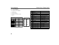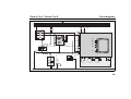
1
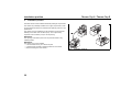
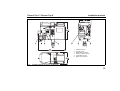
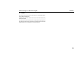
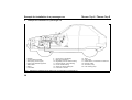
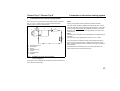
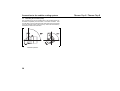
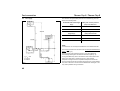
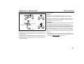
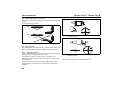
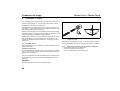
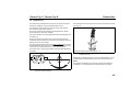
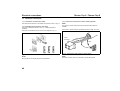
Thermo Top C / Thermo Top E
1
Statutory regulations governing installation
Statutory regulations governing installation
1.1. Statutory regulations governing installation
The Thermo Top C and Thermo Top E heaters have been type-tested
and approved in accordance with EC Directives 72/245/EEC (EMC) and
2001/56/EC (heater) with the following EC permit numbers:
e1* 72/245*95/54*1232*02
e1*2001/56*0002*00
e1*2001/56*0003*00
Installation is governed above all by the provisions in Annex VII of
directive 2001/56/EC.
NOTE:
The provisions of these Directives are binding within the territory
governed by EU Directive 70/156/EEC and should similarly be observed in countries without specific regulations.
(Extract from Directive 2001/56/EC Annex VII)
1.7.1. A clearly visible indicator within the user's field of vision must
show when the heater is switched on or off.
2. Regulations for installation in the vehicle
2.1. Scope
2.1.1. Subject to the provisions of para. 2.1.2, internal combustion
heaters must be installed in accordance with the requirements
contained in the present Annex.
2.1.2. In the case of vehicles of class O (trailers) with heaters for liquid
fuel, it is presumed that these vehicles comply with the requirements in
the present Annex.
2.2. Position of the heater
2.2.1. Parts of the vehicle body and other components in the immediate
vicinity of the heater must be protected against excessive heat and the
danger of contamination by fuel or oil.
2.2.2. The internal combustion heater must not pose a fire hazard even
when overheated. This requirement is deemed to have been met if care
is taken during installation to ensure an adequate distance from all parts,
as well as adequate ventilation and if fire-resistant materials or heat
shields are used.
2.2.3. In vehicles of classes M2 and M3, the heater must not be installed
in the passenger compartment. However, it is permissible to use a unit
in a tightly sealed enclosure which also meets with the conditions in
para. 2.2.2.
2.2.4. The plate in accordance with para. 1.4 (rating plate) or a duplicate
thereof (duplicate rating plate) must be fitted in such a way that it is still
clearly legible when the heater has been installed in the vehicle.
2.2.5. When positioning the heater, all due precautions must be taken
to minimize all risk of bodily injury, as well as damage to items in the
vehicle.
2.3. Fuel supply
2.3.1. The fuel filler neck must not be located in the passenger
compartment and must have a tightly fitting cap to prevent any fuel
leakages.
2.3.2. The type of fuel and the fuel filler neck must be clearly identified
on heaters for liquid fuel, in which the fuel supply is separate from the
fuel supply for the vehicle.
2.3.3. A sign must be affixed to the fuel filler neck warning that the
heater must be switched off before refuelling. A corresponding warning
must also be included in the manufacturer's operating instructions.
29
Statutory regulations governing installation
2.4. Exhaust system
2.4.1. The exhaust outlet must be positioned in such a way that exhaust
gases cannot enter the vehicle via ventilation devices, hot-air inlets or
window openings.
2.5. Combustion air inlet
2.5.1. The air for the combustion chamber of the heater must not be
extracted from the passenger compartment of the vehicle.
2.5.2. The air inlet must be positioned in such a way that it cannot be
obstructed by other objects.
2.6. Heating air inlet
2.6.1. The supply of heating air must consist of either fresh air or
recirculated air and must be taken from a clean area which cannot be
contaminated by exhaust fumes from the engine, the internal
combustion heater or any other source in the vehicle.
2.6.2. The inlet line must be protected by a grating or other appropriate
means.
Thermo Top C / Thermo Top E
IMPORTANT:
Non-compliance with the installation instructions and the warnings
contained therein will lead to the exclusion of all liability by Webasto.
The same also applies if repairs are not undertaken by professionals or
without using genuine spare parts. This invalidates the type approval for
the heater and its homologation / EC type permit.
NOTE:
Contrary to the provisions of para. 2.2.3, the heater may not be installed
in the passenger compartment of vehicles of classes M1 and N.
However, it is permissible to use a unit in a tightly sealed enclosure
which also meets with the conditions in para. 2.2.2.
1.2.
General requirements
1.2.1.
Exhaust emissions
Exhaust lines must be routed at a sufficient distance (at least 20 mm)
from all heat-sensitive vehicle parts (underbody protection,
plastic parts, …).
2.7. Heating air outlet
2.7.1. Hot-air lines within the vehicle must be routed or protected in
such a way as to exclude all risk of injury or damage due to direct
contact.
2.7.2. The air outlet must be arranged or protected so that it cannot be
obstructed by other objects.
2.8. Automatic control of the heating system
When the engine stops, the heating system must switch off
automatically and the fuel supply must be interrupted within 5 seconds.
The heating system may remain in operation if a manual unit has
already been activated.
30
1.2.2.
Fuel lines
Fuel lines must always be routed through cool areas in order to prevent
the formation of bubbles due to heating up.
Thermo Top C / Thermo Top E
2
Use / version
Use / version
2.1. Use of the water heaters
The Webasto Thermo Top C and E water heaters are used in
combination with the onboard heating system
– to heat the passenger compartment,
– to defrost the vehicle windows and
– to preheat water-cooled engines.
2.2. Version
Thermo Top C - B auxiliary heating
Water heater for "petrol" fuel
Thermo Top C - D auxiliary heating
Water heater for "diesel" fuel
The water heaters operate independently of the engine and are
connected to the cooling system, the fuel system and the electrical
system of the vehicle.
Thermo Top C - PME auxiliary heating
Water heater for "biodegradable diesel" fuel
Thermo Top E - B auxiliary heating
Water heater for "petrol" fuel
Thermo Top E - D auxiliary heating
Water heater for "diesel" fuel
The Thermo Top C and Thermo Top E water heaters are designed for
12 Volt operation.
31
Installation position
3
Thermo Top C / Thermo Top E
Installation position
The water heater must be installed outside the passenger compartment.
The heaters are preferably installed in the engine compartment, under
the front fender where they are protected from splashing water or on the
splashboard.
The heaters must be installed as low as possible to permit automatic
bleeding of the heater and circulation pump. This is particularly
important as the circulation pump is not self-priming.
IMPORTANT:
The openings of the water ports must not point downwards in any
installed position.
IMPORTANT:
The heaters must not be installed:
– in the immediate vicinity of or above hot parts,
– in areas directly exposed to splashing water from the wheels,
– below the fording line of the vehicle.
32
Fig. 1:
Installation positions
Thermo Top C / Thermo Top E
Installation position
1
2
3
4
5
6
Fig. 2:
Circulation pump
Fuel filler neck
Water outlet connector
Exhaust outlet connector
Combustion air inlet
Water inlet connector
Installation drawing for Thermo Top E and Z/C
33
Rating plate
4
Rating plate
The rating plate must be positioned so that it cannot be damaged and
must still be clearly legible when the heater is installed (otherwise a
duplicate rating plate must be used).
Inapplicable years must be erased from the rating plate.
34
Thermo Top C / Thermo Top E
Thermo Top C / Thermo Top E
5
Holder
Holder
The holder must be secured to the car body or an intermediate holder
with at least four M6 screws.
Washers with a minimum diameter of 22 mm must be used if the body
surfaces are plane.
The holder must not be secured to the car body with self-tapping screws.
The holder must be correctly machined in compliance with the minimum
bending radii and in accordance with the technical rules.
35
Example for installation in a passenger car
6
1
2
3
4
5
6
7
Example for installation in a passenger car
Radiator
Cooling water thermostat
Water pump (of the engine)
Engine with standard equipment
Water heater
Battery
Fuse holder
Fig. 3:
36
Thermo Top C / Thermo Top E
8
9
10
11
12
13
14
Control unit (in the heater)
Relay (for vehicle fan)
Regulating valve for vehicle heating
Heat exchanger, vehicle heating
Fan for vehicle heating
Switch for vehicle heating fan
Fuse bank in vehicle
Example for installation of the Thermo Top C or E heater in a passenger car
15
16
17
18
19
20
Timer
Fuel pickup
Intake silencer, combustion air intake line
Exhaust muffler
Circulation pump
Fuel metering pump
Thermo Top C / Thermo Top E
7
Connection to the vehicle cooling system
Connection to the vehicle cooling system
The heaters are connected to the vehicle cooling system as shown in
Figs. 3, 4 and 5. At least 4 litres of coolant must be circulated
(Thermo Top C); 3 litres for Thermo Top E.
1
7
2
ϑ
3
4
The water hoses supplied by Webasto must always be used. If other
hoses are used, they must at least comply with DIN 73411. The hoses
must be routed without kinking and preferably uphill to ensure perfect
bleeding. Hose connections must be supported by hose clips so they
cannot slip off.
5
6
1
2
3
4
5
6
7
Equalizing reservoir
Thermostat
Engine
Circulation pump
Heater
Heat exchanger
Radiator
Fig. 4:
NOTE:
Leaking cooling water must be collected in a suitable container.
NOTE:
The hose clips on the heater must be fitted between the flared neck and
the heater.
The hose clips must be tightened with a torque of 2.0 + 0.5 Nm.
Care must be taken to bleed the cooling system before the heater is
taken into service for the first time or after refilling with fresh cooling
water. Heater and lines should be installed in such a way as to ensure
static bleeding.
Malfunctions due to overheating may occur during operation if the
heater and lines have not been bled correctly.
Installation in engine water circulation,
"in-line integration"
The heater must be integrated into the cooling circuit in the feed line to
the on-board heat exchanger.
37
Connection to the vehicle cooling system
7.1. Relocating the circulation pump
The circulation pump can be installed either in its intended position on
the heater or separately from the heater, in the water circulation. Care
must be taken to ensure without fail that water flows through the heater
in the right direction (water outlet at the top / water inlet at the bottom),
otherwise the heater will malfunction.
Fig. 5:
38
Circulation pump U4847
Installation positions
Thermo Top C / Thermo Top E
Thermo Top C / Thermo Top E
8
Fuel connection
Fuel connection
8.1. Fuel connection without non-return valve in tank
The fuel supply for the heater is connected in the return line as shown
in Fig. 3.
8.2.
Fuel connection with non-return valve in tank or fuel
connection for single-line fuel supply
The tank connector with 90° outlet is installed in the tank fitting (Fig. 6).
Fig. 6:
Tank fitting with 90° outlet
39
Fuel connection
8.3.
Fuel supply .
Thermo Top C / Thermo Top E
The values for the permissible pressure at the fuel delivery point are
listed in the following table.
Permissible fuel inflow height
H (m)
Max. perm. excess pressure
(bar) in the fuel line l1
0.00
0.2
1.00
0.11
Permissible fuel suction
height S (m)
Max. perm. negative pressure
(bar) in the fuel tank
0.00
-0.10
0.50
-0.06
1.00
-0.02
NOTE
A fuel feed line can normally be identified from the installed fuel filter.
Fuel may only be taken from the return line with the special Webasto fuel
pickup (see Fig. 8).
The fuel pickup must be fitted so that any air or gas bubbles are
automatically discharged in the direction of the tank (see Fig. 8).
l1 + l2 ≤ 7 m
l1 ≤ 1.2 m
l2 ≤ 5.8 m
Fig. 7:
40
Fuel supply
Air or gas bubbles may arise in the fuel line of the vehicle if there are
leaks in the carburetor or vehicle fuel pump or if the ambient
temperature is higher than the evaporation temperature of the fuel.
The fuel pickup should not be located near the engine, as gas bubbles
may form in the lines on account of heat radiated from the engine. This
may cause problems during combustion.
Thermo Top C / Thermo Top E
Fuel connection
8.4.
Fuel lines
NOTE:
The hose clips must be tightened with a torque of 1.0 + 0.4 Nm.
Leaking fuel must be removed before starting the engine or heater.
Only steel, copper and plastic lines of plasticized, light and temperaturestabilized PA 11 or PA 12 (e.g. Mecanyl RWTL) in accordance with
DIN 73378 may be used for the fuel lines.
to engine
from tank
Fig. 8:
to metering pump
Webasto fuel pickup
When installing the heater in a vehicle with fuel injection system, it is
therefore important to establish whether the fuel pump is located inside
or outside the tank.
If the fuel pump is located inside the tank, fuel can only be withdrawn
from the return line. In this case, it must be ensured that the return line
continues almost to the bottom of the tank. The return line must be
extended if necessary.
IMPORTANT:
If PME (vegetable oil methyl ester) is used as fuel, care must be taken
to ensure that the fuel lines and fuel filter are resistant to PME.
Since the lines normally cannot be routed with a constant uphill gradient,
the inside diameter must not be allowed to exceed a certain size. Air or
gas bubbles will accumulate in lines with an inside diameter of more
than 4 mm and cause malfunctions if the lines sag or run downwards.
The diameters specified in Fig. 7 will ensure that bubbles do not form.
The lines should not be routed downwards from the metering pump to
the heater.
Unsupported fuel lines must be secured to prevent them sagging. They
must be installed in such a way that they cannot be damaged by flying
chippings and high temperatures (exhaust line).
41
Fuel connection
Thermo Top C / Thermo Top E
8.5. Connecting two pipes and a hose
The correct procedure for connecting fuel lines with hosing is illustrated
in Fig. 9.
Thermo Top C / Thermo Top E - petrol
Ensure that there are no leaks!!
Preferably
15° - 90°
Right
Clip
Wrong
Bubble
Fig. 9:
Bubble
Fig. 10: Metering pump DP 2
Installation position
Thermo Top C / Thermo Top E - diesel
Pipe / hose connection
8.6. Metering pump
The metering pump is a combined delivery, metering and shutoff system
and is subject to specific installation criteria (see Figs. 7, 10 and 11).
8.6.1.
Installation position
Before installing the metering pump, ensure that the maximum pressure
occurring at the pickup point is less than 0.2 bar.
It is advisable to install the metering pump in a cool place. The
permissible ambient temperature must not exceed +20 °C at any time
during operation.
Metering pump and fuel lines must not be installed within range of
radiated heat from hot vehicle parts. A heat shield must be used if
applicable.
42
Fig. 11: Metering pump DP 30
Installation position
The pump should preferably be installed near the tank.
Thermo Top C / Thermo Top E
Fuel connection
8.6.2.
Installation and attachment
The metering pump must be secured with a vibration-damping
suspension. Its installation position is limited as shown in Figs. 10
and 11 in order to ensure effective auto-bleeding.
8.7. Sticker
The sticker "Switch off heater before refuelling" must be affixed at a
suitable point.
43
Combustion air supply
9
Thermo Top C / Thermo Top E
Combustion air supply
The intake opening for combustion air must be located so that it cannot
become clogged with dirt. It must not point in the direction of travel.
An intake line is required for combustion air.
The withdrawal point for the combustion air must be located in a cool
(temperature ≤ 20 °C) place where it is protected from splashing water
and above the fording line of the vehicle.
Under no circumstances may the combustion air be taken from areas
occupied by people. A ventilation opening measuring at least 3 cm² is
required if the heater is installed in an enclosed box.
If the heater is installed in a common installation space near the vehicle
tank, the combustion air must be taken in from the outside and the
exhaust gas discharged into the atmosphere. The openings must be
splash-proof.
9.1. Air intake silencer
The air intake silencer must be installed in a position between 0° and 90°
pointing downwards.
Installation instructions
Connect the slotted side (approx. 18 mm) of the combustion air intake
line, max. 400 mm long, to the air intake port of the heater and secure it
with the hose clip supplied.
Turn the air intake silencer as far as possible into the unslotted end of
the air intake line (it need not be secured additionally by means of a
hose clip).
IMPORTANT:
Ensure an adequate distance from the exhaust system.
44
0-90°
0-90°
Fig. 12: Air intake silencer
Installation position
Depending on the installation situation, the air intake silencer must be
secured at a suitable point with the enclosed mounting clip or cable ties.
9.1.1.
Securing the air intake silencer with the mounting clip
– Drill a hole dia. 6.5 mm at a suitable point.
– Press the mounting clip into the hole.
– Fit the air intake silencer in the mounting clip.
Thermo Top C / Thermo Top E
10
Exhaust line
Exhaust line
The exhaust line (inside diameter 22 mm) can be routed with several
bends (270° altogether, minimum bending radius 50 mm).
The opening of the exhaust pipe must not point in the direction of travel
(see Fig. 14).
The total length of the exhaust line must be not less than 500 mm.
The maximum length equals 1000 mm.
The exhaust muffler should preferably be installed near the heater,
but at least 200 mm away from the latter.
The exhaust muffler must not be installed near the intake opening for the
combustion air.
The exhaust muffler and exhaust line must not be secured to heatsensitive parts of the vehicle and must be kept at an adequate minimum
distance of 20 mm from the latter.
The opening of the exhaust pipe must be freely accessible and must not
be directed towards any part of the vehicle. The exhaust pipe opening
must remain at a sufficient distance (≥ 0.2 m) from the ground.
The Thermo Top C / Thermo Top E heater must not be operated without
the muffler.
6.5
Discharge direction almost vertical 90° ± 10°
Fig. 14: Exhaust pipe opening
Installation position
Rigid pipes of unalloyed steel with a minimum wall thickness of 1.0 mm
or flexible piping of alloyed steel only must be used as exhaust line.
NOTE:
Accumulated condensation in the exhaust line must be discharged
immediately. A condensate drain hole may be drilled if necessary.
Fig. 13: Exhaust muffler
Direction of flow as desired
45
Electrical connections
11
Thermo Top C / Thermo Top E
Electrical connections
11.1. Connection of control unit / heater
The electrical connections on the heater are made as shown in Fig. 17.
11.2. Installation and connection of the timer
The timer is installed as shown in Fig. 15. A drilling template is
enclosed.
11.3. Connection of the summer / winter switch (optional)
NOTE:
The summer / winter switch cannot be connected if the Telestart is
installed.
The summer / winter switch is connected as shown in Figs. 16 and 17.
The timer is connected as shown in the circuit diagram in Fig. 17.
Timer
connector
vi
br
Strip
S5
Fig. 15: Timer installation
NOTE:
Do not press on the display panel during installation.
46
Fig. 16: Connection of the summer / winter switch
NOTE:
The ends of lines br and vi are inserted in the insulating hose!
Thermo Top C / Thermo Top E
Electrical connections
11.4. Vehicle fan
The vehicle fan is controlled via the vehicle fan relay, see circuit diagram
in Fig. 17.
NOTE:
The connection in the control unit (heating) is dimensioned for one fan
relay (I max = 0.5 A).
11.5. Installation of Telestart (optional)
The Telestart is installed in accordance with its installation instructions.
Proceed as directed in the operating and maintenance instructions to
learn in the Telestart transmitter.
11.6. Installation of Thermo Call (optional)
The Thermo Call is installed in accordance with the Thermo Call
installation instructions.
47
Circuit diagrams
12
Thermo Top C / Thermo Top E
Circuit diagrams
12.1. Legend for circuit diagrams:
Troubleshooting
Outside temperature
Vehicle fan fuse installed in vehicle
Optional
Cable cross-sections
48
< 7.5 m
7.5 - 15 m
0.5 mm2
0.75 mm2
0.75 mm2
1.5 mm2
1.0 mm2
1.5 mm2
1.5 mm2
2.5 mm2
2.5 mm2
4.0 mm2
4.0 mm2
6.0 mm2
Cable colours
bl
br
ge
gn
gr
or
rt
sw
vi
ws
blue
brown
yellow
green
grey
orange
red
black
violet
white
Item
A1
A2
A3
B2
E
F1
F2
F3
H1
K3
M1
M2
M3
P
S1
S2
S5
X1
X2
X3
X4
X5
X6
X9
Y1
Designation
Heater
Control unit
Connecting box
Temperature sensor
Glow plug / flame monitor
Fuse 20A
Fuse 1A
Fuse 25A
LED (in pos. P)
Relay
Motor
Motor
Motor
Timer, digital
Switch for vehicle fan
Switch for vehicle fan
Switch
Plug connection, 6-pole
Plug connection, 2-pole
Plug connection, 2-pole
Plug connection, 2-pole
Plug connection, 2-pole
Plug connection, 2-pole
Plug connection, 4-pole
Metering pump
Comment
Thermo Top E or Z/C
Flat fuse DIN 72581 Part 3
Flat fuse DIN 72581 Part 3
Flat fuse DIN 72581 Part 3
Switch-on indicator
Vehicle fan
Combustion air fan
Circulation pump
Vehicle fan
For programmed operation
S1 or S2 depending on vehicle
S1 or S2 depending on vehicle
Summer / winter switch
Water-repellent
Water-repellent
Water-repellent
Water-repellent
Water-repellent
Water-repellent
Thermo Top C / Thermo Top E
Circuit diagrams
X9
(75) 15
30
61
rt
ϑ
2
1
F1
ge
sw
3
A3
rt
F2
2
X1
rt
sw
+
3
A2
1
rt
OUT
+15
rt
P
-
I max. = 0.5 A
gn/ws
86
87
85
4
87a
K3
1
X3
2
1
2
1 2
1
2
X2
1
2
B
X6
X5
X4
5
A
X9
H1
C
F3
6
30
br
br
br
X1
1
sw
1
2
3
4
5
6
bl
2
X2
M
Ventilation
Heating
vi
br
M3
Y1
S2
E
4
2
1
X3
X4
2
1
X5
M
M1
2
M
ϑ
M2
B2
A1
br
S5
br
1
S1
31
Fig. 17: Automatic circuit for Thermo Top C and E, 12 V timer (legend see page 48)
49
Initial start-up
13
Initial start-up
NOTE:
The safety instructions in the operating and maintenance instructions
must be observed without fail.
The operating and maintenance instructions must be read through
without fail before starting the heater.
After installing the heater, the water circulation and fuel supply system
must be carefully bled, taking into account the directions of the vehicle
manufacturer.
All water and fuel connections must be checked for leaks and secure
attachment during a trial run of the heater. If the heater switches to fault
mode during operation, the fault must be located and remedied.
50
Thermo Top C / Thermo Top E
Thermo Top C / Thermo Top E
14
Faults
Faults
14.1. Fault lock-out due to faults in the heater
Fuel is supplied for max. 180 seconds if the flame does not start to burn.
Fuel is supplied for max. 85 seconds if the flame goes out during
operation.
The fuel supply is shut off immediately if the system overheats
(temperature limiter is tripped).
In all cases (except a fault in the combustion air fan), the heater
continues to run for 120 seconds after a fault lock-out. The run-on
time may vary, depending on the software version in the control
unit.
IMPORTANT:
A warning is not displayed following a fault lock-out due to overheating.
14.2. Cancelling the fault lock-out
The fault lock-out is cancelled as described in the operating and
maintenance instructions.
51
Technical data
15
Thermo Top C / Thermo Top E
Technical data
15.1. Technical data, Thermo Top C
Except where limit values are specified, the technical data on the right
refer to the usual heater tolerances of ± 10% at an ambient temperature
of +20 °C and at nominal voltage.
15.1.1. Fuel for Thermo Top C (petrol)
The fuel specified by the manufacturer may be used.
15.1.2. Fuel for Thermo Top C (diesel)
The diesel fuel specified by the manufacturer may be used. When
changing over to low-temperature fuel, the heater must be operated for
approx. 15 minutes so that the fuel line and fuel pump are also filled with
the new fuel.
Negative influences due to additives are not known.
Circulation pump
Flow rate at 0.1 bar
Nominal voltage
Operating voltage range
4847
900 l/h
12 V
10.5 ... 15 V
Nominal power consumption
14 W
Dimensions, circulation pump
Width 214 mm
Height 106 mm
Weight 168 mm
Weight
52
0.3 kg
Thermo Top C / Thermo Top E
Heater
Technical data
Operation
Thermo Top C - B
Thermo Top C - D
EC approval mark
Type
Heat output
Water heater with evaporator-type burner
Full load
Part load
Fuel
Fuel consumption
Thermo Top C - D
e1
5.2 kW
2.5 kW
Petrol
Full load
Part load
Diesel
0.70 l/h
0.34 l/h
0.61 l/h
0.30 l/h
Nominal voltage
Operating voltage range
12 V
10,5 ... 15 V
Nominal power consumption without circulation pump Full load
(without vehicle fan)
Part load
Perm. ambient temperature:
Heater:
- Operation
- Storage
Metering pump: - Operation
Perm. operating pressure (heat carrier)
28 W
18 W
-40° ... +60°C
-40° ... +120°C
-40° ... +20°C
-40° ... +60°C
-40° ... +120°C
-20° * ... +20°C
0.4 ... 2.5 bar
Capacity of the heat exchanger
0.15 l
Minimum capacity of the circulation
4.00 l
Minimum flow rate for the heater
CO2 in the exhaust gas (perm. function range)
Heater dimensions
(tolerance ± 3 mm)
Weight
Diesel/PME
250 l/h
8 ... 12.0% by vol.
Width 214 mm
Height 106 mm
Weight 168 mm
2.9 kg
* May only be operated with diesel / PME mixture containing < 50% PME.
53
Technical data
Thermo Top C / Thermo Top E
15.2. Technical data, Thermo Top E
Except where limit values are specified, the technical data on the right
refer to the usual heater tolerances of ± 10% at an ambient temperature
of +20 °C and at nominal voltage.
15.2.1. Fuel for Thermo Top E (petrol)
The fuel specified by the manufacturer may be used.
15.2.2. Fuel for Thermo Top E (diesel)
The diesel fuel specified by the manufacturer may be used. When
changing over to low-temperature fuel, the heater must be operated for
approx. 15 minutes so that the fuel line and fuel pump are also filled with
the new fuel.
Negative influences due to additives are not known.
Circulation pump
Flow rate at 0.1 bar
Nominal voltage
Operating voltage range
4847
900 l/h
12 V
10.5 ... 15 V
Nominal power consumption
14 W
Dimensions, circulation pump
Width 214 mm
Height 106 mm
Weight 168 mm
Weight
54
0.3 kg
Thermo Top C / Thermo Top E
Heater
Technical data
Operation
Thermo Top E - B
EC approval mark
Type
Heat output
Water heater with evaporator-type burner
Full load
Part load
Fuel
Fuel consumption
Full load
Part load
4.2 kW
2.5 kW
Petrol
Diesel
0.56 l/h
0.34 l/h
0.49 l/h
0.30 l/h
Nominal voltage
12 V
Operating voltage range
Nominal power consumption without circulation pump
(without vehicle fan)
Thermo Top E - D
e1
10.5 ... 15 V
Full load
Part load
Perm. ambient temperature:
Heater:
- Operation
- Storage
Metering pump: - Operation
Perm. operating pressure (heat carrier)
Capacity of the heat exchanger
23 W
18 W
-40° ... +60°C
-40° ... +120°C
-40° ... +20°C
-40° ... +60°C
-40° ... +120°C
-20° ... +20°C
0.4 ... 2.5 bar
0.15 l
Minimum capacity of the circulation
3.00 l
Minimum flow rate for the heater
250 l/h
CO2 in the exhaust gas (perm. function range)
Heater dimensions
(tolerance ± 3 mm)
Weight
8 ... 12.0% by vol.
Width 214 mm
Height 106 mm
Weight 168 mm
2.9 kg
* May only be operated with diesel / PME mixture containing < 50% PME.
55
Technical data
56
Thermo Top C / Thermo Top E