1
Product Manual
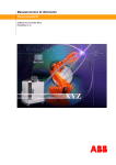
Welding Equipment A314E/A316E/A324E-L
IRC5 Design 2006
3HEA 802 347-002, Rev.- 2006-03
The information in this manual is subject to change without notice and should not be construed as a commitment by ABB. ABB assumes no responsibility for any errors that may appear in this manual.
Except as may be expressly stated anywhere in this manual, nothing herein shall be construed as any
kind of guarantee or warranty by ABB for losses, damages to persons or property, fitness for a specific
purpose or the like.
In no event shall ABB be liable for incidental or consequential damages arising from use of this manual
and products described herein.
This manual and parts thereof must not be reproduced or copied without ABB's written permission, and
contents thereof must not be imparted to a third party nor be used for any unauthorized purpose. Contravention will be prosecuted.
Additional copies of this manual may be obtained from ABB at its then current charge.
© 2006 ABB Automation Technologies AB
ABB Automation Technologies AB
Robotics & Manufacturing
SE-69582 Laxå
Sweden
Contents
Product Manual
Welding
Equipment
IRC5, Design
2006
Specification
Tab 1:
Introduction
1
Safety instructions
3
System Description
9
Components
Installation and operation
Installation and set-up
13
Tab 2:
1
Operation
23
Diagnostics, fault handling
27
Maintenance
Tab 3:
Maintenance
1
Repairs
5
Process unit PIB
Tab 4:
Process control equipment
1
Technical specification
3
Safety
5
Configuration
3HEA 802 347-002, Rev.- 2006-03
15
i
Installation
17
Operation and connections
19
ii
3HEA 802 347-002, Rev.- 2006-03
Specification
Tab 1:
Specification
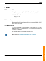
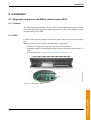
1 Introduction
1
1.1 General
1
1.2 Definitions
2
2 Safety instructions
3
2.1 Description
3
2.2 Warning symbols (signals)
4
2.2.1 DANGER – Ensure that the main power switch is turned off. 5
2.2.2 WARNING – The unit is sensitive to ESD.
7
3 System Description
9
3.1 General
9
3.2 Equipment
10
3.3 Principal layout
11
3.3.1 Example of system solution
12
4 Components
13
4.1 General
13
4.2 Wire feed system A314E/316E/324E
14
4.2.1 General
4.2.2 Wire feed unit
4.2.3 Operating and indicating devices on the wire feeder unit
4.3 Process control equipment
4.3.1
4.3.2
4.3.3
4.3.4
3HEA 802 347-002, Rev.- 2006-03
14
15
16
17
General
Process unit (PIB)
Connections on control equipment for process equipment
Connections in control equipment for process equipment
17
18
19
20
Specification i
Specification
Specification ii
3HEA 802 347-002, Rev.- 2006-03
General
1 Introduction
1.1 General
About this manual
This manual provides information on:
• Welding equipment, including control equipment.
• Mechanical/electrical installation.
• Operation.
• Repair/maintenance.
Operation
This manual is intended for use in conjunction with:
• Installation
• Operation
• Maintenance
• Repairs
• Training
Who should read this manual?
This manual is intended for:
• Operators
• Installation personnel
• Repair and maintenance personnel
Basic knowledge
Readers of this manual must be...
• familiar with industrial robots and the relevant terminology
• Familiar with the equipment.
• Skilled in mechanical and electrical installation/maintenance/repairs.
3HEA 802 347-002, Rev.- 2006-03
1-1
Specification
Introduction
Specification
Introduction
Definitions
Reference documents
Document
Described in:
Robotics manuals
System manual for arc welding robot systems
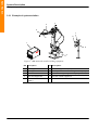
1.2 Definitions
ABB IRC5
Controller
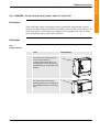
Control system ABB IRC5 Controller is available in two basic versions:
• Single cabinet and dual cabinet.
Designation
Description
Illustration
SCC,
On the single cabinet version, all components are
Single cabinet located in a single cabinet.
In this manual, the single cabinet version is referred
to as SCC.
DCC,
Dual cabinet
On the dual cabinet version, components are
located in two modules:
1. A control module
2. A drive module
In this manual, the dual cabinet version is referred to
as DCC.
1-2
Figure 1 SCC
1
2
Figure 2 DCC
3HEA 802 347-002, Rev.- 2006-03
Description
2 Safety instructions
A robot is quick and powerful. An interruption in service or a stop can be followed
by quick and hazardous movement. Even if the robot’s motion pattern is predetermined, an external signal can influence the motion sequence and cause an
unexpected movement. It is therefore important that all safety instructions are
observed when entering a safety supervised area.
2.1 Description
Safety instructions can be found under tab 1 in the AW system manual for all steps
that involve risk for personal injury or material damage. In addition, they are printed
out by the instruction for each step.
General warnings where the intention is to avoid problems are only indicated at the
pertinent instruction.
All personnel working with the welding robot system must have a full understanding of the
applicable safety instructions.
Reference documents
Document
Described in:
Related safety instructions.
AW System manual, chapter introduction
and safety.
3HEA 802 347-002, Rev.- 2006-03
1-3
Specification
Safety instructions
Specification
Safety instructions
Warning symbols (signals)
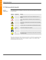
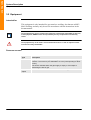
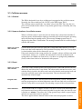
2.2 Warning symbols (signals)
Symbol
explanations
The different types of warnings are indicated in the following chapters according to
the table below:
Symbol Designation
Meaning
Danger
Warning that serious or fatal personal injury and/or serious
damage to the product will occur if the instructions are not
followed.
Warning!
Warns of the risk of personal injury or serious damage to the
product. Always follow the instructions that accompany this
symbol.
Electric shock
Warns of possible electric shock that can cause serious or fatal
personal injury. Always follow the instructions that accompany
this symbol.
Caution
Draws your attention to the fact that damage to the product may
occur if an action is not performed or is performed incorrectly.
Static
electricity,
ESD
The ESD symbol indicates a risk of static electricity that may
cause serious damage to the product.
Note:
Information about important parts.
Tips
This symbol refers to an instruction providing further information
on a particular topic.
!
The safety information in the document must not be considered as a guarantee from
ABB that the equipment cannot cause accidents or injury, even if all the safety
instructions have been observed.
1-4
3HEA 802 347-002, Rev.- 2006-03
DANGER – Ensure that the main power switch is turned off.
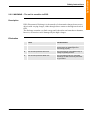
2.2.1 DANGER – Ensure that the main power switch is turned off.
Description
Work with high voltage installations entails a potentially lethal hazard. Persons
subjected to high voltages can suffer heart failure, burns or other serious injuries. To
avoid such injuries, never begin a job without first eliminating the risks to safety.
How to eliminate safety risks is descried below.
Elimination
SCC
(single cabinet)
Action
1.
2.
SCC (single cabinet)
Turn off the main power switch on
the SCC (single cabinet).
The main power switch turns off
incoming power to the cabinet and
operating power to all included drive
modules.
DM (drive module)
Turn off the main power switch
(operating switch) on the respective
drive modules to switch off incoming
power.
3HEA 802 347-002, Rev.- 2006-03
Info/Illustration
1
2
1-5
Specification
Safety instructions
Specification
Safety instructions
DANGER – Ensure that the main power switch is turned off.
DCC
(dual cabinet)
Action
Info/Illustration
1.
CM (control module)
Turn off the main power switch at the 1
control module.
The main power switch on the
control module turns off operating
power to all included drive modules.
2.
DM (drive module)
Turn off the main power switch
(operating switch) on the respective
drive modules to switch off incoming
power.
2
All power is disconnected when the main
power switch on the drive module (DM1) is
turned off.
1-6
3HEA 802 347-002, Rev.- 2006-03
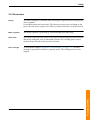
WARNING – The unit is sensitive to ESD.
2.2.2 WARNING – The unit is sensitive to ESD.
Description
ESD (Electrostatic Discharge) is the transfer of electrostatic charges between two
objects with varying charges, either through direct contact or through an electrical
field.
The discharge contains very little energy and is therefore not hazardous to humans,
however, electronics can be damaged by the high voltages.
Elimination
Action
Info/Illustration
1.
Use an ESD bracelet.
The bracelet must be regularly tested to
ensure that it is undamaged and
functioning properly.
2.
Use an ESD-protected floor mat.
The mat must be grounded through a
voltage regulating resistor.
3.
Use an ESD-protected table mat.
The mat shall produce a controlled
discharge of static electricity and must
be grounded.
3HEA 802 347-002, Rev.- 2006-03
1-7
Specification
Safety instructions
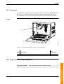
WARNING – The unit is sensitive to ESD.
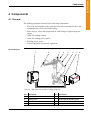
Location of attachment point for ESD bracelet
Single cabinet
Location in the SCC (single cabinet) is shown in the figure below.
3HEA802157-001(L-typ).wmf
A
Figure 3 Location of attachment point for ESD bracelet
Pos. Description
A
Attachment point for ESD bracelet in the SCC (single cabinet)
The attachment point (A/B) for the ESD bracelet is located on the computer unit in
the SCC (single cabinet)/DCC (dual cabinet).
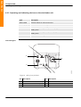
Dual cabinet
Location in the DCC (dual cabinet) is shown in the figure below.
A
B
xx0400001061
Specification
Safety instructions
Figure 4 Location of attachment point for ESD bracelet
Pos. Description
1-8
A
Attachment point for ESD bracelet in the control module
B
Attachment point for ESD bracelet in the drive module
3HEA 802 347-002, Rev.- 2006-03
General
3 System Description
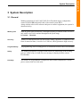
3.1 General
Welding equipment A314E/316E/324E (E for Extended range) is adapted for
control of robot IRB1400/1600/2400, with control system IRC5.
Along with the robot's AW software and process control equipment, the system is
characterized by;
Working area
With an optical pulse tachometer, with high frequency resolution in the wire feed
unit, stable wire feed is attained throughout the speed range:
0.3 m/min – 30 m/min.
Accuracy
Transfer of information between robots and welding equipment is conducted in the
form of numerical data, in serial via a CAN bus, which guarantees high accuracy.
Programmability
All programming of the welding process is conducted from the robot's FlexPendant.
Safety
The welding equipment is equipped with sensors for monitoring of the welding
process. In the event of a fault, an error message is displayed on the robot's
FlexPendant.
Flexibility
The transfer of programmable configuration data enables adaptation to various
power sources and wire feed units.
3HEA 802 347-002, Rev.- 2006-03
1-9
Specification
System Description
Specification
System Description
Equipment
3.2 Equipment
Intended for
This equipment is only intended for gas metal-arc welding, also known as MIG/
MAG welding, and may only be used in accordance with the instructions in the
documentation.
The equipment may only be used for other purposes if specifically stated. With all other use
of the equipment, ABB disclaims all responsibility and any compensation and warranty
claims.
The equipment may not be used in environments where there is a risk of explosion and/or
ones that are easily combustible.
Pressure sensors
Type
Description
Gas sensor
The pressure sensor incorporates an open contract that closes at high
pressure. The sensor is pre-calibrated to 0.2 bar (corresponding to about
5 l/min).
The sensor indicates when the gas supply is empty or if an object is
obstructing the flow of gas.
Water sensor A water sensor is chosen when a water-cooled welding torch is included.
Option
1-10
3HEA 802 347-002, Rev.- 2006-03
Principal layout
3.3 Principal layout
The welding equipment consists of:
Components
Wire feed system
Type
• A314E (for robot IRB 1400)
• A316E (for robot IRB 1600)
• A324E-L_PIB (for robot IRB 2400)
Control equipment for
process equipment
• PIB
Welding power source
• MigRob 500
• RPB 320/420/520
Accessories (process
options)
The following accessories can be purchased for the
welding equipment:
• Welding torch kits (Dinse, Binzel)
• Joint tracker
• Spatter cleaning unit
• Wire cutter
• Automatic TCP measurement, BullsEye
3HEA 802 347-002, Rev.- 2006-03
1-11
Specification
System Description
Specification
System Description
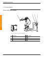
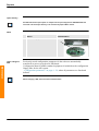
Example of system solution
3.3.1 Example of system solution
4
3
2
7
6
5
1
8
9
Figure 5 IRB 2400 with installed welding equipment
1-12
Pos. Description
Pos. Description
1
Welding power source
6
Wire cutter (process option)
2
Welding torch
7
BullsEye, TCP calibration unit (process option)
3
Hose bundle
8
Spatter cleaning unit (process option)
4
Wire feed equipment
9
Process control equipment
5
Insulator/Collision sensor
(option)
3HEA 802 347-002, Rev.- 2006-03
General
4 Components
4.1 General
The welding equipment consists of the following components:
• Wire feed unit installed on the robot arm and with connection for the torch
• Attachment for wire feed unit and wiring
• Hoses for gas, water and compressed air, and wiring for signal and power
supply
• Cable for welding current
• Cable for welding power source
• Welding power source
• Control equipment for process equipment
Overview figure
1
2
3
4
5
6
7
8
Figure 6 IRB 2400 with installed welding equipment
Pos. Description
Pos. Description
1
Single cabinet/Dual cabinet
5
Wire guide
2
Welding torch
6
Hoses/cable for welding power
3
Wire feed unit
7
Process control equipment
4
Gas/water sensor
8
Welding power source
3HEA 802 347-002, Rev.- 2006-03
1-13
Specification
Components
Specification
Components
Wire feed system A314E/316E/324E
4.2 Wire feed system A314E/316E/324E
4.2.1 General
Two types of wire feed systems are available:
• With bobbin
• With Marathon Pac
The wire feed system is used for gas arc welding.
The system is intended for installation directly on the robot, which entails short hose
bundles with good wire feed, and subsequently, lower demands on floor space.
Bobbin
If bobbin used, it may be necessary to adjust the brake hub. See “Brake hub (bobbin)
adjustment” on page 2 - 21.
Working area
The wire feed system complies with ABB Automation Technologies AB
recommended layout arrangements.
This entails that the robot has a full working area within a sector of ±150° for
A314E/316E/324E, around axis 1.
Considerable caution must be observed when, for example, programming outside the robot's
working area so as not to damage the equipment.
This especially applies to the IRB 1600 and the "bending backwards" movement.
Technical specifications and requirements
1-14
Type
Data
Wire diameter
0.8 mm - 1.6 mm
Max. wire feed speed
30 m/min
Permitted ambient temperature
0ºC - +40ºC
3HEA 802 347-002, Rev.- 2006-03
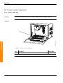
Wire feed unit
4.2.2 Wire feed unit
Overview figure
2
4
1
5
1
3
3
j5000841
6
Figure 7 Wire feed unit
Item Description
Item
Description
1
Upper feed roller
4
Motor
2
Set screw
5
Inlet nozzle
3
Lower feed roller
6
Bolt
Feed rollers
The wire is conveyed by two pairs of feed rollers that are connected to one another.
The two upper rollers (1) are spring loaded.
The power from the motor is transferred to the rollers via a drive on the motor shaft.
The pressure between the upper and lower rollers can be individually adjusted with
set screws (2).
All rollers have slide bearings.
The lower feed rollers (3) have recesses for two different wire diameters. The
recesses are marked with the respective wire diameters.
Motor
The motor (4) is permanently magnetized and equipped with an optical pulse
tachometer for accurate speed control.
When Marathon
Pac is used
When a Marathon Pac is used, an inlet nozzle is fitted (5). The nozzle is secured with
a screw (6).
When a bobbin is
used
When a bobbin is used, the wire guide is installed directly in the wire feed unit and
secured with a screw (6).
3HEA 802 347-002, Rev.- 2006-03
1-15
Specification
Components
Operating and indicating devices on the wire feeder unit
4.2.3 Operating and indicating devices on the wire feeder unit
Type
Description
WIRE FEED
Electrical switch for manual wire feed.
RESET (Option)
Electrical switch for resetting the collision sensor
AIR
Connection for air to welding torch.
IN
Connection for cooling water (blue hose). Applies to water-cooled
welding torch.
OUT
Connection for cooling water (red hose). Applies to water-cooled
welding torch.
Euro connector
Connection for welding torch
Overview figure
1
2
6
5
4
3
j5000842
Specification
Components
Figure 8 Side of wire feed unit
1-16
Pos. Description
Pos. Description
1
Electrical switch “WIRE FEED”
4
Connection “IN”
2
Electrical switch "RESET" option
5
Connection “OUT”
3
Connection “AIR”
6
Euro connector
3HEA 802 347-002, Rev.- 2006-03
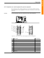
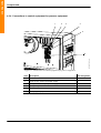
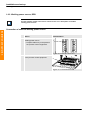
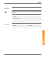
Process control equipment
4.3 Process control equipment
4.3.1 General
Between the IRC5 control system and the included welding equipment, there is a
modularly designed PIB process unit. It is installed on the inside of the control
equipment for the process equipment.
Example of how the process control equipment can be installed, see “Example of
system solution” on page 1 - 12.
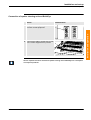
Overview figure
The figure below shows the inside of the control cabinet with units included in the
control equipment for process control equipment.
4
1
3
3HEA802174-001.wmf
2
Figure 9 Process control equipment
Pos. Description
1
Transformer, see “Transformer” on page 4 - 11
2
Process unit PIB
3
Cable entry for connection of welding equipment, see “Cable entries
on the control equipment for process equipment” on page 1 - 19
4
Interlock unit and terminals for welding equipment
3HEA 802 347-002, Rev.- 2006-03
Designation
A121
1-17
Specification
Components
Specification
Components
Process unit (PIB)
4.3.2 Process unit (PIB)
General
The PIB is an I/O unit with an integrated wire feed regulator that communicates
directly with ABB's IRC5 robot control system for control and monitoring of
welding with robots. The process unit includes the hardware and software for
control and regulation of the arc welding equipment.
Connections
The I/O connections on the PIB are grouped, see “Process unit PIB” on page 4 - 1,
for direct cable connection to:
• Welding power source
• Wire feed unit
• Torch cleaner
• Sensors, etc.
1-18
3HEA 802 347-002, Rev.- 2006-03
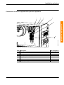
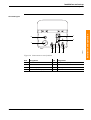
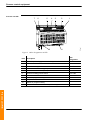
Connections on control equipment for process equipment
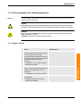
4.3.3 Connections on control equipment for process equipment
The components in the welding equipment are connected to jackable terminals
installed inside the control equipment. Cable entries for cables are on the control
equipment.
Location
The following figure shows the connections on the control equipment.
1
2
10
3
4
5
9
K
DL1/10
K
DL1/10
8
7
6
11
Figure 10 Cable entries on the control equipment for process equipment
Item
Description
1
Welding power source
2
Wire feed unit FEED 2
3
CAN (in)
4
Welding power source, CAN
5
Cooling unit
6
Wire feed unit FEED 1
7
MOTORS ON and feed from drive module
8
Safety signals (in)
9
Spatter cleaning unit or BullsEye SA (stand-alone)
10
Safety signals (out)
11
CAN (out)
3HEA 802 347-002, Rev.- 2006-03
Connected to
A12.K11
A12.X4
A12.X1
1-19
Specification
Components
Connections in control equipment for process equipment
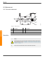
4.3.4 Connections in control equipment for process equipment
1
2
4
3
5
6
3HEA802174-001.wmf
Specification
Components
Figure 11 Connections in control equipment for process equipment
1-20
Item
Description
Item designation
1
Contactor
A12.K1
2
Fuse (3.15 A, 230 V) for power supply
F1
3
Fuse (3.15 A, 230 V) for power supply
F2
4
Safety relay
A12.K11
5
Motors on and feed from DM
A12.X4
6
Safety signals (in)
A12.X1
3HEA 802 347-002, Rev.- 2006-03
Installation and operation
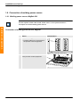
1 Installation and set-up
1
1.1 Transport and unpacking
1
1.2 Lifting instructions
1
1.3 Installation of welding equipment and process options
2
1.3.1 Example of system solution
2
1.4 Installation of process control equipment
1.4.1 Example of system solution
3
1.5 Connection of welding equipment
4
1.5.1 Block diagram
1.5.2 Process control equipment
1.5.3 Wire feed system type A314E/316E/324E
4
5
9
1.6 Connection of welding power source
10
1.6.1 Welding power source, MigRob 500
1.6.2 Welding power source, RPB
10
12
1.7 Accessory connections
14
1.7.1 Welding torch
1.7.2 Cooling unit, OCE 2
1.7.3 Process options
14
16
18
1.8 Configuration of welding equipment
20
1.8.1 General
1.8.2 Installation floppy disk
1.8.3 Reload configuration data
20
20
20
1.9 Brake hub (bobbin) adjustment
21
2 Operation
23
2.1 Inspection before start-up
23
2.2 Start-up
24
2.3 Wire feed
25
2.3.1 Operating mode
2.3.2 Wire feed motor operation in all operating modes
2.3.3 Manual wire feed
3 Diagnostics, fault handling
25
25
26
27
3.1 LEDs on PIB process unit
27
3.2 Upon fault in PIB
28
3.2.1 Acknowledgement of error messages
3.2.2 Error message
28
28
3.3 Collision sensors
29
3.3.1 Error messages during program operation
3HEA 802 347-002, Rev.- 2006-03
3
29
Installation and operation i
Installation and operation
Tab 2:
Installation and operation
Installation and operation ii
3HEA 802 347-002, Rev.- 2006-03
Installation and set-up
Transport and unpacking
1 Installation and set-up
This work may only be carried out by persons trained in the use of the complete system and
who are aware of the special risks involved with these different parts.
1.1 Transport and unpacking
The safety instructions and other instructions must be studied carefully before moving and
unpacking the welding equipment. These can be found under separate tabs in the system
manual.
• Check that the equipment is not damaged in any way.
• Report any visible transport damage immediately.
1.2 Lifting instructions
Lifting of the safety equipment may only be conducted:
• Using equipment that complies with applicable lifting standards.
• By authorized personnel.
Always maintain a safe distance from suspended loads.
3HEA 802 347-002, Rev.- 2006-03
2-1
Installation and operation
Caution must be exercised. All work carried out on the system shall be done professionally
and conform to applicable safety regulations.
Installation and set-up
Installation of welding equipment and process options
1.3 Installation of welding equipment and process options
For descriptions of the component products, see the manuals under the respective tabs in
the system manual.
Installation and operation
1.3.1 Example of system solution
4
3
2
7
6
5
1
8
9
Figure 1 IRB 2400 with installed welding equipment
2-2
Pos. Description
Pos. Description
1
Welding power source
6
Wire cutter (process option)
2
Welding torch
7
BullsEye, TCP calibration unit (process
option)
3
Hose bundle
8
Spatter cleaning unit (process option)
4
Wire feed equipment
9
Process control equipment
5
Insulator/Collision sensor
(option)
3HEA 802 347-002, Rev.- 2006-03
Installation and set-up
Installation of process control equipment
1.4 Installation of process control equipment
1.4.1 Example of system solution
Welding power source, MigRob 500/RPB
2
3
4
5
6
7
8
Installation and operation
1
Figure 2 IRB 2400 with installed welding equipment
Pos. Description
Pos. Description
1
Single cabinet/Dual cabinet
5
Wire guide
2
Welding torch
6
Hoses/cable for welding power
3
Wire feed unit
7
Process control equipment
4
Gas/water sensor
8
Welding power source
3HEA 802 347-002, Rev.- 2006-03
2-3
Installation and set-up
Connection of welding equipment
1.5 Connection of welding equipment
1.5.1 Block diagram
4
STYRUTRUSTNING
SÄKERHET
Installation and operation
4
1
2
STYRUTRUSTNING
PROCESS
SVETSSTRÖMKÄLLA
IRB
IRBP
Figure 3 Block diagram, safety equipment
2-4
Pos. Description
Pos. Description
1
Process control equipment
5
Cooling unit
2
Welding power source
6
BullsEye/TC
3
Wire feed system
7
Safety control equipment
4
Single/Dual cabinet with control
equipment for positioners
3HEA 802 347-002, Rev.- 2006-03
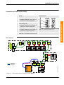
Installation and set-up
Process control equipment
1.5.2 Process control equipment
Location
4
3
3HEA802174-001.wmf
2
Figure 4 Process control equipment
Pos. Description
1
Transformer, see “Transformer” on page 4 - 11
2
Process unit PIB
3
Cable entry for process equipment, see“Cable entries on the control
equipment for process equipment” on page 2 - 6
4
Interlock unit and jackable terminals for process equipment, see
“Connections in control equipment for process equipment” on page
2-7
3HEA 802 347-002, Rev.- 2006-03
Designation
A121
2-5
Installation and operation
1
Installation and set-up
Process control equipment
Cable entries
The following figure shows the cable entries for the control equipment.
10
3
4
5
9
K
DL1
/1
0
K
DL1
/1
0
Installation and operation
1
2
8
7
6
11
Figure 5 Cable entries on the control equipment for process equipment
2-6
Item
Description
Connected to
14
Welding power source
26
Wire feed unit FEED 2
3
CAN (in)
4
Welding power source, CAN
5
Cooling unit
62
Wire feed unit FEED 1
7
MOTORS ON and feed from drive module
8
Safety signals (in)
9
Spatter cleaning unit or BullsEye SA (stand-alone)
10
Safety signals (out)
11
CAN (out)
A12.K11
A12.X4
A12.X1
3HEA 802 347-002, Rev.- 2006-03
Installation and set-up
Process control equipment
Connections in control equipment for process equipment
1
2
4
3
3HEA802174-001.wmf
6
Figure 6 Connections in control equipment for process equipment
Item
Description
Item designation
1
Contactor
A12.K1
2
Fuse (3.15 A, 230 V) for power source
F1
3
Fuse (3.15 A, 230 V) for power source
F2
4
Safety relay
A12.K11
5
Motors on and feed from DM
A12.X4
6
Safety signals (in)
A12.X1
3HEA 802 347-002, Rev.- 2006-03
2-7
Installation and operation
5
Installation and set-up
Process control equipment
Process unit PIB
7
6
5
4
3
2
1
Installation and operation
0
8 9
10
PIB.wmf
1
11
Figure 7 Outlet designations on PIB
2-8
Item
Description
Item
designation
1
Outlet for power source and interlocking
A121.TB1
2
Outlet for CAN bus/DeviceNet
A121.TB2
3
Outlet for welding torch accessories
A121.TB4
4
Outlet for wire feed unit (signal)
A121.TB6
5
Outlet for wire feed unit (motor)
A121.TB5
6
Outlet for welding power source
A121.TB3
7
Outlet
A121.TB11
8
Outlet for program loading
9
Jumper
10
Switch for program loading
11
Euro connector add-on board for joint tracking
A121.TB9
3HEA 802 347-002, Rev.- 2006-03
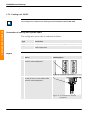
Installation and set-up
Wire feed system type A314E/316E/324E
1.5.3 Wire feed system type A314E/316E/324E
Action
Info/Illustration
1. Signal cable, FEED 2 (1)
• Prepare cable entry in the panel on
the process control equipment.
1
2. Motor cable, FEED 1 (2)
2
Installation and operation
• Prepare cable entry in the panel on
the process control equipment.
Figure 8 Panel for cable entry
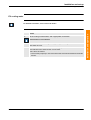
3. Signal cable, FEED 2
Connect wire feed unit (signal) to outlet
TB6 on PIB.
Signal cable with 23-pole connector at
robot base.
4. Motor cable, FEED 1
Connect wire feed unit (motor) to outlet
TB5 on PIB.
Motor cable with 12-pole connector at
robot base.
3HEA 802 347-002, Rev.- 2006-03
3
4
Figure 9 Connections on PIB
2-9
Installation and set-up
Connection of welding power source
1.6 Connection of welding power source
1.6.1 Welding power source, MigRob 500
See the separate manual under the tab “Power source” in the system manual for a
description of included welding power sources.
Installation and operation
Connection of welding power source, MigRob
Action
Info/Illustration
1. Cable to welding power source:
• Prepare cable entry in the panel on
the process control equipment:
1
Figure 10 Panel for cable entry
2. Connect the cable to outlet TB3 on PIB
in the process control equipment.
2
Figure 11 Connections on PIB
2-10
3HEA 802 347-002, Rev.- 2006-03
Installation and set-up
Welding power source, MigRob 500
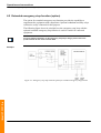
Connection of CAN bus/DeviceNet
Action
Info/Illustration
1. CAN drop out (1) to MigRob
2
• Prepare cable entry in the panel on
the process control equipment:
2. CAN IN (2) from SCC/DCC or safety
control equipment
• Prepare cable entry in the panel on
the process control equipment:
Installation and operation
1
3
3. CAN out (3)
• Prepare cable entry in the panel on
the process control equipment:
Figure 12 Panel for cable entry
4. The connection cable to PIB shall be
fitted with a termination resistor, 120Ω.
120Ù
I/O
I/O3.X5
I/O4.X5
I/O
I/O
I/O
A35.X2
A35.J1
OUT
A35.J1
IN
J1
I/O2.X5
A131.TB6
I/O1.X5
SIB
PCI
A35.X1
Block diagram
120Ù
Max length=6m
A35.J1
OUT
A35.J1
OUT
A35.J1
IN
MigRob
In
X7
Out
X4
PIB
A121.TB2
MigRob_1_Slide5.wmf
Trunk line
Drop line
Figure 13 CAN bus/DeviceNet for single arc with MigRob
3HEA 802 347-002, Rev.- 2006-03
2-11
Installation and set-up
Welding power source, RPB
1.6.2 Welding power source, RPB
See the separate manual in the section “Power source” for a description of included
welding power sources.
Connection of external welding power source
Installation and operation
Action
1. Cable for communications with PIB to
welding power source
Info/Illustration
1
• Prepare cable entry in the panel on
the process control equipment:
Figure 14 Panel for cable entry
2. Connect the cable to outlet TB3 on PIB
in the process control equipment.
2
Figure 15 Connections on PIB
2-12
3HEA 802 347-002, Rev.- 2006-03
Installation and set-up
Welding power source, RPB
Connection of CAN bus
Action
Info/Illustration
Installation and operation
1. Connection of the process control card is 1
made to the control system’s CAN bus
outlet A121.TB2.
Figure 16 PIB
2. The connection cable shall be fitted with
termination resistance, 120Ω
I/O
I/O2.X5
I/O
I/O3.X5
I/O4.X5
I/O
I/O
A35.X2
A35.J1
OUT
A35.J1
IN
J1
I/O1.X5
A131.TB6
PCI
120Ù
SIB
A35.X1
Block diagram
120Ù
A35.J1
OUT
A35.J1
IN
PIB
A121.TB2
RPB_1_Slide4.wmf
Trunk line
Drop line
Figure 17 CAN bus/DeviceNet for single arc with RPB
3HEA 802 347-002, Rev.- 2006-03
2-13
Installation and set-up
Accessory connections
1.7 Accessory connections
1.7.1 Welding torch
See separate manual, under the “Welding torch” tab, for description of the included
product.
Installation and operation
A cooling unit is required if a water-cooled welding torch is included
Connection of hose bundle
Cables and hoses in the hose bundle can be supplied connected according to the
following description. See Figure 20
Cable/hose
Type
Connection
Gas
Red hose
Connected to central gas supply or tank.
Cooling water
Blue hose (1)
Red hose (2)
IN
OUT
1
2
Figure 18 Wire feed unit
Air in
PVC hose D14/8 Connected to compressed air supply, system
pressure approx. 6 bar.
Wire guide input (1) For bobbin
For Marathon
Pac
Welding cable (2)
95 m2
1
2
Figure 19 Wire feed unit
Power cable
2-14
Connect to last power cable from wire feed unit to
welding power source.
3HEA 802 347-002, Rev.- 2006-03
Installation and set-up
Welding torch
1
8
2
6
5
4
3
j5000843
7
Figure 20 Connections on wire feed unit
Item
Designation
Item
Designation
1
Wire feed cable
5
Water hose IN (blue)
2
Wire feed cable 1
6
Air hose
3
Gas hose (red)
7
Welding cable
4
Water hose OUT (red)
8
Bolt
3HEA 802 347-002, Rev.- 2006-03
2-15
Installation and operation
Overview figure
Installation and set-up
Cooling unit, OCE 2
1.7.2 Cooling unit, OCE 2
The cooling unit is included in the welding torch kits PKI 500R and Binzel WH 455D.
Installation and operation
Connection of cooling unit's power cable
The cooling unit's power cable is connected as follows:
Type
Connection
RPB
The power cable is connected to the welding power source.
MigRob
The power cable is connected to terminal A12.K11 in the process
control equipment.
MigRob
Action
1. Prepare cable entry in the panel on the
process control equipment.
Info/Illustration
1
Figure 21 Panel for cable entry
2. Connect the cable from the cooling unit
to relay A12.K11 on the inside of the
process control equipment.
2
Figure 22 Connections in control
equipment
2-16
3HEA 802 347-002, Rev.- 2006-03
Installation and set-up
Cooling unit, OCE 2
Fill cooling water
Action
1.
Fill the cooling unit with water, and if appropriate, anti-freeze.
Distilled water is recommended.
2.
Check the flow in the welding torch by opening the cooling unit's return hose IN
until water runs out.
3.
If the water sensor is ordered afterwards, the jumper in the wire feed unit must be
removed before the water sensor can be used.
This is done as follows:
• Unscrew the jumper By1 on the terminal in the wire feed unit between terminals
2 and 4.
3HEA 802 347-002, Rev.- 2006-03
2-17
Installation and operation
For detailed information, see the manual for OCE 2.
Installation and set-up
Process options
1.7.3 Process options
Process options block diagram
1
3
2
4
Installation and operation
5
Figure 23 Process options block diagram
2-18
Pos. Description
Pos. Description
1
Welding torch
4
BullsEye, TCP calibration unit (process
option)
2
Wire cutter (process option)
5
Process control equipment
3
Spatter cleaning unit (process option)
3HEA 802 347-002, Rev.- 2006-03
Installation and set-up
Process options
Connection of spatter cleaning unit and BullsEye
1. Prepare cable entry in the panel on the
process control equipment:
Info/Illustration
1
Installation and operation
Action
Figure 24 Panel for cable entry
2. Connect the cable to output TB4 on PIB
in the control equipment for process
2
Figure 25 Connections on PIB
See the separate manual for mechanical spatter cleaning unit and BullsEye for a description
of component products.
3HEA 802 347-002, Rev.- 2006-03
2-19
Installation and set-up
Configuration of welding equipment
1.8 Configuration of welding equipment
1.8.1 General
Installation and operation
Upon delivery, the welding equipment is configured with the data that applies for
the pertinent equipment and this data is on the configuration floppy disk that
accompanies delivery.
The data can be read and modified from the robot's FlexPendant. For more
information, see “Configuration” on page 4 - 15.
1.8.2 Installation floppy disk
Store the floppy disk in a safe place; it may be unique for the delivered equipment.
The program number that is printed on the disk corresponds to the pertinent configuration
and shall be referenced in service matters that concern function of the welding equipment.
The following files on the installation disk contain configuration data for the
welding equipment:
File
RPB_FhpE.cfg
MigRob_FhpE.cfg
Configuration for:
• Welding power source RPB 320/420/520
• Wire feed unit A314E/316E/324E_PIB
• Welding power source, MigRob 500
• Wire feed unit A314E/316E/324E_PIB
1.8.3 Reload configuration data
In the event that configuration data must be reloaded, this can be conducted in
accordance with the following alternatives:
Alternative
Description
The robot is restarted
The original configuration is restored.
Input via the FlexPendant
In the event that a few parameters need to be modified
from the original configuration.
(EIO:CFG) With the robot instruction:
Loading of new
configuration file
System parameters\File\Add or change
parameters\ “file”.cfg.\.
“Loading of configuration file” on page 4 - 34
2-20
3HEA 802 347-002, Rev.- 2006-03
Installation and set-up
Brake hub (bobbin) adjustment
1.9 Brake hub (bobbin) adjustment
If the bobbin is used, it may be necessary to adjust the brake hub.
With high speeds and when the bobbin is new, the wire can roll off when the wire feed unit
stops. To prevent this, the brake hub's preset value of 5 kpcm (0.5 Nm) is adjusted.
Info/Illustration
Installation and operation
Action
1. Locate the brake hub (1).
1
2. Turn the knob (2) on the brake hub until
the arrows are aligned with one another
(locked bobbin position).
3. The springs (3) that are on each side of
the knob are turned inwards at the same
time to increase braking.
3
2
3
If the wire feed speed is so high that adjustment has no effect, the Marathon Pac should be
used.
3HEA 802 347-002, Rev.- 2006-03
2-21
Installation and set-up
Brake hub (bobbin) adjustment
Installation and operation
2-22
3HEA 802 347-002, Rev.- 2006-03
Operation
Inspection before start-up
2 Operation
2.1 Inspection before start-up
Installation and operation
!
All protection and all safety equipment must be installed before the station is put in service.
This should be especially noted in connection with maintenance and service.
Keep the door to the control equipment closed to prevent the entry of dust and dirt.
Inspection
Action
1.
Check that no tools have been forgotten.
2.
Check that the fixture and workpiece are well secured.
3.
Check that all parts and protections are in place and that they are well secured.
4.
Check that all functions are correct.
5.
Check that no emergency stop buttons are actuated.
6.
Check that:
• The right program has been loaded into the system.
• The cursor is at the instruction where the program is to start.
Do this in the teach pendant window; see the operator's manual for the robot.
3HEA 802 347-002, Rev.- 2006-03
2-23
Operation
Start-up
2.2 Start-up
All requisite system software is installed on delivery.
1.
Installation and operation
Action
Info/Illustration
Throw the main power switch on the
single/dual cabinet and the main
power switch on the welding power
source if fitted.
The main power switch on the single/
dual cabinet normally controls power
supply to all component units in the
cabinet.
Note:
Some welding power sources provide the process control card with external
reference voltage, which is why parts of the control cabinet can be energized even
when the main power switch is in the “OFF” position.
2-24
2.
The robot conducts a self-test of both
the hardware and software.
This test takes about one minute.
3.
Wait until the message
"Welcome to..."
appears on the teach pendant's
display.
The system is now ready for use.
3HEA 802 347-002, Rev.- 2006-03
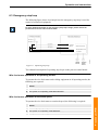
Operation
Wire feed
2.3 Wire feed
2.3.1 Operating mode
Operating mode selector
The operating mode selector has three positions:
Installation and operation
“Manual full speed 100%” is not included in certain deliveries, and the operating mode
selector then has just two positions.
Figure 26 Operating mode selector
Mode
Description
Auto
Manual reduced speed (<250 mm/s)
100%
Manual full speed (100%)
2.3.2 Wire feed motor operation in all operating modes
To operate the wire feed motor and welding equipment in all operating modes, the
following are required:
Action
1. All safety loops are intact
2. The system is in operating mode MOTORS ON
3HEA 802 347-002, Rev.- 2006-03
2-25
Operation
Manual wire feed
2.3.3 Manual wire feed
Wire feed motor operation at restricted speed
To operate the wire feed motor at restricted speed, the following is required:
Action
Installation and operation
1. The emergency stop loop is intact
2. The system is in operating mode MANUAL
3. The system is in operating mode MOTORS OFF
Methods
Manual wire feed can be conducted with three different methods:
Action
Info/Illustration
1. By pressing the non-locking pushbutton
for manual wire feed on the welding
torch or on the front of the wire feed unit.
1
Figure 27 Manual wire feed at the front of
the wire feed unit
2. By activating the function Manual wire
feed from the robot's FlexPendant in test
mode under: Program
window\Arcweld\Manual wirefeed.
3. By activating the robot output doFEED in
combination with setting of a speed
reference in aoFEED_REF under the I/O
window.
2-26
Figure 28 FlexPendant
3HEA 802 347-002, Rev.- 2006-03
Diagnostics, fault handling
LEDs on PIB process unit
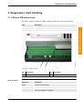
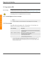
3 Diagnostics, fault handling
3.1 LEDs on PIB process unit
The PIB is equipped with two LEDs according to the DeviceNet specification.
Description
NS
(Network Status), indicates function of CAN bus
MS
(Module Status), indicates function of PIB
1
Lysdioder.jpg
Installation and operation
LED
2
Figure 29 LEDs on PIB
Pos. Description
Pos. Description
1
2
MS, Module Status
NS, Network Status
Fault indication
Indication
Description
Green
Indicates correct function
Red
Indicates incorrect function
Blinking green
During the initiation phase, which can take a few seconds, the LED
blinks until initiation is complete.
3HEA 802 347-002, Rev.- 2006-03
2-27
Diagnostics, fault handling
Upon fault in PIB
3.2 Upon fault in PIB
Error message
If a fault occurs in the PIB, an error message is displayed on the robot's FlexPendant
to indicate that corrective actions are necessary. See “Error message” on page 2 - 28.
The welding process is not stopped but actions are necessary.
Installation and operation
3.2.1 Acknowledgement of error messages
Action
1. Press the OK button on the FlexPendant to acknowledge an error message.
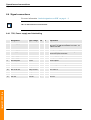
3.2.2 Error message
From PIBs with version numbers -503. -0702 and from -1100 and higher, the
number of error messages is limited to the following:
Error message
Description
80001 2 PIB error, warning Analog outputs outside limits
• Check the limits in ctrl.conf.part motor max/min Speed
and max Volt.
80001 4 PIB error, warning Digital Output overloaded in PIB, fatal error
• Check the output connections.
• Reset with power switch.1
80001 11 PIB error, warning source voltage 24 Volt on PIB too low
• Check incoming power source.
1. The overloaded (short-circuited) output is turned off by its overcurrent protection. The welding
process is only stopped if the process monitor is actuated. The function recovers after
switching on the power source to the PIB after the power source to the PIB is initially switched
off and the overload removed.
2-28
3HEA 802 347-002, Rev.- 2006-03
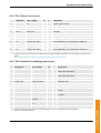
Diagnostics, fault handling
Collision sensors
3.3 Collision sensors
General
The PIB is designed for use by a welding torch equipped with a collision sensor.
During program execution, an error message is displayed that expressly states that
the collision sensor has been activated.
Message
Description
Message 1:
PIB error, warning
Welding torch has collided. If torch still in collision state, reset
from wire feed.
• Move robot with joystick; program may not be restarted.
Message 1 is displayed with G-stop (general stop) when a
welding torch remains out of position.
Message 2:
PIB error, warning
Weld torch has been reset.
Message 3:
PIB information
Torch has returned to normal position.
Messages 2 and 3 in the specified order will be displayed after restarts. If the
collision is brief, so that the welding torch is only momentarily out of position and
springs back, message 1 will not be displayed. However, messages 2 and 3 will be
displayed.
3HEA 802 347-002, Rev.- 2006-03
2-29
Installation and operation
3.3.1 Error messages during program operation
Diagnostics, fault handling
Error messages during program operation
Installation and operation
2-30
3HEA 802 347-002, Rev.- 2006-03
Tab 3:
Maintenance
1 Maintenance
1
1.1 General
1
1.2 Wire feed unit
1
1.2.1 Regular checks
1.3 Control equipment for welding equipment
1.3.1 Regular checks
2 Repairs
2
3
3
5
2.1 General
5
2.2 Wire feed unit
6
6
2.3 Process control equipment
8
2.3.1 Process unit PIB
2.3.2 Transformer for PIB
2.3.3 Before putting in service
8
12
14
Maintenance
2.2.1 Drive motor replacement
3HEA 802 347-002, Rev.- 2006-03
Maintenance i
Maintenance
Maintenance ii
3HEA 802 347-002, Rev.- 2006-03
Maintenance
General
1 Maintenance
1.1 General
This work may only be carried out by persons trained in the use of the complete system and
who are aware of the special risks involved with the various parts.
!
Turn off the mains voltage and (if possible) lock the circuit breaker before starting work on the
equipment.
In some cases however, work must be done with the mains voltage switched on; special care
and safe working methods must then be exercised.
NOTE: Use only extra equipment and original spare parts recommended by ABB.
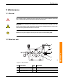
1.2 Wire feed unit
2
1
5
1
3
j5000841
6
Figure 1 Wire feed unit
Item
Description
Item
Description
1
Upper feed roller
4
Motor
2
Set screw
5
Inlet nozzle
3
Lower feed roller
6
Screw
3HEA 802 347-002, Rev.- 2006-03
3-1
Maintenance
4
Maintenance
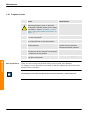
Regular checks
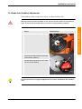
1.2.1 Regular checks
Action
1.
!
2.
Info/Illustration
DANGER:
Before beginning any work on the IRC5
control/drive modules, please see the safety
information in section “DANGER – Ensure
that the main power switch is turned off.” on
page 1 - 5
Perform a visual inspection of the equipment.
• Correct any faults.
3.
As necessary, clean the wire feed unit with
dry compressed air at reduced pressure.
4.
Clean the recesses on the feed rollers and
nozzle openings.
5.
Clean the wire guide with compressed air
each time the wire is changed or as required.
To ensure good wire feed, the
recesses on the feed rollers
should be periodically cleaned.
• Replace worn wire guides
6.
Maintenance
Wire replacement
Using welding wire that is as clean and free
from grime as possible
Grime can cause slippage.
There are two recesses on the feed rollers, one for each wire diameter.
To change recesses, the rollers are turned so that the marking for the desired wire
diameter faces outwards.
The bearings for the motor and gearing do not require lubrication – maintenance-free
3-2
3HEA 802 347-002, Rev.- 2006-03
Maintenance
Control equipment for welding equipment
1.3 Control equipment for welding equipment
General
!
Certain routine checks and preventive maintenance tasks must be performed at
certain specified intervals.
DANGER:
Before beginning any work on the IRC5 control/drive modules, please observe the safety
information in the section "Warning – Ensure that the main switch is turned off" on page 5.
WARNING!
The unit is sensitive to ESD; before beginning any task involving the unit, please see the
safety information in section
"WARNING – The unit is sensitive to ESD" on page 6.
1.3.1 Regular checks
Action
Info/Illustration
1. The control system is fully enclosed, and
the electronics are thereby protected in a
normal workshop environment.
In environments with significant levels of
dust and airborne particles, the inside of
the cabinet should be regularly
inspected.
• If necessary, use a vacuum cleaner.
• Clean filters, if fitted.
Maintenance
2. Check that the sealing strips and cable
entries are properly sealed so that dirt is
not drawn into the process control
equipment.
• If necessary, use a vacuum cleaner.
3. Check that the cables/connectors are
not damaged.
• Damaged components must be
replaced immediately.
3HEA 802 347-002, Rev.- 2006-03
3-3
Maintenance
Regular checks
Maintenance
3-4
3HEA 802 347-002, Rev.- 2006-03
Repairs
General
2 Repairs
2.1 General
Certain routine checks and preventive maintenance tasks must be performed at
certain specified intervals.
This work may only be carried out by persons trained in the use of the complete system and
who are aware of the special risks involved with the various parts.
!
Turn off the mains voltage and (if possible) lock the circuit breaker before starting work on the
equipment.
In some cases however, work must be done with the mains voltage switched on; special care
and safe working methods must then be exercised.
Maintenance
NOTE: Use only extra equipment and original spare parts recommended by ABB.
3HEA 802 347-002, Rev.- 2006-03
3-5
Repairs
Wire feed unit
2.2 Wire feed unit
2.2.1 Drive motor replacement
2
4
1
5
1
3
j5000841
6
Figure 2 Wire feed unit
Maintenance
Item
Description
Item
Description
1
Upper feed roller
4
Motor
2
Set screw
5
Inlet nozzle
3
Lower feed roller
6
Screw
Dismantling
Action
1.
!
3-6
DANGER:
Before beginning any work on the IRC5 control/drive modules, please see the
safety information in section “DANGER – Ensure that the main power switch is
turned off.” on page 1 - 5
2.
Remove both feed rollers.
3.
Remove the drive wheel and the three socket head cap screws.
4.
Lift out the motor.
3HEA 802 347-002, Rev.- 2006-03
Repairs
Drive motor replacement
Installation
Upon replacement or repair of a drive motor, the drive motor shaft during re-installation must
be centered in relation to both feed rollers with a centering unit, so as to avoid gear tooth and
bearing wear.
Action
1. Fit the new motor.
2. Center the motor's drive shaft in relation to both feed rollers using the centering unit.
3. Fit the drive wheel and the three socket head cap screws.
4. Fit both drive rollers.
Centering unit
Order number
Centering unit
500 332-001
Maintenance
Designation
3HEA 802 347-002, Rev.- 2006-03
3-7
Repairs
Process control equipment
2.3 Process control equipment
2.3.1 Process unit PIB
Location
The PIB is located in the process control equipment according to Figure 3.
Location
Maintenance
3HEA802174-001.wmf
1
Figure 3 Process control equipment
3-8
Pos. Description
Designation
1
A121
Process unit PIB
3HEA 802 347-002, Rev.- 2006-03
Repairs
Process unit PIB
Dismantling
Step
1.
!
2.
Illustration
DANGER:
Before beginning any work on the IRC5
control/drive modules, please see the
safety information in section “DANGER
– Ensure that the main power switch is
turned off.” on page 1 - 5
WARNING!
The unit is sensitive to ESD; before
beginning any task involving the unit, please
see the safety information in section
“WARNING – The unit is sensitive to
ESD.” on page 1 - 7
3.
Open the process control equipment.
4.
Disconnect all cables from the PIB.
4
Figure 4 PIB
6.
Remove the locking fixture with a
screwdriver.
5
Maintenance
5.
Tip the PB unit away from the installation
bar and remove it.
6
Figure 5 Locking fixture
Adaptation of process unit PIB to control system IRC5
General
The PIB contains two program versions. The correct program version is dependent
on the control system used. Which program version is active is determined by
jumper TB9.
3HEA 802 347-002, Rev.- 2006-03
3-9
Repairs
Process unit PIB
Upon delivery
All PIBs delivered as spare parts or components are preconfigured for ARCITEC/LRA and
wire feed unit A314 upon delivery. This means that jumper TB9 is closed.
IRC5
Action
Info/Illustration
1. Remove the jumper TB9
Upon change of
PIB
Maintenance
Previously stored configuration parameters in the robot are automatically
transferred at power-up to the new PIB board.
Configuration data for ABB's standard equipment is included on the configuration
floppy disks for the AW system.
“Configuration parameters” on page 4 - 29, where all parameters are listed and
defined.
When changing a PIB, the unit must be restarted twice.
3-10
3HEA 802 347-002, Rev.- 2006-03
Repairs
Process unit PIB
Installation
Step
1.
!
2.
Illustration
DANGER:
Before beginning any work on the
IRC5 control/drive modules, please
see the safety information in section
“DANGER – Ensure that the main
power switch is turned off.” on page
1-5
WARNING!
The unit is sensitive to ESD; before
beginning any task involving the unit,
please see the safety information in
section
“WARNING – The unit is sensitive to
ESD.” on page 1 - 7
3.
Open the process control equipment.
4.
Place the PIB unit on the installation
bar and clamp it in place.
4
5.
Connect the cables on the PIB unit.
6.
Shielding connection of cables
Maintenance
Figure 6 Process unit in process control
equipment
• Tighten the clamps with firm
pressure against the metal bar.
The metal bar on the top of the PIB has
holes for installation of two shield
clamps that accompany the PIB upon
delivery.
Figure 7 Cable shielding
It is important for the function of the PIB that the shielding connection is made with
the greatest possible care. This primarily applies to the two cables from the wire feed
unit. If possible, they should be run so that there is space between them.
7.
Open the process control equipment.
3HEA 802 347-002, Rev.- 2006-03
3-11
Repairs
Transformer for PIB
2.3.2 Transformer for PIB
Location
The transformer for the PIB is located in the process control equipment according
to Figure 8.
Maintenance
3HEA802174-001.wmf
1
Figure 8 Transformer for PIB in process control equipment
3-12
Item
Description
Item
designation
1
Transformer for PIB (42 VAC)
T12
3HEA 802 347-002, Rev.- 2006-03
Repairs
Transformer for PIB
Dismantling
Step
1.
!
Illustration
DANGER:
Before beginning any work on the IRC5
control/drive modules, please see the
safety information in section “DANGER
– Ensure that the main power switch is
turned off.” on page 1 - 5
2.
Open the door to the process control
equipment.
3.
Disconnect the cable to the transformer
4.
Remove the retaining screws.
3
5.
Remove the transformer.
5
4
Maintenance
Figure 9 Safety equipment with
transformer
3HEA 802 347-002, Rev.- 2006-03
3-13
Repairs
Before putting in service
Installation
Step
1.
!
Illustration
DANGER:
Before beginning any work on the
IRC5 control/drive modules, please
see the safety information in section
“DANGER – Ensure that the main
power switch is turned off.” on page
1-5
2.
Open process control equipment
3.
Position the transformer.
4.
Fit the retaining screws.
5
5.
Connect cabling to terminal in
accordance with diagram.
3
4
2
Maintenance
Figure 10 Safety equipment with
transformer
6.
Close process control equipment.
2.3.3 Before putting in service
!
Inspection
All protection and all safety equipment must be in place before the station is put in service.
This should be especially noted in connection with maintenance and service.
Before commissioning, the following should be checked:
Action
3-14
1
Check that no tools have been forgotten.
2
Check that the fixture and workpiece are well secured.
3
Check that all parts and protections are in place and that they are well secured.
4
Check that all functions are correct.
3HEA 802 347-002, Rev.- 2006-03
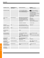
Process unit PIB
1 Process control equipment
1
1.1 Process unit PIB
1
1.1.1 General
2 Technical specification
3
2.1 Mechanical data
3
2.2 Electrical data
3
2.3 Environmental data
4
3 Safety
5
3.1 Personal safety
3.1.1 Interlocking
3.1.2 Manual wire feed
3.2 Machine safety
3.2.1 Collision detection
3.2.2 Collision sensor (option)
3.3 Collision sensors
3.3.1
3.3.2
3.3.3
3.3.4
General
Upon activation of a collision sensor
Reset
During program execution
3.4 Electronics
5
5
5
6
6
6
7
7
7
7
8
9
3.5 Versions and options
10
3.5.1 Voltage versions
3.5.2 Transformer
10
11
3.6 Marking and version management
3.6.1 Hardware version
3.6.2 Program version
3.7 Options
3.7.1 Smartac
4 Configuration
13
13
13
14
14
15
4.1 General
15
4.2 Configuration parameters
15
4.2.1 Upon change of PIB
15
5 Installation
17
5.1 Adaptation of process unit PIB to control system IRC5
5.1.1 General
5.1.2 IRC5
5.1.3 Upon delivery
3HEA 802 347-002, Rev.- 2006-03
1
17
17
17
18
PIB i
Process unit PIB
Tab 4:
6 Operation and connections
19
6.1 Emergency stop
19
6.2 Extended emergency stop function (option)
20
6.3 Emergency stop loop
21
6.4 Signal connections
22
6.4.1
6.4.2
6.4.3
6.4.4
6.4.5
6.4.6
6.4.7
TB1, Power supply and interlocking
TB2, CAN bus connection
TB3 Connection to welding power source
TB4 Connection to torch cleaner and TCP detector
TB5 Connection 1 to wire feed unit
TB6 connection 2 to wire feed unit
TB11
22
23
23
24
24
25
25
6.5 Circuit diagram, wire feed unit A314E/316E/324E
26
6.6 Manual wire feed with PIB and IRC5
27
6.6.1 Capabilities and limitations
27
Process unit PIB
PIB ii
3HEA 802 347-002, Rev.- 2006-03
Process control equipment
Process unit PIB
1 Process control equipment
1.1 Process unit PIB
1.1.1 General
The PIB is an I/O unit with an integrated wire feed regulator that communicates
directly with ABB's IRC5 robot control system. It is used for control and monitoring
of robot welding.
Configuration is conducted in a manner corresponding to a standard I/O unit,
The PIB's properties are determined through transfer of configuration parameters
for power sources and wire feed units. Communications with the robot computer are
via serial communications on a CAN bus.
The I/O connections on the PIB are grouped, see Figure 2, for direct cable
connection.
Location
4
1
3
3HEA802174-001.wmf
2
Figure 1 Process control equipment
1
Transformer, see “Transformer” on page 4 - 11
2
Process unit PIB
3
Cable entry for process equipment, see“Cable entries on the control
equipment for process equipment” on page 1 - 19
4
Interlock unit and jackable terminals for process equipment, see
“Connections in control equipment for process equipment” on page
2-7
3HEA 802 347-002, Rev.- 2006-03
Designation
A121
4-1
Process unit PIB
Pos. Description
Process control equipment
General
Process unit PIB
7
6
5
4
3
2
1
0
8 9
10
PIB.wmf
1
11
Figure 2 Outlet designations on PIB
Item
Description
Item
designation
1
Outlet for power supply and interlocking
A121.TB1
2
Outlet for CAN bus/DeviceNet
A121.TB2
3
Outlet for welding torch accessories
A121.TB4
4
Outlet for wire feed unit (signal)
A121.TB6
5
Outlet for wire feed unit (motor)
A121.TB5
6
Outlet for welding power source
A121.TB3
7
Outlet
A121.TB11
8
Outlet for program loading
9
Jumper
10
Switch for program loading
11
Euro connector add-on board for joint tracking
A121.TB9
Process unit PIB
4-2
3HEA 802 347-002, Rev.- 2006-03
Technical specification
Mechanical data
2 Technical specification
2.1 Mechanical data
Type
Data
Dimensions:
257x196x72.5 mm
Weight:
2.1 kg
Enclosure class:
IP 20
2.2 Electrical data
Type
Description
Data
Power supply:
“Transformer” on page 4 - 12 -Transformer
Digital outputs
Continual load/output:
Max. 350 mA
Total load, outputs:
Max. 1.6 A, < 70°C
Actuation of overload protection per output:
370 mA
Notes: At a capacitive load of > 0.05 uF, a
momentary overload may occur that actuates the
overload protection when connecting power. If
this occurs, a current limiting resistor must be
wired in series with the connected load.
Digital inputs,
24V DC:
Input voltage, connection:
15 to 35V
Input voltage, disconnection:
-35 to +5V
Input impedance
4 kohm, resistive
42V AC outputs:
Max. current:
1A at < 70°C
Relay outputs:
Max. voltage:
250V AC
Max. current:
10 A
Notes: Contact protestation must be connected
externally
3HEA 802 347-002, Rev.- 2006-03
Output voltage range:
0 - 15 V, < = 100 mA,
< = 70°C.
4-3
Process unit PIB
Analog outputs:
Technical specification
Environmental data
2.3 Environmental data
Temperature data:
At standstill
During
operation
In compliance
with:
Cold:
-40ºC, 16 hrs.
+5ºC, 2 hrs.
IEC 68-2-1
Heat:
+70ºC, 16 hrs.
+70ºC, 2 hrs.
IEC 68-2-2
Change:
-40ºC/+ 70ºC
2 cycles
IEC 68-2-14
Vibration:
EC 68-2-6
EMC: (Electro Magnetic
Compatibility)
EN 50199
LVD: (Low Voltage Directive)
EN 60204
Process unit PIB
4-4
3HEA 802 347-002, Rev.- 2006-03
Safety
Personal safety
3 Safety
3.1 Personal safety
Moving functions that are stipulated by the EU's machine directory as able to cause
personal injury, are interlocked via the robot's continuous pressure device and
emergency stop circuitry.
Such functions are:
• Manual wire feed
• Torch cleaning
3.1.1 Interlocking
Where national legislation requires that welding power sources also be interlocked,
the interlocking system can be complemented with a relay that opens the welding
power source control circuit.
3.1.2 Manual wire feed
For manual wire feed that is conducted from the welding torch or wire feed unit's
pushbutton, wire can be fed without actuation of the continuous pressure device for
a maximum of 6 m/minute.
The longer the button is held down, the higher the speed.
3HEA 802 347-002, Rev.- 2006-03
4-5
Process unit PIB
Manual wire feed: See “Manual wire feed with PIB and IRC5” on page 4 - 27
Safety
Machine safety
3.2 Machine safety
3.2.1 Collision detection
The robot function for collision detection is defined as standard for A314E/316E/
324E systems.
Important:
The mechanical collision sensor function in the PIB must be deactivated through a
connection of +24V to PIB input TB 6.2.
The absence of this signal will otherwise by interpreted by the PIB as a collision and the
wire feed unit will be blocked.
Jumper By2 in the wire feed unit is already prepared for this and at delivery is wired in the
closed position when no collision sensor is installed. See note 2. “Circuit diagram, wire feed
unit A314E/316E/324E” on page 4 - 26
3.2.2 Collision sensor (option)
The mechanical collision sensor is ordered as an option
Important:
Jumper By2 must be in the open position when collision sensor is installed.
See note 2. “Circuit diagram, wire feed unit A314E/316E/324E” on page 4 - 26
The following description “Collision sensors” on page 4 - 7 applies when a collision
sensor is installed.
Process unit PIB
4-6
3HEA 802 347-002, Rev.- 2006-03
Safety
Collision sensors
3.3 Collision sensors
3.3.1 General
The PIB is designed for use by a welding torch equipped with a collision sensor.
Normally, the sensor shall provide 24V DC to the PIB's input TB6.2.
The collision sensor controls the "run chain" relay in the PIB. The relay has two
poles and is included in the robot's G-stop chain (general stop). Normally, the relay
is activated.
3.3.2 Upon activation of a collision sensor
When a collision sensor is activated, the run chain relay is deactivated and the Gstop loop opens, which entails a rapid stop caused by the robot leaving the operating
mode and entering the standby mode. The message G-stop (general stop) is
displayed on the robot's FlexPendant. The message remains until it is acknowledged
with the OK button.
Return to service
after collision
For the robot to be put in service again, the G-stop chain must first be re-closed.
If the torch has been temporarily out of position but springs back, the G-stop chain
is closed and the robot can be returned to service.
If the torch remains in the wrong position, for example, when a collision state with
a weld object, fixture, etc., remains, the robot must be moved so that the torch
springs back. On ABB's wire feed unit A-314, there is a spring-back pushbutton
(reset) on the front of the wire feed unit for this purpose.
Return to service
after collision
Upon reset of the collision sensor, the microprocessor in the PIB activates the run
chain relay and closes the G-stop chain. The robot can be returned to service, and
with the robot's joystick, the robot can be moved so that the torch springs back and
resets the collision sensor in the closed position. The reset function is then
automatically acknowledged.
Program start
Program execution start is blocked until acknowledgement is made. Attempts to
start the program prior to acknowledgement cause the run chain relay to deactivate
and the G-stop chain to open again, necessitating a repeat of the reset procedure.
Reset limitation
To prevent the PIB (for example, because of an open circuit) from remaining at the
reset function and a new collision not being able to stop the robot, the time for reset
is limited to 1 minute. Thereafter, the G-stop (general stop) chain is opened again
and the reset procedure must be repeated.
The above applies both to manual control of the robot and program execution.
3HEA 802 347-002, Rev.- 2006-03
4-7
Process unit PIB
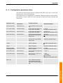
3.3.3 Reset
Safety
During program execution
3.3.4 During program execution
During program execution, an error message is displayed that expressly states that
the collision sensor has been activated.
Error messages
Message
Description
Message 1:
PIB error, warning
Welding torch has collided. If torch still in collision state, reset
from wire feed.
• Move robot with joystick; program may not be restarted.
Message 1 is displayed with G-stop (general stop) when a
welding torch remains out of position.
Message 2:
PIB error, warning
Weld torch has been reset.
Message 3:
PIB information
Torch has returned to normal position.
Messages 2 and 3 in the specified order will be displayed after restart. If the collision
is brief, so that the welding torch is only momentarily out of position and springs
back, message 1 will not be displayed. However, messages 2 and 3 will be
displayed.
Process unit PIB
4-8
3HEA 802 347-002, Rev.- 2006-03
Safety
Electronics
Design
The PIB is designed to withstand short-circuiting of outputs and overloading of the
motor regulator.
Overloaded outputs are deactivated. The function recovers after switching on the
power after the power supply to the PIB is switched off and the overload removed.
Motor regulator
The motor regulator is protected by current limiting in the final stage.
Other units
Other units connected to the PIB are also protected through maximum and minimum
data being configured, such as maximum reference for a welding power source,
maximum speed for the connected wire feed unit.
Error message
As described in chapter “Diagnostics, fault handling” on page 2 - 27, an error
message is generated to indicate a proposed action. The welding process is not
stopped.
3HEA 802 347-002, Rev.- 2006-03
4-9
Process unit PIB
3.4 Electronics
Safety
Versions and options
3.5 Versions and options
3.5.1 Voltage versions
The PIB is available in two voltage versions; see the table below and “Marking and
version management.” on page 4 - 13 for additional information.
Voltage version
Description
Part number
005-Low voltage
Wire feed unit with power supply to the wire feed
unit regulator's final stage at max. 42V AC/10A.
501 700-880
006-High voltage
Wire feed unit with power supply to the wire feed 501 700-881
unit regulator's final stage at max. 115V AC/3.5A.
A connection of 115V AC to the low voltage version of the PIB results in destruction of the
circuit board.
High voltage version:
A protective ground cable (min. 2.5 mm2) shall be connected, prior to turning on the power,
between the PIB's holed metal bar and the control equipment's protective ground bar.
Process unit PIB
4-10
3HEA 802 347-002, Rev.- 2006-03
Safety
Transformer
3.5.2 Transformer
The transformer supplies the motor regulator part on the process control board with
42V (28V) AC and the rectifier part on the process control board with 28V AC.
The transformer is located in the rear section of the process control equipment.
Location
3HEA802174-001.wmf
1
Figure 3 Transformer for PIB in process control equipment
Item
Description
Item
designation
1
Transformer for PIB (42 VAC)
T12
SCC (single cabinet)
220 V from terminals X16.1 andX16.2 in SCC.
DCC (dual cabinet)
220 V from fuse F2/2 and K 41 in drive module for DCC.
3HEA 802 347-002, Rev.- 2006-03
4-11
Process unit PIB
220 V supply to process control equipment
Safety
Transformer
Versions
.
Version
Part number
Low voltage (LV)
501 714-001
High voltage (HV)
501 714-002
brown
yellow
black
28V 7.5A
Uo=28.9V
red
42V 7.5A
Uo=43.5V
0-115V
0-28V
0-28V 0-28-42V
S1
white
S2
28V 3A
Uo=28.9V
white
115V 2.7A
Uo=118.9V
orange
230V
50Hz
white
yellow
orange
yellow
white
28V 3A
Uo=28.9V
501714c1
P1
HV
-002
R=2.2 Ohm 10W
R=2.2 Ohm 10W
230V
50Hz
LV
-001
High Voltage
Low Voltage
yellow
0-230V
0-230V
Marking
Process unit PIB
Figure 4 Transformer
4-12
3HEA 802 347-002, Rev.- 2006-03
Safety
Marking and version management
3.6 Marking and version management
3.6.1 Hardware version
Location and disposition of article number and serial number. This marking shows
the PIB's hardware version, not the program version.
Extra marking
High voltage
Low voltage
Product for ABB
High voltage 006
Low voltage 005
Version number
ABB Welding
501 700-881
5601 006-1900
DAT: 2003-08-26
SNR: 1836280
Märkning.jpg
Part number
501 700-880, Low voltage
501 700-881, High voltage
Test date
Serial number
Figure 5 Marking and version management.
3.6.2 Program version
3HEA 802 347-002, Rev.- 2006-03
4-13
Process unit PIB
The program version is shown under the menu for configuration in the robot's
FlexPendant, and is a non-editable four-digit number. It is updated automatically
upon change of program version.
Safety
Options
3.7 Options
3.7.1 Smartac
smartac på PIB.jpg
The PIB is equipped for connection of an optional board that provides increased
functionality. This is connected in the 32-pole Euro unit.
smartac.jpg
Figure 6 Smartac fitted on PIB
Figure 7 Smartac
Process unit PIB
4-14
3HEA 802 347-002, Rev.- 2006-03
Configuration
General
4 Configuration
4.1 General
Through programmable parameters, adaptations can be made to different types of
welding equipment.
Configuration parameters determine:
• Regulation properties
• Scaling factors
• Offset values
• Maximum and minimum values, etc.
4.2 Configuration parameters
The configuration parameters are listed and their values can be edited on the robot's
FlexPendant under the menu:
Misc\System\Parameters\IO signals\Types?Units\PIB-name
(configured IO name)
Change values are automatically transferred to the PIB when the robot is started.
4.2.1 Upon change of PIB
Configuration of previously stored configuration parameters in the robot are
automatically transferred at power-up to the new PIB board (for exceptions, see
chapter “Adaptation of process unit PIB to control system IRC5” on page 4 - 17).
Configuration data for ABB's standard equipment is included on the configuration
floppy disks for the AW system.
See “Configuration parameters” on page 4 - 29, where all parameters are listed and
defined.
3HEA 802 347-002, Rev.- 2006-03
4-15
Process unit PIB
When changing a PIB, the unit must be restarted twice.
Configuration
Upon change of PIB
Process unit PIB
4-16
3HEA 802 347-002, Rev.- 2006-03
Installation
Adaptation of process unit PIB to control system IRC5
5 Installation
5.1 Adaptation of process unit PIB to control system IRC5
5.1.1 General
The PIB contains two program versions. This is because different program versions
are needed, depending on which control system is used. The active program version
determined by jumper TB9.
5.1.2 IRC5
For IRC5 robot systems, jumper TB9 must be open (removed or secured to a single
pin).
With the jumper in this position, the following are supported:
• Transfer of configuration data from the robot's FlexPendant.
Bygling_TB9_överblick.jpg
• Automatic transfer of configuration data from the robot upon replacement of a
PIB.
See description in “Configuration parameters” on page 4 - 15.
3HEA 802 347-002, Rev.- 2006-03
4-17
Process unit PIB
Figure 8 PIB, jumper TB9.
Installation
Upon delivery
5.1.3 Upon delivery
All PIBs delivered as spare parts or components are preconfigured for ARCITEC/LRA and
wire feed unit A314 upon delivery. This means that jumper TB9 is closed.
Type of delivery
Description
Complete system
Upon delivery of a complete system, TB9's position is
predetermined.
Spare part or component
For use with an IRC5, the jumper must be removed and the
parameter transfer can be conducted as described in chapter.
Process unit PIB
4-18
3HEA 802 347-002, Rev.- 2006-03
Operation and connections
Emergency stop
6 Operation and connections
6.1 Emergency stop
All emergency stop buttons in the system are connected in series by default and
directly affect the control system's emergency stop loop.
On welding equipment belonging to the standard assortment, emergency buttons are
included on:
• Single cabinet/dual cabinet/external operator panel IRC5
Emergency stop on welding power source
If the process equipment is fitted with emergency stop buttons, they can be
connected in series with other buttons in the system.
The equipment is normally interlocked via the emergency stop relay on the control
system’s panel board A81.
Example
The following figure shows in principle how the emergency stop loop is used for
control of connected equipment.
For more detailed information on the emergency stop loop's design, please refer to the
product manual for the robot controller IRC5.
3HEA 802 347-002, Rev.- 2006-03
4-19
Process unit PIB
Figure 9 Emergency stop loop
Operation and connections
Extended emergency stop function (option)
6.2 Extended emergency stop function (option)
The option for extended emergency stop function provides the capability to
supplement the equipment with components. Optional redundant auxiliary relays
can then be easily connected for this purpose.
The following figure shows in principle how the emergency stop loop with the
optional extended emergency stop function is used for control of connected
equipment.
For more detailed information on the emergency stop loop's design, please refer to the
product manual for the robot controller IRC5.
Example
Figure 10 Emergency stop loop with the option for extended emergency stop function
Process unit PIB
4-20
3HEA 802 347-002, Rev.- 2006-03
Operation and connections
Emergency stop loop
6.3 Emergency stop loop
The following figure shows in principle how the emergency stop loop is used for
control of connected equipment,
For more detailed information on the emergency stop loop's design, please refer to the
product manual for the robot controller IRC5.
24 V
VOLTAGE
SUPPLY
run chain
0V
Figure 11 Operating stop loop
Two-channel interruption of operating stop loops on the process control board.
Wire feed motor operation in all operating modes
To operate the wire feed motor and welding equipment in all operating modes, the
following are required:
Action
1. All safety loops are intact
2. The system is in operating mode MOTORS ON
Wire feed motor operation at restricted speed
To operate the wire feed motor at restricted speed, the following is required:
1. The emergency stop loop is intact
2. The system is in operating mode MANUAL
3. The system is in operating mode MOTORS OFF
3HEA 802 347-002, Rev.- 2006-03
4-21
Process unit PIB
Action
Operation and connections
Signal connections
6.4 Signal connections
For more information “Outlet designations on PIB” on page 4 - 2.
TB is an abbreviation for Terminal Block
6.4.1 TB1, Power supply and interlocking
Designation
Type, voltage
Out
In
1
Motor supply
AC
Power supply to motor regulator, interlocked
42V max., for PIB 501700-880 115V max., for
PIB 501700-881
2
Motor supply common
AC
Zero power supply
3
Ext. supply
AC
Power supply non-interlocked for magnetic
valves and push feed units
4
Logic supply
28V AC
Power supply for logic circuits
5
Logic supply common
0V AC
Zero power supply for logic circuits
6
Ground plane
0V DC
Ground plane
7
I/O 24, VS
DC
8
Manual wire feed out
24V DC
9
Run chain A1
Relay contact
Run chain A
10
Run chain A2
Relay contact
Run chain A
11
Run chain B1
Relay contact
Run chain B
12
Run chain B2
Relay contact
Run chain B
13
24V ext
24V DC
x
x
x
Explanation
Non-interlocked 24V DC
Control signal for closing of interlock contactor
24V DC
Process unit PIB
4-22
3HEA 802 347-002, Rev.- 2006-03
Operation and connections
TB2, CAN bus connection
6.4.2 TB2, CAN bus connection
Designation
Type, voltage
Out
In
1
V-
DC
System 0 (from robot)
2
CAN_L
Serial com.
CAN low 1
3
DRAIN
DC
Ground, shield
4
CAN -H
Serial com.
CAN high 1
5
V+
DC
6
GND
DC
0 V for addressing
7
NA 0
Jumper, NC: active
Binary addressing, not connected to TB2:6=1
8
NA 1
Jumper, NC: active
Binary addressing, not connected to TB2:6=2
9
NA 2
Jumper, NC: active
Binary addressing, not connected to TB2:6=4
10
NA 3
Jumper, NC: active
Binary addressing, not connected to TB2:6=8
11
NA 4
Jumper, NC: active
Binary addressing, not connected to TB2:6=16
12
NA 5
Jumper, NC: active
Binary addressing, not connected to TB2:6=32
x
Explanation
System 24 V (from robot)
1. Termination resistance of 120 ohms is installed between TB2/2 and TB2/4 if the PIB is the outer (distance) I/O unit in the
system.
See recommendations for connection of termination in the robot's product manual.
6.4.3 TB3 Connection to welding power source
Type, voltage
Out
In
Explanation
1
Start power source A Closing contact
x
Control relay for welding power source (or
cooling fan ARCITEC)
2
Start power source B Closing contact
x
Control relay for welding power source (or
cooling fan ARCITEC)
3
Weld ref.
Analog 0-15 V
x
Reference for welding voltage
4
PS Ref. gnd
Analog common
x
Reference zero
5
Induct. Ref
Analog 0-15 V
x
Reference for inductance setting
6
Weld object
Analog
7
Arc voltage gun
Analog
8
Arc voltage object
Analog
9
24V ext
Supply voltage
+24V DC
x
For external relay
10
Ground plane
Supply voltage +0V x
DC
For external relay
11
NC
x
x
Detection of welding voltage on welding object1
Return of welding power to welding power
source
Detection of welding voltage on welding object
for PDM.2
Not connected
1. Common connection to welding object and welding power source, and negative pole for Smartac/PIB.
2. PDM: Process Data Monitoring
3HEA 802 347-002, Rev.- 2006-03
4-23
Process unit PIB
Designation
Operation and connections
TB4 Connection to torch cleaner and TCP detector
6.4.4 TB4 Connection to torch cleaner and TCP detector
Designation
Type, voltage
Out
In
Explanation
1
24V ext
Supply 24V DC
x
2
Ground plane
Supply zero
0V DC
x
3
Lubrication
Digital 24V DC
x
Lubrication for cleaning reamer
4
Cleaning
Digital 24V DC
x
Cleaning reamer
5
Wire cutter
Digital 24V DC
x
Wire cutter
6
Cleaning finished
Digital 24V DC
x
Cleaning finished
7
Bulls Eye
Digital 24V DC
x
Detection stop, TCP detector
In
Explanation
6.4.5 TB5 Connection 1 to wire feed unit
Designation
Type, voltage
Out
1
Motor +
0-60/0-170V DC
x
Motor voltage
2
Motor -
x
Motor voltage
3
Pneumatic spatter
cleaning
42V AC
x
To magnetic valve for pneumatic spatter
cleaning
4
Gas valve
42V AC
x
To magnetic valve for protective gas
5
Arc voltage gun
0-70V DC
6
Smartac 1
40V DC
x
Search voltage for Smartac sensor 1
7
Ext. Supply
Phase 28/42V AC
x
Supply voltage to push feed unit
8
Ext. Supply common
Zero 28/42V AC
x
Supply voltage to push feed unit
9
Smartac 2
40V DC
x
Search voltage for Smartac sensor 2 1
10
Spatter cleaning A
Closing contact
Alternative parallel function for TB5:3 2
11
Spatter cleaning B
Closing contact
Alternative parallel function for TB5:3 2
12
Gas valve A
Closing contact
Alternative parallel function for TB5:4 2
13
Gas valve B
Closing contact
Alternative parallel function for TB5:4 2
14
Tig mode
24V DC
x
Option
15
Feed reverse
24V DC
x
Control signal for motor reversing
16
HF ignition
24V DC
x
Option
x
Arc voltage return 2
1. When using Smartac sensor 2, TB5:5 and TB5:9 are jumpered; see Smartac manual.
2. Appropriate contact protection required
Process unit PIB
4-24
3HEA 802 347-002, Rev.- 2006-03
Operation and connections
TB6 connection 2 to wire feed unit
6.4.6 TB6 connection 2 to wire feed unit
Designation
Type, voltage
1
Torch reset
2
In
Explanation
24V DC
x
Reset of collision sensor
Torch collision
sensor
24V DC
x
Collision sensor
3
Current sensor
24V DC
x
Welding power sensor
4
Water flow sensor
24V DC
x
Water flow sensor
5
Gas flow sensor
24V DC
x
Gas flow sensor
6
0V
NC
7
Tach input
DC pulse
x
DC or AC tach/input for encoder tach
8
Man. Wire feed
24/DC
x
Manual wire feed
9
+24V
Supply voltage
x
Supply voltage
10
0V
Supply voltage
x
Supply voltage/common for encoder tach
11
Motor temp.
Analog
12
Auxiliary motor
24V DC
13
PDM tach +
AC/DC
x
Tachometer for process data monitoring
14
PDM tach -
AC/DC
x
Tachometer for process data monitoring
15
+5V encoder
tach1)
DC
Out
Jumper for TB 6/10
x
x
Temperature sensor in wire feed unit
Control signal for push feed unit
x
Supply voltage for encoder tach
1. PIB high voltage
6.4.7 TB11
Type, voltage
1
Weld current A
2
In
Explanation
Analog
x
Shut connection for PDM
Weld current A
Analog
x
Shut connection for PDM
3
HF ignition
24V DC
x
Indication, HF ignition option
4
Smartac sensor
detect.
24V DC
3HEA 802 347-002, Rev.- 2006-03
Out
x
Alternative to sensor detect. Via CAN bus
4-25
Process unit PIB
Designation
Operation and connections
Circuit diagram, wire feed unit A314E/316E/324E
6.5 Circuit diagram, wire feed unit A314E/316E/324E
504806c01
Process unit PIB
Figure 12 Circuit diagram, wire feed unit A314E/316E/324E
4-26
3HEA 802 347-002, Rev.- 2006-03
Operation and connections
Manual wire feed with PIB and IRC5
6.6 Manual wire feed with PIB and IRC5
6.6.1 Capabilities and limitations
Manual wire feed can be conducted with three different methods:
• By pressing the spring-back button for manual wire feed located on the welding
torch or on the front of the wire feed unit.
• By activating the function Manual wire feed from the robot's FlexPendant in
test mode under: Program window\Arcweld\Manual wire feed.
• By activating the robot output doFEED in combination with setting of a speed
reference in aoFEED_REF under the I/O window.
Methods
Properties and
differences
The table below shows properties and differences between the methods.
See note 3 below concerning limitation of functionality for method 3
Method Speed1
Ramping function
Continuous
pressure
Setting of reference
switch
pressed
1
Max. 6m/min
Yes
No
Automatic
2
Max. 9m/min
Yes
Yes
Automatic
3
Full speed range No
Yes
Manual
Limited validity2
3HEA 802 347-002, Rev.- 2006-03
4-27
Process unit PIB
1. If the speed range is limited by the configuration parameters MotorMaxSpeed or
MotorMinSpeed, the limitation is in effect.
For ARCITEC: If the speed range is limited by the configuration parameter
MotorMachineID, the limitation is in effect.
2. Note: The reference is valid only as long as aoFEED is not changed by any other function:
Methods 1 and 2 or execution of a program with another value. After use of method 1 or 2, the
reference is reset to zero.
Operation and connections
Capabilities and limitations
Explanation
The table below explains differences between the methods:
Method Explanation
1
Arc welding function for manual wire feed in the robot is called from the PIB.
The robot input diMAN_WF is activated.
The robot activates the input doFEED with a reference in aoFEED, which
increases as a function of time when the wire feed button is depressed.
The function is active as long as the button is depressed. The speed is limited
to max. 6 m/min by the PIB.1.
2
The arc welding function for manual wire feed is called from the robot's
FlexPendant. The robot input diMAN_WF is activated.
The robot activates the input doFEED with a reference in aoFEED, which
increases as a function of time when the manual wire feed button is depressed.
The function is active as long as the button is depressed.
3
The reference range is expressed as 0 - 0.5 m/s (0 - 30 m/min). The function is
active as long as doFEED is set to 1.
1. Limitation for reasons of personal safety.
Process unit PIB
4-28
3HEA 802 347-002, Rev.- 2006-03
Appendix
Appendix A:
A - 1: Configuration parameters
The configuration parameters are defined for three requirements:
1. They shall be whole numbers so as to facilitate handing in the PIB's
microprocessor.
2. The whole numbers shall be sufficiently large for the desired accuracy and
resolution to be obtained.
3. Programming from the robot shall be possible to express in actual quantities,
for example, 24.4 m/min for wire speed, 32.2 V for welding voltage, etc. A
multiplier with one or more factors is necessary in several cases:
In the column ”Parameter range/denomination” in “Configuration
parameters table” on page4 - 31 the setting range for the parameter is
indicated and a number that defines what the configuration value shall be
multiplied by to express the actual relationship.
Example:
If "MotorCurrentLim” is indicated as the value 80, the definition means
"Motor Current Limit {0 …100}0.1 A” that the maximum permitted current is 8 A.
If "ProcEquipRefConv” is indicated as the value 8260, the definition means
{1000 …30000}E-3 that the relationship output voltage/reference is 8.260, etc.
The conversion factor for feed units with AC tachometer:
The conversion factor is obtained from:
k0=g × n × 100/(π × D × 60) [Hz/m/min × 100],
where:
k0
is the conversion factor for tachometer type 0
g
is the gear's gear ratio
n
is total tachometer periods/motor revolutions
D
is the feed rollers' diameter in meters
100
is the multiple.
3HEA 802 347-002, Rev.- 2006-03
4-29
Appendix PIB
If k0 was >65535, Tachometer type 2 would be configured, and at the same time, the
conversion value shall be set to k2 = k0/2.
The maximum permitted tachometer frequency is 27000 Hz, which limits the
maximum theoretical wire feed speed to Vmax = (π × D × 60 × 27000/(g × n)
[m/min]
Appendix
Regulation parameters for wire feed unit
Regulation parameters are:
• Feed Forward factor
• Motor Regulator P-factor
• Motor Regulator I-factor
These parameters have been tested for the wire feed units delivered as standard and
adjustment should be avoided. Changes can result in incorrect speeds or instability.
Adjustment should only be conducted in consultation with service personnel from
ABB Automation Technologies AB.
Transfer of parameters between robot and PIB
The configuration parameters are sent from the robot's system parameter memory to
the PIB each time the system is powered up. If the parameters are the same as what
is already in the PIB, no new entries are made in the PIB.
It the parameters in the PIB differ from those that come from the robot (for example,
after changing the PIB) the deviating parameters are entered in the PIB, which
results in the new PIB obtaining the same configuration as the previous1.
For the new parameters to apply, the system must be restarted twice.
System definition
If the parameter ”System definition” is changed, which entails a change of the I/O
type for the PIB, the parameter transfer is made in two steps. Redefinition is first
conducted for the new I/O unit in the robot, which requires a restart.
At the next start, the transfer to the PIB is executed, and for the new parameter to
apply for the PIB, an additional restart of the robot is necessary. Consequently, in
this case, the robot must be restarted twice. For the second start, it is enough to
perform a "warm start" of the system.
Appendix PIB
1.
4-30
Note that jumper TB9 shall be open.
3HEA 802 347-002, Rev.- 2006-03
Appendix
A - 2: Configuration parameters table
The table lists all parameters that are defined for the PIB. They can be viewed and
edited from the robot's FlexPendant.
Not all parameters are implemented as standard. Parameters that are implemented
and must have correct values for correct function are indicated with an asterisk and
in bold font.
Parameter name
Parameter name in
FlexPendant
Software Revision
SoftwareRevison
Current software revision (read- only)
Motor Max Voltage
MotorMaxVoltage
Maximum allowed voltage for
the DC motor connected.
{0...110} V
60 (Used as standard value)
Motor Current Limit
MotorCurrentLim
Maximum allowed voltage for
the DC motor connected.
{0...100} 0.1 A
100 (Used as standard value)
*Motor Max Speed
MotorMaxSpeed
Maximum allowed setting for
motor speed in motor speed
quantity units
{0...500} 0.1
300 (Used as standard value)
*Motor Max Speed
MotorMinSpeed
Minimum allowed setting for
motor speed in motor speed
quantity units
{0...500} 0.1
5 (Used as standard value)
*Motor Regulator
P-factor
MotorRegPFactor
Proportional factor of the motor {0...100}%
18 (Used as standard value)
speed PI regulator.
*Motor Regulator
I-factor
MotorRegIFactor
Integrating factor of the motor
speed PI regulator.
*Motor Regulator
Feedforward factor
MotorFeedForward
Feedforward factor of the motor {0...100}%
10 (Used as standard value)
speed PI regulator.
Motor Temp Limit
MotorTempLimit
Maximum allowed temperature {0...255} °C
for the motor.
*Motor Brake Ratio
MotorBrakeRatio
Defines the duty cycle of the
brake transistor.
{0...255}
0 = No brake.
255 = Full brake
255 (Used as standard value)
Motor Control Error
Time Limit
MotorCtrlErrTimeLim
Defines the maximum allowed
time for difference between
motor speed set value and
actual value before setting the
alarm
{0...255} 1/10 s
Parameter
range/denomination
{0...100}%
25 (Used as standard value)
4-31
Appendix PIB
3HEA 802 347-002, Rev.- 2006-03
Parameter behavior
Appendix
Parameter name
Parameter name in
FlexPendant
Parameter
range/denomination
Parameter behavior
*Motor Tacho
Conversion Factor
MotorTachoConv
For AC: 100 Frequency in Hz
{0...65535}
20650 (Used as standard
for 1 motor speed quantity.
For DC: 10000 Frequency in Hz value)
AC (tacho type 0): 0.01 Hz/
for 1 motor speed quantity.
motor speed quantity
AC fast (tacho type 2): 0.02 Hz/
motor speed quantity
DC (tacho type 1): e-4 V/motor
speed quantity
*Motor Tacho
Type
MotorTachoType
Determines type of tachometer
connected and used by the
motor speed regulator of the
PIB. Valid types are AC tacho
and DC tacho
{0,1}
0 (AC tacho)
1 (DC tacho)
2 (Fast AC tacho
0 (Used as standard value)
Motor DC Offset
MotorTachoDCOffset
Motor speed offset for DC
tachometer connected
{-1000...1000} 0.01 m/min.
(Or r/min, l/min)
Appendix PIB
*Process Equipment ProcEquipRef
Reference
Conv
Convers., Flexible
Conversion factor between the {1000...30000}e-3 Process
process quantity in the set
quantity/Vref
value and the reference voltage
*Process Equipment ProcEquipRef
Reference Offset,
Offset
Flx.
Offset value for the process.
{0...1000} 0.1 V
Given in process quantity units.
*Process Equipment ProcEquipMaxRef
Max Reference
Voltage
Maximum allowed reference
voltage.
{0...1000} 0.1 V
Process Data
Monitoring Speed
Conversion Factor
PdmSpeedConv
For AC: 100 Frequency in Hz
for 1 motor speed quantity
motor speed.
For DC: 10000 Voltage in V for
1 motor speed quantity motor
speed
{0...65535}
AC: 0.01 Hz/motor speed
quantity
DC: e-4 V/motor speed quantity
Process Data
Monitoring
Tacho Type
PdmTachoType
Type of tachometer used for
true process quantity
measurement
{0,1}
0 (AC tacho)
Process Data
Monitoring
Tacho DC Offset
PdmTachoDCOffset
PDM DC tacho offset
{-1000...1000} 0.01 motor
speed quantity
Process Data
Monitoring Current
Shunt Conversion
PdmShuntConv
Scale factor for the shunt used {0...65535} e-5 mV/A
in PDM.
15000
Process Data
Monitoring
Shunt Offset
PdmShuntOffset
PDM Shunt offset
4-32
{-32000...32000} mA
3HEA 802 347-002, Rev.- 2006-03
Appendix
Parameter name in
FlexPendant
*Sensor Detection
SensorDetectionSens
Sensitivity, Smartac
Parameter behavior
Parameter
range/denomination
Defines the search voltage drop {0...255} 1/10 V
for detection of contact with
workpiece
*Sensor Search
Voltage Valid Limit,
Smartac
SensorSearchVoltValid- Defines the lowest allowed
Lim
search voltage for start of
search.
{0...40} V
*System Definition
SystemDefinition
Defines the PIB system
configuration
(0,1)
0 = (Flexible)
1 = Not in use (Arcitec S4CPlus)
2 = Integrated Power source
IRC5
*Machine
Identification code,
ARCITEC
MotorMachineID
The motor machine
identification for the wire feed
range of the current wire feed
motor. Only valid for Arcitec
system
{0..255}
According to wire feed motor
cable
Inductance
Reference
conversion
OptProcEquipRefConv
Conversion factor between the {1000...30000}e-3 Process
process quantity in the set
quantity/Vref
value and the reference voltage
Inductance
Reference Offset
OpProcEquipRefOffs
Offset value for the process.
{0...1000} 0.1 V
Given in process quantity units.
3HEA 802 347-002, Rev.- 2006-03
4-33
Appendix PIB
Parameter name
Appendix
A - 3: Loading of configuration file
#**************************************************************
#
#
(c) ABB Automation Technologies AB,
#
Arc Welding Products
#
#
File: ESABMig_FhpE.cfg
#
Description:
#
ArcWeld PIB EIO parameter configuration for PowerSource
#
ESABMig 400t/500t and WireFeeder A314E/A324E
#
with DC Pulsed Tachometer.
#
Speed range 0.5 to 30 m/min.
#
Created:
#
Written by:
#
Version 1.0
#
1.0 LOJ
#
Initial Release
#
#**************************************************************
Installation
If you have received a configuration file on a CD, in accordance with the example
above, you can install it as follows:
1. Copy the CFG file to a floppy disk, or use a PC/laptop and the Ethernet/Service
outlet; use the FTP program to move the file manually between the PC and the
robot memory.
This is done in the same way as in the file manager or in Windows Explorer.
2. With the System parameter window open on the FlexPendant, select:
File\Add or change parameters\
3. Select the CFG
file
from the floppy disk or the folder where it was moved to.
4. Restart.
For more information, see the User's Manual.
Appendix PIB
4-34
3HEA 802 347-002, Rev.- 2006-03
Appendix
Appendix B:
B - 1: System accuracy: Verification and adjustment options
Wire feed: Wire feed unit A314E/316E/324E
Inspection
The wire feed unit's accuracy should be checked by measuring the motor
tachometer's pulse frequency and not by measurement of the amount of fed wire and
measurement of time so as to avoid errors due to wire slippage and errors in starting
and stopping.
Correct speed requires that the friction in the wire feed system is sufficiently low, so
that the wire feed unit regulator does not reach the current limit (10A).
The frequency signal is available at the terminal TB6: 7 (5 V pulse) and 10 (0 V) at
PIB, or between the terminals 13/4 (5V pulse) and 12/4 (0V) in the wire feed unit.
Equipment
A suitable tool for measurement is a multimeter with frequency measurement, such
as a Fluke 87 or equivalent instrument. If problems arise because of switching
interference from the motor current, a capacitor, maximum 0,02 µF, can be
connected across the measurement probes.
If an oscilloscope is used, it should be galvanically isolated from the ground so as
to avoid interference with the tachometer signal, which can influence wire feed
function.
• Wire feed unit's configuration factor: 20650.
• Wire feed unit's pulse amplitude: 4.5 – 5V
• f = v ×G × N /(pi ×D × 60)
f
Frequency, Hz
v
Wire speed, m/min.
G=24
Gear's gear ratio
N=60
Total periods per motor revolution
D=0.037 m
Wire feed wheel diameter (contact diameter for welding wire)
3HEA 802 347-002, Rev.- 2006-03
4-35
Appendix PIB
where:
Appendix
Relation between
frequency and
wire speed
m/min
Hz
m/min
Hz
m/min
Hz
0,5
103
10,5
2168
20,5
4233
1,0
206
11,0
2271
21,0
4336
1,5
310
11,5
2374
21,5
4439
2,0
413
12,0
2478
22,0
4542
2,5
516
12,5
2581
22,5
4646
3,0
619
13,0
2684
23,0
4749
3,5
723
13,5
2787
23,5
4852
4,0
826
14,0
2891
24,0
4955
4,5
929
14,5
2994
24,5
5059
5,0
1032
15,0
3097
25,0
5162
5,5
1136
15,5
3200
25,5
5265
6,0
1239
16,0
3304
26,0
5368
6,5
1342
16,5
3407
26,5
5471
7,0
1445
17,0
3510
27,0
5575
7,5
1549
17,5
3613
27,5
5678
8,0
1652
18,0
3716
28,0
5781
8,5
1755
18,5
3820
28,5
5884
9,0
1858
19,0
3923
29,0
5988
9,5
1961
19,5
4026
29,5
6091
10,0
2065
20,0
4129
30,0
6194
Appendix PIB
4-36
3HEA 802 347-002, Rev.- 2006-03
Appendix
Power sources
General
When using the PIB for control of power sources with analog reference (Flexible
Mode), the reference properties are determined by the parameters:
(amplification)
•
ProcEquipRefConv
•
ProcEquipRefOffset
•
ProcEquipMaxRef
(offset)
(Max.)
When replacing a PIB or power source, welding results can deviate from previous
results because of tolerances in the analog circuits in the PIB and welding power
source.
By adjusting one or both of the two first-mentioned parameters above, it is possible
to eliminate the difference and avoid extensive changes in the welding program.
If a power source has no base voltage (the reference is linear from 0 V), for example,
a MigRob, the amplification is adjusted with ProcEquipRefConv.
For a grounded power source that has a base voltage (output voltage at ref. 0 V), for
example, an RPB, adjustment of both parameters may be required. With a few
iterations, where Offset is adjusted at the lowest pertinent welding value and the
amplification is adjusted at the highest pertinent welding value, welding results are
adjusted to an acceptable level, similar to the results before replacement.
Adjustment
The adjustments are best made in small steps.
If the welding voltage is assessed as being 5% too low, the configuration value is
reduced by a value that is < 5%.
If the welding voltage is too high, the configuration value is increased by < 5%, etc.
Note the inverse relationships.
The procedure is repeated until the desired results are achieved.
The procedure is suitable if uniformity between several power sources is desired.
3HEA 802 347-002, Rev.- 2006-03
4-37
Appendix PIB
If the standard configuration is not used, it is advisable that the changes be noted for the PIB
or the welding power source that necessitated the change.
Appendix
Appendix PIB
4-38
3HEA 802 347-002, Rev.- 2006-03
ABB
3HEA 802 347-002, Rev.- 2006-03