1
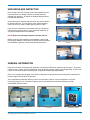
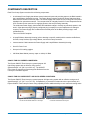
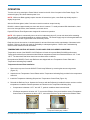
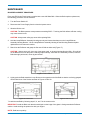
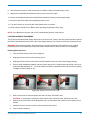
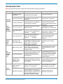
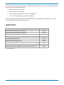
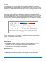
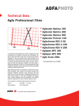
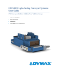
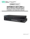
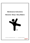
EC-Series Flood Lamps For Use with UVCS Series Conveyors EC-Series Flood Lamps (From left: 5000-EC for use with UVCS SideCure™ Conveyor (PN39798), 5000-EC for use with UVCS Conveyor (PN39241), EC Power Supply, and 2000-EC for use with UVCS Conveyor (PN38105) Operation Manual TABLE OF CONTENTS Unpacking and Inspection .......................................................................................................................... 3 General Information ................................................................................................................................... 4 Components Description ............................................................................................................................ 4 Specifications ............................................................................................................................................. 5 Installation and System Interconnect ......................................................................................................... 6 Operation.................................................................................................................................................... 7 Maintenance ............................................................................................................................................... 8 Troubleshooting ......................................................................................................................................... 11 Spare Parts List .......................................................................................................................................... 12 Definition of Terms ..................................................................................................................................... 13 Safety ......................................................................................................................................................... 14 Warranty ..................................................................................................................................................... 15 The enclosed Dymax EC-Series Flood Lamp System for UVCS-Series Conveyors was developed and manufactured by the Dymax team, driven by a desire to best serve your needs. Before shipping, your EC-Series Flood Lamp System was thoroughly checked and tested for trouble-free performance. The proper set up and operation of this Conveyor Flood Lamp System will maximize safety and user-friendly performance, providing optimum yield of your technological process. THEREFORE, WE ENCOURAGE YOU TO READ, UNDERSTAND, AND FOLLOW ALL SAFETY AND OPERATING INSTRUCTIONS AND RECOMMENDATIONS COMPILED IN THIS AND OTHER RELATED MANUALS prior to setting up and operating this new Flood Lamp System or its individual components. If you encounter a problem, have any questions, or would like to help us with your suggestions or recommendations, please contact Dymax Applications Engineering or Customer Service. 2 EC-Series Flood Lamps for UVCS-Series Conveyors UNPACKING AND INSPECTION Upon receipt of the unit, carefully remove the contents from the boxes and check for damage. Dymax is not responsible for damage from shipping – all claims for shipping damage should be made with the carrier. Check all boxes for contents and write down any serial numbers for further reference. You may wish to retain original shipping cartons in case you need to repackage any item for return. Figure 1. 5000-EC for UVCS Conveyor If you observe or experience any problem with your equipment, notify Dymax Customer Service, your authorized distributor, or your Dymax Representative immediately. NOTE: Report any shortage to Dymax Customer Service. Before continuing with unpacking and installation, please read the following chapters of this manual for safety recommendations and installation, operation, and troubleshooting instructions. Figure 2. 5000-EC for UVCS SideCure™ Conveyor Figure 3. 2000-EC for UVCS Conveyor GENERAL INFORMATION Dymax Flood Lamps are designed for installation into Dymax UVCS-Series Light-Curing Conveyors. They have extensive use in a wide variety of applications such as bonding, potting, sealing, and encapsulating. These Flood Lamps are extremely unique in that they offer exceptional versatility and expandability. Each unit is designed and shipped in a unitized configuration for easy bench-top mounting with all controls and functions right at the hands of the operator. The Lamp/Reflector Assembly Housing can be mounted side-by-side in a linear configuration on Dymax Conveyors (Figure 4 & 5). The Power Supplies can then be stacked and mounted remotely to provide consolidated operator control. Figure 4. 2000-EC mounted side by side on Conveyor EC-Series Flood Lamps for UVCS-Series Conveyors Figure 5. 5000-EC mounted side by side on Conveyor Figure 6. 5000-EC mounted on Side Cure Conveyor 3 COMPONENTS DESCRIPTION Each Flood Lamp System consists of the following components: A solid-state Power Supply that allows external electrical inputs and provides power to the Bulb located in the Lamp/Reflector Assembly Housing. The Power Supply contains the On/Off Power Switch and Hour Meter that are located on the front panel. The Power Supply also houses its own Cooling Fans and power distribution for optional accessories. The rear panel has an integrally fused AC Power Receptacle and an 8-Pin Female circular connector for supplying power to the Lamp Housing Assembly. The solid-state Power Supply yields reliable and stabilized voltage in virtually any electrical system in the world. Other than ensuring a properly configured plug is employed, no other adjustment of settings is required. The Power Supply also conditions the electrical power to the Bulb providing longer, more reliable Bulb life. This unit is RoHS Compliant. A Lamp/Reflector Assembly Housing (refer to drawing on specific models) which contains the Reflector, UV Bulb, Lamp Sockets, high-voltage Starter, and circular Lamp Connector. Interconnection Cable between the Power Supply and Lamp/Reflector Assembly Housing. One AC Power Cord. One pair of UV safety goggles. 400 Watt, Metal-Halide (mercury vapor or visible) UV Bulb. 2000-EC FOR UVCS SERIES CONVEYORS: The Dymax 2000-EC Flood Lamp is a general purpose UV light-curing system with an effective curing area of approximately 8" x 8" [20.3 cm x 20.3 cm]. The 2000-EC Flood Lamp is cooled by air flow through the Reflector from the Conveyor’s Ventilation System. Figure 7. 2000-EC Power Supply & Flood Lamp for use with the UVCS-Series Conveyors 5000-EC FOR UVCS SIDECURE™ AND UVCS-SERIES CONVEYORS: The Dymax 5000-EC Flood Lamp is a general purpose UV light-curing system with an effective curing area of approximately 5" x 5" [12.7 cm x 12.7 cm]. Comparatively, it provides more than twice the output intensity of a Dymax 2000-EC Flood Lamp for faster curing capability and the additional ability to cure conformal coating resins. Figure 8. 5000-EC Power Supply & Flood Lamp for use with the UVCS SideCure™ Conveyor 4 Figure 9. 5000-EC Power Supply & Flood Lamp or use with UVCS-Series Conveyors EC-Series Flood Lamps for UVCS-Series Conveyors SPECIFICATIONS Electrical Specifications – Power Supply Power Output Range Factory set to 395 Watts Operating Temperature 0-40°C Storage Temperature Operating Humidity -20-80°C 0-90% (non-condensing) Electrical Specifications – Flood Lamp Main Voltage 90-264 VAC Line Frequency 47-63 Hz Current Consumption (Maximum) @ 115 VAC @ 230 VAC Inrush Current (Maximum) Rated Output Power Output Protection 8 Amps 4 Amps 30 Amps 450 Watt maximum Short circuit and overload protected +24 Volts, 1 Amp available for Lamp Housing Fan and Shutters +/-24 Volts, ~0.5 Amp and +6 Volts unregulated PN38560 400 Watt, metal halide (standard) PN36970 400 Watt, mercury vapor (optional) PN36658 400 Watt, visible (optional) Auxiliary DC Outputs Bulb SPECTRAL INFORMATION: Spectral Outputs for DYMAX 400Watt Flood Bulbs Relative Intensity 38560 (Metal Halide) 36970 (Mercury) 36658 (Visible) 200 250 300 350 400 450 500 550 600 650 700 Wavelength Figure 10. Spectral Output for Dymax 400 Watt Bulbs EC-Series Flood Lamps for UVCS-Series Conveyors 5 2000-EC 5000-EC 5000-EC for use with UVCS-Series Conveyors for use with UVCS SideCure™ Conveyors Electrical Dimensions (Lamp/Reflector Assembly Housing) Weight Typical Output Intensity at UV-A* (320-395 nm) for use with UVCS-Series Conveyors See General Specifications 10.5" W x 9.0" D x 7.5" H 6.75" W x 6.75" D x 8.0" H 6.75" W x 6.75" D x 7.0" H [26.7 cm x 22.9 cm x 19.1 cm] [17.2 cm x 17.2 cm x 20.3 cm] [17.2 cm x 17.2 cm x 17.8 cm] 3.4 lbs. [1.5 kg] 2.7 lbs. [1.2 kg] 2.7 lbs. [1.2 kg] 75 mW/cm 2 225 mW/cm 2 225 mW/cm 2 * 2000-EC: Nominal intensity 2.1" below the Reflector; 5000-EC: Intensity 3" below bottom edge of Lamp/Reflector Assembly Housing. All measured with an ACCU-CAL™ 50 UV Radiometer calibrated and traceable to NIST. INSTALLATION AND SYSTEM INTERCONNECT 1. Place the 400 Watt UV Bulb into the Lamp/Reflector Assembly Housing (Figure 11). Refer to the Bulb Replacement/Installation Section of this manual. 2. Position the Power Supply so that there is free air circulation around the sides. The Lamp/Reflector Assembly Housing should be mounted to a Dymax Conveyor as described in the Conveyor's technical manual. WARNING! Always observe safety requirements when working with electrical equipment! Electrical hazard is present! 3. Connect the Interconnect Cable to the J3 Receptacle on the rear of the Lamp/Reflector Assembly Housing (Figures 11-13). Figure 11. Bulb in Lamp/Reflector Assembly Housing 4. Connect the opposite end of the Interconnect Cable to the Lamp Power Receptacle (Figure 14) on rear panel of the Power Supply. 5. Plug the AC Power Cord into the Power Module located in the rear panel of the Power Supply (Figure 14), and plug the opposite end of the AC Power Cord into appropriate external AC source. Lamp Power Receptacle Power Module Figure 12-13. Interconnect Cable in J3 Receptacle (From Left: 2000-EC Lamp/Reflector Assembly for UVCS-Series Conveyors, 5000-EC Lamp/Reflector Assembly for SideCure™ Conveyors, 5000-EC Lamp/Reflector Assembly for UVCS-Series Conveyors 6 Figure 14. Power Supply, Rear Panel EC-Series Flood Lamps for UVCS-Series Conveyors OPERATION Turn the unit on by pressing the Power Switch, located on the left of the front panel of the Power Supply. The switch will light up to indicate that the power is on. NOTE: While most Bulbs typically require less than 30 seconds to ignite, a new Bulb may initially require a slightly longer time. After the Bulb has ignited, allow 5 minutes to reach its maximum output intensity. Bulb life is reduced approximately one hour each time it is started. To avoid premature Bulb deterioration, leave the unit on through breaks, short shutdowns, and lunch hours. Dymax EC-Series Flood Systems are designed for continuous operation. NOTE: If the power is momentarily lost or the unit is inadvertently shut off, it must cool down before restarting. This may take 5-10 minutes depending on ambient conditions. The Power Supply may be left energized while the Bulb is cooling, and will re-ignite when it has sufficiently cooled. Each time the unit is turned on, it should operate for at least 30 minutes to allow vaporization of elements inside the Bulb. Failure to do this may result in unreliability in subsequent ignitions. Refer to the Troubleshooting Section of this manual for more information. TEMPERATURE CONTROL OF 5000-EC FLOOD LAMPS FOR UVCS-SERIES CONVEYORS Temperature control of the 5000-EC UVCS Reflector will result in improved Bulb (PN 38560) performance. Testing performed at Dymax shows that ideal Reflector temperature should be maintained between 115° F and 145° F. The instructions that follow show how to achieve these conditions. New-production 5000-EC Flood Lamp Reflectors are shipped with one Temperature Control Plate and a Temperature Indicating Strip installed. Temperature Control Plate Installation 1. Remove the top cover from the 5000-EC Flood Lamp Reflector by removing the two securing screws (Figure 15). 2. Unpack the two Temperature Control Plates and the Temperature Indicating Strip provided in the temperature control kit. 3. Install the Temperature Indicating Strip and one Temperature Control Plate (Figure 16). 4. Reinstall the Reflector Cover. Operate the Conveyor with the Reflector(s) installed for about one hour to allow temperatures to stabilize. Read temperature as indicated on the Temperature Indicating Strip. If temperature is between 115° F and 145° F, optimum conditions have been achieved. If Reflector temperature is below 115° F, remove the Reflector Cover and install the second Temperature Control Plate. If temperature is above 145° F, remove the Reflector Top and remove the Reflector Plate. Securing Screws Figure 15. 5000-EC EC-Series Flood Lamps for UVCS-Series Conveyors Figure 16. Temperature Control Plate and Temperature Indicating Strip, installed 7 MAINTENANCE BULB REPLACEMENT PROCEDURE Every new EC-Series Flood Lamp is supplied with a new 400 Watt Bulb. When the Bulb requires replacement, the following procedure must be followed. 1. Turn the Power Switch off. 2. Disconnect the Power Supply from the electrical power source. 3. Allow the Bulb to cool. CAUTION: The Bulb operates at temperatures exceeding 500°C. Touching the Bulb before sufficient cooling may cause severe burns. CAUTION: Always wear safety eye wear while replacing Bulb. 4. Hold the Lamp/Reflector Assembly Housing securely and loosen thumbscrew on the Lamp/Reflector Assembly Housing Bracket. Lift the Lamp/Reflector Assembly Housing off the Mounting Stand and place upside down on a clean work surface. 5. Reach into the Reflector and grasp the flat area of Bulb at either end (Figure 17). CAUTION: Always use a soft, clean rag, clean paper towel, or gloves when handling the Bulb. Skin oils left on the Bulb will burn into the quartz, reducing output intensity. If the Bulb is inadvertently touched, clean the Bulb thoroughly with a soft, clean rag and alcohol. Figure 17. Bulb in Reflector 6. Lightly push the Bulb toward the Lamp Socket on the opposite end of the Bulb so that the end being grasped can be lifted clear of the Socket as shown in Figures 18 and 19. Figure 18. Bulb Removal Figure 19. Bulb Removal 7. Install the new Bulb by following steps 5, 6, and 7 in the reverse order. IMPORTANT: Install the Bulb such that the seal dimple on the bulge of the glass is facing towards the Reflector surface. Avoid touching the quartz tube with your fingers. NOTE: Bulb has no polarity. 8 EC-Series Flood Lamps for UVCS-Series Conveyors 8. Record the serial number of the unit and the Hour Meter reading in the Bulb history record. 9. Replace the Lamp/Reflector Assembly Housing on the Conveyor Cradle. 10. Secure the thumbscrew when the Lamp/Reflector Assembly Housing is at the proper height. 11. Reconnect the Power Cord to the appropriate power source. 12. Turn the Conveyor on by turning the Power Switch to the on position. 13. Allow at least 5 minutes for the Bulb to reach operating temperature before using. NOTE: If the Bulb does not ignite, refer to the Troubleshooting Section of this manual. FUSE REPLACEMENT PROCEDURE The EC-Series 400 Watt Power Supply utilizes two Line-Input Fuses. These Fuses are external and are located in the Power Cord Receptacle at the rear of the Power Supply Housing. The Fuses are 6.25 Amp, slow-blow Fuses. WARNING: Electrical shock hazard. Exercise extreme care when replacing Fuses. Make sure only qualified personnel perform Fuse replacement and that all Power Switches are off and the Power Cord is unplugged. Replacing External Fuses: 1. Turn the Power Switch on the Power Supply off. 2. Unplug the Power Cord from the electrical source. 3. Unplug the Power Cord from the Power Cord Receptacle at the rear of the Power Supply Housing. 4. Place a small, flat-blade screwdriver into the notch at the top of the Plug Recess and pull the Fuse Cover downwards approximately 70°. The Fuse Retainer should be exposed and should be removed by pulling it straight out (see Figures 12-14). Plug Recess Fuse Cover Figure 12-14. Replacing Fuses in the Power Supply 5. Slide out the blown Fuses and replace with new 6.25 Amp, slow-blow Fuses. CAUTION: It is important to replace this Fuse with the same 6.25 Amp rated, slow-blow type Fuse. 6. Slide the Fuse Cover back into the Receptacle until it is fully seated, then rotate the cover upward until it latches. 7. Install the Power Cord and connect it to the electrical power source. 8. Turn the Power Switch on. EC-Series Flood Lamps for UVCS-Series Conveyors 9 CLEANING: Periodically clean the Bulb and Reflector surfaces. A soft, clean cloth and any standard glass cleaner should be used. Heavier deposits may require cleaning with isopropyl alcohol. CAUTION: Cleaning the Reflector with a rough or dirty cloth will result in a dulled surface, thereby, reducing reflectance and decreasing UV output. Use only a soft, clean cloth. Any uncured resins spilled onto the system can be removed with isopropyl alcohol and a clean cloth. 10 EC-Series Flood Lamps for UVCS-Series Conveyors TROUBLESHOOTING NOTE: Only qualified maintenance personnel should attempt the following procedures. Problem Possible Cause Testing Corrective Action Improperly fastened connections Visually inspect all connections to and from the Power Supply. Secure all connections. Main Line Fuses blown Remove Fuses from Power Receptacle and check with an Ohmmeter. Replace Fuses, if defective. Corroded Lamp Bases Visually inspect the Lamp Bases for any signs of corrosion. Replace the Lamp Bases if corrosion exists (both Lamp Bases should be replaced at the same time). Bulb beyond useful life Replace Bulb with (known) good Bulb and re-test. Replace Bulb if defective (typical Bulb life = 2,000 hours). Power Supply Board failed Check UV output voltage on power supply board. Set Oscilloscope to: 20ms/div 100V/div Expected value 290-340 Vrms Square Wave. Replace Power Supply Board if defective. Igniter malfunctioned Verify open circuit voltage from igniter. Set Oscilloscope to: 50us/div 1000V/div Expected value 4-5 KV ignition pulse superimposed on the square wave. Replace if defective. Bulb Will Not Ignite or Bulb Flickers, Won’t Maintain Operation Unit Blows Input Fuse Malfunction in the Power Supply Board Bulb beyond its useful life UV Intensity Appears To Be Low Remove power. Disconnect the Lamp/Reflector Assembly from the Power Supply. Replace the Fuse. Apply power. If Fuse blows, Power Supply is defective. Use a Radiometer (Dymax ACCUCAL™ 50) to measure actual output intensity. Consult manual for proper output. Replace the Power Supply Board. Replace Bulb if beyond useful life (typical Bulb life = 2,000 hours). The Quartz Envelope on Bulb is contaminated Visually inspect the Bulb for signs of contamination (the Quartz Envelope must be free from any contamination). Clean the Bulb with a soft, lintfree cloth and isopropyl alcohol. Bulb may need to be replaced if contamination is burned into Quartz Envelope. Surfaces of the Reflector may be contaminated Examine the Reflector surface for contaminants. It should be a clean, shiny surface. Clean the Reflector with a soft, lint-free cloth and isopropyl alcohol, or equivalent. Bulb is overcooled (5000 UVCS and SideCure™) Verify that reflector temperature is between 115°F and 145°F. Install ventilation control plates as described in this manual. Degraded Lamp Bases Visually inspect both Lamp Bases and the electrical contacts on each end of the Bulb. The Lamp Base and the electrical contacts on each end of the Bulb should show no corrosion or evidence of arcing. Replace Lamp Bases as described in this manual. Short Bulb Life EC-Series Flood Lamps for UVCS-Series Conveyors 11 NOTE: When contacting Dymax Corporation, an authorized Dymax distributor, or manufacturer’s representative, be sure to know and provide the following: Model number of unit in question. Serial number of unit in question. Product number of the adhesive in question (if applicable). Lot number of the adhesive in question (if applicable). All returns to Dymax Corporation must be accompanied by a return authorization number (RAN). This number must be obtained from Dymax Customer Service. SPARE PARTS Item Part # Bulb, Metal Halide 400 Watt UV (Standard)* 38560 Bulb, Mercury Vapor 400 Watt UV (Optional) 36970 Bulb, Visible Flood 400 Watt (Optional) 36658 Fuse, F 6.25 Amp* 35141 Lamp Base Replacement Kits* 35979 UV-Blocking Safety Goggles, Gray 35285 UV-Blocking Safety Goggles, Clear 35612 Power Switch 36288 Temperature Control Kit (5000 UVCS and 5000 UVCS SideCure™) 38693 * Recommended spare parts 12 EC-Series Flood Lamps for UVCS-Series Conveyors DEFINITION OF TERMS Flood Lamp System - Set of components arranged to generate, collect, condition and direct UV radiant energy to perform curing of engineering adhesives, coatings, and inks within a safe and controlled process. It includes a Lamp Housing and Power Supply and may also include a Shutter, Workstation, UV Enclosure, Light Shield, and/or accessories. Bulb - Light source (bulb or burner) generating ultraviolet, visible, and infrared radiant energy from burning matter stimulated by electrical power conditioned by a proper power supply which is an integral part of a Lamp. A light source is usually placed into a reflector (of various geometry) to increase light source efficiency by collecting and directing radiant energy of selected spectra (for a given curing process). Intensity - A measure of light energy over the unit of surface area (usually surface at the specified working 2 2 distance from the bottom of a Reflector Housing) in W/cm or mW/cm . For the UV portion of light, this measure is often called in literature “irradiance”, i.e. radiant energy arriving at a point on a surface per unit area. Brightness, also known as Luminance - Description of energy in the visible region of the spectrum (approximately from 400 to 700 nm) and recorded in photometric units. “Intensity” (see below) of visible light energy is called Illuminance. Illuminance - Luminous flux (energy of visible light) incident per unit area, and measured in Lx (lux) or 2 Lumen/cm . Ultraviolet (UV) - The invisible region of the spectrum just beyond the violet end of the visible region. Wavelength ranges in general from 1.0 to 400 nm. Dymax Bulbs (burners) do not radiate energy in deep ultraviolet; there are very minute amounts below 220 nm and practically nothing can be sensed below 200 nm. This is due to the use of ozone-blocking Quartz Bulb Envelope (See Ozone). Ultraviolet is used beneficially in various fields of industry and medicine. In order to standardize light sources used in medicine, the International Congress on Light in Copenhagen in 1932 recommended dividing the ultraviolet spectrum into three spectral parts: 1. Ultraviolet A (UV-A) - UV of long wavelength from within approximately 400 to 320 nm of the spectral band (4000 to 3200) - predominately produced by Dymax Flood Lamps. 2. Ultraviolet B (UV-B) - UV of medium wavelength from within approximately 320 to 280 nm - Dymax Flood Lamps produce some amount of their energy within this bandwidth. 3. Ultraviolet C (UV-C) - UV of short wavelength below 280 nm (we say from 280 to 200 nm) – a large amount of this energy is present in the sunlight. 2 2 Dose - Irradiance integrated over time, or Irradiance (W/cm ) x Time (s) = Dose (Joules/cm ). Note: Watt is the power that gives rise to the production of energy at the rate of 1-joule (J) per second(s). Ozone - Oxidizing agent (O3) produced by the action of ultraviolet radiant energy (below 185 nm) or electrical corona discharge of oxygen on air. OSHA 1910.145: “Regulation of Accident prevention Signs and Tags” defines the following headers as: WARNING – is used when there is a hazardous situation that has some probability of severe injury. CAUTION - is used to indicate a hazardous situation that may result in minor or moderate injury. NOTICE - is used to convey a message related directly or indirectly to the safety of personnel, or protection of property. EC-Series Flood Lamps for UVCS-Series Conveyors 13 SAFETY Dymax ultraviolet light-curing technology has been used successfully for over 30 years. The fast cure, onecomponent nature of our UV light-curing technology has made it the process of choice for many manufacturers requiring a "cure on demand" assembly process. There are four common questions/concerns related to UV lightcuring systems: UV exposure, high-temperature surfaces, ozone, and bright, visible light. UV EXPOSURE Standard Dymax UV light-curing systems and bulbs have been designed to primarily emit UVA light (as shown in Chart 1). UVA light is generally considered the safest of the three UV ranges: UVA, UVB, and UVC. Although OSHA does not currently regulate ultraviolet light exposure in the workplace, the American Conference of Governmental Industrial Hygienists (ACGIH) does recommend Threshold Limit Values (TLVs) for ultraviolet light. 2 The strictest interpretation of the TLV (over the UVA range) for workers’ eyes and skin is 1 mW/cm (intensity), continuous exposure. Unless workers are placing bare hands into the curing area, it is unusual to exceed these 2 2 limits. To put 1 mW/cm limit into perspective, cloudless summer days in Connecticut regularly exceed 3 mW/cm of UVA light and also include the more dangerous UVB light (primarily responsible for sun tans, sun burns, and skin cancer) as well. Chart 1. Light Spectrum The human eye can not detect “pure” UV light, only visible light. A radiometer should be used to measure stray UV light to confirm the safety of a UV curing process. A workstation that exposes an operator to more than 2 1 mW/cm of UVA continuously should be redesigned. Curing of UV light-curable adhesives can be a regulatory compliant, “worker-friendly” manufacturing process when the proper safety equipment and operator training is utilized. There are two ways to protect operators from UV exposure: shield the operator and/or shield the source. Shield the Operator UV-Blocking Eye Protection – UV-blocking eye protection is recommended when operating UV lightcuring systems. Both clear and tinted UV-blocking eye protection is available from Dymax. UV-Blocking Skin Protection – Where the potential exists for UV exposure upon skin, opaque, UVblocking clothing, gloves, and full-face shields are recommended. Shield the Source of UV Any substrate that blocks UV light can be used as a shield to protect workers from stray UV light. The following materials can be used to create simple shielding structures or blind corners: 14 Sheet Metal – Aluminum, steel, stainless steel, etc. Sheet metal should be coated black or black anodized to minimize reflection of UV and visible light toward operators. EC-Series Flood Lamps for UVCS-Series Conveyors Rigid Plastic Film – Transparent, UV-blocking plastics (typically polycarbonate or acrylic) are commonly used to create shielding where transparency is also desired. These rigid plastic films are available either water-clear or tinted. Flexible Film – UV-blocking, flexible urethane films can be used to quickly create workstation shielding. This UV-blocking, flexible urethane film is available from Dymax. HIGH-TEMPERATURE SURFACES Surfaces exposed to high-intensity curing lights will rise in temperature. The intensity, distance, exposure time, cooling fans, and the type/color of the surface can all affect the actual surface temperature. In some cases, exposed surfaces can reach temperatures capable of producing a burn or causing damage to a substrate. In these cases, care must be taken to ensure either a more moderate surface temperature or appropriate protection/training for operators. OZONE Standard Dymax bulbs (UVA type) generate an insignificant amount of UVC and therefore essentially no ozone. Some UV light-curing systems, like those used to cure UV light-curable inks, emit primarily “shortwave” (UVB and UVC) energy. Upon exposure to UVC light (specifically <240 nm), oxygen molecules (O2) split into oxygen atoms (O) and recombine with O2 to create ozone O3. The current, long-term ozone concentration limit recommended 3 by ACGIH, NIOSH, and OSHA is 0.1 ppm (0.2mg/m ). BRIGHT, VISIBLE LIGHT The bright, visible light emitted by some UV light-curing systems can be objectionable to some workers and can cause eyestrain. Tinted eye protection and/or opaque/tinted shielding can be utilized to address this concern. SUMMARY UV light sources can be more “worker friendly” than many commonly accepted industrial processes, provided the potential concerns are addressed. Contact your Dymax representative for information regarding the proper use of Dymax UV light-curing systems. WARRANTY Log-on to www.dymax.com/warranty for on-line warranty registration. This will ensure that you are notified of any updates regarding this unit. CAUTION! DYMAX CORPORATION RESERVES THE RIGHT TO INVALIDATE ANY WARRANTIES, EXPRESSED OR IMPLIED, DUE TO ANY REPAIRS PERFORMED OR ATTEMPTED ON DYMAX EQUIPMENT WITHOUT WRITTEN AUTHORIZATION FROM DYMAX. THOSE CORRECTIVE ACTIONS LISTED BELOW ARE LIMITED TO THIS AUTHORIZATION. Dymax offers a one-year warranty against defects in material and workmanship on all system components with proof of purchase date. Unauthorized repair, modification, or improper use of equipment may void warranty. The use of aftermarket replacement parts not supplied or approved by Dymax Corporation, will void any effective warranties and may result in damage to the equipment. EC-Series Flood Lamps for UVCS-Series Conveyors 15 © 2006-2011 Dymax Corporation. All rights reserved. All trademarks in this guide, except where noted, are the property of, or used under license by Dymax Corporation, U.S.A. Please note that most dispensing and curing system applications are unique. Dymax does not warrant the fitness of the product for the intended application. Any warranty applicable to the product, its application and use is strictly limited to that contained in Dymax’s standard Conditions of Sale. Dymax recommends that any intended application be evaluated and tested by the user to insure that desired performance criteria are satisfied. Dymax is willing to assist users in their performance testing and evaluation by offering equipment trial rental and leasing programs to assist in such testing and evaluations. Data sheets are available for valve controllers or pressure pots upon request. MAN008 PN39809 1/21/2011 Dymax Corporation 860.482.1010 [email protected] www.dymax.com Dymax Oligomers &Coatings 860.626.7006 oligomers&[email protected] www.dymax-oc.com Dymax Europe GmbH +49 (0) 611.962.7900 [email protected] www.dymax.de Dymax UV Adhesives & Equipment (Shenzhen) Co Ltd +86.755.83485759 [email protected] www.dymax.com.cn Dymax UV Adhesives & Equipment (Shanghai) Co Ltd +86.21.37285759 [email protected] www.dymax.com.cn Dymax Asia (H.K.) Limited +852.2460.7038 [email protected] www.dymax.com.cn Dymax Korea LLC 82.2.784.3434 [email protected] www.dymax.co.kr