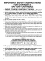
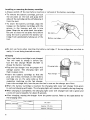
1
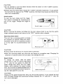
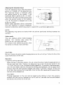
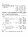
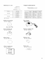
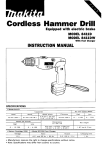
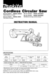
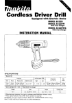
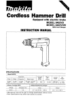
Cordless Percussion-Driver Drill
Equipped with electric brake
MODEL 8412D
MODEL 8412DW
With Fast Charger
INSTRUCTION MANUAL
No load speed 1RPMI
Capacltlcs
stce1
COllCrele
1"
,,1n1
(3,8"I
1.3
mm
(i/z")
High
-
0
2 4 mrn ( 1 5 / 1 6 " )
Battery Cartridge 1201
I
-
0
v
:~,",?,gT
3 1 3 mm x 7 9 mm x 2 2 5 mm
112~318" x 3 118" x 8 718"l
4.100
0
LOW
1.150
0
370
2 2 k g 14 9 Ibsl
Model DC1201 Fast Charger
vo1tagc
12
4
m
;l::
1L x W x H I
Low
12,700
High
Wood screw
WOOd
Input
A C
only 50 H r
60 Hr
Output
Charging lime
D C 96V. 12V
1 Hr.
IMPORTANT
SAFETY INSTRUCTI0NS
(For All Tools)
WARNING: WHEN USING ELECTRIC TOOLS, WSlC SAFETY
PRECAUTIONS SHOULD ALWAYS BE FOLLOWED TO REDUCE
THE RISK OF FIRE, ELECTRIC SHOCK, AND PERSONAL
INJURY, INCLUDING THE FOLLOWING:
READ ALL INSTRUCTIONS.
1. KEEP WORK AREA CLEAN. Cluttered areas and benches invite injuries.
2. CONSIDER WORK AREA ENVIRONMENT. Don't use power tools in damp
or wet locations. Keep work area well lit. Don't expose power tools t o rain.
Don't use tool in presence of flammable liquids or gases.
3. KEEP CHILDREN AWAY. All visitors should be kept away from work area.
Don't let visitors contact tool or extension cord.
4. STORE IDLE TOOLS. When not in use, tools should be stored in dry, and high
or locked-up place - out of reach of children.
5. DON'T FORCE TOOL. It will do the job better and safer at the rate for which
it was intended.
6. USE RIGHT TOOL. Don't force small tool or attachment t o do the job of a
heavy-duty tool. Don't use tool for purpose not intended; for example, don't
use circular saw for cutting tree limbs or logs.
7. DRESS PROPERLY. Don't wear loose clothing or jewelry. They can be caught
i n moving parts. Rubber gloves and non-skid footwear are recommended
when working outdoors. Wear protective hair covering t o contain long hair.
8. USE SAFETY GLASSES. Also use face or dust mask if cutting operation is
dusty.
9. DON'T ABUSE CORD. Never carry tool by cord or yank it t o disconnect from
receptacle. Keep cord from heat, oil, and sharp edges.
IO. SECURE WORK.
Use clamps or a vise t o hold work. It's safer than using
your hand and it frees both hands t o operate tool.
1 1 . DON'T OVERREACH. Keep proper footing and balance at all times.
12. MAINTAIN TOOLS WITH CARE. Keep tools sharp and clean for better and
safer performance. Follow instructions for lubricating and changing accessories. Inspect tool cords periodically and if damaged, have repaired by authorized service facility. Inspect extension cords periodically and replace if
damaged. Keep handles dry, clean, and free from oil and grease.
13. DISCONNECT TOOLS. When not in use, before servicing, and when changing accessories, such as blades, bits, cutters.
14. REMOVE ADJUSTING KEYS AND WRENCHES. Form habit of checking t o
see that keys and adjusting wrenches are removed from tool before turning
it on.
15. AVOID UNINTENTIONAL STARTING. Don't carry tool w i t h finger on switch.
Be sure s w i t c h is OFF when plugging in.
16. OUTDOOR USE EXTENSION CORDS. When tool is used outdoors, use only
extension cords intended for use outdoors and
so marked.
17. STAY ALERT. Watch what you are doing, use common sense. Don't operate
tool when you are tired.
18. CHECK DAMAGED PARTS. Before further use of the tool, a guard or other
part that is damaged should be carefully checked t o determine that it will
operate properly and perform its intended function. Check for alignment of
moving parts, binding of moving parts, breakage of parts, mounting, and any
other conditions that may affect its operation. A guard or other part that
is damaged should be properly repaired or replaced by an authorized service center unless otherwise indicated elsewhere in this instruction manual.
Have defective switches replaced by authorized service center. Don't use
tool if switch does not turn it on and off.
19. GUARD AGAINST ELECTRIC SHOCK. Prevent body contact w i t h grounded
surfaces. For example; pipes, radiators, ranges, refrigerator enclosures.
20. REPLACEMENT PARTS. When servicing, use only identical replacement parts.
21. POLARIZED PLUGS. To reduce the risk of electric shock, this equipment has
a polarized plug (one blade is wider than the other). This plug will f i t in a
polarized outlet only one way. If the plug does not f i t fully in the outlet,
reverse the plug. If it still does not fit, contact a qualified electrician t o install
the proper outlet. Do not change the plug in any way.
VOLTAGE WARNING: Before connecting the tool t o a power source (receptacle,
outlet, etc.) be sure the voltage supplied is the same as that specified on the
nameplate of the tool. A power source w i t h voltage greater than that specified
for the tool can result in SERIOUS INJURY t o the user - as well as damage t o
the tool. If in doubt, DO NOT PLUG IN THE TOOL. Using a power source w i t h
voltage less than the nameplate rating is harmful t o the motor.
IMPORTANT SAFETY INSTRUCTIONS
FOR CHARGER &
BATTERY CARTRIDGE
I. SAVE THESE INSTRUCTIONS - This manual
Length of Cord (Feet)
AWG Size of Cord
4
25
18
50
18
100
18
150
16
ADDITIONAL SAFETY RULES
FOR CHARGER & BATTERY CARTRIDGE
1. Do not charge Battery Cartridge when temperature is BELOW 10°C (5OOF)
or ABOVE 4OoC (104OF).
2. Do not attempt t o use a step-up transformer, an engine generator or DC power
receptacle.
3.Do not allow anything t o cover or clog the charger vents.
4. Always cover the battery terminals with the battery cover when the battery
cartridge is not used.
5. A battery short can cause a large current flow, overheating, possible burns
and even a breakdown.
(1) Do not touch the terminals w i t h any conductive material.
(2) Avoid storing battery cartridge in a container with other metal objects
such as nails, coins, etc.
(3) Do not expose battery cartridge t o water or rain.
6. Do not store the tool and Battery Cartridge in locations where the temperature may reach or exceed 5OoC (122OF).
7. Do not incinerate the Battery Cartridge even if it is severely damaged or is
completely worn out. The battery cartridge can explode in a fire.
ADDITIONAL SAFETY RULES
1. Be aware that this tool is always in an operating condition, because it does
not have t o be plugged into an electrical outlet.
2. Wear a hard hat (safety helmet), safety glasses andlor face shield. It is also
highly recommended that you wear a dust mask, ear protectors and thickly
padded gloves.
3. Under normal operation, the tool is designed t o produce vibration. The screws
can come loose easily, causing a breakdown or accident. Check tightness of
screws carefully before operation.
4. Always be sure you have a firm footing.
Be sure no one is below when using the tool in high locations.
5. Hold the tool firmly.
6. Keep hands away from rotating parts.
7. Do not leave the tool running. Operate the tool only when hand-held.
8. When drilling into walls, floors or wherever "live" electrical wires may be
encountered, DO NOT TOUCH ANY METAL PARTS OF THE TOOL!
Hold the tool by the insulated grasping surfaces t o prevent electric shock if
you drill into a "live" wire.
9. Do not touch the bit or the workpiece immediately after operation; they may
be extremely hot and could burn your skin.
SAVE THESE INSTRUCTIONS.
5
.To remove the battery cartridge, pull out
the set plate on the tool and grasp both
sides of the cartridge while withdrawing it
from the tool.
* T o insert the battery cartridge, align the
tongue on the battery cartridge with the
groove in the housing and slip it into
place. Snap the set plate back into place.
Be sure to close the set plate fully before
using the tool to prevent the battery cartridge from accidentally falling out of the
tool.
Set plate
Battery cartridge
Do not use force when inserting the battery cartridge. If the cartridge does not slide in
easily, it is not being inserted correctly.
Charging
Your new battery cartridge is not charged.
You will need to charge it before use.
Use the fast charger Model DC1201 to
charge the battery cartridge.
.Plug the fast charger into the proper A/C
voltage source. The charging light will
flash in green color.
.Insert the battery cartridge so that the
plus and minus terminals on the battery
cartridge are on the same sides as their
respective markings on the fast charger.
Insert the cartridge fully into the port so that it rests on the charger port floor.
When the battery cartridge i s inserted, the charging light color will change from green
to red and charging will begin. The charging light will remain lit steadily during charging.
When charging is completed, the charging light color will change from red to green and
a tone will sound steadily for about 5 seconds.
After charging, unplug the charger from the power source. Refer to the table below for
the charging time.
DC1201
1200
I
6
1201
Approx. 45 min.
I
ADDrox. 60 min.
I
CAUTION :
*The fast charger Model DC1201 is specifically designed to charge only Makita battery
cartridges. Never use it for other purposes or for other manufacturer's batteries.
0 When you charge a new battery cartridge or a battery cartridge which has not been used
for a long period of time, it may not accept a full charge. This is a normal condition and
does not indicate a problem. You can recharge the battery cartridge fully after discharging it completely and recharging a couple of times.
0 I f you charge a battery cartridge from a just-operated tool or a battery cartridge which
has been left in a location exposed to direct sunlight or heat for a long time, the charging light may flash in red color. If this occurs, wait for a while. Charging will begin after
the battery cartridge cools.
0 I f the charging light flashes alternately in green and red color and a tone sounds "beep,
beep, beep, . .
for about 20 seconds, a problem exists and charging i s not possible.
The terminals on the charger or battery cartridge are clogged with dust or the battery
cartridge i s worn out or damaged.
0 I f you wish to charge two battery cartridges, allow 15 minutes between chargings on the
fast charger.
.'I
Installing or removing the drill bit or driver bit
CAUTION :
Always be sure that the tool is switched off and the battery cartridge i s removed before
installing or removing the bit.
To install the bit, push the sleeve up toward the "FREE" side and turn the sleeve
counterclockwise while holding the ring
with your other hand as illustrated a t right.
Place the bit in the chuck as far as it will
go. Hold the ring firmly and turn the sleeve
clockwise to tighten the chuck. Then push
the sleeve down toward the "LOCK" side.
To remove the bit, push the sleeve up toward the "FREE" side and turn the sleeve
counterclockwise while holding the ring with your other hand.
7
CAUTION :
0 Do not attempt to turn the sleeve forcibly when the sleeve i s in the "LOCK" position.
The chuck may be damaged.
Always push the sleeve down toward the "LOCK" side before operation. If you operate
the tool with the sleeve in the "FREE" position, the chuck may loosen and the bit may
come out unexpectedly.
Switch action
To start the tool, simply pull the trigger.
Tool speed is increased by increasing pressure on the trigger. Release the trigger to
stop.
Switch trigger
1I
21;
CAUTION :
Before inserting the battery cartridge into the tool, always check to see that the switch
trigger actuates properly and returns to the "OFF" position when released.
Reversingswitch action
This tool has a reversing switch to change
the direction of rotation. Move the reversing switch to the left for clockwise rotation
or to the right for counterclockwise rotation.
\
Reversing switch
1
1'8
I
CAUTION :
Always check the direction of rotation before operation.
0 Move the reversing switch only after the tool comes to a complete stop. Changing the
direction of rotation before the tool stops. may damage the tool.
Speed change
To change the speed, slide the speed
change lever to the "2" side for high speed
or "1" side for low speed. To slide the
speed change lever easily, pull the trigger
slightly while pushing the speed change
lever. Be sure that the speed change lever i s
set to the correct position before operation.
Use the right speed for your job.
CAUTION:
Always set the speed change lever fully into the correct position. I f you operate the tool
with the speed change lever positioned halfway between the "2" side and "1" side, the
tool may be damaged.
8
Adjusting the fastening torque
Turn the adjusting ring so that the pointer
points to a number on the adjusting ring.
The fastening torque is minimum when
the pointer points to the number 1 and
maximum when it points to the
mark.
The clutch will slip a t varying torque levels
when the pointer points to the numbers
1 to 10. The clutch i s designed not to slip
a t the 6
”
mark.
Before actual operation, drive a trial screw
into your mateiral or a piece of duplicate
~~
-_
L
Adjusting l i n g __
L
p
NOTE :
The adjusting ring cannot be locked with the pointer positioned halfway between the
numbers.
Action mode
This tool employs action mode changing
buttons. For rotation only, press the
button on the O-LV mark side fully.
For rotation with hammering action, press
the button on the @I mark side fully.
A c t i o n mode
changing b u t t o n
k-
CAUTION :
Be sure to press the action mode changing button as far as it will go. Failure to do so may
cause malfunction of the tool.
Operation
1 ) Hammer drilling operation
When drilling in concrete, granite, tile, etc., press the action mode changing button on
the
mark side fully. Position the adjusting ring so that the pointer points to the
mark. Be sure to use a tungsten-carbide tipped bit. To position a hole accurately,
start the tool slowly and then increase the drilling speed gradually. Do not apply more
pressure when the hole becomes clogged with chips or particles. Instead, run the tool
a t an idle, then remove the bit partially from the hole. By repeating this several times,
the hole will be cleaned out.
CAUTION :
Pressing excessively on the tool will not speed up the drilling. In fact, this excessive
pressure will only serve to damage the tip of your bit, decrease the tool performance
and shorten the service life of the tool.
9
After drilling the hole, use the blow-out
bulb to clean the dust out of the hole.
2) Drilling operation
When drilling in wood, metal or plastic materials, press the action mode changing
button on the a== mark side fully. Position the adjusting ring so that the pointer
points to the 6-q mark.
0
0
Drilling in wood
When drilling in wood, best results are obtained with wood drills equipped with a
guide screw. The guide screw makes drilling easier by pulling the bit into the workpiece.
Drilling in metal
To prevent the bit from slipping when starting a hole, make an indentation with a
centerpunch and hammer a t the point to be drilled. Place the point of the bit in the
indentation and start drilling. Use a cutting lubricant when drilling metals. The exceptions are iron and brass which should be drilled dry.
CAUTION :
Pressing excessively on the tool will not speed up the drilling. In fact, this excessive
pressure will only serve to damage the tip of your bit, decrease the tool performance
and shorten the service life of the tool.
0 There is a tremendous twisting force exerted on the tool/bit a t the time of hole breakthrough. Hold the tool firmly and exert care when the bit begins to breakthrough the
workpiece.
0 A stuck bit can be removed simply by setting the reversing switch to reverse rotation
in order to back out. However, the tool may back out abruptly if you do not hold it
firmly.
0 Always secure small wokpieces in a vise or similar hold-down device.
0
3) Screwdriving operation
When driving wood screws or machine
screws, press the action mode changing
button on the a== mark side fully.
Adjust the desired torque by turning the
adjusting ring. Place the point of the
driver bit into the screw head and apply
pressure to the bit. Start the tool slowly
and then increase the driving speed
gradually. Release the trigger as soon as
the clutch slips.
10
When driving wood screws, predrill pilot
holes to make driving easier and to
prevent splitting of the workpiece. See
the chart at right.
Recommended size
of pilot hole Imml
2 2 15/64"
3/32',)
2.5 (3132''
3/32")
Nomlnal diameter of
screw I")
3 1 1118")
2 0
3 . 5 19164")
3.8 15/32"]
4.5 (1 1/64")
2.2
(3116")
I1 3/64',)
17/32")
115164"l
6 1 (15164")
fi 4 I1 14")
4.8
5 1
5 5
5 8
~~
~
~
2.5 2.9
3 1
3 3
36
I
I
I
~~
~
~
4 0
4 2
A 4
~
2 . 8 13/32"
~
3.4 (118''
3 . 6 11/8"
3 9 19/64"
4 2 15/37"
~
~
~
~
~~
~
7/64")
118")
~
3 2 (7164''
9/64"!
9/64")
5/32")
11164"l
4.4 11 1164"
4 fi I1 l i f i A "
11/64")
~
?/lfi")
*Occasionally the adjusting ring cannot be reset to the OW mark after screwdriving
operation. If this occurs, let the clutch slip or turn the chuck by your hand.
Drilling, hammer drilling and screwdriving performance
The following reference table indicates the approximate drilling, hammer drilling and
screwdriving capacities from a single 1 hour battery charge. It may differ under some
condition.
Application
Metal
Bit diameter
1
6.5 mm (114'7
1 0 mm 13/8")
Workpiece
Cold-rolled steel sheet
or plate
1 0 mm 1318")
Aluminum sheet
I
Thickness
1 8 mm ( 1 1116")
24
Masonry
(Hammer
drilling)
Application
6.5 mm 1114")
9.5 mm 13/8"1
-
1.6 mm 11/16")
Approx. 1 3 0
Approx. 1 8 0
Approx. 11 5
Approx. 1 6 0
Approx. 7 0
Approx. 95
Brick
3 0 mm (1~3116")
510ck
3 0 mm j 1-3116 " )
Workpiece
5 1 mm x 3 5 mm (3116" x 1~318")
~
5 . 5 mm x 50 mm (7132" x 2")
6 4 mm x 50 mm (1/4" x 2 " )
Approx. 35
Approx. 4 5
Approx. 2 5
Approx. 25
Approx. 3 5
Approx. 3 5
Approx. 1 2
Approx. 1 6
Fastenings
h n e n s i o n s of wood screw
4.5 mm x 2 0 mm 13/16" x 314")
Wood
scrcws
Batterv 1201
Approx 8 0
Approx 35
m m (15116")
9.5 mm 1318")
I
Approx 60
Approx 25
2 5 mm (1")
Lauan wood
No. holes
Batterv 1200
1,6 mm 11,16,,1
15 mm 1518")
Wood
1
Lauan wood
Battery 1200
Battery 1201
Approx. 4 4 0
Approx. 610
Approx. 1 0 0
Approx. 140
Approx. 70
Approx. 90
Approx. 4 0
Approx.
50
11
MAINTENANCE
CAUTION :
Always be sure that the tool is switched off and the battery cartridge i s removed before
attempting to perform inspection or maintenance.
To maintain product SAFETY and RELlABl LITY, repairs, maintenance or adjustment
should be performed by Makita Authorized or Factory Service Centers, always using
Makita replacement parts.
Pari No.
Size
784201-5
No. 1
L lmm)
65 (2-518“)
784202~3
45 I 1 ~314”)
784203-1
No. 2
1 10 (4~318“)
784207-3
150 15-7/8”)
784221 -9
250 I 1 0”)
784208-1
784209 9
45 11~314”)
65 12-518”)
No. 3
~
110 14-318“)
784210-4
Part
No,
I
Size
784204~9 No. 2
0.81.031”)
65 (2.518”)
784206-5
I
L (mm)
I
D lmm)
I
d Imm)
82 13-114”) 6 1114”) 5 (3116”)
Drill bit (For wood)
Part
791057-9
12
Size lmml
No
791059-5
791 058~7
I
I
9 (1 1/32’,)
12 ( 1 5/32,’)
15 ( 1 9132“l
.
Tungsten-carbide tipped bit
*Drill bit set (For steel)
Part No.
Sire lmml
791005 8
2 0 (5164"l
Part No
3 0 I1 /8"l
6 0 I1 /4"l
M a x . drilling
depth lmml
791092 7
6 5 1114")
50 12")
791028 6
7 5 19132"l
60 12~318")
71 1057 3
8 0 15/16'']
95 13~314")
I
d
~~
791006 6
Bit diameter
lmm)
7 9 1 0 0 8 ~ 218.5 111132"l I 7 5 13")
Overall length
Imm)
8 0 13~118")
90 13~112")
1 2 0 14 3/4"l
1 0 0 14")
Each 1 oer set
Rubber pad assembly
Part No. 1 2 3 0 0 1 - 2
-
Fast charger
Model DC1201
Foam polishing pad
Part N o . 7 9 4 1 5 9 0
Battery cartridge 1201
Wool bonnet
Battery cover
Part No. 7 9 4 1 7 2 - 8
Part No. 4 1 4 9 3 8 - 7
Part No. 1 9 2 2 9 3 - 4
Plastic carrying case
Dust cover
Part No. 1 8 2 5 2 5 - 7
Part N o . 4 1 5 1 6 5 - 9
13