1
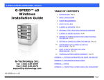
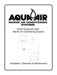
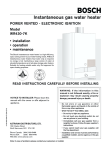
DX Built-In Air Cooled A/C Systems v INSTALLATION • OPERATION 2
Distributed By:
P.O. Box 430
Milford, VA 22514
Phone (804) 633-9454
FAX (804) 633-5499
DIRECT EXPANSION SYSTEMS
Dometic Corporation
2000 N. Andrews Ave. Ext. • Pompano Beach, FL 33069-1497 USA
Phone: 954-973-2477 • Fax: 954-979-4414
Website: www.dometic.com/marine • Email: [email protected]
Revised: 20140404
L-0261
For LP-10A
WARNING
This manual contains essential safety information
concerning the safe and proper installation of Cruisair
direct expansion air conditioning systems. It is very
important that you read and understand the contents of this
manual thoroughly before attempting to install any Cruisair
equipment. If there are any statements in this manual that
you do not understand, contact the Dometic Applications
Department for assistance. Phone 954-973-2477, Fax 954979-4414 (8:00 am - 5:00 pm United States EST).
NOTICE
As of July 1, 1992, United States federal law As of July 1,
1992, United States federal law prohibits the intentional
release of refrigerant gases into the environment, including
the R-22 refrigerant used in Cruisair air conditioning systems.
Special care must be taken when installing, charging
and servicing Cruisair equipment to prevent any loss of
refrigerant.
Cruisair does not recommend the practice of using
refrigerant to purge air and moisture from the system at
installation. This formerly used practice of purging is in
violation of United States federal law.
INTRODUCTION
This manual covers installation procedures for Cruisair
direct-expansion air conditioning systems.
In addition, there are specific installation sheets for some
models which may be shipped with Cruisair air conditioning
equipment, providing additional details for specific
components.
2
Table of Contents
Chapter 1: Description of Basic Components............................................................................................4
Basic Principles...............................................................................................................................4
Cooling Unit.....................................................................................................................................4
Controls/Switches............................................................................................................................4
Condensing Unit..............................................................................................................................4
Figure 1. SA 3 Series Control..........................................................................................................4
Figure 2. SMX Series Keypad.........................................................................................................4
Chapter 2: Installation of Basic Components.............................................................................................5
Cooling Unit.....................................................................................................................................6
Control or Switch Assembly.............................................................................................................6
Condensing Unit..............................................................................................................................6
Installation Kit..................................................................................................................................7
Figure 3. Minimum Grill and Free Air...............................................................................................5
Figure 4. Diagram of Flared Joint....................................................................................................7
Figure 5. Refrigerant Line Sizes......................................................................................................8
Chapter 3: Start-Up Procedures - Final Inspection....................................................................................9
Figure 6. Wire and Breaker Size......................................................................................................9
Chapter 4: Start-Up Procedures - Initial Charging of A New System.......................................................10
Required Tools...............................................................................................................................10
Field Charging a System............................................................................................................... 11
Removing Refrigerant from a System............................................................................................ 11
Figure 7a. Charging Pressure Charts for Equipment Built in 1994 and After.................................12
Figure 7b. Charging Pressure Charts for Equipment Built Prior to 1994........................................13
Chapter 5: Start-Up Procedures - Final Check-Out and Start-Up............................................................14
Chapter 6: General Operation.................................................................................................................15
Operating Instructions - Rotary Knobs..........................................................................................15
Operating Instructions - SMX Series Controls..............................................................................16
Chapter 7: Maintenance..........................................................................................................................17
Cooling Unit and Switch Assembly................................................................................................17
Condensing Unit............................................................................................................................17
Chapter 8: System Failure Troubleshooting Guide...................................................................................18
Chapter 9: System Charging Troubleshooting Guide...............................................................................19
Chapter 10: Installation Wiring Diagrams.................................................................................................20
Index of Diagrams.........................................................................................................................20
Warning...................................................................................................................................................31
3
CHAPTER 1: Description of Basic Components
Basic Principles
SA type switch assembly has rotary knobs for
controlling the system. Figure 1 shows a typical
SA switch assembly.
The Cruisair air conditioning system consists of
three basic components and, in some cases,
several accessory parts. They are: (1) cooling
unit; (2) control or switch assembly; and (3)
condensing unit. This instruction manual will
describe and explain the function of the basic
parts of a Cruisair system and will outline the
installation, interconnection and startup of a
complete system. It also includes maintenance
and operation of Cruisair equipment in general.
The SMX series controls are advanced
microprocessor based systems, with more
than 20 user programmable functions. These
functions are described in the SMX series
owner’s manuals. Figure 2 shows an SMXII
control panel.
Cooling Unit
The cooling unit is a refrigerant to air heat
exchanger coupled to a fan or blower which is
located in the space to be cooled. A cooling unit
is sometimes referred to as an ‘evaporator’ or a
‘cooling coil’, but in this manual, we will use the
term ‘cooling unit’. The cooling unit is constructed
of a series of copper tubes held in place by
vertical aluminum fins. Inside these tubes, the
refrigerant expands to produce a chilling effect
by absorbing the heat in the air. This air is forced
through the coil by the fan or blower.
Cooling
Down
77
Set
Inside
Heating
Up
Outside
Temp
Cool
Off
Heat
Manual
Mode
Slow
Fan
Fast
Controls/Switches
There are two basic types of controls and
switches used with Cruisair systems: the SMX
series of microprocessor controls and the SA
family of rotary knob switch assemblies. The
Figure 2. SMX Series Keypad
Filename: Fig2.EPS
Illustrator
Condensing
Unit 7.0 10-28-97
Font:
.047
pt.
The condensingHelvetica,
unit consists
of the
Line weight:the
.5refrigerant
refrigerant compressor,
receiver, the refrigerant to air heat exchanger
or condenser, condenser fan or blower, the
associated electrical components, and the
system service valves.
The basic function of the condensing unit is to
compress the expanded refrigerant, flowing back
from the cooling unit to the compressor, to a high
pressure state. The compressed refrigerant then
passes through the heat exchanger (condenser
coil) where it gives up the heat which was
absorbed in the cooling coil. It is then condensed
to a liquid state as it flows to the liquid receiver
and the process of flow back to the cooling unit
is repeated.
Figure 1. SA 3 Series Control
4
CHAPTER 2: Installation Of Basic Components
Centrifugal or blower type cooling units,
model number prefixes EBS, EBO, EHBO, EBL
or EHBL, should be mounted low, near the
return air grill, and the discharge air ducted to
the discharge grill mounted at a high level.
The following instructions should be followed,
in their proper sequence, when installing
Cruisair equipment. Read and understand the
instructions in this manual before proceeding.
Cooling Unit
In all installations, the cooling unit must be
installed so the air discharge grill is installed as
high as possible, (minimum three feet above the
floor level). The cooling unit must be installed
with the condensate drip pan positioned at the
bottom of the unit so the water dripping from the
evaporator coil collects in it before discharging
to a suitable drain outside. The cooling unit drain
must be installed so the drain tube makes an
immediate 1” drop after leaving the drain fitting.
The cooling unit must be installed so there
is an adequate path for the air to re-circulate
freely into the unit from the space being cooled.
It is important that the cross sectional area of all
discharge grills be at least equal to the coil face
area of the discharge of the cooling unit involved.
An exception is the centrifugal blower type
cooling unit.
The cross sectional area refers to the ‘free air’
area of a discharge air grill rather than the total
area as determined by the overall measurement
of the grill itself. For instance, if a grill is made of
expanded metal, perhaps only 50% of the area
is open for the passage of air. The metal web
itself will block air from passing through the other
50%. In such cases, the total area of the grill must
be doubled to achieve the required open area.
Observe this carefully when selecting a grill.
With discharge air grills located high, return
air grills should be located as close to the floor
as possible to provide the best pattern of air
flow. Avoid locating the return air grill in close
proximity to the discharge grill since the resulting
short circuiting effect of the air flow will impair
the effectiveness of the system.
Cooling units with model number prefixes
EFB, EBH, or EFL should be mounted as high
as possible, directly behind the discharge grills.
The return air grills used should be the
type which have removable filters so they
Minimum Grill And Free Air Area
EVAPORATOR
DUCT
GRILL AREA
FREE AIR AREA
Type
BTU’s
Size In.
Return (Sq. In.) Supply
Return (70%) (Sq. In.) Supply (60%)
EBL
EBO
EBS
EFB
EBH
EFL
16,000
4,000
7,000
10,000
14,000
16,000
14,000
16,000
10,000
14,000
16,000
14,000
16,000
1,000
14,000
16,000
2 @ 5
4
5
6
7
7
7
7
NA
NA
NA
NA
NA
NA
NA
NA
144
64
72
100
144
144
144
144
100
144
144
144
144
40
128
128
Figure 3. Minimum Grill and Free Air
5
2 @ 49
32
49
60
80
80
80
80
100
144
144
144
144
40
128
128
101
45
51
70
101
101
101
101
70
101
101
101
101
28
90
90
2 @30
19
30
36
48
48
48
48
60
87
87
87
87
24
77
77
Condensing Unit
can be removed and cleaned easily. The filter
material should be a type which will not cause
a significant inlet air flow pressure drop. For
all discharge air applications, wood or plastic
frames are recommended. Aluminum frame grills
will become cold and may produce secondary
condensation that will drip from the grill frame.
Cruisair condensing units are designed to
be installed in a compartment ventilated to
the outside. Air entry and exit openings to the
exterior should be protected by rain proof louvers
or grills. Space should be provided on all sides
of the unit to allow air to enter it for cooling
the condenser. All refrigeration components
are hermetically sealed and all electrical
components are spark proof for maximum safety.
Make sure the wood base is positioned at the
bottom of the unit in a horizontal plane. Fasten
the condensing unit wood base securely and
in such a way that the unit can be removed for
service if necessary.
See Figure 3 to determine the minimum grill
and free air areas for each model cooling unit.
Control or Switch Assembly
The control or switch assembly is supplied as
a separate item. The rotary switch assembly has
three knobs and the plate is printed either for
horizontal or vertical installation. It is designed
to be mounted in an opening cut on the job and
is fastened from the front with four screws. The
wiring from the switch assembly terminates
in a color coded terminal strip that should be
securely mounted in a suitable place. Electrical
connections for all systems are typically the
same.
ACA Series Condensing Units
Return Air
Operation of the SA type controls is covered
in Chapter 6.
The thermostat in the switch assembly has
a 10 foot capillary tube leading from it to the
temperature sensing bulb. This bulb must be
located in the system’s return air stream so that
the bulb is exposed only to the air returning from
the space being cooled.
The SMX control system uses a Temperature
Sensing Element (TSE) to control the operation
of the system. Like the thermostat bulb on the
SA type control, this TSE must be installed in
the return air path of the conditioned air. These
sensors are available in various lengths from 10
to 80 feet.
Operation of the SMX type controls is covered
in the SMX Series Control Systems User’s
Guide, L-634.
6
Minimum Grill Area
240 sq. in.
Free Air (70%)
168 sq. in.
Installation Kit
1. Copper Tubing
When installing the two connecting copper tubes
between the cooling unit and the condensing unit,
there are several important factors to consider.
First, the tubing can be run in lengths up to 50 feet.
It can run uphill, downhill, or sloping, as required
and can have as many bends as necessary. (Avoid
sharp bends and do not use soldered elbows.) Both
the suction and discharge lines should be insulated
individually to prevent moisture from forming on the
tube and for vibration protection. Also insulate the
connecting flare nut joints carefully to prevent dripping of moisture from these joints.
Figure 4. Diagram of Flared Joint
Caution • • • • • • • • • • • • • •
Always use refrigeration grade, seamless,
soft copper tubing. Never use neoprene,
rubber or any other type hose not designed specifically for use with R-22 and
approved by Cruisair. The refrigerant used
in Cruisair systems is monochlorodifluoromethane or R-22. This gas is compatible
with very few tube compositions with
copper being the most frequently used.
(Engine driven systems use a different
type refrigerant so therefore can use a
neoprene refrigerant lines.) The copper
tubing is connected to the cooling unit
and condensing unit with flare joints.
Flares of exceptional quality are essential
to prevent refrigerant leaks. Flares must
be of the 45°, single flare type. Do not use
a double flare. The flare should be large
enough in diameter to fill the flare nut
completely. See Figure 4.
Only the long stem forged flare nuts, such as
those that are supplied with Cruisair equipment,
are strong enough for mobile duty. Do not use long
stem machined flare nuts. Flare nuts should be
tightened until the nut ceases to offer resistance to
tightening. This is the point where the flared portion
of the copper tubing is beginning to flow or mash
under the force of the nut being tightened. After
the tubing is insulated and in place, secure it with
clamps. For proper line sizes, see Figure 5.
2. Wire Harness
SA Series Controls
The wire harness connects the condensing unit
to the main switch assembly terminal strip. The
harness or cable should include six conductors.
Normally the wire harness is run along with the
connecting copper tubing but this is not necessary.
SMX Series Controls
An interconnect cable (CX) is available in various
lengths from 10 to 80 feet. The cable includes a
plug on each end for ease of installation. The SMX
series also uses an electronic temperature sensor
which comes in various lengths and it too plugs in.
7
Air Conditioning System
with (1) Cooling Unit
& (1) Condensing Unit
Air Conditioning System
with (2) Cooling Units
& (1) Condensing Unit
Cooling Unit Line Sizes
Suction Lines
Unit Cap
14000 BTU -
16000 BTU -
Line Size
1/2”
1/2”
Unit Cap
4000 BTU -
7000 BTU -
10000 BTU -
Discharge Lines
14000 BTU -
16000 BTU -
1/4”
1/4”
Suction Discharge
3/8”
3/8”
3/8”
Condensing Unit Line Sizes
14000 BTU -
1/2”
Discharge Tee
1/4” X 1/4” X 1/4”
Suction Line
Suction Tee
3/8” X 3/8” X 1/2”
Notes:
Discharge Line
1/4”
1/4”
1/4”
1) Insulate entire length of both
refrigerant lines with closed
cell foam or equivalent
2) All tubing should be seamless
refrigeration grade copper
3) Tee’s (where applicable)
should be within 2-3 ft. of
condensing unit
Figure 5. Refrigerant Line Sizes.
8
1/4”
CHAPTER 3: Start Up Procedures - Final Inspection
The following is a list of items to be checked
before any Cruisair system is started. Be sure
that the:
14,000 BTU/hr Condensing Unit
Voltage
Wire size
Breaker size
p Cooling unit is bolted securely in place.
p Cooling unit return air cross sectional
open area is equal to the face area of the unit
evaporator coil as a minimum
115
10
30
230
12
20
Figure 6. Wire and Breaker Size
p Power line from the vehicle’s panel is
connected securely to the condensing unit
terminal strip. See wiring diagram. Be sure the
proper size circuit breaker of the time delay type
is installed. See Figure 6 for proper wire and
breaker sizes.
p Return air to the cooling unit should pass
through a filter and should come only from the
space being cooled.
p Switch assembly terminal strips are securely
mounted in a dry place, safely out of reach, and
covered.
p The refrigerant lines between the cooling unit
and condensing unit are insulated completely.
p Thermostat temperature sensing bulb or
temperature sensing element (TSE) is installed
in the cooling unit return air stream. NOTE:
These should not be touching metal parts of the
cooling unit which may become cold.
p Copper tubes and wire harness are secured
throughout their length.
p Condensing unit is securely mounted.
p Cooling unit condensate drain is in place and
working properly. Test by pouring two quarts of
water rapidly into the cooling unit drip pan.
p Flare joints at the condensing unit are tight
and insulated, after testing for leaks.
p Cooling unit wires are connected securely to
the condensing unit terminal strip.
p Flare nut joints at the cooling unit are tight.
p Flare nut joints at the cooling unit are
insulated to prevent dripping. Insulate after
testing for leaks.
p Wire harness to the condensing unit is
securely connected to the switch assembly
terminal strip.
9
CHAPTER 4: Start Up Procedures - Initial Charging Of A New System
pressure gauge hose, equipped with self
closing fittings to the red capped port. At
this point do not connect the high pressure
charging hose to anything.
4. Close all gauge manifold valves.
5.Energize the vacuum pump and open manifold
valves for the vacuum pump, the refrigerant
container, and the red capped access port low
pressure test gauge).
6.As the pump operates, you will see the low
pressure test gauge fall to a vacuum. When he
vacuum reaches 28 in. HG, close the vacuum
pump valve and turn the vacuum pump off.
Leave the system for 15 minutes and then
observe the gauge. If any vacuum is lost, a
leak is indicated. Find the source of the leak
and correct. Return to step #3 above and
re-evacuate the system. Continue until the
system will hold the vacuum.
7.Open the vacuum pump valve and leave the
vacuum pump operating for at least 6 hours
or until a vacuum of at least 29 in. HG is
achieved. Close the vacuum pump valve and
turn the vacuum pump off. Wait one hour. If
no vacuum is lost, proceed with charging. If
any vacuum is lost, a leak is indicated. Find
the source of the leak and correct. Return to
step #3 above and re-evacuate the system.
Continue until the system will hold the vacuum.
8.Open the refrigerant container valve slowly
and allow gas to enter the system until the
gauge rises to zero. You have now filled the
evacuated lines and cooling/heating unit with
refrigerant to a gauge pressure of zero. Close
the refrigerant container valve.
9.Remove the low pressure gauge hose from
the red capped port. Replace and tighten the
red cap.
10. Remove both condensing unit base valve
stem caps. Open both base valves fully by
turning the valve seems fully counterclock
wise. This will allow the refrigerant in the
condensing unit to enter the system. Replace
and tighten the valve stem caps.
Warning • • • • • • •
Federal law prohibits the intentional
release of refrigerant gas into the
environment and requires that you use
EPA approved refrigerant handling
equipment and procedures to prevent any
refrigerant gas from escaping into the air.
The following instructions should be followed in
evacuating and charging a Cruisair remote condensing unit system with R-22.
There are three refrigerant circuit components
in a Cruisair remote condensing unit system: the
condensing unit, the cooling/heating unit and
the copper refrigerant lines. The condensing
unit is shipped from the factory charged with
approximately the amount of refrigerant needed for
the whole system. The cooling unit is pressurized
with dry nitrogen and the copper tubing contains air.
The procedure will be to evacuate the nitrogen
and air from the cooling unit and the copper tubing,
then release the refrigerant from the condensing
into the entire system. To facilitate this procedure,
there is a special port with a red cap located on the
right hand base valve of the condensing unit.
Required Tools
•Refrigerant 22 container (typically the
disposable type container color coded green
for R-22)
• Four valve gauge manifold with self closing
fittings on the charging hoses
• Vacuum pump
• Base valve wrench and hand tools
• Accurate thermometer
Proceed as Follows
1. Make sure all flare joints are well made and
tight.
2.Do not touch the condensing unit base valve
stem covers or service port caps. Remove the
red port cap on the right hand base valve.
3.Connect the vacuum pump hose to the
vacuum pump. Connect the refrigerant supply
line to the refrigerant container (make sure
the container valve is OFF). Connect the low
At this point, the system is basically charged and
ready for final gas charge adjustment.
10
Field Charging A System*
6.Start the unit and observe the system
pressures. Use the Cruisair charging pressure
charts, Figure 7a or 7b to determine the
proper pressures. These charts are to be
used as a guide to setting pressures. They
are not designed to give exact pressure
settings. There are conditions that may
cause pressures to vary. Head pressures
may vary ± 10%. Suction Pressure settings
are more critical (± 5%) for functioning of the
system. Through the gauge manifold, adjust
the gas charge to obtain the proper system
pressures.
To field charge a new system which has
been evacuated and initially charged or an older
system which shows signs of needing a gas
charge, proceed as follows:
Required Tools
• Same as initial charge
Proceed As Follows:
1.Remove both base valve stem caps and
confirm valve stems are in the back seated or
counterclockwise position.
2.Remove the service port caps from both
base valves. No gas should escape. If it
does, retighten the cap and call Marine
Development Corp. for assistance.
Example for reading pressure charts:
Outside air temperature = 95° F.
Inside air (return air) = 70° F.
3. Close all gauge manifold valves.
4.Attach the gauge manifold hoses to the gauge
ports (high pressure on the right and low
pressure on the left). Connect the refrigerant
hose to the refrigerant container.
Head Pressure
230 psig
Suction Pressure
70 psig
7.To remove the gauge manifold, backseat the base valves by turning the stems
counterclockwise. Tighten the stem packing
gland nuts. Replace and tighten the stem caps.
Remove the gauge hoses. Replace and tighten
the port caps.
5.Open both base valves to the test position by
rotating the stems one turn clockwise.
*It is recommended that the charging be
done in the cooling cycle for two reasons:
Removing Refrigerant From A System
When adjusting the charge in the refrigerant
system, you may have to remove refrigerant. It is
a violation of Federal law to vent refrigerant to the
atmosphere and it is necessary that you capture
any refrigerant that is removed from the system.
There are two methods of doing this.
1. F
ollowing instructions, standard
refrigeration gauges are connected for the
cooling cycle.
2. In the heating cycle, the same pressure
may be observed at two different charge
levels, and an overcharge may result.
Use an approved recovery unit and refillable
refrigerant container.
Allow refrigerant to escape from the high
pressure side into a refillable refrigerant container.
Once the system is properly charged, you are
ready for final inspection and check-out.
11
Cooling Cycle
Equipment Built in 1994 and After
IMPORTANT
To determine desired pressures, exact inside and outside temperatures must be measured.
80
75
70
65
Indoor
Temp.
90
(F°)
60
80
Suction
Pressure
(PSIG)
55
70
50
60
65
70
75
80
85
90
95
100
105
110
115
120
45
Outdoor Air (F°)
400
375
350
325
300
Indoor
Temp.
(F°)
275
250
225
90
80
70
60
200
65
70
75
80
85
90
95
100
Outdoor Air (F°)
Figure 7a. Charging Pressure Charts
12
105
110
115
120
175
Head
Pressure
(PSIG)
Cooling Cycle
Equipment Built Prior To 1994
IMPORTANT
To determine desired pressures, exact inside and outside temperatures must be measured.
120
110
100
90
p.
Indoor
Temp.
(F°)
em
ir T
A
0°
9
°
80
90
Air
Te
70
.
mp
e
ir T
7
80
80
.
mp
A
0°
60
p.
em
ir T
50
A
0°
6
70
40
50
60
Suction Pressure
(PSIG)
70
80
90
Outdoor Air (F°)
400
90°
Indoor
Temp.
(F°)
90
Air
80
Te
.
p
em
ir T
80°
A
70°
A
60°
350
.
mp
.
p
em
ir T
Air
.
mp
Te
300
250
200
150
100
70
50
60
40
50
60
70
80
Outdoor Air (F°)
Figure 7b. Charging Pressure Charts
13
90
Head Pressure
(PSIG)
CHAPTER 5: Start Up Procedures - Final Check-Out and Start-Up
difference the two readings should be 15 to
20 degrees Fahrenheit. Note that humidity
will diminish the temperature differential and
cooling capacity. Cooling capacity diminishes
in very warm outside, air (above 95° F / 35° C),
and heating capacity decreases when outside
air temperature drops below 40° F / 4° C.
pActuate the circuit breaker for the air
conditioning.
p A
ctuate the air conditioning system at the
control panel/switch assembly, following the
directions in the Cruisair owner’s manual.
p A
llow unit to run for 15 minutes, then check the
temperature differential by placing an accurate
thermometer in front of the discharge grill. After
recording the temperature, place the same
thermometer in front of the return air grill. The
If everything checks okay, the system is ready to
go.
14
CHAPTER 6: General Operation
Operating Instructions:
Rotary Knobs
Setting Desired Temperature
To set the thermostat, allow the unit to operate
until the living area is cooled or heated to the
desired temperature. At this point, turn the thermostat (WARMER/COOLER) knob slowly toward
the center position until you hear it “click” once.
The thermostat is now set to maintain the desired
temperature.
Before attempting to start the Cruisair system
equipped with the rotary knob control, verify the
OFF/FAN/RUN control is in the off position and
proceed as noted below:
Power On
Setting the Fan Speed
Turn on the circuit breaker on your vehicle’s electrical panel designated for the air conditioner.
Use the center knob to set the fan speed to the
desired air flow by rotating it between the LOW and
HIGH position.
Set the Thermostat
Turn the WARMER/COOLER knob to the desired
mode of operating. (cooling or heating)
Turning the System Off
To turn the system off, rotate the top knob to the
OFF position. The other knobs can be left where
they are set for later operation.
Set the Fan Speed
Rotate the fan speed knob to the full clockwise or
the High speed position.
Note • • • • • • • • • • • • • • • • •
Starting the Fan
If you turn the system off or if you wish to
switch between cooling and heating, wait
three minutes to allow the unit’s internal
pressures to equalize before attempting to
restart the compressor.
Move the top control knob to the FAN position to
energize the blower. Verify that the fan did start
moving air.
Starting the Compressor
Move the top control knob to the RUN position.
The compressor will start and the unit will begin to
cool or heat, depending on which mode of operation you have selected and what the current inside
temperature is.
15
Operating Instructions:
SMX Series Controls
Selecting the Cooling or Heating
Mode
Select the cooling or heating mode by
pressing either the COOL or HEAT key. The
small LED above the key will light up to show
whether the system is in the cooling or heating
mode. For automatic changeover between
cooling and heating, press the COOL and HEAT
keys simultaneously, and both LED’s will light.
The “Heating” or “Cooling” LED on either side of
the TEMP display will light when the compressor
is running to indicate the operating status of the
system.
Several different models of SMX Series controls
are available. Operation procedures are similar
for all of them. Any differences are noted below:
Power On
Turn on the circuit breaker on your vehicle’s
electrical panel designated for the air conditioner.
The system will automatically begin operating
with settings that were in effect when the power
was interrupted. If the system had been shut
down using the OFF key, it will be necessary to
select the cooling or heating mode to restart the
system.
Adjusting Fan Speed
Display the current setpoint by pressing the
SET key. The LED above the key will light and
setpoint will be displayed in degrees Fahrenheit
or Celsius. The setpoint is the temperature you
wish to maintain. It is adjusted by pressing the
UP or DOWN key adjacent to the SET key.
Select manual or automatic fan speed by
pressing the FAN key. This switch toggles back
and forth between manual and automatic. The
line of small LED’s below the FAN key will give
you a visual indication of the relative fan speed.
In the manual mode, you can control fan speed
by using the SLOW and FAST keys. When in the
automatic mode, fan speed is adjusted by the
computer, based on the differential between the
setpoint and actual inside temperature.
Displaying Interior Temperature
Adjusting Brightness
Selecting the Desired Temperature
To display the current interior temperature,
press the TEMP key once. The display will show
the inside temperature.
The brightness of the display and status
LED’s can be adjusted on the SMXII from the
keyboard by pressing the SET key a second
or third time. The SMX Online is automatically
adjusted to constantly provide easy reading of
the display both during the day and at night.
(SMXII)
For an alternating display of both inside
temperature and setpoint, press the TEMP key
again. Return to inside temperature display by
pressing TEMP again.
Turning the System Off
To turn the system off, press the OFF key. Note
that the data display remains on until you turn
off the circuit breaker on your vehicle’s electrical
panel.
(SMX and SMX OnLine)
To display the outside temperature, if your
system is equipped with an outside thermistor,
press the TEMP key again. The small LED
marked “Outside” will light and the display will
show outside temperature. Press the TEMP
key a third time and you will see an alternating
display of setpoint, inside temperature
and outside temperature. Return to inside
temperature by pressing TEMP again.
Advanced Programming
Refer to the SMX series user’s guide for
additional details on Cruisair’s computer-based
control systems.
16
CHAPTER 7: Maintenance
Cooling Unit and Switch Assembly
Warning • • • • • • • • • • • • •
Switch contacts are self-cleaning and require
no maintenance. At the beginning of each trip,
check the cooling unit condensate drains for
total or partial obstruction by pouring two quarts
of water rapidly into the condensate drip tray.
It should drain completely within 30 seconds.
When the cooling unit was installed initially, a
filter should have been installed in the return
air path. Locate this filter and clean it if a visible
buildup of lint has collected. If filters were
installed, they are usually located behind the
return air grills.
In conjunction with the operation of
air conditioning equipment, there are
oversights which can lead to HAZARDOUS
conditions which could result in FATAL
accidents.
Observe The Following:
Every Cruisair component must be
electrically grounded using the grounding
points provided. Failure to complete
electrical grounding COULD result in
severe electrical shock and DEATH.
Condensing Unit
The condensing unit requires minimal
maintenance. The refrigeration circuit is
hermetically sealed and is charged with oil
at the factory. No oil should be added. The
refrigerant (R-22) gas in the system is adequate
for the life of the unit. The gas charge should
not be changed or altered except in the event
the unit was charged improperly in the original
installation or unless a leak occurs which allows
gas to escape from the system. The condenser
coil should be inspected periodically for possible
buildup of dirt and/or obstructions. Fan motors
on the condensing units should be oiled
periodically.
Carbon monoxide poisoning is a possibility
which should be carefully considered.
NEVER close a vehicle and operate an
air conditioning system while any engine
or generator is operating ON or NEAR the
vehicle. Carbon monoxide is an odorless
and deadly poisonous gas contained in the
exhaust of any engine. When in audible
range of any operating engine, NEVER
CLOSE A VEHICLE AND REMAIN
INSIDE.
17
CHAPTER 8: System Failure Troubleshooting Guide
Trouble
Probable Cause
Symptoms
Remedy
Compressor fails to start
Power source failure
No current at power source
Check for tripped
circuit breaker
Faulty switch assembly
No current at condensing
Check for faulty
unit terminal strip
switch
Low voltage
Compressor tries to start &
Correct power
then cuts off
source
Faulty high pressure
Voltage to switch but no
Replace high switch
voltage between the switch
pressure switch
and compressor
Faulty compressor
Unit draws locked rotor amp.
Replace compressor
(locked rotor amp found on
data plate)
Compressor cycles every
Low voltage
Compressor’s thermal
Correct power source
15 to 30 seconds
overload opens
Incorrect refrigerant
Excessive head pressure
See refrigerant
charge
charge instructions
Restricted condenser Excessive head pressure.
Correct condenser
air flow
High pressure switch opens
air flow
High pressure switch Switch opens before 425 Replace high incorrectly set
psig head pressure
pressure switch
System not cooling
Switch assembly not set
Ventilation operation only
Set switch and
properly or thermostat
thermostat at correct satisfied
selection
No or restricted air flow
Compressor cycles quickly
Check for restricted condenser air flow
System low on refrigerant
Compressor suction line
Check refrigerant warm
charge
Thermostat satisfied
Compressor runs for short
Reset thermostat to time and then cycles off
desired level. Calibrate
if necessary
Iced cooling unit
Restricted air flow
Restricted discharge air flow
Low refrigerant charge
Compressor suction line
warm
Blower or fan motor Power source failure
No current at power system
inoperative
Low voltage
Hot motor. Motor thermal/electric protector open
Faulty switch assembly
No power to motor
Cooling unit throwing Blocked or restricted Excessive water out of
water out of
condensate drain
discharge grill
discharge grill
18
Clean return air filter & check for air flow restrictions
Check refrigerant charge
Check for tripped circuit breaker
Check power
source
Replace faulty switch
Check for condensate drain restrictions
CHAPTER 9: System Charging Troubleshooting Guide
Pressures
Suction/Discharge
Normal
Normal Symptoms
Possible Cause
Suction line sweating w/droplets up to compressor Proper charged system
Compressor warm on top & hot on bottom
Temp differential across cooling coil is 16-20° F
Low
Low
Suction line cool, not sweating
Low on charge
Compressor hot on top and bottom
Cooling coil temp. differential low
System drawing very low amps
Suction line has small beads of moisture
No load due to low Compressor is cool to cold & may be sweating
evaporator temp. Normal to high cooling coil temp. differential
Low
High
Suction line cool to cold with frost or no sweat
Kinked refrigerant line May have frost line at point of blockage
Blockage in refrigerant line
Compressor hot
Compressor may draw high amps
Cooling coil temp. differential low
Suction line cool to cold with frost or no sweat
Low charge/no condensing
Cooling coil temp. differential low
Compressor hot
Compressor may draw high amps
Suction line cool to cold with frost or no sweat
Non-condensable in refrig-
May have frost line at point of blockage
erant (air or moisture)
Compressor is hot
Compressor may draws high amps
Cooling coil temp. differential low
High
Low
Suction line ambient to cool
Defective component Compressor is warm
faulty comp. valves or
Compressor draws low amps
reversing valve
Cooling coil temp. differential is low
System exhibits marginal to zero performance
Rapid rise in suction pressure & moderate rise
in head pressure when condenser air is blocked
High
High
Suction line cool to cold with thin film of moisture Over charged system
Compressor cold and sweaty
Cooling coil temp. differential is low
System pressures may be anywhere on gauges
High pressure switch trips
Compressor draws high amps
High
High
Suction line cool to ambient
No condensing of
Compressor warm
refrigerant
Cooling coil temp. differential low
Compressor may trip circuit breaker
Suction line cool to ambient
High load caused by hot
Compressor warm
living area temp. or high
Cooling coil temp. differential high
outside air
19
Remedy
N/A
Low charge - frosty
suction line
Very low charge suction line feels ambient
to cool
Cooling cycle - low air
flow or room temp.
Heating cycle - low
condenser air flow or
outside air temp.
Check for kinked or
pinched lines - remove
any moisture or trash
in refrigerant circuit.
Verify base valves are
open.
Cooling mode - check
outside air flow
Heating mode - check
inside air flow
System must be evacuated and recharged
Determine faulty
component and replace
Remove charge until
suction pressure is
about 50 psig - allow
system to run until
comp. gets warm then recharge slowly
Cooling mode - check
condenser air flow
Heating mode - check
inside air flow
Condition should
improve as room temp.
is lowered.
Should not trip breaker
CHAPTER 10: Installation Wiring Diagrams
Index of Diagrams
• Cooling Only Systems Built and Installed Through 1989
For: Condensing Units: ACA-14 Series
Controls: SA1 Series Switch Assembly............................................................................................... 21
• SKB-208 Cooling Only Systems Built and Installed From 1989 Through June 1996
For: Condensing Units: ACA-14U & ACA-14BU
Controls: SA1 Series Switch Assembly............................................................................................... 22
• SKB-208A Cooling Only Systems Built and Installed From 1989 Through Current Production
For: Condensing Units: ACA-14U, ACA-14BU, ACA-14BS, & ACA-14HBS
Controls: SA1 Series Switch Assembly............................................................................................... 23
• SKB-690 Cooling w/Auxiliary Electric Heating Systems
Built and Installed From 1996 Through Current Production
For: Condensing Units: ACA-14U, ACA-14BU, ACA-14BS, & ACA-14HBS
Cooling Units: EHBO & EHBL Series w/Built in Heaters
Controls: SA13 Series Switch Assembly............................................................................................. 24
• No. 825-06 Reverse Cycle Heat Pump Systems
Built and Installed From 1990 Through Current Production
For: Condensing Units: ACAH-14B & ACAH-14BU
Controls: SA3 Series Switch Assembly............................................................................................... 25
• No. 825-06A Reverse Cycle Heat Pump Systems
Built and Installed From 1991 Through Current Production
For: Condensing Units: ACH-14B, ACH-14BU, & ACH-14HB
Controls: SA3 Series Switch Assembly............................................................................................... 26
• No. 825-15 Reverse Cycle Heat Pump Systems
Built and Installed From 1991 Through Current Production
For: Condensing Units: ACH-14B, ACH-14BU, & ACH-14HB
Controls: SMXII Series Micro-processor............................................................................................. 27
• No. 082550 Reverse Cycle Heat Pump w/Auxiliary Electric Heating Systems
Built and Installed From June 1997 Through Current Production
For: Condensing Units: ACH-14B, ACH-14BU & ACH-14HB
Cooling Units: EHBO & EHBL Series w/Built in Heaters
Controls: SMX OnLine Series............................................................................................................. 28
• No. 082551 Reverse Cycle Heat Pump w/Auxiliary Electric Heating Systems
Built and Installed From June 1997 Through Current Production
For: Condensing Units: ACH-14B, ACH-14BU & ACH-14HB
Cooling Units: EBS & EFL Series w/External Electric Heaters and HMDL-2,
HMBL-2, & HMHL-2 Series Heat Modules
Controls: SMX OnLine Series............................................................................................................. 29
20
Cooling Only Systems Built and Installed Through 1989
SA1-ZB10
Switch
Assembly
To AC
Power
Panel
115V
60Hz-1Ø
Condensing Unit
ACA-14 Series
Ground Lug
Cooling Unit
Condensate
Drain
Typical Wiring Diagram: (1) Condensing Unit & (1) Cooling Unit
To AC
Power
Panel
115V
60Hz-1Ø
SA1-ZB10
Switch
Assembly
Cooling Unit
Condensing Unit
ACA-14 Series
Cooling Unit
Switch
Assembly
Typical Wiring Diagram: (1) Condensing Unit & (2) Cooling Units
21
22
For Condensing Units:
ACA-14U, ACA-14BU
Controls: SA1 Series Switch Assembly
SKB-208 Cooling Only Systems Built and Installed From 1989 - June 1996
23
SKB-208A
For Condensing Units: ACA-14U, ACA-14BU, ACA-14BS, & ACA-14HBS
Controls: SA1 Series Switch Assembly
Cooling Only Systems Built and Installed From 1989 - Current Production
24
Cooling Units: EHBO & EHBL Series w/Built in Heaters
Controls: SA13 Series Switch Assembly
For Condensing Units: ACA-14U, ACA-14BU, ACA-14BS, & ACA-14HBS
SKB-690 Cooling w/Auxiliary Electric Heating Systems
Built and Installed From 1996 - Current Production
25
P-485
Controls: SA3 Series Switch Assembly
For Condensing Units: ACAH-14B & ACAH-14BU
No. 825-06 Reverse Cycle Heat Pump Systems
Built and Installed From 1990 - Current Production
26
Controls: SA3 Series Switch Assembly
For: Condensing Units: ACH-14B, ACH-14BU, & ACH-14HB
**Wiring Changes Required** When System is Controlled by SA3-Z Series
No. 825-06A Reverse Cycle Heat Pump Systems
Built and Installed From 1991 - Current Production
27
P-572
Controls: SMXII Series Micro-processor
For Condensing Units: ACH-14B, ACH-14BU, & ACH-14HB
No. 825-15 Reverse Cycle Heat Pump Systems
Built and Installed From 1991 - Current Production
28
P-782
For Condensing Units: ACH-14B, ACH-14BU& ACH-14HB
Cooling Units: EHBO & EHBL Series w/Built in Heaters
Controls: SMX OnLine Series
No. 082550 Reverse Cycle Heat Pump w/Auxiliary Electric Heating Systems
Built and Installed From June 1997 - Current Production
29
P-783
No. 082551
For Condensing Units:
ACH-14B, ACH-14BU& ACH-14HB
Cooling Units:
EBS & EFL Series w/External Electric Heaters
and HMDL-2, HMBL-2, & HMHL-2 Series Heat Modules
Controls: SMX OnLine Series
Reverse Cycle Heat Pump w/Auxiliary Electric Heating Systems
Built and Installed From June 1997 - Current Production
Notes
30
WARNING
Dometic Corp., manufacturer of Cruisair, Grunert, Marine Air and Sentry
Products, makes the following safety warnings concerning the application,
installation, use and care of its products. Although these warnings are extensive,
there may be specific hazards which may arise out of circumstances which we
have not outlined herein. Use this as a guide for developing an awareness of
potential hazards of all kinds. Such an awareness will be a key factor in assuring
your SAFETY and comfort.
occupants or bystanders, or (2) cause a suction or low pressure in an area where
hydrogen gas from batteries, raw fuel vapor from fuel tanks, carbon monoxide from
operating propulsion engines, power generators or heaters, methane gas from
sewage holding tanks, or any other dangerous gas or vapor could exist. If an air
handling unit is installed in such a manner that allows potentially lethal gases or
vapors to be discharged by the air handling unit into the living space, this could
result in loss of life.
ELECTRICITY - Many Dometic products operate on 115, 230 or 440 volt AC
power. Such voltages can be LETHAL; therefore, the chassis, cabinets, bases,
etc., on all components must be grounded together and connected to the vessel’s
grounding system. Sparks can occur as switches, thermostats and relays open
and close in the normal operation of the equipment. Since this is the case,
ventilating blowers for the removal of hazardous fumes or vapors should be
operated at least 5 minutes before and during operation of any Dometic product
or group of Dometic products. All electrical connections must be covered and
protected so accidental contact cannot be made by persons using the equipment,
as such contact could be LETHAL.
Maximum protection against the introduction of dangerous gases or vapors into
living spaces can be obtained by providing living spaces which are sealed from
all other spaces by use of airtight bulkheads and decks, etc., and through the
introduction of clean air into the living space. Bear in mind that the advent of air
conditioning, whether it be for cooling or for heating, naturally leads to the practice
of closing a living space tightly. Never close all windows and doors unless auxiliary
ventilating systems, which introduce clean outside air into the living space, are
used. Always leave enough window and door openings to provide adequate
ventilation in the event potentially lethal gases or fumes should escape from any
source.
ELECTROLYSIS - Electrical leakage of any component can cause electrolytic
deterioration (electrolysis) of thru-hull components which could result in leakage
serious enough to sink a vessel which could result in loss of life. All Dometic’s
components must be kept clean and dry and checked periodically for electrical
leakage. If any electrical leakage is detected, the component should be replaced
or the fault causing the leakage corrected before the component is put back into
service.
CONDENSATE - All cooling units produce water condensate when operating on
the cooling cycle. This water must be drained from the cooling unit overboard.
If condensate is allowed to drip on a wooden structure, rotting or decay and
structural failure may occur which could result in loss of life. If condensate
is allowed to drip on electrical components, deterioration of the electrical
components could result in hazardous conditions. When an air conditioning system
is in operation, condensate drains may be subjected to negative pressure. Always
locate condensate drains as far as possible from points where engine waste and
other dangerous gases are exhausted so no such dangerous gases can be drawn
into the condensate drains.
GAS - CRUISAIR, MARINE AIR and GRUNERT components utilize R134a
refrigerant, tetrafluoro-ethane or R404A, R125/R143a/R134 (44%/52%/47%)
which are non-toxic, non-flammable gases; however, these gases contain no
oxygen and will not support life. Refrigerant gas tends to settle in the lowest
areas of the compartment. If you experience a leak, evacuate all personnel, and
ventilate area. Do not allow open flames in the area of leaks because refrigerant
gas, when burned, decomposes into other potentially LETHAL gases. Refrigerant
components operate at high pressure and no servicing should be attempted
without gloves, long-sleeved clothing and eye protection. Liquid refrigerant gas
can cause severe frost burns to the skin and eyes.
Warning
Never sleep in a closed area on a boat when any equipment, which functions
as a result of the combustion of a volatile fuel, is in operation (such as engines,
generators, power plants, or oil-fired heaters, etc.) At any time, the exhaust system
of such devices could fail, resulting in a build-up of LETHAL gases within the
closed area.
VENTILATION - To cool or heat air, CRUISAIR, MARINE AIR and GRUNERT
components are designed to move air through a heat exchanger by a blower or
propeller fan. This design necessarily produces a suction on one side of the air
handling component and a pressure on the other side. Air handling components
must be installed so that the suction-pressure action does not: (1) pressurize
an area to the extent that structural failure occurs which could cause harm to
Warning Revised: 7-6-99
31
2000 N. Andrews Ave. Ext. • Pompano Beach, FL 33069-1497 USA
Phone: 954-973-2477 • Fax: 954-979-4414
Website: www.dometic.com/marine • Email: [email protected]
L-0261