1
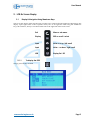
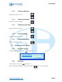
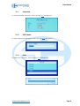
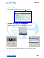
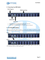
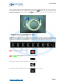
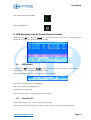
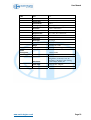
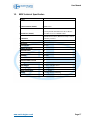
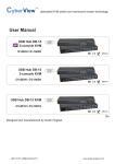
CyberView User Manual
RKP215-801
RKP217-801
RKP215-1601
RKP217-1601
2U Rackmount LCD monitor
Keyboard drawer with KVM switch
Version 2.0
20 March 2004
User Manual
Table of Contents
1.0
General............................................................................................................ 3
1.1
Unit Introduction........................................................................................... 3
1.2
Unit Photograph............................................................................................ 3
1.3
Unit Features ................................................................................................ 3
1.4
Unit Packing Contents ................................................................................... 3
1.5
Important Information & Safeguards ............................................................... 4
1.6
Preparation for Use....................................................................................... 4
2. LCD On Screen Display ......................................................................................... 5
2.1
Display & Navigation Using Membrane Keys ................................................... 5
2.2
Customizing the LCD Settings......................................................................... 6
3. Miscellaneous Sub Menu ..................................................................................... 7
4. Setting OS Refresh Rate - Microsoft Windows® ..................................................... 9
5. Connecting Your KVM Switch.............................................................................. 10
6. Cascading KVM Switches ................................................................................... 10
7. KVM Navigation Using Membrane Keys ............................................................... 11
8. KVM Navigation using On Screen Display & Hot keys ........................................... 12
8.1
OSD Password ............................................................................................ 12
8.2
Consol ON / OFF .......................................................................................... 12
8.3
To reset the KVM to default setting using the membrane keys ........................ 13
8.4
To select the previous channel .................................................................... 13
8.5
To select the next channel........................................................................... 13
8.6
To select the previous bank......................................................................... 13
8.7
To select a specific bank and channel ......................................................... 13
8.8
To Turn channel beeper on or off ................................................................. 13
8.9
To Auto scan channels ................................................................................ 13
8.10 To reset the KVM to default ROM setting....................................................... 14
8.11 To identify an active channel....................................................................... 14
8.12 To assign a channel a name designation ...................................................... 14
8.13 To find a channel by its name designation .................................................... 14
9. LCD Technical Specification ............................................................................... 15
10.
KVM Technical Specification .......................................................................... 17
11.
LCD Troubleshooting....................................................................................... 18
11.1 The LCD does not function, the PC input is operational .................................. 18
11.2 The message ‘Check Cable’ appears on the LCD............................................ 18
11.3 The message ‘No Sync’ appears on the LCD .................................................. 18
11.4 The message ‘Signal out of Range’ appears on the LCD ................................. 18
12.
KVM Troubleshooting...................................................................................... 18
12.1 The Keyboard does not work after boot up .................................................... 18
12.2 The Mouse is not detected during PC boot routine......................................... 18
13.
Warranty........................................................................................................ 19
13.1 Period & Conditions .................................................................................... 19
13.2 Manufacturers exclusions............................................................................ 19
14.
Disclaimer ..................................................................................................... 19
www.austin-hughes.co.uk
Page 2
User Manual
1.0
1.1
General
Unit Introduction
Thank you for purchasing the 2U Rackmount LCD monitor keyboard drawer with KVM switch. The
unit is a unique combined 19” rack mountable unit designed to provide access to and control of
multiple servers from a single unit. The unit offers space saving leading edge, flexible, features and
provide tangible benefits to the user while ensuring the reliability, cost efficiency and return on
hardware investment expected for today’s broadcast, enterprise and service provider networks.
1.2
Unit Photograph
1.3
Unit Features
•
•
•
•
•
•
•
•
•
1.4
15 or 17 inch TFT/LC active matrix color
Built in OSD (On Screen Display) controlled by integral membrane keys
Flexible keyboard selections, notebook type with touch pad mouse or Cherry type with
trackball mouse, available in multiple languages
Keyboard slide rails have friction stop positions to prevent accidental movement
Built in 8 or 16 port KVM switch, cascade-able to 64 / 128 ports or servers
Unique KVM integral membrane one button port selection
KVM port selection through OSD Hot key menus
Efficient cable management, the unit is supplied with 8 x 6ft screened VGA cables with
combined PS2 mouse and keyboard connectors – refer to section 5.0 of this user manual
Single external 12V 5A remote power adaptor, easy to replace and ensures only a single
power source is required to the unit , reducing the capacity of UPS outputs for KVM
switches required
Unit Packing Contents
Model Number
801
1601
RKP215 / 217 2U LCD Keyboard Drawer with KVM Unit
1
1
User Manual CD
1
1
Quick Reference Guide
1
1
AC to DC Power Adaptor
1
1
Standard 6ft 3 in 1 KVM cables (CD-6)
8
8
Rack Mount Kit
1
1
www.austin-hughes.co.uk
Page 3
User Manual
1.5
•
•
•
•
•
•
•
•
•
•
•
•
1.6
•
•
•
•
•
•
•
•
•
Important Information & Safeguards
Please read these safety instructions carefully
Keep this user manual for later reference
Disconnect the unit from the mains input power supply source before cleaning
Do not spray aerosol or liquid cleaners directly on the unit, use only a soft cloth for cleaning
Clean the LCD only with a soft anti static cloth
Avoid placing pressure on the LCD to prevent permanent damage
Rest the unit on a reliable surface when installing, a drop or fall may cause injury
Please note all cautions and warnings on the equipment
Never open the unit. Only qualified personnel should open the unit
Refer to section 10.0 of this user manual regarding recommended storage and operating
conditions for the unit
Refer to sections 11.0 and 12.0 of this user manual regarding troubleshooting of the unit
Refer to section 13.2 of this user manual regarding improper use of the unit
Preparation for Use
Carefully remove the unit from its packaging
Please check that the unit and its accessories match the packing contents in section 1.4 of this
user manual
Please read this user manual thoroughly familiarising yourself with the unit
Place the unit on a protected work surface and carefully slide open the keyboard drawer
noting the friction stops on the slides to prevent movement of the keyboard whilst in use
Carefully slide open and lift the LCD screen to a convenient viewing angle
Plug up the DC power supply, whilst noting that the green LED on the external adaptor
should now be lit
You should now be able to see the LED lights on the unit functioning you could also follow
section 2.0 to familiarise yourself with the OSD (On screen display) of the unit
After removing the DC power input, carefully install the unit into the rack, noting section
1.5 of this user manual - important information and safe guards, and plug in all connecting
hardware (ensure all connecting hardware is powered down for this stage of the install)
Further information regarding the use of this unit can be found in the following sections of
this user manual
www.austin-hughes.co.uk
Page 4
User Manual
2. LCD On Screen Display
2.1
Display & Navigation Using Membrane Keys
The On screen display built into the unit provides users with an efficient method of adjusting to the
display input signal. This section explains clearly how to navigate the OSD using the membrane
keys, shown below, that you will find on the unit to the right side of the LCD screen.
2.1.1
Exit
Menu or sub menu
Display
OSD or scroll / select
Input
Value + or up / left scroll
Input
Value – or down / right scroll
LCD
Display On / Off
To display the OSD
Simply press the key marked
www.austin-hughes.co.uk
Page 5
User Manual
2.1.2
To Select a Menu Item
Simply press the key to scroll
2.1.3
To Enter the Sub Menu
Simply press the key marked
2.1.4
To Change an Input Value
Simply use the key marked
2.1.5
To Save the setting
Simply press the key marked
2.1.6
To Exit the Main Menu
Simply use the key marked
2.2
2.2.1
Customizing the LCD Settings
Brightness / Contrast
To adjust brightness - follow steps 2.1.1 through 2.1.5
2.2.2
Auto Adjust
To auto adjust - follow steps 2.1.1 through 2.1.5
NOTE -: While the OSD Menu is NOT displayed the
www.austin-hughes.co.uk
key acts as Auto Adjust
Page 6
User Manual
2.2.3
Phase / Clock
To optimize display qualities - follow the steps 2.1.1 through 2.1.5
2.2.4
Horizontal Screen Position
To adjust horizontal screen position - follow the steps 2.1.1 through 2.1.5
2.2.5
Vertical Screen Position
To adjust horizontal screen position - follow the steps 2.1.1 through 2.1.5
2.2.6
To reset to default factory setting
To reset - follow the steps 2.1.1 through 2.1.5
3. Miscellaneous Sub Menu
To select miscellaneous sub menu - follow the steps 2.1.1 through 2.1.5
www.austin-hughes.co.uk
Page 7
User Manual
3.1.1
Information
To select information sub menu - follow the steps 2.1.1 through 2.1.5
3.1.2
OSD Timeout
To select OSD Timeout sub menu - follow the steps 2.1.1 through 2.1.5
3.1.3
Color
To select Color sub menu - follow the steps 2.1.1 through 2.1.5
www.austin-hughes.co.uk
Page 8
User Manual
3.1.4
OSD language
To select the OSD language sub menu - follow the steps 2.1.1 through 2.1.5
4. Setting OS Refresh Rate - Microsoft Windows®
On the windows desktop ‘right click’ the mouse key and then select ‘properties’
Select ‘Settings’ from the tab menu
Select ‘Monitor’ and then select a Screen refresh Rate of 75 Hertz – Press OK to save and exit
www.austin-hughes.co.uk
Page 9
User Manual
5. Connecting Your KVM Switch
12V DC Power In
KVM Channel Ports
Cascade Port
Consol Port
•
•
•
KVM Channel Port – to connect servers using 3 in 1 KVM cable
Cascade Port – to connect to another KVM switch
Consol Port – to be connected to previous bank (if exists) Cascade port
6. Cascading KVM Switches
Using 3 in 1 KVM cable connect from Bank 1’s “Cascade port” to Bank 2’s “Console port”. When
connected please press “Bank” & “Channel” button on the front of the KVM switch to reset the KVM
Bank 1
Bank 2
A maximum of 8 banks or 128 ports can be cascaded. Austin Hughes ranges of KVM switches are
fully compatible with most vendors KVM switches.
www.austin-hughes.co.uk
Page 10
User Manual
Note – the maximum recommended distance between the KVM port and the server is 15ft, use
Austin Hughes standard 3 in 1 KVM cable part number CD15 shown below. To cascade between
switches use Austin Hughes standard cable CA15 the CA 15 cable has 2 x PS2 connections at both
the ends of the cable.
7. KVM Navigation Using Membrane Keys
Membrane Keys built into the unit provide users an efficient method of changing KVM ports very
quickly and accurately. This section explains clearly how to switch and monitor the KVM ports using
the membrane keys that you will find on the CyberView unit underneath the LCD screen.
RED LED highlights ‘Active Channel’
RED & GREEN LED highlights ‘Active and On Line Channel’
Simply press this key to select a channel or port between 1-8
Simply press and hold together with a channel button to select ports 9-16
www.austin-hughes.co.uk
Page 11
User Manual
This LED box displays the Bank
Select Bank Button 1 - 8
8. KVM Navigation using On Screen Display & Hot keys
Hold down the FN key and press Scroll on your keyboard twice in succession - the OSD will be
displayed for 10 Sec; this can be prolonged to 99 Sec
8.1
OSD Password
Hold down the FN key and press Scroll on your keyboard twice in succession – the OSD will be
displayed for 10 Sec; this can be prolonged to 99 Sec
Select Change Password – the screen capture below will appear
Key in the unit default password 00000000
Enter the new password (8 digits max)
Re-Enter the new password
Dialog will now display – Changing Password Complete
8.2
Consol ON / OFF
If the Consol displays ON – any user can operate the unit
If the Consul displays OFF – the user must key in the current password to operate the unit
www.austin-hughes.co.uk
Page 12
User Manual
The Unit default setting is Consul OFF – the user must key in the current password to operate the
unit
8.3
To reset the KVM to default setting using the membrane keys
Simply press the
8.4
and channel
buttons together
To select the previous channel
Simply press the Scroll on your keyboard twice in succession followed by the
8.5
on your keyboard
To select the next channel
Simply press the Scroll on your keyboard twice in succession followed by the
on your keyboard
Note – You may hold either arrow key to scan through channels
8.6
To select the previous bank
Simply press the Scroll on your keyboard twice in succession followed by the PgUp on your
keyboard
8.7
To select a specific bank and channel
Simply press the Scroll on your keyboard twice in succession followed by the bank number and
channel number on your keyboard
Example Scroll + Scroll + bank number (1-8 Max.) + channel number (01-16 Max.)
8.8
To Turn channel beeper on or off
Simply press the Scroll on your keyboard twice in succession followed by the B on your keyboard
(default is beeper on)
8.9
To Auto scan channels
Simply press the Scroll on your keyboard twice in succession followed by the S on your keyboard
(default scan time is 10 Secs. from channel to channel) – Press any key on your keyboard to stop
scanning
www.austin-hughes.co.uk
Page 13
User Manual
8.10
To reset the KVM to default ROM setting
Simply press the Scroll on your keyboard twice in succession followed by the R on your keyboard
(note -: THIS DOES NOT RESET THE PASSWORD)
8.11
To identify an active channel
Simply look for the ☼ symbol on the on screen display next to the channel designation
8.12
To assign a channel a name designation
Simply select the KVM OSD, see section 8.0 of this user manual, use the Tab key on your keyboard
to select the default channel designation (e.g. SYSTEM 01) and press the INS key on your keyboard
to edit the channel name designation, press ENTER on your keyboard when complete
Note -: the channel name designation should not exceed 8 characters
8.13
To find a channel by its name designation
Simply press the Scroll on your keyboard twice in succession followed by the F on your keyboard,
type the channel name, see section *** of this user manual, press enter on your keyboard – the unit
will begin searching from channel 1
www.austin-hughes.co.uk
Page 14
User Manual
9. LCD Technical Specification
LCD
Video
Size
15"
Screen Area
TFT Active Matrix
Display Area
304.1mm (h) x 228.1mm (V)
Contrast Ratio
300:1
Viewing Angle
130 deg (H) z 115 deg (V) TYP
Resolution
1024 x 768 XGA
Pixel Pitch
0.297mm (H) x 0.297mm (W)
Response Time
Tr = 5ms, TF = 20ms TYP
Brightness
250 cd/m2
Panel Color
16.2M Colors
Back Light
4 Lamps
Synchronization
Horizontal 48.36-60 KHz
Range
Vertical 56-75 Hz
Input Signal
Analog RGB 0.7Vp-p
Power
Management
www.austin-hughes.co.uk
VESA DPMS
Power
Micro on/off switch
OSD Control
Brightness, Contrast, Color, H
Position, V Position, Auto Config,
OSD Adjust, Dither, etc
Power Input
12V/5A DC Adaptor
Video Input
15-Pin D-sub connector
Page 15
User Manual
LCD
Video
Size
17"
Screen Area
TFT Active Matrix
Display Area
337:92mm (h) x 270.336mm (V)
Contrast Ratio
350:1
Viewing Angle
150 deg (H) z 125 deg (V) TYP
Resolution
1280 x 1024 SXGA
Pixel Pitch
0.264mm (H) x 0.264mm (W)
Response Time
Tr = 5ms, TF = 20ms TYP
Brightness
250 cd/m2
Panel Color
16.7M Colors
Back Light
4 Lamps
Synchronization
Horizontal 31-69 KHz
Range
Vertical 56-75 Hz
Input Signal
Analog RGB 0.7Vp-p
Power
Management
VESA DPMS
Power
Micro on/off switch
OSD Control
Brightness, Contrast, Color, H
Position, V Position, Auto Config,
OSD Adjust, Dither, etc
Power Input
12V/5A DC Adaptor
Video Input
15-Pin D-sub connector
www.austin-hughes.co.uk
Page 16
User Manual
10.
KVM Technical Specification
PC Port
8 or 16
PC Port Connector (female)
HDDB 15Pin
Cascade Port (female)
PS/2 Keyboard mini DIN 6 Pin PS/2 Mouse
mini DIN 6 Pin VGA HDDB 15Pin
PC Selection
OSD Manual Control, Manual soft key Control
& Hot Key Control
7 Segment LCD
One Blank, Two PC Port LCD
OSD Control
Yes
Scan Intervals
5-99 secs
Keyboard Emulation
PS2
Mouse Emulation
PS2
VGA Resolution
1920 x 1440
Bandwidth
200 MHz
Cascade
8 levels
Maximum number of Ports
128
Housing material
Coated Steel
Power Adaptor
DC 12V 1 A or DC 9V 1A
Operating Temperature
0 - 40 deg
Storage Temperature
-20 / + 40 deg
Humidity
0 - 80 deg Non Condensing
Size
2U (44.5mm) (H) x 19" (W) Rack Mount
www.austin-hughes.co.uk
Page 17
User Manual
11.
LCD Troubleshooting
11.1
The LCD does not function, the PC input is operational
•
Ensure that the Power adaptor is securely plugged in at both ends and has power feed from
the supply source; check that the Green led light is on on the adaptor unit
•
Ensure the LCD is on by pressing the key
•
Ensure that the LCD is pulled out past the micro switch threshold
11.2
•
The VGA cable input cable is not connected properly
11.3
•
12.
The message ‘Signal out of Range’ appears on the LCD
This message indicates that the input signal is beyond the LCD capability – The maximum
resolution for the screen is 1024 x 768 at 75 Hz Check PC and Operating System output refer
to step 4.0
KVM Troubleshooting
12.1
•
The message ‘No Sync’ appears on the LCD
The message indicates that there is no input signals from the PC, make sure the PC is
functioning and that the graphics card is installed correctly.
11.4
•
The message ‘Check Cable’ appears on the LCD
The Keyboard does not work after boot up
Ensure the PC output is OK by plugging a keyboard (101,102 or 104) directly into the PC
port and testing
12.2
The Mouse is not detected during PC boot routine
•
Ensure the PC output is OK by plugging a PS2 mouse directly into the PC port and testing
•
Avoid moving the mouse whilst switching between KVM ports
•
Avoid switching ports whilst shutting down the PC
•
It is not recommended to reduce the scan time setting of the KVM switch to below 5 seconds
– this may have an adverse effect on the switch recognizing the mouse connection.
www.austin-hughes.co.uk
Page 18
User Manual
13.
Warranty
13.1
Period & Conditions
Warranty is from the date of sale of the unit, subject to the terms and conditions of the Austin
Hughes Europe Authorised channel partner who supplied the unit, please refer to your authorised
channel partner for terms & conditions
13.2
Manufacturers exclusions
13.2.1
Any Unit on which the Austin Hughes serial number has been defaced, modified
or removed
13.2.2
Damage, deterioration, or malfunction resulting from – accident, misuse, neglect,
fire, water, lightening, or other acts of nature
13.2.3
Unauthorised unit modification
13.2.4
Unauthorised unit repair, by other than an Austin Hughes Europe authorised
channel partner
13.2.5
Damage to the unit caused by installation or removal, unless covered by Austin
Hughes Europe channel partner services warranty
14.
13.2.6
Use of unauthorised parts not meeting Austin Hughes Europe specifications
13.2.7
Other causes of damage unrelated to product defect including wear and tear
13.2.8
Damage to the unit caused by transit
Disclaimer
This information is subject to change without notice. Austin Hughes Europe accept no responsibility
for damage or claims, resulting from misuse or misinterpretation of this information
www.austin-hughes.co.uk
Page 19