1
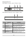
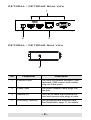
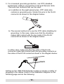
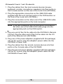
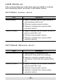
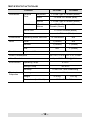
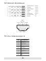
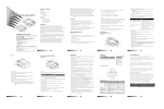
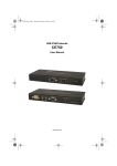
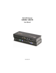
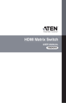
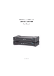
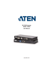
USB KVM Extender USER MANUAL CE700A FCC Information This is an FCC Class A product. In a domestic environment this product may cause radio interference in which case the user may be required to take adequate measures. This equipment has been tested and found to comply with the limits for a Class A digital device, pursuant to Part 15 of the FCC Rules. These limits are designed to provide reasonable protection against harmful interference when the equipment is operated in a commercial environment. This equipment generates, uses and can radiate radio frequency energy and, if not installed and used in accordance with the instruction manual, may cause harmful interference to radio communications. Operation of this equipment in a residential area is likely to cause harmful interference in which case the user will be required to correct the interference at his own expense. User Notice This ATEN product is specifically designed and manufactured for the operation and management of computer mainframe and communications equipment used in network management centers. As such, it may not be completely appropriate for those environments and sites where special standards for performance and high reliability are required – such as military equipment, traffic management, nuclear facilities, security systems, communications equipment, medical facilities, etc. RoHS This product is RoHS compliant. SJ/T 11364-2006 The following contains information that relates to China. CE700A User Manual Online Registration International http://support.aten.com North America http://www.aten-usa.com/product_registration Telephone Support International 886-2-8692-6959 China 86-10-5160-1602 Japan 81-3-5323-7178 Korea 82-2-467-6789 North America ATEN TECH 1-888-999-ATEN ATEN NJ 1-732-356-1703 United Kingdom 44-8-4481-58923 Technical Support For international online technical support – including troubleshooting, documentation, and software updates: http://support.aten.com For North American technical support: Email Online Technical Support Troubleshooting Documentation Software Updates Telephone ATEN TECH [email protected] ATEN NJ [email protected] ATEN TECH http://www.aten-usa.com/support ATEN NJ http://support.aten.com ATEN TECH http://www.aten-usa.com ATEN NJ http://www.aten.com ATEN TECH 1-888-999-ATEN ATEN NJ 1-732-356-1703 -3- Package Contents The CE700A USB KVM Extender package contains the following: 1 CE700AL USB KVM Extender (Local Unit) 1 CE700AR USB KVM Extender (Remote Unit) 1 USB KVM Cable (1.8 m) 2 Power Adapters 2 Rack Mount Kits 2 Grounding Wires 1 User Manual* 1 Quick Start Guide Check to make sure that all the components are present and that nothing got damaged in shipping. If you encounter a problem, contact your dealer. Read this manual thoroughly and follow the installation and operation procedures carefully to prevent any damage to the unit, and/or any of the devices connected to it. * Features may have been added to the CE700A since this manual was printed. Please visit our website to download the most up-to-date version of the manual. Copyright © 2009 ATEN® International Co., Ltd. Manual Part No. PAPE-1341-AT1G Manual Date: 2009-10-14 ATEN and the ATEN logo are trademarks of ATEN International Co., Ltd. All rights reserved. All other trademarks are the property of their respective owners. -4- Overview The CE700A is a USB KVM Extender with superior video quality and built-in ESD and surge protection that allows access to a computer system from a remote USB console (USB keyboard, monitor, and USB mouse). Because it allows access to a computer system from a remote console, the CE700A is perfect for use in any type of installation where you need to place the console where it is conveniently accessible, but you want the system equipment to reside in a safe location – away from the dust and dirt of the factory floor, or the harsh environmental influence of a construction site, for example. The CE700A is also useful for control and security purposes, where you can have the system unit in a secure area at the same time that you put the console in the most convenient location for user access. The CE700A improves on previous designs by: 1) incorporating 15KV ESD protection and 2KV surge protection; 2) providing superior video quality – up to 1920 x 1200 resolution; 3) using inexpensive Cat 5 cable, instead of bulkier, more expensive, standard cables, for a much neater, more convenient, more reliable data transfer connection; 4) it is able to sense the distance to the system and automatically adjusts the gain accordingly; and 5) it features a custom ASIC to ensure the utmost in reliability and compatibility. Setup is as easy as can be – simply connect the computer system box and local console to the Local CE700A Module; run the Cat 5 cable to the Remote CE700A Module (up to 150 meters away); and plug the remote console into the Remote Module. Note: You can control numerous remote systems from a single console by combining the CE700A with a KVM switch. -5- Features Local and Remote Units connect at distances up to 150 m using Cat 5e cable Dual console operation – control your system from both the local and remote USB keyboard, monitor, and mouse consoles Built-in ASIC for greater reliability and compatibility Auto Signal Compensation (ASC) USB Keyboard and USB Mouse Ports USB overcurrent detection and prevention Pushbutton operating mode selection (Local Unit only) – select between Local and Auto operating modes. Built-in 8KV/15KV ESD protection (Contact voltage 8KV; Air voltage 15KV) and 2KV surge protection Automatic gain control – adjusts signal strength to compensate for distance High resolution video – up to 1920 x 1200@60Hz (30 m ); 1600 x 1200@60Hz (100 m); 1280 x 1024@60Hz (150 m) Supports VGA, SVGA, SXGA, UXGA, WUXGA, and multisync monitors; local monitor supports DDC; DDC2; DDC2B Hot pluggable Rack mountable Easy to install – no software required – connecting cables to the devices is all it takes -6- System Requirements Consoles A VGA, SVGA, SXGA, UXGA, WUXGA, or Multisync monitor capable of the highest resolution that you will be using on the installation A USB keyboard A USB mouse Computers The following equipment must be installed on each computer that is to be connected to the system: A VGA, SVGA, SXGA, UXGA, WUXGA, or Multisync card USB Host Controller and Type A USB Port Cables For optimal signal integrity, and to simplify the layout, we strongly recommend that you use the high quality custom USB KVM Cable that is provided with this package. Cat 5e cable is the minimum required to connect the local and remote CE700A units. Cable of a lesser standard will result in degrading the video signal. For best performance, we strongly recommend Cat 5e cable. Supported Operating Systems OS Version Windows Linux 2000, XP, Vista RedHat 7.1 and higher SuSE 9.0 and higher Mandriva (Mandrake) 9.0 and higher UNIX FreeBSD 4.2 and higher Novell Netware 6.0 and higher -7- Components CE700AL (Local Unit) Front View 1 2 3 4 AUTO / LOCAL CE700AR (Remote Unit) Front View 5 6 REMOTE No. Component Description 1 KVM Port The custom USB KVM cable that links the unit to the computer plugs in here. 2 Remote LED 3 Local LED The CE700AL has two LEDs to indicate operating status. See LED Display, page 17, for details. 4 Operating Mode Selection Pushbutton This pushbutton toggles the operating mode between Auto and Local. See Operating Modes, page 16, for details. 5 Link LED 6 Remote LED The CE700AR has two LEDs to indicate operating status. See LED Display, page 17, for details. -8- CE700AL / CE700AR Rear View 1 2 3 CE700AL / CE700AR Side View 4 No. Component Description 1 Console Ports The local and remote console’s USB keyboard, USB mouse, and monitor plug into these ports. 2 Power Jack The power adapter cable plugs into this jack. 3 Remote I/O The Cat 5e cable that connects the local and remote units plugs in here. 4 Grounding Terminal The grounding wire attached here. See Installation, page 11, for details. -9- Hardware Setup Make sure that the power to any device that you connect to the installation has been turned off. You must unplug the power cords of any computers that have the Keyboard Power On function. Rack Mounting For convenience and flexibility, the CE700AL and CE700AR can be mounted on system racks. 1. Using the screws provided in the Rack Mount Kit, screw the mounting bracket into the top or bottom of the unit as shown: Phillips hex head M3 x 6 2. Screw the bracket into any convenient location on the rack. - 10 - Installation Grounding To prevent damage to your installation it is important that all devices are properly grounded. 1. Use the two grounding wires supplied with this package to ground both units by connecting one end of the wire to the grounding terminal, and the other end of the wire to a suitable grounded object. 2. Make sure that the computer that the CE700AL connects to and the monitor that the CE700AR connects to are properly grounded. STP Cable (Cat 5e or higher) up to 150 m AUTO / LOCAL - 11 - 3. For increased grounding protection, use STP (shielded twisted pair) cable to connect the Local and Remote Units. There are two methods that can be used: a) In addition to the eight paired wires, STP cable also contains a grounding wire. Solder this wire to the RJ-45 connector as shown in the diagram below: b) The second method is to use the STP cable shielding for grounding. In this case, make sure that the shielding makes tight contact with the top inside of the RJ-45 connector as shown in the diagram below: In either case, make sure that the sides of the RJ-45 connector make tight contact with the grounding contacts on the sides of the RJ-45 socket as shown in the diagram below: Setting up the USB KVM Extender system is simply a matter of plugging in the cables. Refer to the installation diagram on the following page and do the following: - 12 - Connecting the Cables 1. Plug the cables from the local console devices (mouse, keyboard, monitor, microphone, speakers) into their ports on the Console section on the rear of the Local Unit (CE700AL). 2. Plug the appropriate connectors on the USB KVM cable supplied with this unit into their ports on the KVM section on the front of the Local Unit (CE700AL). 3. Plug the connectors on the other end of the USB KVM cable into the appropriate ports on the local computer. Note: If you are combining the CE700A with a KVM switch, the other end of the USB KVM cable plugs into the appropriate ports on the KVM switch. 4. Plug one end of the Cat 5e cable into the CE700AL's Remote I/O port. Plug the other end of the Cat 5e cable into the I/O port of the Remote Unit (CE700AR). 5. Plug one of the power adapters (supplied with this package) into an AC source; plug the adapter's power cable into the CE700AL's Power Jack 6. Plug the cables from the remote console devices into their ports on the Console side of the CE700AR. 7. Plug the second power adapter (supplied with this package) into an AC source; plug the adapter's power cable into the CE700AR's Power Jack. - 13 - CE700AL / CE700AR Rear View 4 CE700AL 5 1 Cat 5e cable 4 CE700AR 7 6 - 14 - CE700AL Front View AUTO / LOCAL 2 Local PC 3 USB KVM Cable Set - 15 - Operating Modes The CE700A USB KVM Extender system has three operating modes: Local, Auto, and Remote, as shown in the table, below: Mode Description Local Only the local console has KVM access. The remote console’s keyboard and mouse input is disabled. Auto Both the local and remote consoles can have KVM access, but not at the same time. The console without access has to wait until the active console stops inputting data before it can gain access. Remote The remote console has KVM access. Remote cannot be selected; it can only occur when the pushbutton on the CE700AL is set to Auto and the local console is idle. If the remote console is then idle for more than five seconds, the local console can gain access. Note: The default operating mode is Auto. - 16 - LED Display The Local and Remote Units each have two LEDs to indicate their operating status, as shown in the tables, below: CE700AL (Local Unit) LED Local (Green) Indication Lights to indicate that the local console is active (Remote LED is off) Off when remote console is active Flashes to indicate Auto mode (neither console is active) Remote (Green) Lights to indicate that the remote console is active (Local LED is off) Off when local console is active Flashes to indicate Auto mode (neither console is active) CE700AR (Remote Unit) LED Link (Green) Indication Lights steadily to indicate that the connection to the local unit is working. Flashes to indicate a problem with the connection to the local unit (remote LED is off) Remote (Green) Lights to indicate that the remote console is active (Local LED is off) Off when local console is active Flashes to indicate Auto mode (neither console is active) - 17 - Specifications Function Connectors Console Ports KVM Ports CE700AL Keyboard CE700AR 1 x USB Type A Female (White) Video 1 x HDB-15 Female (Blue) Mouse 1 x USB Type A Female (White) KB / Video / Mouse Unit to Unit 1 x SPHD-17 Female (Green) N/A 1 x RJ-45 Female (Black) Power 1 x DC Jack (Black) Pushbuttons Operating Mode Selection LEDs Local 1 (Green) N/A Remote 1 (Green) 1 (Green) N/A 1 (Green) Link Emulation Keyboard / Mouse DC 5.3V, 2.31W DC 5.3V, 2.84W Video Resolution Up to 1920 x 1200 @ 60 Hz Operating Temp. 0–50ºC Storage Temp -20–60ºC Humidity Physical Properties N/A USB Power Consumption Environment 1 x Pushbutton 0–80% RH, Non-condensing Housing Metal Weight 0.32 kg Dimensions (L x W x H) - 18 - 0.31 kg 12.50 x 8.15 x 2.5 cm TP Wiring Diagrams 1 1 WHITE/ORANGE /VOUTB 2 2 ORANGE VOUTB 3 3 WHITE/GREEN /VOUTG 6 6 GREEN VOUTG 4 4 BLUE /VOUTR 5 5 WHITE/BLUE VOUTR 7 7 WHITE/BROWN /DO 8 8 BROWN DO PAIR 3 PAIR 2 PAIR 1 PAIR 4 1 2 3 4 5 6 7 8 W-O O W-G Bl W-Bl G W-Br Br JACK POSITIONS T568B AT&T 258A TP Pin Assignments Pin Assignment 1 V OUT B 2 /V OUT B 3 V OUT G 4 V OUT R 5 /V OUT R 6 /V OUT G 7 /DO 8 DO - 19 - Troubleshooting Problem Action No video Make sure that all cables are securely plugged into their sockets. Poor video quality. The video quality can be improved by reducing the refresh rate. About SPHD Connectors This product uses SPHD connectors for its KVM and/or Console ports. We have specifically modified the shape of these connectors so that only KVM cables that we have designed to work with this product can be connected. Limited Warranty IN NO EVENT SHALL THE DIRECT VENDOR'S LIABILITY EXCEED THE PRICE PAID FOR THE PRODUCT FROM THE DIRECT, INDIRECT, SPECIAL, INCIDENTAL OR CONSEQUENTIAL DAMAGES RESULTING FROM THE USE OF THE PRODUCT, DISK OR ITS DOCUMENTATION. The direct vendor makes no warranty or representation, expressed, implied, or statutory with respect to the contents or use of this documentation, and specially disclaims its quality, performance, merchantability, or fitness for any particular purpose. The direct vendor also reserves the right to revise or update the device or documentation without obligation to notify any individual or entity of such revisions, or update. For further inquires please contact your direct vendor. - 20 -