1
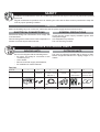
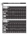
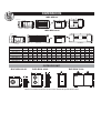
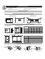
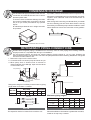
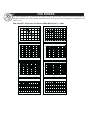
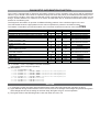
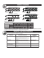
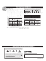
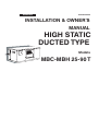
ENGLISH 035T83350-000 INSTALLATION & OWNERS MANUAL HIGH STATIC DUCTED TYPE Models MBC-MBH 25-90 T SAFETY TE AL NIC CH GU Installation and maintenance of this air conditioning system should only be carried out by trained and qualified personnel. Regular maintenance operations such as cleaning the coils and air filters must be performed to keep the units in proper operating condition. IDE CAUTION Before undertaking any work on the unit, make sure that the power supply has been disconnected. ELECTRICAL CONNECTIONS GENERAL PRECAUTIONS All electrical wiring and connections must comply with local standards. Disconnecting device must have a contact separation of at least 3 mm with all pole disconnected. Check that the power supply available agrees with nameplate voltage. Use adequate line protection. The unit must be grounded. INDOOR & OUTDOOR UNITS INDOOR UNITS OUTDOOR UNITS Each unit is shipped with the following items: An indoor unit ready for connection to the condensing unit, User's Guide, Remote Controller supply with batteries, An Installation & Owner's Manual. The units are shipped complete with a charge of R22/ R407C refrigerant sufficient for a piping length of 7.5 meters. Part List Part No. Name of Part 1 Indoor unit 2 Screw and Anchor set 3 Connection Cable 5 m (for outdoor coil sensor MBH 25-90 T) 4 5 IR kit 4.50 or 15 m (optional) 6 Remote Controller and Bracket Remote Installation & Owners Manual And Users Guide MBC-MBH 25-90 T COOL & DRY COOL & DRY Installation & Owner's Man ual Quantity x1 x1 x1 x1 x1 User's Guide x1 TECHNICAL SPECIFICATIONS R22 Models Power Supply Power Consumption Running Current Max. Starting Current Refrigerant Type Refrigerant Charge (BOC/BOH) Air flow Input Power Running Current Height Width Dimension Depth Weight System Operation Control Fan Indoor Unit Power Supply Compressor Dimension Weight (CL/HP) Type Piping Outdoor Unit Power Supply Pipe Size Indoor Unit Outdoor Unit V/Ph/Hz Ph kW A A gr V/Ph/Hz Ph m3/h W A mm mm mm kg V/Ph/Hz Ph Qty Compressor Type mm Height mm Width mm Depth kg Suction Liquid inch inch MBC-MBH 55 50 45 BOC-BOH 55 45 45 35 25 220-240/1/50 or 380-415/3/50 3 3 3 1 1 3 1 3 6.16 5.61 5.61 4.12 4.04 4.39 4.43 3.18 15.7 12.9 12.9 19.6 10.0 20.2 10.5 14.6 55 55 79 42 55 82 70 39 R22 4100 3450 2600 2800/2500 3450 1650/1600 220-240/1/50 1 1 1 1 1 3700 3700 3100 2350 1650 1141 1000 1000 840 661 5.09 4.00 4.00 3.88 3.18 400 400 400 400 400 1204 1204 1018 924 710 620 620 620 620 620 77 70 66 56 40 Wired/Wireless Control with LCD Display 220-240/1/50 or 380-415/3/50 3 3 3 3 1 1 1 3 1 1 1 1 1 1 Rotary Reciprocating Rotary Scroll 900 900 1142 1142 1142 696 850 850 1060 850 850 850 285 285 345 285 285 285 76/77 109/111 87/88 87/88 65/67 90/91 91/92 Flare+Nuts 5/8 5/8 3/4 3/4 3/4 5/8 3/8 3/8 3/8 3/8 3/8 3/8 65 35 25 90 75 BVC-BVH 65 75 90 3 7.07 17.0 66 3 8.88 25.8 80 3 9.83 26.7 114 6400 1000 1000 1 3950 1143 4.97 400 1404 620 88 1 5150 1480 6.93 500 1695 868 96 1 5000 1480 6.93 500 1695 868 101 3 1 3 1 3 1 1142 1060 345 129/131 1065 1650 650 221 3/4 3/8 1-1/8 1/2 Scroll 1065 1650 650 261 Sweat 1-1/8 1/2 R407C Models Power Supply Fan Power Consumption Running Current Max. Starting Current Refrigerant Type Refrigerant Charge (BOL/BOM) gr V/Ph/Hz Ph m3/h W A mm mm mm kg Power Supply V/Ph/Hz Ph Indoor Unit Power Supply Air flow Input Power Running Current Height Width Dimension Depth Weight System Operation Control Compressor Dimension Weight (CL/HP) Type Piping Outdoor Unit Indoor Unit Outdoor Unit V/Ph/Hz Ph kW A A Pipe Size Qty Compressor Type mm Height mm Width mm Depth kg Suction Liquid inch inch 25 25 1 4.37 20.6 91 55 65 65 55 45 220-240/1/50 or 380-415/3/50 3 3 3 3 7.42 6.57 6.00 6.00 17.6 16.3 14.8 14.8 66 55 55 55 R407C 6400 4100 3450 3450 220-240/1/50 1 1 1 1 3950 3700 3700 3100 1143 1141 1000 1000 4.97 5.09 4.00 4.00 400 400 400 400 1404 1204 1204 1018 620 620 620 620 88 77 70 66 Wired/Wireless Control with LCD Display 220-240/1/50 or 380-415/3/50 3 3 3 3 1 1 1 1 Scroll 1142 1142 1142 1142 1060 1060 1060 1060 345 345 345 345 129/131 109/111 109/111 109/111 Flare+Nuts 3/4 3/4 3/4 3/4 3/8 3/8 3/8 3/8 45 3 4.25 10.3 44 1650/1600 2100 1 1650 661 3.18 400 710 620 40 1 2350 840 3.88 400 924 620 56 1 1 MBL-MBM 75 BOL-BOM 35 1 3.27 15.4 74 50 45 35 3 1 1 1 Rotary 696 850 285 65/67 900 1060 345 89/91 5/8 3/8 5/8 3/8 Remark: The above design and specifications are subject to change without prior notice for product improvement. 90 BVL-BVM 75 90 3 9.19 25.8 95 3 9.96 26.7 114 - - 1 5150 1480 6.93 500 1695 868 96 1 5000 1480 6.93 500 1695 868 101 3 1 3 1 Scroll 1065 1650 650 261 1065 1650 650 221 1-1/8 1/2 Sweat 1-1/8 1/2 DIMENSIONS MBC-MBH 25 CONTROL BOX LIQUID LINE SUCTION LINE REAR VIEW LH VIEW FRONT VIEW RH VIEW MBC-MBH 35-90 CONTROL BOX LIQUID LINE SUCTION LINE REAR VIEW LH VIEW A1 235 309 149 242 242 342 434 434 MODEL MBC-MBH 25 MBC-MBH 35 MBC-MBH 45 MBC-MBH 50 MBC-MBH 55 MBC-MBH 65 MBC-MBH 75 MBC-MBH 90 A2 235 309 149 242 242 342 313 313 C 74 74 74 74 74 74 75 75 B 240 306 720 720 720 720 948 948 RH VIEW E 124 124 124 124 124 124 245 245 D 512 726 820 1006 1006 1206 1375 1375 F 400 400 400 400 400 400 500 500 FRONT VIEW H 264 264 250 250 250 304 349 349 G 710 924 1018 1204 1204 1404 1695 1695 I 98 98 95 95 95 73 124 124 J 30 30 30 30 30 30 30 30 K 560 560 560 560 560 560 808 808 L 30 30 30 30 30 30 30 30 M 331 331 331 331 331 331 431.5 431.5 N 51 51 51 51 51 51 51 51 OUTDOOR UNIT BOC-BOH 25-35 BOC-BOH 45-65 D W W BVC-BVH 75-90 D W D H H Outdoor unit dimensions are shown in the Technical Specifications table. H INSTALLATION Unit installation details: condensate water drainage connections unit wiring connection unit mounting refrigerant piping connections UNIT CLEARANCES A minimum of clearance is necessary around the units to ensure proper air circulation and easy access for maintenance. CLEARANCE REQUIRED FOR INDOOR UNITS MBC-MBH 25-65 250 MBC-MBH 75-90 500 150 500 150 CLEARANCE REQUIRED FOR OUTDOOR UNITS BOC-BOH 45-65 BOC-BOH 25-35 A A B D B D E Unit E C C A B C D E 25 200 400 100 210 600 35 200 400 100 210 800 BOC-BOH 45 200 400 100 300 800 55 200 400 100 300 800 65 200 400 100 300 800 BVC-BVH 75-90 Unit A B C D E F BVC-BVH 75-90 400 200 100 210 800 800 OUTDOOR UNIT INSTALLATION OK No obstacle air flow. Obstacle air flow. CONDENSATE DRAINAGE Condensate drainage is provided on the unit. The connection is located at the rear. Use a 19 mm diameter plastic tube. To ensure correct condensate drainage, the drain line must be installed with a gradient of at least 2% (2 cm per meter) and without any upward slopes. An elbow trap at least 50 mm in height must also be provided. If possible, install a U bend fitted with an inspection cap. Where the condensate lines from several units are joined together, each individual outlet must be fitted with an elbow trap. After routing and connecting condensate lines, pour water into the collecting pan and check that it drains correctly. An auxiliary condensate pump could be installed in cases where drain lines cannot be routed the correct gradient. 50mm Condensate drain connection U TRAP REFRIGERANT PIPING CONNECTIONS Prefabricated refrigerant piping is available as an accessory. If this is used, piping and insulating materials employed must be compatible with this type of installation. The pre-charged outdoor unit does not require charging if piping length is 7.5 m or less. However, the interconnecting piping and the indoor unit must be pumped down before releasing R22/R407C refrigerant into them from the outdoor unit. 1 - Remove the cap from the service valve. 2 - Connect the line to a vacuum pump and down to 5 pa. 3 - When pump down is finished, wait 15 minutes to detect potential circuit leakage. Open service valves on the outdoor unit. Low pressure High pressure L D Collector Liquid valve Pressure tap Gas valve Refrigerant charge to be added per extra meter of piping length when more than 7.5 meters. Unit size g/m BOC-BOH BVC-BVH 25 35 45 55 65 75 90 40 40 60 60 60 60 60 Maximum piping lengths Gas line Liquid line Outdoor unit L H Indoor unit R22/R407C NOTE The expansion device is located in the outdoor unit. Unit size 25 35 45 55 65 D (m) 22 22 26 26 26 L (m) 25 25 30 30 30 H (m) 20 20 24 24 24 NOTE Where the difference in elevation is greater than 5 meters, install an oil trap every 5 meters. FAN SPEEDS For ducted installations, check airflow and static pressure against values shown in the following diagrams. Insufficient airflow can cause operating problems such as icing which may damage the compressor in the outdoor unit. FAN CURVES : High Static Air Blower (MBC-MBH 25-90 T) - 50Hz Fan Curve MBC-MBH 25 / 50Hz Fan Curve MBC-MBH 35 / 50Hz 250 300 H 250 200 Static Pressure ( Pa ) Static Pressure ( Pa ) 150 L 100 50 H M L M 200 150 100 50 0 0 500 700 900 1100 1300 1500 1700 500 1900 700 900 1100 1300 Air Flow ( m /h ) Fan Curve MBC-MBH 45 / 50Hz 1700 1900 2100 2300 2500 2700 Fan Curve MBC-MBH 50 / 50Hz 300 300 250 H 200 M L 150 H 250 Mevcut D& Statik Basnç (Pa) Static Pressure ( Pa ) 1500 Air Flow ( m3/h ) 3 100 50 M 200 L 150 100 50 0 500 700 900 1100 1300 1500 1700 1900 2100 2300 2500 2700 2900 3100 0 3300 1000 1200 1400 1600 1800 2000 Air Flow ( m3/h ) 2200 2400 2600 2800 3000 3200 3400 3600 3800 4000 Air Flow ( m3/h ) Fan Curve MBC-MBH 55 / 50Hz Fan Curve MBC-MBH 65 / 50Hz 300 350 300 250 H H Static Pressure ( Pa ) Static Pressure ( Pa ) 250 200 M L 150 100 50 0 1000 M 200 150 L 100 50 1200 1400 1600 1800 2000 2200 2400 2600 2800 3000 3200 3400 3600 3800 0 1000 1200 1400 1600 1800 2000 2200 2400 2600 2800 3000 3200 3400 3600 3800 4000 4200 4400 4000 Air Flow ( m3/h ) Air Flow ( m3/h ) Fan Curve MBC-MBH 90 / 50Hz Fan Curve MBC-MBH 75 / 50Hz 400 350 350 Static Pressure ( Pa ) Static Pressure ( Pa ) 250 200 150 M 250 200 L 150 100 100 50 50 0 500 H 300 H M L 300 1000 1500 2000 2500 3000 Air Flow ( m3/h ) 3500 4000 4500 5000 5500 0 500 1000 1500 2000 2500 3000 Air Flow ( m3/h ) 3500 4000 4500 5000 5500 UNIT CONTROLLER OPERATION EMERGENCY OPERATION Units are equipped with a switch to run in emergency operation mode. The switch is on the infrared receiver board where the LED lights are located, or in the case of wall mount units it can be accessed by opening the front grill. This switch is used for manual operation upon expiration of service life of remote control batteries, or upon occurrence of a problem. Pushing the emergency switch first turns it on; pushing it again turns it off (toggle action). During emergency operation, the remote controller cannot be used and the power LED light will flash in intervals, while the other LED lights will indicate the operation of the Diagnostic Codes. In Emergency Operation in cool mode, the temperature will be set at 24°C and the fan on Auto. In heating the unit will switch to auto mode at a temperature set point of 24°C and the fan will run on auto mode. AUTO RESTART FUNCTION Upon suspension of electrical power supply during operation for any reason, when supply of power resumes the unit operation will restart automatically according to all parameters set before the suspension of power. ANTI-ICE AND ANTI OVERHEATING This feature is used to prevent the evaporator unit from freezing during cool or dry operation. During execution of anti-ice operation and anti-overheating, the compressor will stop operating and the fan will continue to run until the coil temperature reaches predetermined set points, at which time the unit will resume normal operation. LOW VOLTAGE The feature is used to protect against any damage to the unit caused by fluctuation of voltage. If voltage is lower than the lower limit for approximately 10 seconds or longer, compressor operation will be temporarily stopped. Normal operation will resume when the voltage returns above the set limit for a minimum of 10 seconds. If the time elapsed is less than 3 minutes then the compressor start up will be delayed until 3 minutes has passed. SYSTEM OPERATION MODE SELECTION There are five different operating modes; Cooling mode Automatic mode (Heat Pump Units Only) Dry mode Heating mode (Heat Pump Units Only) Fan mode The required mode can be selected by pressing theSYSTEM button until the corresponding mode symbol appears on the display. In automatic mode the unit operates automatically between Cool and Heat modes based on the change in the room temperature and the temperature set point entered on the control. ROOM TEMPERATURE SETTING Press the TEMP button up or down to change the setting to the desired room temperature. The setting range is from 16°C to 32°C. Operating the unit below 16°C may result in the coil freezing. FAN SPEED AND LOUVER POSITION SETTING Low - Medium - High speeds are available. Press the FAN button for the desired airflow. The FAN symbol shows the speed that has been selected. Automatic fan speed is available in Cooling and Heat modes only. When the dehumidification mode is used, the fan speed is set automatically. The SWEEP button is used to control the movement of the air louvers. By pressing the button, the louver can be set in either the fixed position or by pressing again, it will move in a sweeping motion to distribute the air in the room. Applicable only for units with air sweep. FILTER CARE AND FILTER ALARM To keep your air conditioning unit in peak condition, the filters should be cleaned regularly, i.e. once a month, or more frequently depending on conditions. To do this; Remove the filters from the unit Wash them in soapy water (do not use detergent) Dry the filters and put them back in place on the unit. To clean the unit casing, use a damp cloth. The control is equipped with a filter Alarm; based on the hours of operation, and indicated by all of the lights flashing (see the Diagnostic Chart for details), to remind you to change the filter. To reset the alarm press theFILTER button on the remote control. If you fail to press the RESET button the alarm will automatically reset after 6 hours of operation. CLOCK AND TIMER FUNCTIONS To set the clock press the CLOCK button for at least 5 seconds, until the CLOCK symbol flashes. Then use the TIMER buttons to set the desired time. Finally, press the CLOCK button again to enter the time that has been set. The control is equipped with a timer that can set both start and stop times for the unit. The operational settings that have been entered on the control will be the ones that the control follows when it starts. To use the timer function follow these steps; STOP START 1. Turn the unit on. 2. Press the START button 3. Adjust the clock display to the desired start time 4. Press Enter The START symbol will be shown on the display, indicating that a start time has been programmed. 1. With the unit on. 2. Press the STOP button 3. Adjust the clock display to the desired stop time 4. Press Enter The STOP symbol will be shown on the display, indicating that a stop time has been programmed. Lights will indicate that the unit timer has been set. After the unit has either been started or stopped by the timer, the set time will remain in the program, however the START or STOP button must be pressed again to reset the timer function. To cancel either the Start or Stop Timer setting press the CANCEL button . To check the time that has been entered either for starting or stopping the unit, press the appropriateSTART - STOP button and the time will be displayed. Press the button again to go back to the clock display. SLEEP TIMER FUNCTION Sleep mode, which can be used in Cool and Heat modes is a program in the control which is designed to give a comfortable room environment during sleeping hours. At the start of sleep mode the unit will operate in cooling or heating mode continuously until the temperature set point is reached. It will then run for a further 1 hour period at this setting. After this, the temperature set point will automatically be raised +1°C every hour (cooling) or lowered 1°C every hour (heating) until the sleep (shut off) time is reached. At this time the unit will shut off. Sleep mode is set by pressing the SLEEP button which will set the shut off time in 30 minute increments, starting from the time shown on the clock when theSLEEP button is first pressed. In sleep mode the unit will follow the settings that were entered at the time that Sleep mode was started. Sleep mode can be cancelled by pressing the CANCEL button at any time. DIAGNOSTIC INFORMATION FUNCTION The control is equipped with a diagnostic information system to report operation of the unit as well as operational failures. If your remote control does not operate properly first check the polarity of the batteries and that they are in good working condition. Also make sure that the control is pointed directly at the air conditioning unit when you are using it, that the distance is a maximum of 10 meters, and that there are no obstacles between the remote control and the air conditioning unit. The Diagnostic Information is reported via different flashing patterns of the 3 indicator lights on the unit. The chart below shows the light patterns for the various operational, protection and failure modes. This feature is intended to provide information to the consumer as well as for service of the units.OTES Timer Operation Power Status O E-1 Room sensor Temperature fail O Indoor coil sensor fail O E-1 O X *1 E-5 Prevention by Anti Overheating (Indoor coil sensor > 62°C) Prevention by Anti Overheating (Indoor coil sensor 65°C) *1 X E-5 Heat Mode X *1 F-1 Indoor coil sensor < 20°C Heat Mode X *1 F-1 Indoor coil sensor < 28°C X *1 E-4 Over Cool X *1 E-4 De-Ice Cool/Dry Mode X *1 F-2 40°C < Indoor coil sensor E-4 : COOL Cycle Fail O O E-5 : HEAT (Cool Fail, Heat Fail) *1 X E-2 Water full alarm (For cassette type) F-3 *1 S Filter alarm *1 E-1 Outdoor Sensor fail X X E-3 *1 Defrost (Normal) Defrost (Failure) E-1 X *1 (1) X: ON O: OFF S: ON/OFF by condition (Influence by the prevention mode isnt taken) (2) *1: Indication : X, F-2, F-3 (Condition of the timer reservation) X,O (Condition of the compressor operation) (3) LED indication - E-1 ON =0.5 sec OFF = 7 sec - E-2 ON =0.5 sec OFF = 0.5sec for 2 Times. LED off for 6 sec. Then repeat cycle. - E-3 ON =0.5 sec OFF = 0.5sec for 3 Times. LED off for 5 sec. Then repeat cycle. - E-4 ON =0.5 sec OFF = 0.5sec for 4 Times. LED off for 4 sec. Then repeat cycle. - E-5 ON =0.5 sec OFF = 0.5sec for 5 Times. LED off for 3 sec. Then repeat cycle. - F-1 ON = 0.5 sec OFF = 0.5sec for Continuously. - F-2 ON = 1.5 sec OFF = 0.5sec for Continuously. - F-3 ON = 0.5 sec OFF = 1.5sec for Continuously. Mode Reset-Call Service Technician Reset-Call Service Technician Reset-Call Service Technician Reset-Call Service Technician Reset-Call Service Technician Reset-Call Service Technician Reset-Call Service Technician Protection Reset-Call Service Technician Reset-Call Service Technician Protection Protection Reset-Call Service Technician Protection Protection NOTES 1) In emergency mode, the Power light will flash and the other lights will indicate the operation as above. 2) Lights will flash during the time that the units is held off, due to Low Voltage. If the voltage has passed through the reset voltage and the unit is waiting for the time delay, the lights will go to normal operation. 3) The lights will show the LED Diagnostic Code even when the unit is off. WIRING DIAGRAM MBC/BOC 25-35 Cooling Only L MBH/BOH 25-35 Heat Pump Unit N 1 2 Indoor unit Indoor unit N 1 2 Outdoor unit Outdoor unit Power supply 220-240V/1Ph/50Hz 208-230V/1Ph/60Hz Power supply 220-240V/1Ph/50Hz 208-230V/1Ph/60Hz MBC/BOC 35-65 - Cooling Only N L1 L2 L3 1 MBH/BOH 35-65 Heat Pump Unit 2 N 1 2 Indoor unit Indoor unit Outdoor unit Outdoor unit Power supply 380-415V/3Ph/50Hz 480V/3Ph/60Hz Power supply 380-415V/3Ph/50Hz 480V/3Ph/60Hz Wiring sizes BOC-BOH Unit 25 mm 2 Power supply Interconnection Ph 35 3x4 1 3 45 5 x 2.5 1 3 1 3 3 75 3 10 16 16 16 16 5 x 10 3 3 3 x 2.5 4 x 2.5 10 90 5 x 10 3 x 2.5 (Indoor/Outdoor) Heating mm2 A 65 5x4 Cooling mm 2 Fuse (slow-blow) BVC-BVH 55 4 x 2.5 16 16 16 16 For details of indoor unit and outdoor unit wiring, see the diagram supplied inside the units. Start the unit and check operation both in cooling and heating mode. SERVICE AND MAINTENANCE The units are designed to operate for long periods of time with a minimum of maintenance. However, the following operations must be performed regularly. COMPONENT RECOMMENDED FREQUENCY MAINTENANCE OPERA TIONS Air filter 1 - Clean with a vacuum cleaner or tap gently then wash in warm water (40°C) with a mild detergent. 2 - Rinse and dry before replacing on unit. 3 - Never use petrol, alcohol or any other chemical product. Every month or more often if necessary. Unit casing 1 - Remove dust from the front panel with a soft duster or wipe a dump cloth with a mild soap solution. 2 - Never use petrol, alcohol or any other chemical product. Every month or more often if necessary. Drain pan and evacuation piping 1 - Clean and check for obstructions. Each season before start up. Indoor / Outdoor coils 1 - Check condition and remove dust from between coil fins. Each season before start up. Compressor 1 - No maintenance required. TECHNICAL APPENDIX Unit Capacity Capacity correction factor for piping length (C2) Total cooling capacity can be determined by using correction factors C1, C2 and C3. Given cooling capacity = Cooling capacity at standard rating conditions x C1 x C2 x C3. C1 = Capacity correction factor for temperature C2 = Capacity correction for piping length C3 = Capacity correction for indoor unit fan speed Capacity correction factor for indoor fan speed (C3) Inlet air wet bulb temperature, indoor unit (CWB) Capacity correction factor for temperature 35 Operating temperature limits Capacity correction factor C1 30 120% Operating temperature range 110% 25 100% 90% 20 85% R.C. 15 10 20 25 30 35 40 45 Air intake dry bulb temperature, outdoor unit (CDB) R.C. = Standard rating conditions : Indoor 27 ° C DB / 19.5°C WB Outdoor 35°C DB / 24°C WB DECLARATION OF CONFORMITY DE - COMMISSIONING DISMANTLING & DISPOSAL This product contains refrigerant under pressure, rotating parts, and electrical connections which may be a danger and cause injury! All work must only be carried out by competent persons using suitable protective clothing and safety precautions. Read the Manual Risk of electric shock Unit is remotely controlled and may start without warning 1. Isolate all sources of electrical supply to the unit including any control system supplies switched by the unit. Ensure that all points of electrical and gas isolation are secured in the OFF position. The supply cables and gas pipework may then be disconnected and removed. For points of connection refer to unit installation instructions. 2. Remove all refrigerant from each system of the unit into a suitable container using a refrigerant reclaim or recovery unit. This refrigerant may then be reused, if appropriate, or returned to the manufacturer for disposal. Under No circumstances should refrigerant be vented to atmosphere. Where appropriate, drain the refrigerant oil from each system into a suitable container and dispose of according to local laws and regulations governing disposal of oily wastes. 3. Packaged unit can generally be removed in one piece after disconnection as above. Any fixing down bolts should be removed and then unit lifted from position using the points provided and equipment of adequate lifting capacity. Reference MUST be made to the unit installation instructions for unit weight and correct methods of lifting. Note that any residual or spilt refrigerant oil should be mopped up and disposed of as described above. 4. After removal from position the unit parts may be disposed of according to local laws and regulations. YORK ® International Corporation 035T83350-000