1
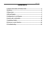
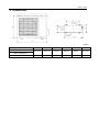
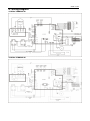
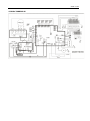
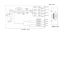
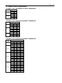
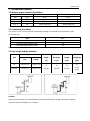
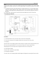
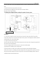
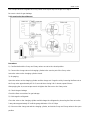
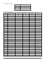
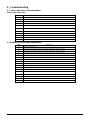
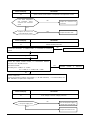
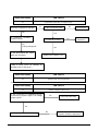
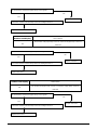
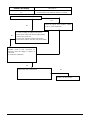
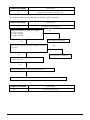
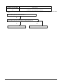
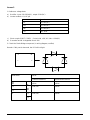
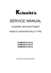
ODMI-A-1110
SERVICE MANUAL
MIDEA AIRCONDITIONER
North America MARKET
DC INVERTER MULTI TYPE
M2OC-18HRDN1-M
M3OC-27HRDN1-M
M4OC-36HRDN1-M
DC MULTI OUTDOOR UNITS
ODMI-A-1110
CONTENTS
1. General information of Outdoor Units ................................................. 3
2.Features.................................................................................................. 4
3. Dimensions ............................................................................................ 5
4. Wiring Diagram ...................................................................................... 6
5. Refrigeration Cycle Diagram ................................................................ 8
6. Indoor units combination.................................................................... 10
7. Installation Details ............................................................................... 11
8. Electronic control function ................................................................. 20
9. Troubleshooting .................................................................................. 25
ODMI-A-1110
1. General information of Outdoor Units
Model name
Dimension (mm(in))
Compressor
M2OC-18HRDN1-M
845x320x700(33.3x12.6x27.6)
DA130S1C-20FZ
M3OC-27HRDN1-M
845x320x700(33.3x12.6x27.6)
DA150S1C-20FZ
M4OC-36HRDN1-M
990x345x965(39x13.6x38)
TNB306FPGMC-L
ODMI-A-1110
2.Features
Outdoor unit
Power relay control
Low noise air flow system
Hydrophilic aluminum fin
The hydrophilic fin can improve the heating efficiency at operation mode.
4 way valve control
It is only operated in the heating operation mode except defrosting operation.
Anti-rust cabinet
Valve protection cover
It protects the valves and prevents water from dripping.
Discharge pipe temperature protection
Compressor crankcase heater
ODMI-A-1110
3. Dimensions
mm(in)
Model
W
D
H
W1
A
B
845((33.3)
320(12.6)
700(27.6)
908(35.7)
560(22)
335(13.2)
990(39)
345(13.6)
965(38)
1075(42.3)
624(24.6)
366(14.4)
M2OC-18HRDN1-M
M3OC-27HRDN1-M
M4OC-36HRDN1-M
ODMI-A-1110
4. Wiring Diagram
4.1 M2OC-18HRDN1-M
4.2 M3OC-27HRDN1-M
ODMI-A-1110
4.3 M4OC-36HRDN1-M
ODMI-A-1110
5. Refrigeration Cycle Diagram
8.1 Refrigeration circuit drawing of inverter dual zone
Axial flow fan
EXVA
Exhaust
temp. sensor
Main
Capillary
Auxiliary
Capillary
Filter A
Liquid valve A
Filter B
Liquid valve B
Capillary A
EXVB
Condenser
4-way
valve
Check
Valve
Coil temp.
sensor
Evaporator
Cross
Indoor pipe out
temp. sensor A
Gas valve A
Indoor pipe out
temp. sensor B
Compressor
Gas valve B
Indoor Unit
Outdoor Unit
5.2
flow fan
Capillary B
Refrigeration circuit drawing of inverter tri-zone
Axial flow fan
Exhaust
temp. sensor
Main
Capillary
Condenser
4-way
valve
Coil temp.
sensor
Auxiliary
Capillary
Check
Valve
Capillary A
EXV A
Capillary B
EXV B
Capillary C
EXV C
Liquid valve A
Filter A
Liquid valve B
Filter B
Liquid valve C
flow fan
Evaporator
Filter C
Cross
Compressor
Outdoor Unit
8.3 Refrigeration circuit drawing of inverter qua-zone
Indoor pipe out
temp. sensor A
Gas valve A
Indoor pipe out
temp. sensor B
Gas valve B
Indoor pipe out
temp. sensor C
Gas valve C
Indoor Unit
ODMI-A-1110
ODMI-A-1110
6. Indoor units combination
6.1 Indoor unit combination for M2OC-18HRDN1-M
Comb.
Dual(1x1)
Dual (1x2)
Combinations
Unit A Unit B
9k
—
12k
—
18k
—
9k
9k
9k
12k
12k
12k
6.2 Indoor unit combination for M3OC-27HRDN1-M
Comb.
TRI (1x1)
TRI (1x2)
TRI (1x3)
Combinations
Unit A Unit B Unit C
9k
—
—
12k
—
—
18k
—
—
9k
9k
—
9k
12k
—
9k
18k
—
12k
12k
—
12k
18k
—
9k
9k
9k
9k
9k
12k
9k
12k
12k
6.3 Indoor unit combination for M4OC-36HRDN1-M
Comb.
QUA (1x1)
QUA (1x2)
QUA (1x3)
QUA(1x4)
Unit A
9k
12k
18k
9k
9k
9k
12k
12k
18k
9k
9k
9k
9k
9k
9k
12k
12k
12k
9k
9k
9k
9k
9k
9k
9k
12k
12k
Combinations
Unit B Unit C
—
—
—
—
—
—
9k
—
12k
—
18k
—
12k
—
18k
—
18k
—
9k
9k
9k
12k
9k
18k
12k
12k
12k
18k
18k
18k
12k
12k
12k
18k
18k
18k
9k
9k
9k
9k
9k
9k
9k
12k
9k
12k
12k
12k
12k
12k
12k
12k
12k
12k
Unit D
—
—
—
—
—
—
—
—
—
—
—
—
—
—
—
—
—
—
9k
12k
18k
12k
18k
12k
18k
12k
18k
ODMI-A-1110
7. Installation Details
7.1 Wrench torque sheet for installation
Outside diameter
Torque
Additional tightening torque
mm
inch
N.cm
N.cm
$ 6.35
1/4
1500(153kgf.cm)
1600(163kgf.cm)
$ 9.52
3/8
2500(255kgf.cm)
2600(265kgf.cm)
$ 12.7
1/2
3500(357kgf.cm)
3600(367kgf.cm)
7.2 Connecting the cables
The power cord of connect should be selected according to the following specifications sheet.
For power line:
Unit
AWG
dual-zone(18K outdoor unit)
14
tri-zone (27K outdoor unit).
14
qua-zone(36K outdoor unit)
12
For indoor unit and outdoor unit connection line, 16AWG is ok for all.
7.3 Pipe length and the elevation
Pipe size
Unit
Gas
Liquid
9K
3/8•• ($ 9.53)
1/4•• ($ 6.35)
12K/18K
1/2•• ($ 12.7)
1/4•• ($ 6.35)
Standard
Max.
Max.
Additional
length
Elevation
Length
refrigerant
(m)
B (m)
A (m)
(g/m)
5
8
20
(16.4ft)
(26.2ft)
(65.6ft)
20
(0.212
ozs/ft)
Caution:
Capacity test is based on standard length and maximum allowance length is based on reliability.
Oil trap should be installed per 3-5 meters.
ODMI-A-1110
7.4 Installation for the first time
Air and moisture in the refrigerant system have undesirable effects as below:
●
●
●
●
●
Pressure in the system rises.
Operating current rises.
Cooling or heating efficiency drops.
Moisture in the refrigerant circuit may freeze and block capillary tubing.
Water may lead to corrosion of parts in the refrigerant system.
Therefore, the indoor units and the pipes between indoor and outdoor units must be leak tested and
evacuated to remove gas and moisture from the system.
Gas leak check (Soap water method):
Apply soap water or a liquid neutral detergent on the indoor unit connections or outdoor unit
connections by a soft brush to check for leakage of the connecting points of the piping. If bubbles come
out, the pipes have leakage.
1. Air purging with vacuum pump
(Indoor unit)
(Outdoor unit)
(Liquid side)
Two-way valve
Close
(Gas side)
Three-way valve
Manifold valve
Compound meter
Pressure
gauge
20Pa
Lo
Handle Lo
Charge hose
Close
Hi
Handle Hi
Charge hose
Vacuum
pump
Vacuum
pump
1) Completely tighten the flare nuts of the indoor and outdoor units, confirm that both the 2-way and
3-way valves are set to the closed position.
2) Connect the charge hose with the push pin of handle lo to the 3-way valves gas service port..
3) Connect the charge hose of handle hi connection to the vacuum pump.
4) Fully open the handle Lo of the manifold valve.
5) Operate the vacuum pump to evacuate.
6) Make evacuation for 30 minutes and check whether the compound meter indicates -0.1Mpa. If
the meter does not indicate -0.1Mpa after pumping 30 minutes, it should be pumped 20 minutes more. If
the pressure can’t achieve -0.1Mpa after pumping 50 minutes, please check if there are some leakage
ODMI-A-1110
points.
Fully close the handle Lo valve of the manifold valve and stop the operation of the vacuum pump.
Confirm that the gauge needle does not move (approximately 5 minutes after turning off the vacuum
pump).
7) Turn the flare nut of the 3-way valves about 45° counterclockwise for 6 or 7seconds after the gas
coming out, and then tighten the flare nut again. Make sure the pressure display in the pressure
indicator is a little higher than the atmosphere pressure. Then remove the charge hose from the 3
way valve.
8) Fully open the 2 way valve and 3 way valve and securely tighten the cap of the 3 way valve.
2. Air purging by refrigerant
Procedure:
1). Confirm that both the 2-way and 3-way valves are set to the closed position.
2). Connect the charge set and a charging cylinder to the service port of the 3-way valve.
3). Air purging.
Open the valves on the charging cylinder and the charge set. Purge the air by loosening the flare nut on
the 2-way valve approximately 45’ for 3 seconds then closing it for 1 minute; repeat 3 times.
After purging the air, use a torque wrench to tighten the flare nut on the 2-way valve.
4). Check the gas leakage.
Check the flare connections for gas leakage.
5). Discharge the refrigerant.
Close the valve on the charging cylinder and discharge the refrigerant by loosening the flare nut on the
ODMI-A-1110
2-way valve approximately 45’ until the gauge indicates 0.3 to 0.5 Mpa.
6). Disconnect the charge set and the charging cylinder, and set the 2-way and 3-way valves to the open
position.
Be sure to use a hexagonal wrench to operate the valve stems.
7). Mount the valve stems nuts and the service port cap.
Be sure to use a torque wrench to tighten the service port cap to a torque 18N·m.
Be sure to check the gas leakage.
3. Adding the refrigerant if the pipe length >5m
Electronic scale
Procedure:
1). Connect the charge hose to the charging cylinder, open the 2-way valve and the 3-way valve.
Connect the charge hose which you disconnected from the vacuum pump to the valve at the bottom of
the cylinder. If the refrigerant is R410A, make the cylinder bottom up to ensure the liquid charge.
2). Purge the air from the charge hose.
Open the valve at the bottom of the cylinder and press the check valve on the charge set to purge the air
(be careful of the liquid refrigerant).
3) Put the charging cylinder onto the electronic scale and record the weight.
4) Operate the air conditioner at the cooling mode.
5) Open the valves (Low side) on the charge set and charge the system with liquid refrigerant.
6).When the electronic scale displays the proper weight (refer to the table), disconnect the charge hose
ODMI-A-1110
from the 3-way valve’s service port immediately and turn off the air conditioner before disconnecting the
hose.
7). Mount the valve stem caps and the service port
Use torque wrench to tighten the service port cap to a torque of 18N.m.
Be sure to check for gas leakage.
7.5 Adding the refrigerant after running the system for many years
Electronic scale
Procedure:
1). Connect the charge hose to the 3-way service port, open the 2-way valve and the 3-way valve.
Connect the charge hose to the valve at the bottom of the cylinder. If the refrigerant is R410A, make the
cylinder bottom up to ensure liquid charge.
2). Purge the air from the charge hose.
Open the valve at the bottom of the cylinder and press the check valve on the charge set to purge the air
(be careful of the liquid refrigerant).
3) Put the charging cylinder onto the electronic scale and record the weight.
4) Operate the air conditioner at the cooling mode.
5) Open the valves (Low side) on the charge set and charge the system with liquid refrigerant.
6).When the electronic scale displays the proper weight (refer to the gauge and the pressure of the low
side), disconnect the charge hose from the 3-way valve’s service port immediately and turn off the air
conditioner before disconnecting the hose.
ODMI-A-1110
7). Mount the valve stem caps and the service port
Use torque wrench to tighten the service port cap to a torque of 18N.m.
Be sure to check for gas leakage.
7.6 Re-installation while the indoor unit need to be repaired
1. Collecting the refrigerant into the outdoor unit
Procedure
1). Confirm that both the 2-way and 3-way valves are set to the opened position
Remove the valve stem caps and confirm that the valve stems are in the opened position.
Be sure to use a hexagonal wrench to operate the valve stems.
2). Connect the charge hose with the push pin of handle lo to the 3-way valves gas service port.
3). Air purging of the charge hose.
Open the handle Lo valve of the manifold valve slightly to purge air from the charge hose for 5 seconds
and then close it quickly.
4). Set the 2-way valve to the close position.
5). Operate the air conditioner at the cooling cycle and stop it when the gauge indicates 0.1MPa.
6). Set the 3-way valve to the closed position immediately
Do this quickly so that the gauge ends up indicating 0.3 to 0.5Mpa.
Disconnect the charge set, and tighten the 2-way and 3-way valve’s stem nuts.
ODMI-A-1110
Use a torque wrench to tighten the 3-way valves service port cap to a torque of 1.8 kgf.m.
Be sure to check for gas leakage.
2. Air purging by the refrigerant
Procedure:
1). Confirm that both the 2-way and 3-way valves are set to the closed position.
2). Connect the charge set and a charging cylinder to the service port of the 3-way valve
Leave the valve on the charging cylinder closed.
3). Air purging.
Open the valves on the charging cylinder and the charge set. Purge the air by loosening the flare nut on
the 2-way valve approximately 45’ for 3 seconds then closing it for 1 minute; repeat 3 times.
After purging the air, use a torque wrench to tighten the flare nut on the 2-way valve.
4). Check the gas leakage
Check the flare connections for gas leakage.
5). Discharge the refrigerant.
Close the valve on the charging cylinder and discharge the refrigerant by loosening the flare nut on the
2-way valve approximately 45’ until the gauge indicates 0.3 to 0.5 Mpa.
6). Disconnect the charge set and the charging cylinder, and set the 2-way and 3-way valves to the open
position
ODMI-A-1110
Be sure to use a hexagonal wrench to operate the valve stems.
7). Mount the valve stems nuts and the service port cap
Be sure to use a torque wrench to tighten the service port cap to a torque 18N.m.
Be sure to check the gas leakage.
7.7 Re-installation while the outdoor unit need to be repaired
1. Evacuation for the whole system
Procedure:
1). Confirm that both the 2-way and 3-way valves are set to the opened position.
2). Connect the vacuum pump to 3-way valve’s service port.
3). Evacuation for approximately one hour. Confirm that the compound meter indicates -0.1Mpa.
4). Close the valve (Low side) on the charge set, turn off the vacuum pump, and confirm that the gauge
needle does not move (approximately 5 minutes after turning off the vacuum pump).
5). Disconnect the charge hose from the vacuum pump.
ODMI-A-1110
2. Refrigerant charging
Procedure:
1). Connect the charge hose to the charging cylinder; open the 2-way valve and the 3-way valve
Connect the charge hose which you disconnected from the vacuum pump to the valve at the bottom of
the cylinder. If the refrigerant is R410A, make the cylinder bottom up to ensure liquid charge.
2). Purge the air from the charge hose
Open the valve at the bottom of the cylinder and press the check valve on the charge set to purge the air
(be careful of the liquid refrigerant).
3) Put the charging cylinder onto the electronic scale and record the weight.
4). Open the valves (Low side) on the charge set and charge the system with liquid refrigerant
If the system cannot be charge with the specified amount of refrigerant, or can be charged with a little at
a time (approximately 150g each time) , operating the air conditioner in the cooling cycle; however, one
time is not sufficient, wait approximately 1 minute and then repeat the procedure.
5).When the electronic scale displays the proper weight, disconnect the charge hose from the 3-way
valve’s service port immediately
If the system has been charged with liquid refrigerant while operating the air conditioner, turn off the air
conditioner before disconnecting the hose.
6). Mounted the valve stem caps and the service port
Use torque wrench to tighten the service port cap to a torque of 18N.m.
Be sure to check for gas leakage
8. Electronic control function
8.1 Abbreviation
T1: Indoor ambient temperature
T2: Coil temperature of indoor heat exchanger middle.
T2B: Coil temperature of indoor heat exchanger outlet.
T3: Coil temperature of outdoor heat exchanger
T4: Outdoor ambient temperature
T5: Compressor discharge temperature
Ts: Setting temp.
8.2 Electric control working environment.
8.2.1 Input voltage: 230V.
8.2.2 Input power frequency:60Hz.
8.2.3 Indoor fan normal working amp. is less than 1A.
8.2.4 Outdoor fan. Normal working amp. is less than 1.5A.
8.2.5 Four-way valve normal working amp. is less than 1A.
8.2.6 Swing motor: DC12V.
8.3 Outdoor unit’s digital display tube
There is a digital display tube in outdoor PCB.
Digital display tube display function
•
In standby , the LED displays “- -”
•
In compressor operation, the LED display the running frequency,
•
In defrosting mode, The LED displays “dF” or alternative displays between running frequency and
“dF”(each displays 2s)
•
In compressor pre-heating, The LED displays “- -”
•
In protection or malfunction, the LED displays error code or protection code.
8.4 Outdoor unit point check function
There is a check switch in outdoor PCB.
Push the switch SW1 to check the states of unit when the unit is running. The digital display tube will display
the follow procedure when push SW1 each time.
Display
Remark
1
Indoor unit capacity demand code
2
Outdoor unit running mode code
3
Amendatory capacity demand code
4
Outdoor unit fan motor state
Off:0, Low speed:1, High speed:2
5
Evaporator outlet temp. for 1# indoor unit
Actual data
6
Evaporator outlet temp. for 2# indoor unit
Actual data
7
Evaporator outlet temp. for 3# indoor unit
Actual data
8
Evaporator outlet temp. for 4# indoor unit
Actual data
9
Condenser pipe temp.
Actual data
10
Ambient temp.
Actual data
11
Compressor discharge temp.
Actual data
12
Inverter current
Actual data
13
EXV open angle for 1# indoor unit
Actual data divide 8
Off:0, Cooling:1, Heating:2
14
EXV open angle for 2# indoor unit
Actual data divide 8
15
EXV open angle for 3# indoor unit
Actual data divide 8
16
EXV open angle for 4# indoor unit
Actual data divide 8
17
18
19
Power supply of outdoor unit
Indoor unit number
The last error or protection code
AD data
The indoor unit can communicate with outdoor unit well.
00 means no malfunction
20
frequency value
Actual data
21
Ambient temp. of
22
Condenser pipe temp. of
23
Ambient temp. of
24
Condenser pipe temp. of
25
Ambient temp. of
26
Condenser pipe temp. of
27
Ambient temp. of 4# indoor unit
Actual data
28
Condenser pipe temp. of
Actual data
29
• •
1# indoor unit
Actual data
1# indoor unit
Actual data
2# indoor unit
Actual data
2# indoor unit
Actual data
3# indoor unit
Actual data
3# indoor unit
Actual data
4# indoor unit
Check point over
The following items from 6.4.1 to 6.4.6 are for the explanation of the point check functions.
8.4.1 Frequency of compressor:
Display
Frequency of compressor (Hz)
30
30
--
Stand by
60
60
Display
Corresponding mode
0
Off
1
Cooling mode
2
Heating mode
8.4.2 Running mode:
8.4.3 Capacity demand:
Cooling mode
Capacity
2000-2
500
2000-2
500
3000-3
800
4500-5
000
5000-5
500
5500-6
100
6100-7
000
7000-7
500
7500-8
000
>7500
Correspondi
ng Code
1
2
3
4
5
6
7
8
9
>=10
Heating mode
Capacity
2000-2
500
2000-2
500
3000-3
800
4500-5
000
5500-6
100
6100-7
000
6100-7
000
7000-7
500
7500-8
000
>8000
Correspondin
g Code
1
2
3
4
5
6
7
8
9-10
>=11
Note:
The capacity is just for reference.
8.4.4Number of indoor unit
Display
Number of indoor unit
1
1
2
2
3
3
8.4.5 Outdoor ambient temp:
Display
Corresponding temp.
Display
Corresponding
temp.
Display
Corresponding
temp.
15
-7.5
50
10
80
25
16
-7
51
10.5
81
25.5
17
-6.5
52
11
82
26
18
-6
53
11.5
83
26.5
19
-5.5
53
11.5
84
27
20
-5
54
12
85
27.5
21
-4.5
55
12.5
86
28
22
-4
56
13
87
28.5
23
-3.5
57
13.5
88
29
24
-3
58
14
89
29.5
26
-2
59
14.5
90
30
27
-1.5
60
15
91
30.5
28
-1
61
15.5
92
31
29
-0.5
62
16
93
31.5
30
0
63
16.5
93
31.5
31
0.5
63
16.5
94
32
32
1
64
17
95
32.5
33
1.5
65
17.5
96
33
34
2
65
17.5
97
33.5
35
2.5
66
18
98
34
36
3
67
18.5
99
34.5
37
3.5
68
19
10.
35~40
38
4
69
19.5
11.
40~45
39
4.5
70
20
12.
45~50
40
5
71
20.5
13.
50~55
41
5.5
72
21
14.
55~60
42
6
73
21.5
15.
60~65
43
6.5
74
22
16.
65~70
44
7
75
22.5
45
7.5
75
22.5
46
8
76
23
47
8.5
77
23.5
48
9
78
24
49
9.5
79
24.5
8.4.6 Opening degree of electronic expansion valve:
Actual opening degree equals the display data divided 8
8.5 Protection
8.5.1 Three minutes delay at restart for compressor.
8.5.2 Temperature protection of compressor discharge.
When the compressor discharge temp. is getting higher, the running frequency will be limited as below rules:
----If 102℃<T5<115℃, decrease the frequency to the lower level every 2 minutes till to F1.
---If T5>115 ℃
for 10 seconds, the compressor will stop and restart till T5<90℃.
8.5.3 Low voltage protection
VOLTAGE
VOLREL1
No limit
VOLLIMT1
VOLFRE1
VOLREL2
VOLLIMT2
VOLFRE2
VOLREL3
VOLLIMT3
Off
Model
VOLLIMT1
VOLLIMT2
VOLLIMT3
VOLREL1
VOLREL2
VOLREL3
VOLFRE1
VOLFRE2
M2OC-18HRDN1-M
230
200
120
260
210
135
62
54
M3OC-27HRDN1-M
245
220
120
265
240
135
78
45
M4OC-36HRDN1-M
200
185
120
210
195
135
54
42
Note: if the low voltage protection occurs and not resumes within 3min, it will keep the protection always
after restart the machine.
8.5.4 Compressor current limit protection
If the compressor current exceeds the current limit value for 10 seconds, the compressor frequency will be
limited as below table.
Cooling mode:
Current frequency(Hz)
Current limit value(A)
COOL_F10
ICOOLLMT6
COOL_F9
ICOOLLMT5
COOL_F8
ICOOLLMT4
COOL_F7
ICOOLLMT3
COOL_F6
ICOOLLMT2
COOL_F5
ICOOLLMT1
Frequency limit
Decrease the frequency to COOL_F4 and run at
COOL_F4 for 3 minutes.
After that, the frequency will be adjusted according to the
capacity demand and rise to the upper level every 3
minutes
(When the frequency>COOL_F4 via capacity demand).
If the current frequency is lower than COOL_F4, the frequency will not be limited.
After 10s of the compressor start, if the current>ICOOL,the AC will display the failure for 30 seconds and stop. The AC will restart 3
minutes later.
Heating mode:
Current frequency(Hz)
Current limit value(A)
Frequency limit
HEAT_F12
IHEATLMT8
HEAT_F11
IHEATLMT7
Decrease the frequency to HEAT_F4 and run at HEAT_F4
for 3 minutes.
HEAT_F10
IHEATLMT6
HEAT_F9
IHEATLMT5
HEAT_F8
IHEATLMT4
After that, the frequency will be adjusted according to the
capacity demand and rise to the upper level every 3
minutes
HEAT_F7
IHEATLMT3
HEAT_F6
IHEATLMT2
HEAT_F5
IHEATLMT1
(When the frequency>Heat_F4 via capacity demand).
If the current frequency is lower than HEAT_F4, the frequency will not be limited.
After 10s of the compressor start, if the current>IHEAT,the AC will display the failure for 30 seconds and stop. The AC will restart 3
minutes later.
8.5.5 Indoor / outdoor units communication protection
If the indoor units can not receive the feedback signal from the outdoor units for 2 minutes, the AC will stop
and display the failure.
8.5.6 High condenser coil temp. protection.
When T3>65℃ for3 seconds, the compressor will stop while the indoor fan and outdoor fan will continue.
℃,
andthe
theprotection
compressor
will will
release
restart after 3 minutes.
When T3<52
8.5.7 Outdoor unit anti-freezing protection
When T2B<0
℃
theforindoor
250 seconds,
unit capacity demand will be zero and resume to normal when
T2B>10 ℃.
8.5.8 Oil return
Running rules:
1. If the compressor frequency keeps lower than RECOILINFRE for 2hours,the AC will rise the frequency
to RECOILFRE for 3mins and then resume to former frequency.
2.
Model
M2OC-18HRDN1-M
RECOILINFRE
45
M3OC-27HRDN1-M
45
M4OC-36HRDN1-M
40
During the oil return process, the EXV and indoor units keep the current running mode, the frequency
will not be limited by the compressor discharge temp. and the current.
8.5.9 Compressor preheating functions
----Preheating permitting condition:
If T4(outdoor ambient temperature)<3
℃ andpowered on or if T4<3
newly
for over 3 hours, the compressor heating cable will work.
----Preheating mode:
A weak current flow through the coil of compressor from the wiring terminal of compressor, then the
compressor is heated without operation.
----Preheating release condition:
If T4>5
℃ or
the
compressor starts running, preheating function will stop.
8.5.10 Compressor crankcase heater
When T4<3℃and the compressor is not running, the crankcase heater will be active.
When T4≧5℃or the compressor starts up, the crankcase heater will stop work.
℃ and co
9. Troubleshooting
9.1 Indoor unit error code explanation:
Vertu series & 9A series:
Display
LED STATUS
E0
EEPROM parameter error
E1
Communication malfunction between indoor and outdoor units
E2
Zero-crossing signal error
E3
Indoor fan speed out of control
E5
Open or short circuit of outdoor temperature sensor
E6
Open or short circuit of room or evaporator coil temperature sensor
P0
Inverter module protection
P1
Over voltage or too low voltage protection
P2
Temperature protection of compressor top.
P3
Outdoor temp. too low protection
P4
Inverter compressor drive error
9.2 Outdoor unit error code explanation:
Display
LED STATUS
E0
EEPROM parameter error
E1
No 1 Indoor units pipe temp. sensor or connector of pipe temp. sensor is defective
E2
No 2 Indoor units pipe temp. sensor or connector of pipe temp. sensor is defective
E3
No 3 Indoor units pipe temp. sensor or connector of pipe temp. sensor is defective
E6
No 4 Indoor units pipe temp. sensor or connector of pipe temp. sensor is defective
E4
Open or short circuit of outdoor temperature sensor
E5
Compressor volt protection
E7
Communication error between outdoor IC and DSP
P0
Temperature protection of compressor top.
P1
High pressure protection (just for 36K 1x4 units.)
P2
Low pressure protection (just for 36K 1x4 units.)
P3
Compressor current protection
P4
Inverter module protection
P5
Outdoor temp. too low protection
P6
Condenser high-temperature protection
P7
Compressor driving protection
PF
PFC protection (just for 36K 1x4 units.)
9.3 Trouble shooting
9.3.1 Indoor unit trouble shooting
Indoor unit display
LED STATUS
E0
EEPROM parameter error
Shut off the power supply and turn on it 1 minute later
The problem comes out again
Is the EEPROM chip plugged in indoor PCB
Replace the main PCB of indoor unit
No
Correct the connection
Indoor unit display
LED STATUS
E1
Communication malfunction between indoor and outdoor units
Turn off the power supply, after 1 minute, connect the
power supply, turn on the unit with remote controller
The unit does not work normally
Check the wiring between indoor and outdoor
unit. Is the connection of L, N, S and GND good?
No
Reconnect and retest
Yes
Is the LED4(red) bright and LED1(yellow)
blinking on outdoor PCB?
Yes
Replace indoor PCB and repower
No
The power supply for outdoor PCB is fail.
Check the wiring on outdoor PCB
comparing with wiring plate. Is the
connection good?
No
Correct the connection
The unit does not
work normally
Yes
Replace outdoor e-box.
Indoor unit display
LED STATUS
E2
Zero-crossing signal error
Is power supply
and
connection of connectors
good?
NO
Be sure the power supply is good
and correct the connection
YES
Indoor PCB is defective. Replace
the indoor PCB.
Indoor unit display
LED STATUS
E3
Indoor fan speed out of control
Is the indoor fan motor
connector and connection
good?
NO
Repair the connector and
reconnect
YES
Is voltage being applied to
the fan motor?
YES
Indoor PCB is defective.
Replace the indoor PCB.
(rang 90v-160v between
mid pin and N on CN1
NO
Replace
motor
the
indoor
Indoor unit display
LED STATUS
E5
Open or short circuit of outdoor temperature sensor
Is the outdoor temperature
sensor
connector
and
connection good?
NO
Repair the connector and
reconnect
YES
Replace the sensor and
check if E5 display again?
fan
YES
Replace outdoor e-box
Indoor unit display
LED STATUS
E6
Open or short circuit of room or evaporator coil temperature sensor
Is the indoor temperature
and evaporator sensor
connector and connection
good?
NO
Repair the connector and
reconnect
YES
YES
Replace the sensor and
check if E6 display again?
Replace the.indoor PCB
Indoor unit display
LED STATUS
P0
Inverter module protection
Check the connectors
good?
No
in outdoor PCBs。Is connection to connector
Repair connector
Yes
Is the wires to compressor right
Yes
Check the outdoor inverter module 。 Is it breakdown between
P-N,P-U,P-V; P-W;N-W,N-U,N-V
At inverter module
Yes
Normally, P-N: ~1.0MΏ, P-U: ~2.0MΏ
Inverter
module
is
P-V: ~2.0MΏ, P-V: ~2.0MΏ; N-W: ~1.0MΏ
No
Check compressor
Check the resistance between the terminal U, V, W with multimeter,
OK. Otherwise, to replace the compressor.
if
Ruv=Ruw=Rwv, it is
Indoor unit display
LED STATUS
P1
Over voltage or too low voltage protection
NO
Is the power supply good?
Be sure the power supply is
normal when using the units
YES
Replace the outdoor e-box.
defective,
Indoor unit display
LED STATUS
P2
Temperature protection of compressor top.
Does the compressor operate?
No
Is the connection good?
Yes
No
Reconnect it
Yes
Is refrigerant circulation
volume normal?
Is protector normal?
No,
Charge refrigerant
Is the abnormality the same
after gas charging?
No
Replace it
Yes
Replace the outdoor PCB.
There is block (Such as capillary or
welded points of the pipes.)
Indoor unit display
LED STATUS
P3
Outdoor temp. too low protection
The trouble shooting is same with one of outdoor unit P3 protection.
Indoor unit display
LED STATUS
P4
Inverter compressor drive error
Is the connection of compressor good?
Is the wiring sequence right? The voltage
range proper?
No
Reconnect and retry
Yes
Replace the outdoor PCB
No
Replace inverter compressor.
9.3.2 Outdoor unit trouble shooting
Outdoor unit display
LED STATUS
E0
EEPROM parameter error
Shut off the power supply and turn on it 1 minute later
The problem comes out again
Is the EEPROM chip plugged in indoor PCB
No
Correct the connection
Replace the main PCB of indoor unit
Outdoor unit display
LED STATUS
No 1 Indoor units pipe temp. sensor or connector of pipe temp. sensor is
E1
defective
Is connection to connector of pipe temp. sensor good?
No
Yes
Repair connector
Check the resistance of the temp. sensor according to Annex 1
Replace the sensor
Outdoor unit display
LED STATUS
No 2 Indoor units pipe temp. sensor or connector of pipe temp. sensor is
E2
defective
Is connection to connector of pipe temp. sensor good?
No
Yes
Repair connector
Check the resistance of the temp. sensor according to Annex 1
Replace the sensor
Outdoor unit display
LED STATUS
No 3 Indoor units pipe temp. sensor or connector of pipe temp. sensor is
E3
defective
Is connection to connector of pipe temp. sensor good?
No
Yes
Repair connector
Check the resistance of the temp. sensor according to Annex 1
Replace the sensor
Outdoor unit display
LED STATUS
No 4 Indoor units pipe temp. sensor or connector of pipe temp. sensor is
E6
defective
Is connection to connector of pipe temp. sensor good?
No
Yes
Repair connector
Check the resistance of the temp. sensor according to Annex 1
Replace the sensor
Outdoor unit display
LED STATUS
E4
Open or short circuit of outdoor temperature sensor
Is connection to connector of pipe temp. sensor good?
No
Yes
Repair connector
Check the resistance of the temp. sensor according to Annex 1
Replace the sensor
Outdoor unit display
E5
LED STATUS
Compressor volt protection
Check the voltage of power supply, if the voltage is about 220V, turn off the
power supply to indoor unit and turn it on again after 1 minute
Does the trouble occur again?
Yes
Check the DC voltage between pin P & N on the IPM, if the voltage is
310V~380V, it is OK.
No
Replace the outdoor power board
Outdoor unit display
LED STATUS
E7
Communication error between outdoor IC and DSP
Is the LED in outdoor main PCB light?
Yes
No
No
Check the signal wires between outdoor
PCBs, is it connected good.
1.Is the +5 voltage in outdoor main board?
Power Board: CN4, Red wire and yellow (GND)
Outdoor main PCB: CZ1
2.Is the +12v voltage in outdoor main board?
Power Board: CN1, Purple wire and yellow (GND)
Inverter module defective.
Rectifier circuit is bad connection or
defective when the voltage in outdoor is
abnormal .
P and N 310V~380V(DC)
Yes
Replace the main control board
No
Replace the IPM module
Outdoor unit display
LED STATUS
P0
Temperature protection of compressor top.
Off: 105c;
On: 90c
The trouble shooting is same with the one of indoor unit P2 protection.
Outdoor unit display
LED STATUS
P3
Compressor current protection
Check the resistance of compressor, normally
U and V is 0.6 ohm
U and W is 0.6 ohm
V and W is 0.6 ohm
No
The compressor is defective
No
Turn one indoor unit only, Does the compressor start after
3 minutes?
Yes
No
The compressor is defective
Does the trouble occur again after compressor
running some time?
Yes
Check the refrigerant circulation volume and pressure
If refrigerant circulation volume and pressure is OK, change the outdoor main PCB.
Outdoor unit display
P4
LED STATUS
Inverter module protection
The trouble shooting is same with the one of indoor unit P0 protection
Outdoor unit display
LED STATUS
P6
Condenser high-temperature protection
When outdoor pipe temp. is more than
52°C.
65°C, the unit will stop, and unit runs again when outdoor pipe temp. less than
Is the outdoor pipe temp. more than 65°C ?
No
Is the outdoor pipe temp sensor right according to the annex 1
Yes
Replace the outdoor main board
No
Replace the outdoor pipe temp sensor
Outdoor unit display
LED STATUS
PF
PFC module protection
Check the voltage of power supply, if the voltage
is about 220V, turn off the power supply and
turn it on again after 1 minute
Does the unit work
normally ?
No
Check whether the
power supply of bridge
rectifiers input port is
normal.
No
Replace the
outdoor PCB
Yes
No
Check whether the power
supply of bridge rectifiers
output port is 325VDC
Replace bridge rectifiers
Yes
Check whether the
voltage between P and
N port in IPM is 380V.
No
Check whether
the PFC
inductance is
normal.
No
Yes
Yes
Check whether the
wiring between PCB
and PFC module is
normal.
Yes
Replace outdoor e-box.
Replace the PFC inductance
Replace PFC
Annex 1
Characteristic of temp. sensor
Temp. ℃
Resistance K©
Temp. ℃
Resistance K©
Temp. ℃
Resistance K©
-10
62.2756
17
14.6181
44
4.3874
-9
58.7079
18
13.918
45
4.2126
-8
56.3694
19
13.2631
46
4.0459
-7
52.2438
20
12.6431
47
3.8867
-6
49.3161
21
12.0561
48
3.7348
-5
46.5725
22
11.5
49
3.5896
-4
44
23
10.9731
50
3.451
-3
41.5878
24
10.4736
51
3.3185
-2
39.8239
25
10
52
3.1918
-1
37.1988
26
9.5507
53
3.0707
0
35.2024
27
9.1245
54
2.959
1
33.3269
28
8.7198
55
2.8442
2
31.5635
29
8.3357
56
2.7382
3
29.9058
30
7.9708
57
2.6368
4
28.3459
31
7.6241
58
2.5397
5
26.8778
32
7.2946
59
2.4468
6
25.4954
33
6.9814
60
2.3577
7
24.1932
34
6.6835
61
2.2725
8
22.5662
35
6.4002
62
2.1907
9
21.8094
36
6.1306
63
2.1124
10
20.7184
37
5.8736
64
2.0373
11
19.6891
38
5.6296
65
1.9653
12
18.7177
39
5.3969
66
1.8963
13
17.8005
40
5.1752
67
1.830
14
16.9341
41
4.9639
68
1.7665
15
16.1156
42
4.7625
69
1.7055
16
15.3418
43
4.5705
70
1.6469
Annex 2
1. Reference voltage data:
a)
Rectifier : Input :220-230V(AC), output :310V(DC)
b)
Inverter module: U,V, W 3ph.
Result
U-V
60-150V(AC)
U-W
60-150V(AC)
V-W
60-150V(AC)
P-N
DC 310V
c)
Photo-couple PC817, PC851: Control side <+5V, AC side :< 24V(AC)
d)
S terminal and N: changeable from 0-24V
2. Check the Diode Bridge component ( In wiring diagram, rectifier)
Remark: If this part is abnormal, the LED will not light.
~
+
-
~
Multi-meter
+
~
~
-
Result
_
+
~
~
Forward Resistance
Backward Resistance
Infinite
Infinite
~500 ohm
Infinite
~500 ohm
Infinite