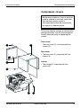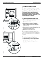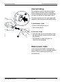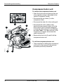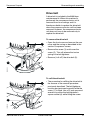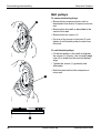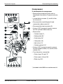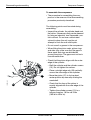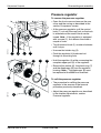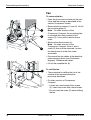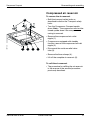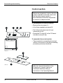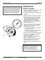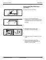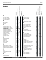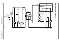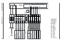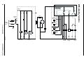
1
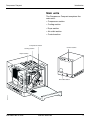
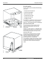
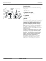
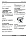
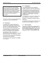
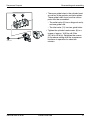
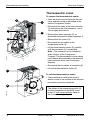
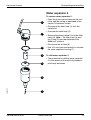
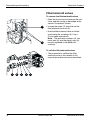
Compressor Compact
Service Manual
E382 EH81E 061 01 03 02
Important
Compressor Compact
Important
General information
Classification
The documentation for the Compressor Compact
consists of:
• Class I equipment.
• Operating Manual
•
according to IEC 601-1.
Type B
• Service Manual
• Spare Parts List
For proper servicing, the Operating Manual and
the Spare Parts List are indispensable
complements to this Service Manual.
Data on pressures in the Compressor Compact
are given in Pa (bar):
1 kPa = 10 mbar
1 kPa = 0.01 bar
1 kPa ≈ 10 cm H2O
1 kPa ≈ 0.01 at
1 kPa ≈ 0.01 kgf/cm2
1 kPa ≈ 0.01 kp/cm2
1 kPa ≈ 0.145 psi
1 mbar = 0.1 kPa
1 bar = 100 kPa
1 cm H2O ≈ 0.1 kPa
1 at ≈ 100 kPa
1 kgf/cm2 ≈ 100 kPa
1 kp/cm2 ≈ 100 kPa
1 psi ≈ 6.9 kPa
In addition to the Important information given
here, always pay attention to applicable national
regulations.
If not stated otherwise in this manual:
• The 100 V/50 Hz, 100 V/60 Hz and 115 V/60 Hz
versions are refered to as the 115 V version.
• The 230 V/50 Hz and 240 V/60 Hz versions are
refered to as the 230 V version.
Hazard notices
The Compressor Compact operates from mains
power supply. With power connected to the unit,
there are energized electrical components as well
as moving mechanical parts inside the equipment.
All personnel must exercise extreme caution when
in the vicinity of this equipment if fault tracing or
adjustments are performed with mains power
supply connected and with the compressor cover
or front panel opened or removed.
The Compressor Compact generates compressed
air at a pressure of 400 kPa (4.0 bar). Do not
attempt to connect or disconnect the compressed
air line or service the compressor section while
compressed air is being supplied. Do not direct
the compressed air line toward the eyes or directly
onto unprotected skin surfaces.
2
Functional check
After any service intervention in the Compressor
Compact, perform a functional check according to
the instructions in the Operating Manual.
Service
Your local Siemens representative supplies the
spare parts indicated in the Spare Parts List.
When ordering spare parts, please state the serial
number of the unit.
The Compressor Compact is oil free, and oil must
not be used when servicing the compressor.
The Compressor Compact must be serviced at
regular intervals as follows:
• 2000 hour overhaul when replacing filters as
described in this Service Manual.
• 8000 hour overhaul as described in this Service
Manual.
To the responsible service personnel
The contents of this document are not binding. If
any significant difference between the product and
this documentation is found, please contact your
local Siemens representative for further
information.
We reserve the right to modify products without
amending this document or advising the user.
We recommend that only Siemens authorized
personnel should be permitted to service or repair
the Compressor Compact, and that only SiemensElema genuine spare parts should be used.
Siemens does not otherwise assume responsibility
for the materials used, the work performed, or any
possible consequences of same.
Siemens-Elema AB
E382 EH81E 061 01 03 02
Contents
Compressor Compact
Page
Page
Important ................................................. 2
Adjustments ............................................. 39
Introduction .............................................. 4
Pressure regulator .............................. 39
General .............................................. 4
Maintenance ............................................ 40
Main units ........................................... 5
General .............................................. 40
Basic principles .................................. 6
Performing the 2000 hour overhaul .... 41
Description of functions ........................... 12
Performing the 8000 hour overhaul .... 42
1. Compressor section........................ 12
Troubleshooting ....................................... 43
2. Cooling section ............................... 14
Index ....................................................... 47
3. Dryer section .................................. 15
Circuit and connection diagrams .............. 48
4. Air outlet section ............................. 19
Without standby function .................... 48
5. Control section ................................ 20
With standby function ......................... 50
Disassembling and assembling ............... 22
Block diagram .......................................... 51
General .............................................. 22
Compressor covers ............................ 23
Transport safety locks ........................ 24
Internal tubing ..................................... 25
Compressor/motor unit ....................... 26
Drive belt ............................................ 27
Belt pulleys ......................................... 28
Compressor ........................................ 29
Thermoelectric cooler ......................... 32
Water separator 2 ............................... 33
Filter solenoid valves .......................... 34
Pressure regulator .............................. 35
Fan ..................................................... 36
Compressed air reservoir ................... 37
Control section ................................... 38
E382 EH81E 061 01 03 02
Siemens-Elema AB
3
Introduction
Compressor Compact
Introduction
General
The Compressor Compact is designed to
supply medical-grade compressed air.
The compressor has a capacity of approx.
40 l/min at a pressure of 400 kPa (4.0 bar).
The Compressor Compact can be placed on
the ventilator cart to form a compact unit
which is easy to move.
The Compressor Compact is well insulated
against noise and therefore does not cause
disturbance when used during operations.
The Compressor Compact is fitted with two
alarms: a temperature alarm that is activated
if the compressor should overheat and a
pressure alarm that is activated if the air
pressure in the compressed air reservoir
drops.
The Compressor Compact is available in a
number of versions each adapted to different
mains power supply and frequence. With the
exception of the ratings of various electrical
components these versions are identical.
The Compressor Compact can be equipped
with a standby function. In the standby
mode, the compressor will start to deliver
compressed air if the hospital central gas
supply fails.
4
Siemens-Elema AB
E382 EH81E 061 01 03 02
Introduction
Compressor Compact
Main units
The Compressor Compact comprises five
main units:
• Compressor section
• Cooling section
• Dryer section
• Air outlet section
• Control section.
Compressor section
Control section
Cooling section
Dryer section
COMP001E
Air outlet section
E382 EH81E 061 01 03 02
Siemens-Elema AB
5
Introduction
Compressor Compact
Basic principles
This text also refers to the Block diagram on
page 53.
Compressor section
The compressor section contains the
following main parts:
Temperature
sensor
Air inlet
silencer
• Air inlet with filter
Motor
Air inlet
with filter
• Air inlet silencer
• Temperature sensor
• Motor
• Drive unit
• Compressor
COMP002E
• Heat convector.
Heat convector
Compressor
Drive unit
The air inlet is supplied with ambient air from
the inside of the dryer section, i.e. air that
has been filtered by the dust filters. This air
then passes through the air inlet with filter
and the air inlet silencer. The air is then
routed to the two-stroke compressor. The
compressor is powered by the electric motor
via the drive unit. The tension of the drive
belt is automatically adjusted.
The action of the compressor imparts heat to
the compressed air. To provide preliminary
cooling, the air flow is passed through the
heat convector before it enters the cooling
section.
The motor, compressor and heat convector
are cooled by the air stream forced through
the compressor section by the fan in the
dryer section. The temperature sensor
detects the ambient air temperature inside
the compressor section and activates the
temperature alarm if the compressor section
is overheated.
6
Siemens-Elema AB
E382 EH81E 061 01 03 02
Introduction
Compressor Compact
Cooling section
COMP003E
Cooling coil
E382 EH81E 061 01 03 02
The main part of the cooling section is the
cooling coil which provides further preliminary
cooling of the compressed air. The compressed air flow, supplied from the compressor
section, passes through the cooling section
via this cooling coil.
The cooling coil is cooled by the air stream
forced through the cooling section by the fan
in the dryer section. This air stream is then
routed to the compressor section.
Siemens-Elema AB
7
Introduction
Compressor Compact
Dryer section
Fuses
Filter / Solenoid
valves
Electric
power supply
The dryer section contains the following
main parts:
• Water separator 1
• Thermoelectric cooler
• Water separator 2
• Filter/solenoid valves
• Drainage bottle
• Standby solenoid valve
Fan
• Low pressure switch
Pressure
regulator
• Standby pressure switch
COMP004E
• Pressure regulator
Electrical
interconnection
• Electric power supply
Dust
filter
• Electrical interconnection
• Fuses
• Dust filters
Thermoelectric cooler
• Fan.
Compressed air, supplied from the cooling
section, passes through water separator 1.
In this “water trap”, some amount of water is
separated from the compressed air.
The air flow then passes through the
thermoelectric cooler where the air
temperature is further lowered. Moisture that
remains in the compressed air is then partly
transformed into water by condensation. This
water is separated from the air in water
separator 2.
Drainage
bottle
Water
separator 2
COMP016E
Water
separator 1
8
Fan
Low
pressure
switch
The dried, compressed air from the air outlet
of water separator 2 is collected in the
compressed air reservoir.
A pressure regulator is connected to the
compressed air tubing. Air pressure in excess
of the preset level on this pressure regulator,
normally approx. 400 kPa (4.0 bar), will
cause a flow which is fed back to the inlet of
the compressor via the air inlet silencer.
Siemens-Elema AB
E382 EH81E 061 01 03 02
Introduction
Compressor Compact
Water separators 1 and 2 are automatically
drained at regular intervals by the two filter/
solenoid valves. The water is collected in the
drainage bottle.
A low pressure switch is connected to the
compressed air reservoir. This switch
(sensor) detects the air pressure inside the
compressed air reservoir and activates the
pressure alarm if the air pressure in the
reservoir drops.
Compressors equipped with the standby
function also include a standby solenoid
valve and a standby pressure switch.
Compressed air from the hospital central gas
supply is connected to the compressed air
reservoir (via the standby solenoid valve). If
the hospital central gas supply fails, the
pressure in the reservoir drops. This air
pressure drop is then detected by the
standby pressure switch and the compressor
starts to deliver compressed air to the
reservoir.
Thermoelectric cooler
Drainage
bottle
Water
separator 1
COMP005E
Water
separator 2
Low
pressure
switch
E382 EH81E 061 01 03 02
Standby
solenoid
valve
Standby
pressure
switch
Fan
The electric power supply functions (transformer, rectifier, capacitors, etc.) are located
in the dryer section. Internal power supply is
distributed from the electrical interconnection
block. The mains power fuses and the
cooling dryer fuse are also situated at the
electrical interconnection block.
The dryer section also contains a fan to
provide forced air cooling in the cooling
section and compressor section. Two dust
filters remove dust particles from the ambient
air before the air is drawn into the fan.
Siemens-Elema AB
9
Compressor Compact
Introduction
Air outlet section
The air outlet section contains the following
main parts:
• Compressed air reservoir
• Pressure manometer
• Moisture relief valve
• Compressed air outlet
• Compressed air inlet
• Cooling air outlet.
COMP006E
The dried air is supplied via water separator 1
in the dryer section to the compressed air
reservoir. The compressed air is available at
the compressed air outlet.
Compressed
air reservoir
Pressure
manometer
Moisture
relief
valve
The air pressure in the compressed air
reservoir is displayed by the pressure
manometer.
If water, for some reason, is collected in the
compressed air reservoir, this water can be
removed by pressing the valve pin of the
moisture relief valve.
Compressors equipped with the standby
function include a compressed air inlet
where the hospital central gas supply
(medical grade air) is connected.
COMP007E
The cooling air stream that has been forced
through the cooling section and compressor
section exits via the silenced cooling air
outlet.
10
Cooling
air outlet
Compressed
air outlet
Compressed
air inlet
Siemens-Elema AB
E382 EH81E 061 01 03 02
Compressor Compact
Introduction
Control section
Electrical
control
function
Indicator lamps
The control section contains the following
main parts:
• On/off switch
Buzzer
• Operating time meter
• Electrical control functions
COMP008E
• Test button
ON/OFF
switch
• Indicator lamps
Operating
time meter
Test button
• Buzzer.
Mains power to the compressor is connected
via and controlled by the on/off switch. The
operating time meter indicates how many
hours the compressor has been running.
Electrical control functions are located on a
PC board in the control section. This PC
board also contains the timing circuit for the
solenoid valves.
There are three indicator lamps (four if the
compressor is equipped with the standby
function). The test button is used to check
that the indicator lamps for temperature
alarm and pressure alarm light up.
The audible alarm (buzzer) is activated
together with the indicator lamp during
temperature alarm and pressure alarm.
E382 EH81E 061 01 03 02
Siemens-Elema AB
11
Description of functions
Compressor Compact
Description of
functions
1.4
Motor
The Compressor Compact is equipped with
a single phase electric MOTOR. The motor
is designed according to IEC 34 standards.
The text in this chapter Description of
functions refers to the:
• Circuit and connection diagrams and Block
diagram on pages 48 – 51.
There are several different versions of the
motor each adapted to different mains power
supply and frequence.
1. Compressor section
The motor is equipped with a thermal switch
that will disconnect the current through the
motor if the motor is overheated.
Air inlet with filter
The AIR INLET WITH FILTER supplies
ambient air from the 3. DRYER SECTION to
the 1.2 SILENCER. The filter is made of a
felt, and must be replaced at the 2000 hour
overhaul as well as at the 8000 hour
overhaul. The filter must not be cleaned in
any liquid.
1.2
Reset
button
Silencer
The air inlet SILENCER will reduce the noise
from the air inlet of the compressor at the
same time as it works as an air distributor to
the two cylinder heads of the 1.6 COMPRESSOR.
1.3
115 V version
The 115 V motor is fitted with a manually
resetable thermal switch. When the motor
has cooled down, the thermal switch must be
reset manually by pushing the reset button
on the motor.
COMP068E
1.1
Temperature sensor
The TEMPERATURE SENSOR detects the
temperature inside the 1. COMPRESSOR
SECTION. If the temperature at this sensor
exceeds 70°C ±3°C (158°F ±5°F), the
temperature alarm is activated.
The temperature alarm is deactivated when
the compressor is switched off or when the
temperature at the sensor drops below
55°C ±6°C (131°F ±11°F).
230 V version
The 230 V motor is fitted with a self-resetting
thermal switch. When the motor cools down,
the thermal switch will automatically restart
the motor.
Note – 230 V versions of the Compressor
Compact as well as spare part motors
manufactured up to and including June 1993
are not equipped with this thermal switch.
The temperature alarm function is further
described in section 5.6 TEMPERATURE
ALARM LAMP.
12
Siemens-Elema AB
E382 EH81E 061 01 03 02
Compressor Compact
Description of functions
1.6
As motors fitted with a self-resetting
termal switch can restart automatically,
all personnel must exercise extreme
caution when in the vicinity of this equipment if fault tracing is performed with
mains power supply connected and with
the compressor cover opened or
removed.
The motion of the motor is transmitted to the
compressor by the 1.5 DRIVE UNIT.
Compressor
The COMPRESSOR is an oil free twincylinder assembly in which the filtered air is
compressed by the action of the twin pistons.
A manifold pipe is connected between the
two cylinder heads so that the compressed
air generated collectively by both pistons is
available at a single outlet on one of the
cylinder heads.
The compressor’s capacity is at least a flow
rate of 40 l/min at a pressure of 400 kPa
(4.0 bar). The compressor speed is approx.
1250 r/min.
A complete overhaul of the compressor must
be performed at the 8000 hour overhaul.
1.5
Drive unit
The DRIVE UNIT transmits the motor's
motion to the compressor. The drive unit
consists of two grooved belt pulleys, a drive
belt and a spring-loaded belt tightener.
The two pulleys are mounted on the motor
shaft and compressor shaft with clamp
bushes (see chapter Disassembling and
assembling for further information).
The transmission ratio is approx. 1 : 2.7 for the
60 Hz motor and 1 : 2.3 for the 50 Hz motor.
1.7
Heat convector
Preliminary cooling of the compressed air is
provided by the HEAT CONVECTOR. This
heat convector is connected to the output of
the 1.6 COMPRESSOR and supplies compressed air to the 2. COOLING SECTION.
The tension of the drive belt is automatically
adjusted by the belt tightener.
The drive belt must be replaced at the 8000
hour overhaul.
E382 EH81E 061 01 03 02
Siemens-Elema AB
13
Description of functions
Compressor Compact
2. Cooling section
3. Dryer section
2.1
3.1
Cooling coil
Water separator 1
A further preliminary cooling of the
compressed air is provided by the COOLING
COIL assembly, which is made of metal
tubing. The compressed air to this cooling
coil is supplied from the 1.7 HEAT CONVECTOR, and the output is connected to 3.1
WATER SEPARATOR 1.
WATER SEPARATOR 1 is a “water trap”
made of a Y-piece connector. This water
separator is connected to the outlet of the
2.1 COOLING COIL, and it supplies
compressed air to the 3.2 THERMOELECTRIC COOLER and to the 3.9 PRESSURE
REGULATOR.
The cooling coil is cooled by the air stream
forced through the cooling section by the fan
in the dryer section. This air stream is then
routed to the compressor section.
The purpose of this water separator is to
collect moisture that has been transformed
into water by condensation when passing
through the cooling section.
The water separator is automatically drained
at regular intervals by one of the two 3.4
FILTER/SOLENOID VALVES, and the water
is collected in the 3.5 DRAINAGE BOTTLE.
WATER SEPARATOR 1 in compressors
with standby function has a different design,
see the chapter Introduction, Dryer section.
The function and purpose of this water
separator is as described above.
3.2
Thermoelectric cooler
The dryer section is equipped with a
THERMOELECTRIC COOLER designed for
12 V DC power supply. The thermoelectric
cooler is a self-contained unit including a
Peltier element which has one cool side and
one warm side.
The compressed air is supplied to the cool
side of the element via 3.1 WATER SEPARATOR 1. When the temperature of the
compressed air is lowered, moisture that
remains in the air is partly transformed into
water by condensation. This water is then
collected in 3.2 WATER SEPARATOR 2
which is connected to the outlet of the
thermoelectric cooler.
The warm side of the Peltier element is
cooled by the air stream provided by the
3.14 FAN.
14
Siemens-Elema AB
E382 EH81E 061 01 03 02
Compressor Compact
Description of functions
A cooler temperature switch (thermostat) is
connected to the Peltier element. The switch
detects the temperature at the cool side of
the element. To avoid formation of ice in the
thermoelectric cooler, this switch will cut the
power supply to the Peltier element if the
temperature drops below approx. +2°C
(+36°F). This thermostat is factory calibrated
and must not be adjusted.
The PC board RCD connected to the thermostat is a spark arrestor. This PC board RCD
is included in the different versions of the
Compressor Compact with standby function
as follows:
• 100 V/50 Hz: Serial No. 50001 or higher.
• 100 V/60 Hz: Serial No. 40001 or higher.
• 115 V/60 Hz: Serial No. 20531 or higher.
3.3
Water separator 2
WATER SEPARATOR 2 is a standard
compressed air filter provided to filter the air
as well as to separate water from the air.
This water separator is connected to the
outlet of the 3.2 THERMOELECTRIC
COOLER, and it supplies compressed air to
the 4.1 COMPRESSED AIR RESERVOIR
(via the 3.6 STANDBY SOLENOID VALVE
in compressors with standby function).
Water separated from the air is collected in
the metal bowl. The water separator is
automatically drained at regular intervals by
one of the two 3.4 FILTER/SOLENOID
VALVES, and the water is collected in the
3.5 DRAINAGE BOTTLE.
Water separator 2 must be overhauled at the
8000 hour overhaul.
• 230 V/50 Hz: Serial No. 30530 or higher.
• 240 V/60 Hz: Serial No. 60013 or higher.
3.4
The PC board RCD must be connected with
correct polarity, refer to the Connection
diagrams.
The two identical FILTER/SOLENOID
VALVES are designed for 12 V DC power
supply. The purpose of these valves is to
remove water collected in 3.1 WATER
SEPARATOR 1 and 3.3 WATER SEPARATOR 2 at regular intervals.
Due to service interventions and recommended updates, the PC board RCD can be
included also in Compressor Compact as
follows:
• Compressor Compact with standby
function with Serial No. lower than stated
in the list above. Exceptions: Units with
Serial No. 126 or lower.
• Compressor Compact 230 V/50 Hz without
standby function. Exceptions: Units with
Serial No. 469 or lower.
Note: A spark arrestor of a different design
(with components mounted onto the cables)
has been installed in the 115 V/60 Hz version
of Compressor Compact with Serial No.:
20498 – 20530. The PC board RCD must
not be installed in these units as long as the
spark arrestor with components mounted
onto the cables is installed.
E382 EH81E 061 01 03 02
Filter/solenoid valves
The electrically controlled solenoid valves
are closed in non-activated condition. During
operation, the solenoid valves will be
activated (open) for approx. 0.5 seconds
twice every minute by the timing circuit in
5.3 ELECTRICAL CONTROL FUNCTIONS.
When the solenoid valves open, the water
collected in the water separators will be
transported to the 3.5 DRAINAGE BOTTLE
via solenoid valves.
The filter/solenoid valves must be
overhauled at the 8000 hour overhaul.
Siemens-Elema AB
15
Description of functions
3.5
Compressor Compact
Drainage bottle
3.7
The DRAINAGE BOTTLE collects the water
that is extracted from the compressed air by
3.1 WATER SEPARATOR 1 and 3.3 WATER
SEPARATOR 2. It is a plastic container with
a screw cap into which the water hose from
the water separators is connected. There is
a ventilation hole in the cap.
3.6
Standby solenoid valve
Compressors with standby function are
equipped with a STANDBY SOLENOID
VALVE. This is an electrically controlled
three-port valve with the following function:
1.If the air pressure in the hospital central
gas supply, connected to the 4.5 COMPRESSED AIR INLET, is above approx.
300 kPa (3.0 bar), the standby solenoid
valve connects this inlet with the 4.1
COMPRESSED AIR RESERVOIR. The
compressor is not active.
2.If the air pressure in the hospital central
gas supply, connected to the 4.5 COMPRESSED AIR INLET, drops and stays
below approx. 300 kPa (3.0 bar) for a few
seconds, the standby solenoid valve
connects the 3.1 WATER SEPARATOR 2
with the 4.1 COMPRESSED AIR
RESERVOIR. The compressor starts to
supply compressed air to the reservoir.
Low pressure switch
The LOW PRESSURE SWITCH is
connected to the 4.1 COMPRESSED AIR
RESERVOIR. This switch will activate the
pressure alarm if the air pressure in the
reservoir drops and stays below 280 kPa
(2.8 bar) for more than 10 seconds.
The pressure alarm is deactivated when the
compressor is switched off or when the
pressure in the reservoir rises above approx.
280 kPa (2.8 bar).
The pressure alarm function is further
described in section 5.8 PRESSURE
ALARM LAMP.
3.8
Standby pressure switch
Compressors with standby function are
equipped with a STANDBY PRESSURE
SWITCH. This switch will start the
compressor if the air pressure in the 4.1
COMPRESSED AIR RESERVOIR (supplied
by the hospital central gas supply via the 4.5
COMPRESSED AIR INLET) drops and stays
below 300 kPa (3.0 bar) for a few seconds.
The switch will also set the 3.6 STANDBY
SOLENOID VALVE to supply gas from the
1.6 COMPRESSOR.
The standby function is further described in
section 5.7 STANDBY LAMP.
The standby solenoid valve is controlled by
the 3.8 STANDBY PRESSURE SWITCH
via the 5.3 ELECTRICAL CONTROL
FUNCTIONS.
The standby function is further described in
section 5.7 STANDBY LAMP.
16
Siemens-Elema AB
E382 EH81E 061 01 03 02
Compressor Compact
3.9
Description of functions
Pressure regulator
The compressed air supply is tapped off at a
three-port coupling at the thermoelectric
cooler-inlet and applied to the PRESSURE
REGULATOR. This device is actually a relief
valve.
Pressure in excess of the set level, normally
approx. 400 kPa (4.0 bar), opens this relief
valve. The excess compressed air flow is
returned to the inlet of the 1.6 COMPRESSOR via the 1.2 SILENCER. This arrangement effectively silences the outlet of this
relief valve.
For pressure adjustment, see the chapter
Adjustments.
The pressure regulator must be overhauled
at the 8000 hour overhaul.
3.10 Electric power supply
The ELECTRIC POWER SUPPLY is a
collective name for some of the parts
included in the power supply to the different
electrical components in the compressor.
Mains power (115 or 230 V AC) is connected
to the on/off switch (via the mains power
fuses) and from here distributed to the:
• Operating time meter
The transformer used in the compressor is a
toroid transformer. There are two different
versions of the transformer, one for 115 V
mains power supply and one for 230 V
mains power supply. The output is 12 V and
max power consumption is 100 VA for both
transformers.
Transformers with serial number extention
-0017 are fitted with a self-resetting thermal
switch that will disconnect the current through
the transformer if it is overheated. When the
transformer cools down, the thermal switch
will automatically reconnect the current
through the transformer.
As transformers fitted with termal switch
can reconnect automatically, all personnel
must exercise extreme caution when in
the vicinity of this equipment if fault tracing
is performed with mains power supply
connected and with the compressor cover
opened or removed.
The compressor is equipped with a rectifier
that is supplied with 12 V AC from the
transformer. The rectifier consists of a
rectifier bridge assembled as a complete,
exchangable unit.
The rectifer smoothing capacitor used is
rated 24 V, 22 000 µF.
• Fan
• Compressor motor
3.11 Electrical interconnection
• Transformer.
All other electrical components are supplied
with 12 V DC.
The main parts in the ELECTRIC POWER
SUPPLY block are the:
The different electrical components are
connected to the ELECTRICAL INTERCONNECTION terminal. The three fuses
mentioned in the description of 3.12 FUSES
are located in this terminal block.
• Transformer
• Rectifier with capacitor
• Start relay (compressors with standby
function).
E382 EH81E 061 01 03 02
Siemens-Elema AB
17
Description of functions
Compressor Compact
3.12 Fuses
3.13 Dust filters
The compressor is equipped with three
FUSES: two mains power fuses (F1 and F2)
and one fuse for the 12 V power supply (F3).
The fuses are located in the 3.11 ELECTRICAL INTERCONNECTION block.
There are two DUST FILTERS mounted on
the compressor housing. These two identical
filters are made of a synthetic material.
F1 / F2
F3
They must be regularly inspected and
cleaned as described in the Operating
Manual, chapter Cleaning. The filters must
be replaced at the 2000 hour overhaul as
well as at the 8000 hour overhaul.
3.14 Fan
The Compressor Compact is equipped with
a double inlet centrifugal FAN. The purpose
of the fan is to provide forced air cooling for
the 1. COMPRESSOR SECTION and the
2. COOLING SECTION.
There are two different versions of the fan,
one for 115 V mains power supply and one
for 230 V mains power supply.
COMP045X
Fuse No. Type No.
Manufacturer Dimension
The fan motor is fitted with a self-resetting
thermal switch that will cut the power supply
to the fan motor if the temperature at the
switch exceeds approx. 130°C (266°F).
115 V versions
Mains power fuses:
F1/F2
MDA 10A 250V Bussman
6.3 x 32
12 V power fuse:
F3
MDA 15A 250V Bussman
6.3 x 32
230 V versions
Mains power fuses:
F1/F2
T 6.3AL
12 V power fuse:
F3
T 10AL 250V
–
5 x 20
Littelfuse
5 x 20
When replacing fuses in the Compressor
Compact, make sure to use fuses as stated
above (Type No. and Manufacturer).
If the compressor is connected to mains
power, there is live voltage at the mains
power fuses even when the on/off switch
is in OFF (0) position.
18
Siemens-Elema AB
E382 EH81E 061 01 03 02
Compressor Compact
Description of functions
4. Air outlet section
4.1
Compressed air reservoir
The COMPRESSED AIR RESERVOIR is a
plastic container with a volume of approx.
1.8 liters.
4.2
Pressure manometer
A PRESSURE MANOMETER is connected
to the 4.1 COMPRESSED AIR RESERVOIR.
This manometer shows the air pressure in
the reservoir. The manometer has the range:
• 0 – 6 bar in older versions of the
Compressor Compact.
• 0 – 10 bar in newer versions of the
Compressor Compact.
4.3
When testing the Compressor Compact, the
test nozzle should be connected to this outlet
so that compressed air flows through the
nozzle. Output pressure can then be read off
from the pressure manometer.
The test nozzle permits an air flow that is
higher than 40 l/min. For this reason the air
pressure in the system may not reach the
stated 400 kPa (4 bar) when the test nozzle
is connected. An air pressure of 400 kPa
±50 kPa (4.0 bar ±0.5 bar) indicated on the
manometer shows that the compressor is
operating correctly.
4.5
Compressed air inlet
Compressors with standby function are
equipped with a COMPRESSED AIR INLET.
Moisture relief valve
The MOISTURE RELIEF VALVE is
connected to the bottom of the 4.1 COMPRESSED AIR RESERVOIR with a plastic
tube. This valve is a spring-loaded valve that
is provided to drain the air reservoir if water,
for some reason, collects in the reservoir.
The valve pin must be pushed manually to
drain the air reservoir.
This air inlet is connected to the 4.1 COMPRESSED AIR RESERVOIR via the
3.6 STANDBY SOLENOID VALVE. The
purpose of the air inlet is to provide compressed medical grade air from the hospital
central gas supply to the air reservoir.
The inlet nipple must be adapted to local
standards. The inlet hole in the reservoir is
provided with a 12 x 1 mm thread.
The standby function is further described in
section 5.7 STANDBY LAMP.
4.4
Compressed air outlet
The COMPRESSED AIR OUTLET is
connected directly to the 4.1 COMPRESSED
AIR RESERVOIR. It consists of a female
(AGA standard) quick-coupling and a hose
nipple for an 8 mm hose.
The test nozzle attached to the compressor
must be used when performing functional
checks or troubleshooting on the
Compressor Compact. It provides a
simulated load that permits rapid, easy
checks of the output pressure.
E382 EH81E 061 01 03 02
4.6
Cooling air outlet
The forced cooling air stream provided by
the 3.14 FAN in the dryer section exits from
the compressor via the COOLING AIR
OUTLET. The air outlet is covered with foam
rubber to reduce the noise of the air stream.
Siemens-Elema AB
19
Description of functions
Compressor Compact
5. Control section
5.4
5.1
The purpose of the TEST BUTTON is to
make it possible to check the alarm indicator
lamps and the audible alarm.
On/off switch
The ON/OFF SWITCH is the switch for mains
power supply to the compressor. Mains
power is connected to the mains power
fuses in the 3.11 ELECTRICAL INTERCONNECTION terminal and then routed, via
internal cabling, to the on/off switch.
5.2
The OPERATING TIME METER shows the
cumulative total of the number of hours that
the Compressor Compact has been in
operation. The range of the meter is 1/100 of
an hour up to 10,000 hours and it cannot be
reset to zero.
5.3
When this button is held depressed, the
indicator lamps for temperature alarm and
pressure alarm will light up. The audible
alarm buzzer will also be activated.
5.5
Operating time meter
Electrical control functions
The ELECTRICAL CONTROL FUNCTIONS
are located on a PC board in the control
section. This PC board controls the:
• Temperature alarm and pressure alarm
• Timing circuits for the solenoid valves 1
and 2 including RL2
• Standby functions including RL1 and RL3.
Test button
Mains power lamp
The green MAINS POWER LAMP is supplied
from the 12 V DC circuit. This means that the
mains power lamp indicates that mains
power as well as 12 V power is on.
5.6
Temperature alarm lamp
The temperature alarm is activated if the air
temperature at the 1.3 TEMPERATURE
SENSOR exceeds 70°C ±3°C (158°F ±5°F).
This alarm is indicated by the red TEMPERATURE ALARM LAMP and the ALARM
BUZZER.
The alarm lamp will stay on until the alarm is
deactivated.
The temperature alarm is deactivated at a
temperature below 55°C ±6°C (131°F ±11°F).
The test button, the indicator lamps and the
buzzer are mounted on this PC board.
20
Siemens-Elema AB
E382 EH81E 061 01 03 02
Compressor Compact
5.7
Description of functions
Standby lamp
The yellow STANDBY LAMP will be on only
when the compressor is in standby mode,
i. e. when the 4.1 COMPRESSED AIR
RESERVOIR is supplied with compressed
air from the hospital central gas supply.
The standby function can be described as
follows:
1.With the compressor switched off, connect
compressed medical grade air from the
hospital central gas supply to the 4.5
COMPRESSED AIR INLET. The gas
pressure must be above approx. 300 kPa
(3.0 bar). Switch on the compressor:
– The 3.8 STANDBY PRESSURE SWITCH
detects that the pressure in the reservoir
is above approx 300 kPa (3.0 bar)
– The STANDBY LAMP lights up
– The 3.6 STANDBY SOLENOID VALVE
is automatically set to supply compressed
air from the central gas supply to the
4.1 COMPRESSED AIR RESERVOIR
– The compressor motor is not on, i. e. the
compressor is not active.
2.The compressed air from the central gas
supply is disconnected or the pressure
drops below approx. 300 kPa (3.0 bar):
The compressor will not automatically return
to standby mode if the pressure in the
central gas supply returns.
5.8
Pressure alarm lamp
The pressure alarm is activated if the air
pressure in the 4.1 COMPRESSED AIR
RESERVOIR, detected by the 3.7 LOW
PRESSURE SWITCH, drops and stays
below 280 kPa (2.8 bar) for 10 seconds. This
alarm is indicated by the red PRESSURE
ALARM LAMP and the ALARM BUZZER.
The alarm lamp and the alarm buzzer will
stay on until the alarm is deactivated or until
the compressor is switched off.
The pressure alarm is deactivated when the
air pressure rises above approx. 280 kPa
(2.8 bar).
5.9
Buzzer
The alarm BUZZER gives an audible alarm
indication. The buzzer is active:
• During the first 10 seconds of a temperature alarm
• During a pressure alarm
• When the 5.4 TEST BUTTON is depressed.
– The 3.8 STANDBY PRESSURE SWITCH
detects that the pressure in the reservoir
drops and stays below approx. 300 kPa
(3.0 bar) for a few seconds
– The start relay RL4 connects mains
power to the compressor motor. The
compressor starts to work, i. e. the
compressor supplies compressed air
– The 3.6 STANDBY SOLENOID VALVE
is automatically set to supply compressed
air from the compressor to the 4.1 COMPRESSED AIR RESERVOIR
– The STANDBY LAMP goes off.
E382 EH81E 061 01 03 02
Siemens-Elema AB
21
Disassembling and assembling
Compressor Compact
Before any compressor cover or the front
panel is opened or removed, make sure
that the mains power supply is
disconnected and that the compressed
air reservoir is depressurized.
With mains power supply connected to
the unit, there are energized electrical
components as well as moving
mechanical parts inside the equipment.
All personnel must exercise extreme
caution when in the vicinity of this
equipment if fault tracing or adjustments
are performed with mains power supply
connected and with the compressor
cover or front panel opened or removed.
After any service intervention in the
Compressor Compact, perform a
Functional check according to
instructions in the Operating Manual.
Disassembling and
assembling
General
• This chapter describes disassembling and
assembling of some of the main parts of
the Compressor Compact. The drawings in
the Spare Parts List are also useful as a
guide when disassembling and assembling
the Compressor Compact.
• To avoid the possible spillage of water,
before disassembling the Compressor
Compact run the unit until the solenoid
valves in the dryer section operate to drain
water into the drainage bottle. Then
remove the drainage bottle, empty the
bottle and refit it.
• Wait for the Compressor Compact to cool
down before proceeding.
• Locking or sealing compounds are used on
many of the screwed connections. Detailed
information can be found in the Spare
Parts List. Old locking and sealing
compound must be removed and the
threads must be cleaned before any new
compound is applied.
22
Siemens-Elema AB
E382 EH81E 061 01 03 02
Compressor Compact
Disassembling and assembling
Compressor covers
Before any compressor cover or the front
panel is opened or removed, make sure
that the mains power supply is
disconnected and that the compressed
air reservoir is depressurized.
The covers and the casing are secured with
hexagonal screws. Use a 5 mm hexagonal
wrench when removing or tightening the
screws.
Front cover
4
• The front cover (1) is secured with two
screws (2).
5
Rear cover
• The rear cover (3) is secured with four
screws (4).
Casing
3
• The casing (5) is secured with four
screws (6).
COMP009X
6
E382 EH81E 061 01 03 02
1
2
Siemens-Elema AB
23
Disassembling and assembling
Compressor Compact
Transport safety locks
To secure the compressor/motor unit and
thereby prevent damage during transit of the
Compressor Compact or when the Compressor Compact is turned upside down, the
unit must be fixed to the base with two
transport safety locks. When the transport
safety locks are removed, the tension in the
vibration dampers is released.
To remove the transport safety locks
• Open the front cover and remove the rear
cover as described in the section
Compressor covers.
1
COMP010X
3
• Remove the two screws (1) and the
screw (2) and lift off the front transport
safety lock (3).
• Remove the two screws (4) and lift off the
rear transport safety lock (5).
2
• Refit the front and rear covers.
Do not discard the transport safety locks.
They must be mounted on the compressor/
motor unit during transit of the Compressor
Compact.
To refit the transport safety locks
• The procedure for refitting the transport
safety locks is the reverse of the
disassembling procedure previously
described.
4
COMP011X
5
24
Siemens-Elema AB
E382 EH81E 061 01 03 02
Compressor Compact
Disassembling and assembling
Internal tubing
1
The couplings used for the internal tubing
(nylon tubes) are quick-action couplings.
These couplings are used for compressed
air tubes as well as for drain water tubes.
The tubes must be cut at a right angle and
the ends of the tubes must be without burrs.
To disconnect a tube
• Push in and hold the ring (1).
• Pull out the tube (2).
COMP037X
To connect a tube
2
• Push the tube (2) into the coupling. Push
the tube forcefully toward the stop inside
the coupling.
• Pull the tube to make sure that it is
secured to the coupling.
Mains power cable
If the mains power cable is replaced, the
three conductors must be strapped together
close to their connecting points at the
terminal block.
E382 EH81E 061 01 03 02
Siemens-Elema AB
25
Disassembling and assembling
Compressor Compact
Compressor/motor unit
To remove the compressor/motor unit
• Open the front cover and remove the rear
cover and the casing as described in the
section Compressor covers.
• Disconnect the two tubes (1) at the
compressor inlets.
• Disconnect the tube (2) at the cooling coil.
3
• Disconnect the motor cables at the
electrical interconnection block (4) in the
dryer section (see Connection diagram).
Loosen the cable sleeve (5) and withdraw
the cable. Note – On older versions of the
Compressor Compact, disconnect the
cable connector (3).
2
4
1
• Remove the four nuts (6) and lift off the
compressor/motor unit.
To refit the compressor/motor unit
COMP012X
6
26
5
• The procedure for refitting the compressor/
motor unit is the reverse of the removal
procedure previously described.
1
Siemens-Elema AB
E382 EH81E 061 01 03 02
Compressor Compact
Disassembling and assembling
Drive belt
A drive belt is included in the 8000 hour
maintenance kit. When this overhaul is
performed, the compressor/motor unit is
removed from its mountings and it is
therefore suitable to replace the drive belt
when the compressor/motor unit has been
removed. However, the compressor/motor
unit does not have to be removed only to
replace the drive belt.
To remove the drive belt
1
• Open the front cover and remove the rear
cover and the casing as described in the
section Compressor covers.
• Remove the screw (1) and loosen the
screw (2). This will release the torsion
spring in the belt tightener.
• Remove (“roll-off”) the drive belt (3).
3
COMP013X
2
To refit the drive belt
1
• The procedure for refitting the drive belt is
the reverse of the removal procedure
previously described. The belt tightener
must be pre-tensioned manually while the
screw (1) is fitted. Use a 23 mm open-end
wrench to position the belt tightener’s
square socket (4) while fitting the screw.
COMP014X
4
E382 EH81E 061 01 03 02
Siemens-Elema AB
27
Disassembling and assembling
Compressor Compact
Belt pulleys
To remove the belt pulleys
• Remove the compressor/motor unit as
described in the section Compressor/motor
unit.
1
• Remove the drive belt as described in the
section Drive belt.
• Remove the two screws (1).
• Put one of the screws in the hole (2) and
tighten it until the belt pulley loosens from
the shaft.
To refit the belt pulleys
COMP017X
• Fit the belt pulley on the shaft and tighten
the screws (1) loosely. Use a straight edge
ruler (3) to check that the two belt pulleys
align.
• Tighten the screws (1) gradually and
alternately.
• Refit the drive belt and the compressor/
motor unit.
COMP022X
COMP018X
2
28
3
Siemens-Elema AB
E382 EH81E 061 01 03 02
Compressor Compact
Disassembling and assembling
Compressor
To disassemble the compressor
8
9
10
11
• Remove the compressor/motor unit as
described in the section Compressor/motor
unit.
12
• Loosen the four screws (1) and lift off the
fan shroud (2).
13
• Disconnect the manifold pipe (3) and
remove the rubber seals (4)*.
• Disconnect the heat convector (5).
6
14
7
• Using a 3/16" hexagonal wrench, remove
the four cylinder head screws (6).
• Remove the:
– Cylinder head (7)
2
– Head gasket (8)*
1
5
– Outlet valve (9)*
3
– Valve plate (10)
4
– Inlet valve (11)*
– Cylinder gasket (12)*.
• Using a 3/16" hexagonal wrench, remove
the two cylinder screws (13) and lift off the
cylinder (14)
• From the piston, remove the:
– Piston rings (15 and 17)*
– Piston seals (16 and 18)*
COMP015X
– Rider ring (19)*.
15
16
17
18
19
*) Included in the 8000 hour maintenance kit.
E382 EH81E 061 01 03 02
Siemens-Elema AB
29
Disassembling and assembling
Compressor Compact
To assemble the compressor
• The procedure for assembling the compressor is the reverse of the disassembling
procedure previously described.
The following points must be noted during
assembling:
• Inspect the cylinder, the cylinder head and
the piston. If necessary they can be cleaned
by using an industrial, non-flammable, nontoxic solvent. Do not use a chlorinated
solvent to clean the unit, and do not
attempt to flush the unit with liquids.
• Do not use oil or grease in the compressor.
• When fitting the piston seals, piston rings
and rider ring, make sure that the gaps in
these seals and rings are distributed
around the piston. The gaps must not be in
line with each other.
• Check that the piston aligns with the outer
edge of the cylinder:
21
– Refit the cylinder and the cylinder screws
(13). Do not tighten the screws.
– Place a straight edge rule (20) vertically
across the outer edge of the cylinder.
COMP023X
13
20
– Move the piston (21) to its top dead
center position by manually rotating the
crankshaft.
– Check that the face of the piston is
exactly aligned with the outer edge of the
cylinder.
– Tighten the cylinder screws (13) to a
torque of approx. 18 Nm ±0.5 Nm
(165 lbf in ±5 lbf in).
30
Siemens-Elema AB
E382 EH81E 061 01 03 02
Compressor Compact
9
11
Disassembling and assembling
• There are guide holes in the cylinder head
as well as in the gaskets and valve plates.
These guide holes show how the various
parts must be assembled:
– The outlet valve (9) has a diagonal cavity
and one guide hole.
– The inlet valve (11) has two guide holes.
6
COMP024X
E382 EH81E 061 01 03 02
• Tighten the cylinder head screws (6) to a
torque of approx. 10.5 Nm ±0.5 Nm
(95 lbf in ±5 lbf in). Retighten the screws
to the above setting after the compressor
has been in operation for about ten
minutes.
Siemens-Elema AB
31
Disassembling and assembling
Compressor Compact
Thermoelectric cooler
To remove the thermoelectric cooler
3
4
• Disconnect the tubes at the inlet connector
(1) and remove the inlet connector. Use a
14 mm open-end wrench.
1
5
2
• Open the front cover and remove the rear
cover and the casing as described in the
section Compressor covers.
• Remove the water separator (2) as
described in the section Water separator 2.
• Remove the two screws (3).
COMP025X
• Disconnect the two cables at the
temperature switch (4).
• Lift the thermoelectric cooler (5) carefully
until the connector (6) is accessible.
Note – This connector is not included in
older versions of the Compressor
Compact. The thermoelectric cooler cables
must then be disconnected at the electrical
interconnection block (see Connection
diagram).
• Disconnect the two cables at connector (6).
• Lift off the thermoelectric cooler (5).
7
To refit the thermoelectric cooler
• The procedure for refitting the thermoelectric cooler is the reverse of the removal
procedure previously described.
COMP026X
6
32
The cables to the temperature switch (4)
must be connected via the RCD circuit
board (7) with correct polarity. Refer to
the Connection diagrams.
Siemens-Elema AB
E382 EH81E 061 01 03 02
Compressor Compact
Disassembling and assembling
Water separator 2
To remove water separator 2
6
• Open the front cover and remove the rear
cover and the casing as described in the
section Compressor covers.
• Disconnect the water tube (1) from the
metal bowl.
• Unscrew the metal bowl (2).
7
• Remove the plastic shield (3) and the filter
insert (4). Note – The filter insert (4) and
the O-ring (5) must be replaced at the
8000 hour overhaul.
• Disconnect the air tube (6).
5
• Use a 14 mm open-end wrench to unscrew
the water separator housing (7).
4
To refit water separator 2
3
• The procedure for refitting water separator
2 is the reverse of the removal procedure
previously described.
COMP027X
2
E382 EH81E 061 01 03 02
1
Siemens-Elema AB
33
Disassembling and assembling
Compressor Compact
Filter/solenoid valves
To remove the filter/solenoid valves
• Open the front cover and remove the rear
cover and the casing as described in the
section Compressor covers.
COMP019X
1
2
• Loosen the screw (1) and slide out the
filter/solenoid valve unit (2).
• Hold the filter/solenoid valve unit while
unscrewing the couplings (3). Use a
21 mm open-end wrench.
Note – The restriction washers (4), the
mesh nets (5) and the plastic rings (6)
must be replaced at the 8000 hour
overhaul.
To refit the filter/solenoid valves
COMP028X
• The procedure for refitting the filter/
solenoid valves is the reverse of the
removal procedure previously described.
34
3
6
5
4
6
Siemens-Elema AB
E382 EH81E 061 01 03 02
Compressor Compact
Disassembling and assembling
Pressure regulator
To remove the pressure regulator
• Open the front cover and remove the rear
cover and the casing as described in the
section Compressor covers.
• At the pressure regulator, pull the control
knob (1) out until the snap lock on the knob
is released and the control knob can be
turned. Note – If the regulator is equipped
with a screw (2), first release the screw a
couple of turns.
COMP029X
• Turn the control knob (1) counter-clockwise
until it stops.
• Unscrew the holder ring (3).
4
3
1
2
• Push the regulator (4) backward out
through its mounting hole.
8
7
6
• Hold the regulator (4) while unscrewing the
complete upper part (5) of the regulator.
• Remove the washer (6), the plastic ring (7)
and the diaphragm (8) from the regulator
housing. Note – The diaphragm (8) must
be replaced at the 8000 hour overhaul.
4
To refit the pressure regulator
COMP030X
• The procedure for refitting the pressure
regulator is the reverse of the removal
procedure previously described.
5
E382 EH81E 061 01 03 02
• Adjust the pressure regulator as described
in the chapter Adjustments, section
Pressure regulator.
Siemens-Elema AB
35
Disassembling and assembling
Compressor Compact
Fan
To remove the fan
• Open the front cover and remove the rear
cover and the casing as described in the
section Compressor covers.
1
COMP031X
3
4
2
• Remove the four screws (1) and (2). Lift off
the mounting plate (3).
Note – On older versions of the
Compressor Compact, the mounting plate
is mounted with rivets instead of the
screws (2). Use a drill to remove these
rivets.
• Remove the three screws (4).
Note – On older versions of the
Compressor Compact, there is also a
screw (5) that must be removed. Loosen
the transformer to make this screw
accessible.
• Disconnect the fan cables at the electrical
interconnection block (see Connection
diagram). Withdraw the cables.
• Lift off the complete fan (6).
5
To refit the fan
COMP032X
• The procedure for refitting the fan is the
reverse of the removal procedure
previously described.
• On older versions of Compressor
Compact:
4
– If rivets are used insted of the screws
(2), insert new rivets with a hand riveter.
– Do not insert the screw (5) when refitting
the fan.
36
Siemens-Elema AB
E382 EH81E 061 01 03 02
Compressor Compact
Disassembling and assembling
Compressed air reservoir
To remove the air reservoir
• Refit the transport safety locks as
described in section the Transport safety
locks.
4
• Turn the Compressor Compact upside
down. Note – The compressor must not be
turned upside down if the compressor
casing is removed.
COMP033X
• Remove the compressed air outlet
nipple (1).
• Compressors equipped with standby
function: remove the compressed air inlet
nipple (2).
3
1
2
5
• Disconnect the moisture relief valve
tube (3).
• Remove the three clamps (4).
• Lift off the complete air reservoir (5).
To refit the air reservoir
• The procedure for refitting the air reservoir
is the reverse of the removal procedure
previously described.
E382 EH81E 061 01 03 02
Siemens-Elema AB
37
Disassembling and assembling
Compressor Compact
Control section
Before any compressor cover or the front
panel is opened or removed, make sure
that the mains power supply is
disconnected and that the compressed
air reservoir is depressurized.
To disassemble the control section
• Remove the six screws (1).
2
1
3
• Lift off the complete front panel (2).
4
• Pull off the test button knob (3) and
remove the nut (4).
0
1
0
0
STAND
BY
TEST
t
1
kPa
• Grasp the PC board (5) at the PC board
connector and pull it up.
1
To assemble the control section
• The procedure for assembling the control
section is the reverse of the disassembling
procedure previously described.
COMP034X
5
COMP035X
2
After any service intervention in the
Compressor Compact, perform a
Functional check according to
instructions in the Operating Manual.
38
Siemens-Elema AB
E382 EH81E 061 01 03 02
Compressor Compact
Adjustments
This adjustment is performed with mains
power connected and energized electrical
components as well as moving mechanical parts in the Compressor Compact.
All personnel must exercise extreme
caution when in the vicinity of the unit.
Adjustments
Pressure regulator
• Open the compressor’s front cover to make
the pressure regulator accessible.
• Connect the test nozzle to the compressed
air outlet.
• Start the compressor with the on/off switch.
• At the pressure regulator, pull the control
knob out until the snap lock on the knob is
released and the control knob can be
turned freely. Note – If the regulator is
equipped with a screw (1), first release the
screw a couple of turns.
3
2
4
1
5
0
bar
6
• Turn the control knob until the manometer
indicates an output pressure of 400 kPa
±50 kPa (4.0 bar ±0.5 bar):
– To increase the pressure, turn the knob
in a clockwise direction.
COMP036X
– To decrease the pressure, turn the knob
in a counter-clockwise direction.
1
+
• Push in the control knob until the snap lock
on the knob is engaged and the control
knob cannot be turned.
Note – If the regulator is equipped with a
screw (1), tighten the screw.
• Switch off the compressor with the on/off
switch and remove the test nozzle.
• Close and secure the compressor’s front
cover.
After any service intervention in the
Compressor Compact, perform a
Functional check according to
instructions in the Operating Manual.
E382 EH81E 061 01 03 02
Siemens-Elema AB
39
Maintenance
Compressor Compact
Maintenance
General
The Compressor Compact must be serviced
at regular intervals as follows:
• 2000 hour overhaul when replacing filters
according to this chapter.
• 8000 hour overhaul according to this
chapter.
The filters that must be replaced during the
2000 hour overhaul are supplied in the Set of
filters for Compressor Compact.
The 8000 hour overhaul requires disassembly of the Compressor Compact.
The following parts must be replaced and
new parts are supplied in the Maintenance
kit for Compressor Compact:
• Inlet and outlet valves, cylinder and head
gaskets, piston rings, piston seals and
rider rings in the compressor
• Rubber seals in the manifold pipe
• Drive belt
• O-ring and filter insert in water separator 2
• Restriction washers, mesh nets and plastic
rings for the filter/solenoid valves
• Pressure regulator diaphragm
• Air inlet filter
• Dust filters.
Also inspect air tubings, electrical
connections and wiring, etc, when the
Compressor Compact is disassembled.
Before any compressor cover or the front
panel is opened or removed, make sure
that the mains power supply is
disconnected and that the compressed
air reservoir is depressurized.
40
Siemens-Elema AB
E382 EH81E 061 01 03 02
Compressor Compact
Maintenance
Performing the 2000 hour
overhaul
COMP065X
1. Replace the two dust filters.
COMP066X
2. Using a 5 mm hexagonal wrench,
unscrew the two screws holding the front
cover and open the cover to access the
inlet filter.
COMP067X
3. Replace the filter located in the
compressor inlet filter housing.
4. Close and secure the compressor's front
cover.
5. Perform a functional check. See
instructions in the Operating Manual,
chapter Functional check.
E382 EH81E 061 01 03 02
Siemens-Elema AB
41
Maintenance
Compressor Compact
Performing the 8000 hour
overhaul
1. Replace inlet and outlet valves, cylinder
and head gaskets, piston rings, piston
seals and rider rings in the compressor.
Also replace the rubber seals in the
manifold pipe. See instructions in the
chapter Disassembling and assembling,
section Compressor.
2. Replace the drive belt. See instructions in
the chapter Disassembling and assembling, section Drive belt.
3. Replace the O-ring and filter insert in
water separator 2. See instructions in the
chapter Disassembling and assembling,
section Water separator 2.
4. Replace the restriction washers, mesh
nets and plastic rings in the two filter/
solenoid valves. See instructions in the
chapter Disassembling and assembling,
section Filter/solenoid valves.
5. Replace the pressure regulator
diaphragm. See instructions in the chapter
Disassembling and assembling, section
Pressure regulator.
6. Replace the air inlet filter and the dust
filters. See section ”Performing the 2000
hour overhaul” in this chapter.
7. Inside the Compressor Compact, inspect
air tubing and electrical wiring with
connections. Tighten any loose connections and replace any item that is
damaged.
8. Adjust the pressure regulator as
described in the chapter Adjustments.
9. Perform a functional check. See
instructions in the Operating Manual,
chapter Functional check.
42
Siemens-Elema AB
E382 EH81E 061 01 03 02
Compressor Compact
Troubleshooting
Troubleshooting
Before you start any troubleshooting, begin if
possible by questioning the person reporting
the fault. Ask how the fault appeared.
Make sure that there has been no operating
error. For this purpose, see also the chapter
Troubleshooting in the Operating Manual.
There should be a logical trend to your
troubleshooting. First try to trace the faulty
function. Then the most suitable procedure is
to track down the exact fault by
systematically replacing individual parts, one
at a time.
One purpose of the Description of functions,
the Circuit and connection diagrams, and the
Block diagram in this Service Manual is to
make it easier to trace faults.
With mains power supply connected to
the unit, there are energized electrical
components as well as moving
mechanical parts inside the equipment.
All personnel must exercise extreme
caution when in the vicinity of this
equipment if fault tracing or adjustments
are performed with mains power supply
connected and with the compressor
cover or front panel opened or removed.
Malfunction
Action
The compressor will not start; the mains
power lamp does not come on:
• Check the mains power supply and mains
fuses.
• Inspect all electrical cables and connectors.
Tighten loose connectors and/or replace
damaged components.
The compressor runs, but the mains power
lamp does not come on:
• Check that there is 12 V DC present. If the
thermal switch in the transformer has
tripped, no 12 V DC is present. Refer to
chapter ”Description of functions” section
”3.10 Electric power supply”.
• Inspect the electrical connections to the
control section PC board. Tighten loose
connectors and/or replace damaged
components.
• Replace the control section PC board.
No compressed air is delivered although the
compressor is running:
• Check the compressed air outlet for
obstruction or damage and replace it if
necessary.
• Inspect the internal compressed air tubing.
Clear obstructions, tighten loose connectors and/or replace faulty components.
• Check the operation of the compressor.
Overhaul or replace it if necessary.
E382 EH81E 061 01 03 02
Siemens-Elema AB
43
Troubleshooting
Compressor Compact
Malfunction
Action
The compressor stops; the mains power
lamp stays on:
• The thermal switch inside the motor may
have tripped.
115 V version: The thermal switch on the
motor must be reset manually.
230 V version: The thermal switch will
reset automatically and the motor will
restart.
Operating pressure (shown on the manometer) is correct during functional check but
drops when a ventilator is connected:
• Too high air consumption. The compressor
cannot supply the equipment connected.
• The dust filters or the air inlet filter are
clogged. Clean or replace the filters if
necessary.
• Check the operation of the compressor.
Overhaul or replace it if necessary.
The pressure alarm is activated:
• Too high air consumption. The compressor
cannot supply the equipment connected.
• Inspect the internal compressed air tubing.
Clear obstructions, tighten loose connectors and/or replace faulty components.
Check of cooler temperature switch
+
+
+
+
-
-
-
-
-
1
2
3
4
5
5
6
7
7
1
2
3
4
5
5
6
7
7
+
+
+
+
-
-
-
-
-
• The dust filters or the air inlet filter are
clogged. Clean or replace the filters if
necessary.
• Pressure alarm function faulty. Replace
low pressure switch and/or control section
PC board if necessary.
• Check the operation of the compressor.
Overhaul or replace it if necessary.
STANDBY SOLENOID V.
START RELAY RL4
RD
THERMOEL. COOLER
FILTER / SOLENOID V.
FILTER / SOLENOID V.
STANDBY PRESS. SW.
LOW PRESS. SWITCH
TEMP. SENSOR
COOLER TEMP. PC
SWITCH
BOARD
(THERMOSTAT) RCD
COMP069E
BK
• The thermoelectric cooler is clogged with
ice due to malfunction in the cooler. Check
the function of the cooler temp. switch:
– Connect a voltmeter between the cooler
connection cables at terminal 6.
– Make sure that the voltage to the cooler
switches between approx. 0 V and 12 V.
Normal switch cycle is approx. 1 min
when no compressed air is consumed.
Replace the cooler if necessary.
44
Siemens-Elema AB
E382 EH81E 061 01 03 02
Compressor Compact
Troubleshooting
Malfunction
Action
The temperature alarm is activated:
• Ambient air temperature is too high.
• The compressor’s ventilation holes are
blocked. Check cooling air inlets as well
as cooling air outlet.
• The dust filters are clogged. Clean or
replace the filters if necessary.
• Check the operation of the fan. Replace it
if necessary.
• Temperature alarm function faulty. Replace
temperature sensor and/or control section
PC board if necessary.
• Check the operation of the compressor.
Overhaul or replace it if necessary.
Abnormal amounts of water flush out through
the moisture relief valve when the valve pin
is depressed:
• Check the operation of water separator 2
and filter/soleniod valves. Overhaul or
replace them if necessary.
• Malfunction in the thermoelectric cooler.
Check the function of the cooler temp.
switch as previously described. Replace
the thermoelectric cooler if necessary.
The manometer does not indicate the correct
operating pressure:
• Inspect the compressed air tubing. Clear
obstructions, tighten loose connectors and/
or exchange faulty components.
• Adjust the pressure regulator as described
in the chapter Adjustments. If the operating
pressure cannot be adjusted, replace the
pressure regulator.
• Check the manometer and replace it if
necessary.
• Check the operation of the compressor.
Overhaul or exchange it if necessary.
E382 EH81E 061 01 03 02
Siemens-Elema AB
45
Troubleshooting
Compressor Compact
Malfunction
Action
Water appears to be leaking from the
Compressor Compact:
• Inspect all water tubes and connectors.
Tighten loose connectors and/or replace
damaged components.
• Inspect the drainage bottle for leaks or a
loose connection. Replace the bottle if
necessary.
• Inspect filter/water separators and replace
them if necessary.
• Inspect solenoid valves and replace them if
necessary.
Water does not accumulate in the drainage
bottle at regular intervals. Drainage is too
frequent, not frequent enough, or does not
occur at all:
• Inspect all water tubes and connectors.
Clear obstructions and/or replace faulty
components.
• Inspect filter/solenoid valves and replace
them if necessary.
• Inspect water separator 2 and replace it if
necessary.
• Replace the control section PC board.
• Malfunction in the thermoelectric cooler.
Check the function of the cooler temp.
switch as previously described. Replace
the thermoelectric cooler if necessary.
The operating time meter does not run when
the Compressor Compact is in operation:
46
• Replace the operating time meter.
Siemens-Elema AB
E382 EH81E 061 01 03 02
Compressor Compact
Indicator lamps
Internal tubing
6
6 12
10 19
Low pressure switch
28
11 21
C
Compressed air inlet
Compressed air outlet
Compressed air reservoir
Compressor
Compressor covers
Compressor section
Compressor/motor unit
Control section
Cooling air outlet
Cooling coil
Cooling section
10
10
10
6
19
19
19 37
13 29
23
6 12
26
11 20 38
10 19
7 14
7 14
D
Drainage bottle
Drive belt
Drive unit
Dryer section
Dust filters
8
16
6
8
8
13
14
18
27
8 17
11 20
8 17
E382 EH81E 061 01 03 02
Adjustments
Disassembling and assembling
Description of functions
16
M
Mains power cable
Mains power lamp
Moisture relief valve
Motor
25
20
10 19
6 12
O
On/off switch
Operating time meter
11 20
11 20
P
PC board RCD
Pressure alarm lamp
Pressure manometer
Pressure regulator
Silencer
Standby lamp
Standby pressure switch
Standby solenoid valve
Temperature alarm lamp
Temperature sensor
Test button
Thermoelectric cooler
Transport safety locks
8
8
8
18 36
15 34
18
6
13
H
Heat convector
8
15 32
21
10 19
8 17 35 39
8
8
12
21
16
16
T
F
Fan
Filter/solenoid valves
Fuses
25
S
E
Electric power supply
Electrical control functions
Electrical interconnection
11
L
B
Belt pulleys
Buzzer
Introduction
I
A
Air inlet silencer
Air inlet with filter
Air outlet section
Adjustments
Description of functions
Introduction
Index
Disassembling and assembling
Index
20
6 12
11 20
8 14 32
24
W
Water separator 1
Water separator 2
Siemens-Elema AB
8
8
14
15 33
47
ELECTRICAL
CONTROL
FUNCTIONS
RL2
10
11
12
13
14
8
2 3
1
4
9
F3
ON / OFF
SWITCH
L1
COOLER
TEMP. SWITCH
(THERMOSTAT)
F1
1 2 3
+
MAINS
POWER
INLET
N
F2
12 V
TEMP.
SENSOR
Siemens-Elema AB
5
5
Circuit and connection diagrams
10
Without standby function
48
+
6
LOW
PRESSURE
SWITCH
TEC
M
COMP038E
N
OPERATING
TIME METER
N
FAN
M
N
COMPRESSOR
MOTOR
-
-
FILTER /
SOLENOID
VALVES
THERMOELECTRIC
COOLER
Compressor Compact
E382 EH81E 061 01 03 02
Compressor Compact
E382 EH81E 061 01 03 02
ON / OFF SWITCH
ELECTRICAL CONTROL FUNCTIONS
1
BNGN
9
BK
4
RDBK
GNBK
RD
3
-
VT
WH
BU
BN
BNBK
8 10 2
WHBK
CONTROL
SECTION
N
N
10
+
+
+
-
-
-
12
13
14
1
2
3
5
5
6
-
-
-
THERMOEL. COOLER
FILTER / SOLENOID V.
FILTER / SOLENOID V.
LOW PRESS. SWITCH
TEMP. SENSOR
P1
COOLER TEMP. PC
SWITCH
BOARD
(THERMOSTAT) RCD
TRANSFORMER
COMPRESSOR MOTOR
12V
P2
RD
+
BK
+
BK
+
BK
N
BK
N
BK
N
YERD
6
YERD
5
YEBK
5
YEBK
3
BNWH
2
RD or BNWH
1
BK/2
14
BK/1
13
BN
BU
BK
BU
YE
GY
12
FAN
11
N
TIME METER
N
MAINS
POWER
INLET
BK
N
In this manual,
the DIN IEC
757-standard
is used when
describing
lead colours;
BK = Black
BN = Brown
RD = Red
OG = Orange
YE = Yellow
GN = Green
BU = Blue
VT = Violet
GY = Grey
WH = White
PK = Pink
GD = Gold
SR = Silver
TQ = Turquoise
Circuit and connection diagrams
49
COMP039E
N
F3
10
L1
N
F2
BN
Siemens-Elema AB
F1
11
FAN CAPACITOR
L1
RD
GY
+
RL1
RL2
10
11
12
13
RL3
14
8
2 3 5 1
9
4
6
7
F3
ON / OFF
SWITCH
L1
COOLER
TEMP. SWITCH
(THERMOSTAT)
F1
–
MAINS
POWER
INLET
N
1 2 3 4
+
Circuit and connection diagrams
RL4
10
ELECTRICAL
CONTROL
FUNCTIONS
With standby function
50
+
12 V
F2
TEMP.
SENSOR
Siemens-Elema AB
5
5
6
7
7
LOW
PRESSURE
SWITCH
TEC
COMO040E
M
N
N
OPERATING FAN
TIME METER
M
N
COMPRESSOR
MOTOR
RL4
STANDBY
PRESSURE
SWITCH
-
-
FILTER /
SOLENOID
VALVES
-
-
-
THERMO- START STANDBY
ELECTRIC RELAY SOLENOID
COOLER
VALVE
Compressor Compact
E382 EH81E 061 01 03 02
Compressor Compact
E382 EH81E 061 01 03 02
ON / OFF SWITCH
CONTROL
SECTION
ELECTRICAL CONTROL FUNCTIONS
RL4
10
WHPK
BNGN
WHBK
BK
WHGN
RDBK
GNBK
7
6
BK
N
N
+
+
+
+
-
-
-
-
-
12
13
14
1
2
3
4
5
5
6
7
7
-
-
STANDBY SOLENOID V.
START RELAY RL4
THERMOEL. COOLER
FILTER / SOLENOID V.
FILTER / SOLENOID V.
STANDBY PRESS. SW.
LOW PRESS. SWITCH
TEMP. SENSOR
P1
COOLER TEMP. PC
SWITCH
BOARD
(THERMOSTAT) RCD
TRANSFORMER
COMPRESSOR MOTOR
12V
P2
BK
-
BK
-
RD
-
BK
+
BK
+
RD
+
BK
+
BK
N
BK
N
BK
N
PKBU
7
PKBU
7
YERD
6
YERD
5
YEBK
5
YEBK
4
BNWH
3
RD or BNWH
2
BK/2
1
BK/1
14
BN
BU
BK
13
FAN
BU
FAN CAPACITOR
YE
GY
12
In this manual,
the DIN IEC
757-standard
is used when
describing
lead colours;
BK = Black
BN = Brown
RD = Red
OG = Orange
YE = Yellow
GN = Green
BU = Blue
VT = Violet
GY = Grey
WH = White
PK = Pink
GD = Gold
SR = Silver
TQ = Turquoise
Circuit and connection diagrams
51
COMP041E
11
N
TIME METER
N
MAINS
POWER
INLET
9
F3
10
L1
4 1
N
F2
BN
Siemens-Elema AB
F1
11
RD
GY
N
5
+
WHRD
WH
BU
BN
WHRD
N
3
-
VT
L1
RD
BNBK
8 10 2
Compressor
Compact
Block diagram
Compressor Compact
5. CONTROL SECTION
5.5 MAINS
POWER
5.2 OPERATING TIME METER
0
5.7
STANDBY
5.9
BUZZER
5.4
TEST
5.6 TEMP. 5.8 PRESS.
ALARM
ALARM
l
l
5.1 ON/OFF
SWITCH
5.3 ELECTRICAL
CONTROL
FUNCTIONS
2.1 COOLING COIL
2. COOLING SECTION
3.3
3.2
THERMO- WATER
ELECTRIC SEPACOOLER RATOR
2
1.1 AIR INLET
WITH FILTER
3.1
WATER
SEPARATOR
1
1. COMPRESSOR
SECTION
1.2 SILENCER 1.3 TEMP.
SENSOR
FILTER
3.4
SOLENOID
VALVE
3.14 FAN
FILTER
3.4
SOLENOID
VALVE
3.13
DUST
FILTERS
3.9 PRESSURE
REGULATOR
DRAINAGE
3.5
BOTTLE
DRAINAGE
BOTTLE
3.10
ELECTRIC
POWER
SUPPLY
3.11
ELECTRICAL
INTERCONNECTION
3.12 FUSES
3. DRYER
SECTION
1.6 COMPRESSOR
1.4
MOTOR
3.6
STANDBY
SOLENOID
VALVE
3.8
STANDBY
PRESS.
SWITCH
1.5 DRIVE UNIT
3.7
LOW
PRESS.
SWITCH
1.7 HEAT CONVECTOR
4.5 COMPRESSED
AIR INLET
4.2
PRESS.
MANOMETER
4.6 COOLING AIR OUTLET
COMP000E
4.4 COMPRESSED
AIR OUTLET
4.1 COMPRESSED AIR RESERVOIR
4.3 MOISTURE
RELIEF
VALVE
4. AIR OUTLET SECTION
52
E382 EH81E 061 01 03 02
Siemens-Elema AB
E382 EH81E 061 01 03 51
02
Compressor Compact – Service Manual
Order No.: 60 27 044 EH81E
E382 EH81E 061 01 03 02
© Siemens-Elema AB, Electromedical Systems Division, 1993-1999. All rights reserved. No part of this publication
may be reproduced, stored in a retrieval system, or transmitted in any form or by any means, electronic,
mechanical, photocopying, recording, or otherwise, without the prior permission of the copyright owner in writing.
Subject to alterations without prior notice.
Issued by Siemens-Elema AB, Electromedical Systems Division, SE-171 95 SOLNA, Sweden.
Printed in Sweden.
TK 81
TU 0699 0.7
3rd English edition, June 1999