1
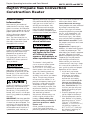
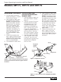
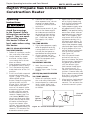
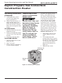
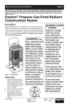
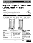
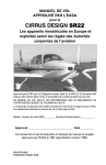
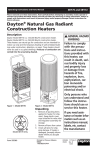
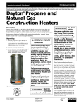
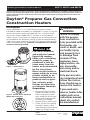
Operating Instructions and Parts Manual
6BY71, 6BY73 and 6BY74
Please read and save these instructions. Read carefully before attempting to assemble, install, operate or
maintain the product described. Protect yourself and others by observing all safety information. Failure to
comply with instructions could result in personal injury and/or property damage! Retain instructions for
future reference.
Dayton® Propane Gas Convection
Construction Heaters
Description
General hazard
warning
Failure to comply
with the precautions and instructions provided with
this heater, can
result in death, serious bodily injury
Fire, burn, inhalation
and property loss
and explosion hazard.
or damage from
Keep solid combustibles, such as building
hazards of fire,
materials, paper or
explosion, burn,
cardboard, a safe disasphyxiation, cartance away from the
heater as recommended bon monoxide
poisoning and/or
by the instructions.
Never use the heater in electrical shock.
Dayton Model 6BY71 is a 25,000 Btu/Hr construction heater
intended for indoor or outdoor use. Model 6BY73 heater is a 80,000
Btu/Hr construction heater and model 6BY74 is a 200,000 Btu/Hr
construction heater. Models 6BY73 and 6BY74 are intended for
indoor use only. These heaters use propane gas for combustion and
are intended for the temporary heating of well-ventilated buildings
under construction, alteration, or repair. This heater should never be
used in occupied dwellings. Products of combustion are vented
into the area being heated.
Figure 1 - Model 6BY71
200,
000
BTU/
HR
spaces which do or may
contain volatile or airborne combustibles or
products such as gasoline, solvents, paint
thinner, dust particles
or unknown chemicals.
Unpacking
1. Remove all packing items
applied to heater for shipFigure 2 - Models 6BY73 and 6BY74
ment. Keep plastic cover
(Model 6BY74 Shown)
caps (attached to inlet connector and hose/regulator
assembly) for storage.
2. Remove all items from carton.
3. Check all items for shipping
damage. If heater is damaged, promptly inform dealer
where you bought heater.
Form 5S5382
Printed in China
09663
0106/010/VCPVP
Only persons who
can understand and
follow the instructions should use or
service this heater.
If you need assistance or heater information such as an
instructions manual,
labels, etc. contact
the manufacturer.
DES002 117162-01
05/05
Rev. B
02/06
Dayton Operating Instructions and Parts Manual
6BY71, 6BY73 and 6BY74
Dayton Propane Gas Convection
Construction Heater
®
General Safety
Information
Make certain you read and
understand all warnings. Keep
these instructions for reference.
They are your guide to safe and
proper operation of this heater.
Safety information appears
throughout these instructions. Pay close attention to
them. Below are definitions for
the safety information listed
throughout this manual.
Under this heading, installation,
operating and maintenance
procedures or practices will
be found that, if not carefully followed, WILL result in
IMMEDIATE serious personal
injury or death.
Under this heading, installation,
operating, and maintenance
procedures or practices will be
found that, if not carefully followed, COULD result in severe
personal injury or death.
Under this heading, installation,
operating, and maintenance
procedures or practices will be
found that, if not carefully followed, MAY result in minor personal injury, product or property
damage.
IMPORTANT: Not every possible
circumstance that might involve
a hazard can be anticipated. The
warnings in this manual and on
tags or decals affixed to the unit
are therefore not all-inclusive. If
a procedure, work method, or
operating technique not specifically recommended by Dayton is
used, you must make sure it is
safe for you and others. You
should also ensure that equipment will not be damaged or
made unsafe by the operating or
maintenance method you choose.
Not for home or recreational vehicle use.
This product contains
and/or generates chemicals known to the State
of California to cause
cancer or birth defects, or
other reproductive harm.
The heater is designed for
use as a construction heater
in accordance with ANSI
Z83.7/CGA 2.14. Other standards govern the use of fuel
gases and heating products
for specific uses. Your local
authority can advise you about
these. The primary purpose
of construction heaters is to
provide temporary heating of
buildings under construction,
alteration or repair. Properly
used, the heater provides safe
economical heating. Products
of combustion are vented into
the area being heated.
We cannot foresee every use
which may be made of our
heaters. Check with your
local fire safety authority if
you have questions about
heater use.
Other standards govern the
use of fuel gases and heat
producing products for specific
uses. Your local authorities can
advise you about these.
Carbon Monoxide Poisoning:
Some people are more affected
by carbon monoxide than
others. Early signs of carbon
monoxide poisoning resemble
the flu, with headaches, dizziness and/or nausea. If you
have these signs, the heater
may not be working properly.
Get fresh air at once! Check
for proper ventilation and have
heater serviced.
Propane Gas: Propane gas is
odorless. An odor-making agent
is added to propane gas. The
odor helps you detect a propane
gas leak. However, the odor
added to propane gas may fade.
Propane gas may be present
even though no odor exists.
Make certain you read and
understand all warnings. Keep
this manual for reference. It is
your guide to safe and proper
operation of this heater.
1.Install and use heater
with care. Follow all local
ordinances and codes.
In the absence of local
ordinances and codes,
refer to the Standard for
Storage and Handling
of Liquefied Petroleum
Gas, ANSI/NFPA 58. This
instructs on the safe storage and handling of propane gases.
2.Use only propane gas set
up for vapor withdrawal.
3.Provide adequate ventilation. Before using heater,
provide at least a 108 in.2
(700 cm2) (25,000 btu
heaters), 2.5 ft2 (0.232 m2)
(80,000 btu heaters) or
6 ft2 (0.557 m2) (200,000
btu heaters) opening of
fresh, outside air.
Dayton Operating Instructions and Parts Manual
Models 6BY71, 6BY73 and 6BY74
General Safety
Information (Continued)
4.25,000 Btu/Hr Models: For
indoor and outdoor use.
80-200,000 Btu/Hr Models:
For indoor use only. Do not
use heater outdoors.
5.Keep heater away from
strong drafts, wind, water
spray, rain or dripping
water.
6.Do not use heater in occupied dwellings, sleeping
quarters, campers, tents,
or any type of unvented or
enclosed area.
7.Do not use heater in a
basement or below ground
level. Propane gas is heavier than air. If a leak occurs,
propane gas may sink to
the lowest possible level.
8.Keep appliance area clear
and free from combustible
materials, gasoline, paint
thinner and other flammable vapors and liquids. Dust
is combustible. Do not use
heater in areas with high
dust content.
9.Minimum heater clearances
from combustibles:
25,000 and 80,000 Btu heaters
Sides: 3 ft (91 cm); Top: 6
ft (1.83 m)
200,000 Btu heaters
Sides: 3 ft (91 cm); Top: 7
ft (2.1 m)
10.Keep heater at least 6 ft
(1.83 m) from propane
tank(s).
11.Keep propane tank(s)
below 100° F (37.8° C).
12.Before each use, check
heater for leaks. Never use
an open flame to check for
a leak. Apply a mixture of
liquid soap and water to
all joints. Bubbles forming
show a leak. Correct all
leaks at once.
13.Use only the hose and factory preset regulator provided with the heater.
14.Check heater for damage
before each use. Do not
use a damaged heater.
15.Check hose before each
use of heater. If highly
worn or cut, replace with
hose specified by manufacturer before using heater.
16.Do not alter heater. Keep
heater in its original state.
17.Do not use heater if
altered.
18.Locate heater on stable
and level surface if heater
is hot or operating.
19.Not intended for use on
finished floors.
20.Never block any air inlet
or air outlet openings of
heater.
21.Do not use heater as a
cooking device. Do not
place objects on top of
heater.
22.Do not leave heater unattended.
23.Never operate heater while
sleeping or unattended.
24.Keep children and animals
away from heater.
25.Always run heater with
control knob at LO, MED
or HI settings. Never set
control knob between OFF,
LO, MED or HI settings.
Flashback may occur.
26.Never move, handle or
service a hot or operating heater. Severe burns
may result. You must wait
15 minutes after turning
heater off.
27.To prevent injury, wear
gloves when handling
heater.
28.Never attach duct work to
heater.
29.Turn off propane supply to
heater when not in use.
30.Use only original replacement parts. This heater must
use design-specific parts. Do
not substitute or use generic
parts. Improper replacement
parts could cause serious or
fatal injuries.
31.Always remove heater from
propane tank after each
use. Always store propane
tank outdoors in a well
ventilated space out of the
reach of children. Never
store propane tank in a
building, garage, or any
other enclosed area. Never
store propane tank near
high heat, open flame,
or where temperatures
exceed 100° F (38° C).
32.Keep all connections and
fittings clean. Make sure
propane tank valve outlet
is clean. Check the rubber
“O” ring on the heater inlet
fuel connector for damage
before each use. Replace if
worn or damaged.
Dayton Operating Instructions and Parts Manual
6BY71, 6BY73 and 6BY74
Dayton Propane Gas Convection
Construction Heater
®
Product Identification
Ventilation
Top
Shell
Piezo
Ignitor
Button
Base
Hose/Regulator/
Fuel Gas
Connector
Assembly
Automatic
Control
Valve
Gas Inlet Connector Button
Figure 3 - 25,000 Btu/Hr Model (6BY71)
Outer
Shell
Provide at least a 3 ft2
(0.28 m2) opening of
fresh, outside air for
each 100,000 Btu/Hr of
rating while running
heater. If proper fresh,
outside air ventilation
is not provided, carbon monoxide poisoning can occur. Provide
proper fresh, outside
air ventilation before
running heater.
Theory of Operation
The Fuel System: The hose/regu-
lator assembly attaches to the
propane gas supply. This provides fuel to the heater.
The Ignition System: The piezo
ignitor lights the pilot.
The Automatic Control System:
This system causes the heater to
shut down if the flame goes out.
Propane Supply
Ignitor
Button
200,0
00 B
TU/H
R
Valve Inlet
Ball Valve Control
Knob Button
Safety Pilot Valve
Figure 4 - 80,000 (6BY73) and 200,000 (6BY74) Btu/Hr Models
[200,000 Btu/Hr shown (6BY74)]
Propane gas and propane tank(s)
are to be furnished by the user.
Use this heater only with a
propane vapor withdrawal supply system. See Chapter 5 of
the Standard for Storage and
Handling of Liquefied Petroleum
Gas, ANSI/NFPA 58. Your local
library or fire department will
have this booklet.
The amount of propane gas ready
for use from propane tanks varies.
Two factors decide this amount.
1. The amount of propane
gas in tank(s)
2. The temperature of tank(s)
Dayton Operating Instructions and Parts Manual
Models 6BY71, 6BY73 and 6BY74
Propane Supply
(Continued)
25/80,000 Btu/Hr Models: This
heater is designed to operate
with a minimum 20 lb. (9 kg)
tank. You may need two or
more tanks or one larger tank
in colder weather. Use a 100 lb.
(45 kg) tank for longer operation
or in very cold weather. Less gas
is vaporized at lower temperatures. Your local propane gas
dealer will help you select the
proper supply system.
200,000 Btu/Hr Models: This heater
will operate on a minimum 40 lb
(18 kg) propane tank but only for
a very short time if control knob is
in the lowest setting during mildly
cool weather. At higher heat settings or during colder weather
you may need two or more tanks
or one larger tank. Use a 100 lb.
(45 kg) tank for longer operation
or in very cold weather.
Less gas is vaporized at lower
temperatures. Your local propane gas dealer will help you
select the proper supply system.
The chart that follows shows
the minimum number of 100 lb
(45 kg) tanks needed to run the
heater. Connect tanks together
with a manifold.
Smaller tanks can be used
for limited run times but it is
recommended to use larger
tanks for optimum performance.
verage TemperatureNo. of 100lb
A
At Tank Location
(45 kg) tanks
25,000 Btu/Hr (6BY71)
above 0° F (-17.8° C)
below 0° F (-17.8° C)
1
1
80,000 Btu/Hr (6BY73)
above 20° F (-6.7° C)
below 20° F (-6.7° C)
1
2
200,000 (6BY74)
above 20° F (-6.7° C)
below 20° F (-6.7° C)
2
3
Specifications
Model 6BY71
• Rating: 15,000 - 25,000 Btu/Hr (15,826 - 26,376 Kj/Hr)
• Fuel: Propane/LP Gas Only
• Gas Supply Pressure to regulator:
Max. - Tank Pressure, Min. - 20 psig (137.9 kPa)
• Regulator Outlet Pressure:
High - 15 psi (103.4 kPa), Low - 5 psi (34.4 kPa)
• Ignition: Piezo Ignitor
• Minimum Ambient Temp. Rating: 0° F (-17.8° C)
• Fuel Consumption:
Pounds (kg)/Hr - Min 0.7 (0.32), Max 1.16 (0.53)
Model 6BY73
• Rating: 40,000 - 80,000 Btu/hr (42,202 - 84,404 Kj/Hr)
• Fuel: Propane/LP Gas Only
• Gas Supply Pressure to regulator:
Max. - Tank Pressure, Min. - 10 psig (68.9 kPa)
• Gas Supply Pressure regulator out: 25" W.C. (63.5 cm)
• Ignition: Piezo Ignitor
• Minimum Ambient Temp. Rating: 0° F (-17.8° C)
• Fuel Consumption: 1.9 - 3.7 lb/hr (0.86 – 1.68 kg/hr)
• Fuel Orifice Port No.: 1
• Fuel Orifice Port Size: 0.086" (2.18 mm)
Model 6BY74
• Rating: 75,000 - 200,000 Btu/hr (79,129 - 211,101 Kj/Hr)
• Fuel: Propane/LP Gas Only
• Gas Supply Pressure to regulator:
Max. - Tank Pressure, Min. - 15 psig (103 kPa)
• Gas Supply Pressure regulator out: 10 psig (68.9 kPa)
• Ignition: Piezo Ignitor
• Minimum Ambient Temp. Rating: 0° F (-17.8° C)
• Fuel Consumption: 3.5 - 9.3 lb/hr (1.6 - 4.2 kg/hr)
• Fuel Orifice Port No.: 6
• Fuel Orifice Port Size: 0.0320" (0.813 mm)
6BY71, 6BY73 and 6BY74
Dayton Operating Instructions and Parts Manual
Dayton Propane Gas Convection
Construction Heater
®
Installation
Review and understand the warnings
in the General Safety
Information section,
page 2. They are needed to safely operate
this heater. Follow all
local codes when using
this heater.
Test all gas piping and
connections for leaks
after installation or
servicing. Never use an
open flame to check
for a leak. Apply a
mixture of liquid soap
and water to all joints.
Bubbles forming show
a leak. Correct all leaks
at once.
outer shell
IMPORTANT: When the heater
is first removed from carton, the
outer shell is in the down position. Protect hands before lifting
outer shell. Never grasp bare
metal without hand protection.
1. Care must be taken to protect hands during this step.
Lift outer shell straight up
as shown in Figure 5, until
all three clips engage slots
in lower shell. Screw holes
will line up at this point.
2. Lock clips into place with 3
screws as shown in Figure
5. The heater must not be
operated unless the outer
shell is properly extended
and fully locked into place.
3 Screws
per Clip
Clip in
Slot of
Lower
Shell
(6BY73) 80,000 and
(6BY74) 200,000 Btu/Hr
Models Only
200,
000
Test all gas piping and
connections for leaks
after installation or
servicing. Never use an
open flame to check for
a leak. Apply a mixture
of liquid soap and water
to all joints. Bubbles
forming show a leak.
Correct all leaks at once.
(6BY71) 25,000 BTU/Hr
Models only
1. Provide propane supply system (See Propane Supply,
page 4).
2. Wrench tighten the fuel connector nut into the propane
tank valve (See Figure 6).
Turn fuel connector nut
counterclockwise to tighten. Threads are left-handed.
Propane
Supply Valve
Hose
Outer
Shell
BTU/
HR
Never ignite and/or
run this heater unless
the shells are fully
extended and locked
into position.
Connecting to Gas
Supply
Propane
Tank
Regulator
POL Fitting
Figure 6 - Connecting Heater to
Propane Tank
200,
000
BTU/
HR
Figure 5 - Lifting Outer Shell
(6BY74, 200,000 Btu/hr Shown)
Dayton Operating Instructions and Parts Manual
Models 6BY71, 6BY73 and 6BY74
Installation (Continued)
3. Connect hose to inlet connector (See Figure 7). Tighten
firmly using a wrench.
4. Open propane supply valve
on propane tank(s) slowly.
Note: If not opened slowly,
excess-flow check valve on
propane tank may stop gas
flow. If this happens, you
may hear a click inside the
regulator assembly, this is
the check valve closing. To
reset the excess-flow check
valve, close propane supply valve and open it again
slowly.
5. Check all connections for
leaks. Apply mixture of liquid
soap and water to gas joints.
Bubbles forming show a leak
that must be corrected.
6. Close propane supply valve.
(6BY73) 80,000 and
(6BY74) 200,000 Btu/Hr
Models Only
1. Provide propane supply system (See Propane Supply,
page 4).
2. Connect fuel gas fitting on
hose/regulator assembly
to propane tank(s). Turn
fuel gas fitting counterclockwise into threads on
tank. Tighten firmly using
a wrench. IMPORTANT:
Tighten regulator with vent
pointing down. Pointing
vent down protects regulator from weather damage.
3. Connect hose to the valve
inlet. Tighten firmly using
a wrench. You must use
the regulator supplied with
heater even if propane
tank has one.
Piezo
Ignitor
4. Open propane supply valve
on propane tank(s) slowly.
Note: If not opened slowly, excess-flow check valve
on propane tank may stop
gas flow. If this happens,
you may hear a click inside
the regulator assembly, this
is the check valve closing.
To reset the excess flow
check valve, close propane
supply valve and open
again slowly.
5. Check all connections for
leaks. Apply mixture of
liquid soap and water to
gas joints. Bubbles forming
show a leak that must be
corrected.
Hose
Propane
Supply
Valve
Propane
Tank
Hose
Regulator
POL Fitting
Inlet
Connector
Automatic Control
Valve Button
Figure 7 - Hose and Inlet Connector, Automatic
Control Valve Button and Piezo Ignitor Button
Locations
Figure 8 - Regulator Position
Hose
Valve Inlet
Figure 9 - Hose and Valve Inlet (200,000 Btu Model
Shown)
Dayton Operating Instructions and Parts Manual
6BY71, 6BY73 and 6BY74
Dayton Propane Gas Convection
Construction Heater
®
Operating
Instructions
Review and understand the warnings
in the General Safety
Information section on
page 2. They are needed to safely operate
this heater. Follow all
local codes when using
this heater.
(6BY71) 25,000 Btu heater
To Start Heater
1. Follow all installation, ventilation, and safety information.
2. Locate heater on stable
and level surface. Make
sure strong drafts do not
blow on heater.
3. Open propane supply valve
on propane tank(s) slowly.
4. Turn the heater regulator
knob clockwise to the “HI”
position.
5. Push in and hold automatic
control valve button (See
Figure 7, page 7). Push and
release piezo ignitor
button. Keep pushing piezo
ignitor button until the
burner lights. Hold control
knob down for a maximum of 10 seconds while
attempting ignition. If heater does not light, release
control knob and wait 30
seconds. Repeat step 5 to
start heater. Note: Keep
hands and face away from
outlet (around top of shell)
of heater while attempting to start heater. After
ignition, hold control knob
down for approximately 30
seconds. This activates the
automatic control system.
6. If burner will not light
after repeated tries, do not
attempt to repair heater.
Contact a qualified service
technician.
7. When burner remains lit, you
can turn the heater regulator knob counter clockwise
to the desired heat setting.
If burner goes out, turn off
gas. Check fuel supply. If
fuel supply is OK, restart
heater.
To Stop Heater
1. Tightly close propane supply
valve on propane tanks by
turning clockwise. Wait 15
minutes for the heater to
cool before handling heater.
2. Always remove the gas
supply hose from the heater and the propane tank
after each use.
To Restart Heater
1. Wait five minutes after
stopping heater.
2. Repeat steps under To Start
Heater.
(6BY73) 80,000 Btu heater
To Start Heater
1. Follow all installation, ventilation and safety information.
2. Locate heater on stable and
level surface. Make sure
strong drafts do not blow
on heater.
3. Make sure unit is turned
off by slightly depressing
and turning control knob
fully clockwise to OFF.
4. Open propane supply valve
on propane tank(s) slowly.
Note: If not opened slowly,
excess-flow check valve on
propane tank may stop gas
flow. If this happens, you
may hear a click inside the
regulator assembly, this is
the check valve closing. To
reset the excess flow check
valve, close propane supply
valve and open again slowly.
5. Slightly depress and turn
control knob counterclockwise to the LO position
(See Figure 10).
6. With the control knob
pushed all the way in,
press and release the piezo
ignitor button. Keep pressing piezo ignitor button
until the burner lights.
Hold control knob down
for a maximum of 15
seconds while attempting
ignition. If heater does not
ignite, release control knob
and wait 3 minutes before
attempting reignition.
7. After ignition, hold control
knob down for about 30
seconds. This activates the
automatic control system.
OFF
Control
Knob
LO
Piezo
Ignitor
Button
MED
HI
Figure 10 - Control Knob and Piezo Ignitor
Dayton Operating Instructions and Parts Manual
Models 6BY71, 6BY73 and 6BY74
Operating Instructions
(Continued)
8. When burner remains lit,
set heater at the desired
heat level by slightly
depressing the control
knob and turning it counterclockwise to the MED or
HI settings (See Figure 10,
page 8).
9. If burner goes out, turn
off gas. Slightly depress
and turn control knob fully
clockwise to OFF. Check
fuel supply. If adequate
fuel is available, restart
heater beginning at step 1.
Always run heater
with control knob at
LO, MED or HI settings.
Never set control knob
between OFF, LO, MED
or HI settings as flashback may occur.
Slight
Yellow
Coloring
on
Flame
Ends
Flame Patterns
Figure 11 shows a correct flame
pattern. The burner flame is
mostly blue with a slight yellow
coloring on the ends.
Figure 12 shows an incorrect
flame pattern. The flame is
mostly yellow. The incorrect
flame pattern results from low
gas pressure or from flashback.
Running heater
between settings may
cause flashback. During
flashback, the burner
flame is mostly yellow.
The flame will burn
inside the burner tube,
causing a roaring noise.
If flashback occurs, turn
heater off. After burner
tube cools, restart the
heater.
Yellow
Flame
Burner
Tube
To Stop Heater
1. Tightly close propane supply
valve on propane tank(s).
Allow heater to burn
remaining fuel in hose.
2. Shut off burner. Do this
by pushing in the control
knob and turning clockwise to the OFF position.
To Restart Heater
1. Wait five minutes after
stopping heater.
2. Restart heater by following
To Start Heater, page 8.
(6BY74) 200,000 BTU/HR
HEATER
To Start Heater
1. Before lighting pilot fully
close the ball valve (turn
knob fully clockwise).
2. Fully open the valve on the
propane cylinder and wait
15 seconds before proceeding to step 3.
3. Depress red button on
safety pilot valve admitting gas to the heater.
Then push and release the
ignitor button until the
pilot lights.
4. When the pilot lights, continue to hold the button
depressed for 30 seconds,
then release.
Ignitor
Button
Blue Flame
Blue Flame
Figure 11 - Correct Flame Pattern
at High Position
Flame Inside Burner Tube
(makes roaring noise)
Figure 12 - Incorrect Flame
Pattern During Flashback
Ball Valve
Control Knob
Button
Safety Pilot
Valve
Figure 13 - Starting Heater
[200,000 Btu/Hr Model (6BY74)]
6BY71, 6BY73 and 6BY74
Dayton Operating Instructions and Parts Manual
Dayton Propane Gas Convection
Construction Heater
®
Operating Instructions Inspecting Burner
(Continued)
5. If pilot goes out, wait 5
minutes and repeat the
lighting procedure.
6. When the pilot remains lit,
open the ball valve (turn
knob counterclockwise) to
light main burner. Partially
close valve to regulate heat
output.
TO STOP HEATER
1. Securely close valve on the
propane cylinder.
2. Continue to operate heater
until all fuel in the hose has
burned.
3. Fully close the ball valve.
TO RESTART HEATER
(6BY71) 25,000 Btu/Hr
Models only
Heater shell, top, and
heated air from heater
is very hot during
operation. Gradually
move in closer to
heater to observe
flame color. Do not
touch heater shell or
top. Do not get too
close to heated air
from heater. Severe
burns could occur.
1. Securely close valve at propane cylinder.
2. Wait 5 minutes.
3. Restart heater by following
To Start Heater, page 9.
To check for correct burner
flame, stand above but to
the side of heater and look
through the ventilation holes
in the top of the heater to
see the burner flame. Keep
a safe distance from heater
to prevent burns. The burner
flame should be mostly blue
with slight yellow coloring on
the ends. If the burner flame is
mostly yellow, the primary air
openings on the burner tube
under the heater base may be
blocked (See Figure 14).
1. Stop heater (See To Stop
Heater, page 8) and let
cool.
2. Turn heater over and
remove heat shield. Locate
the primary air openings on
the burner tube (See Figure
14). Remove any debris
blocking the primary air
openings.
3. Replace heat shield.
Primary Air
Openings
Burner
Tube
Figure 14 - Bottom View of Heater
10
Dayton Operating Instructions and Parts Manual
Models 6BY71, 6BY73 and 6BY74
Storage
Disconnect heater
from propane supply
tank(s).
For 80/200,000 Btu/Hr
models, be careful
not to locate fingers
in groves on side of
heater, in vent holes
or on bottom of shell
when collapsing shell
to the down position. Severe cuts may
occur. Always wear
hand protection when
grasping bare metal.
1. The heater should be
inspected before each use
and at least annually by a
qualified person.
2. Before each use, check
the soft "O" ring seat at
the bullnose of the POL
fitting. If the "O" ring is
cut, scuffed or otherwise
damaged, replace the POL
fitting with part number
LPA4020.
3. Turn off the gas at the
propane/LP gas supply
cylinder(s) when the heater
is not in use.
4. Do not store heater while
attached to propane tank.
Remove the gas supply
hose from the propane
tank by turning the fuel
gas connector nut clockwise.
5. Heater is to be stored
indoors in a safe manner.
The connection between
propane/LP gas supply
cylinder(s) and heater must
be disconnected, cylinder(s)
removed from the heater
and stored outdoors in
accordance with Chapter 5
of the Standard for Storage
and Handling of Liquefied
Petroleum Gases ANSI/
NFPA 58. Follow all local
codes.
6. Always store propane tanks
outdoors. Never store propane tank in an enclosed
area.
7. Place plastic cover caps
over brass fittings on inlet
connector and hose/regulator assembly.
8. Store in a dry, clean and
safe place.
11
Cleaning
Never attempt to service heater while it is
connected to propane
supply, operating or
hot. Severe burns can
occur.
1. Keep heater clean.
2. Inspect heater before each
use. Check connections for
leaks. Apply mixture of liquid soap and water to connections. Bubbles forming
show a leak that must be
corrected. Correct all leaks
at once.
3. Inspect hose/regulator
assembly before each use.
If hose is highly worn or
cut, replace.
4. Have heater inspected
yearly by a qualified service
person.
Dayton Operating Instructions and Parts Manual
6BY71, 6BY73 and 6BY74
For RepairPropane
Parts, call 1-800-323-0620
Dayton
Gas Convection
24 hours a day - 365 days a year
parts correspondence to:
Please provide following information:
Construction
HeaterAddress
Grainger Parts
- Model number
®
- Serial number (if any)
- Part description and number as shown in parts list
P.O. Box 3074
1657 Shermer Road
Northbrook, IL 60065-3074 U.S.A.
1
4
5
6
9
8
3
2
7
Figure 15 - Repair Parts Illustration, Model 6BY71
12
Dayton Operating Instructions and Parts Manual
Model
Models 6BY71
6BY71, 6BY73 and 6BY74
Repair Parts List
Ref.
No.
Description
Part Number
Qty.
1
101880-01
Shell Assembly
1
2
101864-01
Burner Assembly Kit
1
3
102445-01
Piezo Ignitor w/ Nut
1
4
103933-01
Thermocouple Bracket
1
5
101878-01
Electrode Ignitor
1
6
099236-01
Thermocouple Kit
1
7
LPA 3025
Hose & Regulator Assembly
1
8
**
Heat Shield
1
9
**
Base
1
/\
111348-14
Operation/Warning Tag
1
/\
112398-03
Rating Label
1
(**) Not a field replaceable part.
(/\) Not Shown.
13
6BY71, 6BY73 and 6BY74
Dayton Operating Instructions and Parts Manual
For RepairPropane
Parts, call 1-800-323-0620
Dayton
Gas Convection
24 hours a day - 365 days a year
Please provide following information:
Construction
Heater
- Model number
®
- Serial number (if any)
- Part description and number as shown in parts list
Address parts correspondence to:
Grainger Parts
P.O. Box 3074
1657 Shermer Road
Northbrook, IL 60065-3074 U.S.A.
1
2
6
7
8
9
23
5
11
10
12
3
16
13
14
17
15
18
19
20
22
4
21
Figure 16 - Repair Parts Illustration, Model 6BY73
14
Dayton Operating Instructions and Parts Manual
Models 6BY73
6BY71, 6BY73 and 6BY74
Model
Repair Parts List
Ref.
No. Description Part Number
Qty.
1 113785-01 Cap
2 113781-01 Upper Shell
3 113825-01 Lower Shell
4 113778-01 Ring Shield
5
**
Base
6 116617-01 Ignitor Electrode
7 103854-02 Thermocouple Bracket
8 113790-01 Thermocouple
9 100898-01 Thin Hex Nut
10 102445-01 Piezo Ignitor Kit
11 098508-01 Valve Retainer Nut
12 099393-03 Control Knob
13 117166-01 Nozzle Locator
14 116556-01 Nozzle
15 116570-01 Fuel Tube Kit
16 103929-01 Burner Tube Kit
17 099460-01 Brass Hex Cap
18 116554-01 Automatic Valve
19 117059-01 Adapter, 1/4 FPT x 1/4 MPT
20 113795-01 Female Elbow Fitting, 1/4 FPT x 3/8 FLR
21 115626-01 Hose/Regulator Assembly, 10 foot
22 117060-01 Tube Fitting
23 099230-02 Shoulder Screw
/\ 113808-07 Hang Tag
/\ 113805-04 Installation Decal
/\ 113802-20 Model Decal
/\ 116558-02 Control Position Decal
(**) Not a field replaceable part.
(/\) Not Shown.
15
1
1
1
1
1
1
1
1
2
1
1
1
1
1
1
1
1
1
1
1
1
1
1
1
1
1
1
6BY71, 6BY73 and 6BY74
Dayton Operating Instructions and Parts Manual
For RepairPropane
Parts, call 1-800-323-0620
Dayton
Gas Convection
24 hours a day - 365 days a year
Please provide following information:
Construction
Heater
- Model number
®
- Serial number (if any)
- Part description and number as shown in parts list
Address parts correspondence to:
Grainger Parts
P.O. Box 3074
1657 Shermer Road
Northbrook, IL 60065-3074 U.S.A.
12
10
9
1
25
8
17
27
24
29
13
23
7
5
6
23
15
16
20
14
22
19
18
3
11
21
4
2
26
Figure 17 - Repair Parts Illustration, Model 6BY74
16
Dayton Operating Instructions and Parts Manual
Models 6BY74
6BY71, 6BY73 and 6BY74
Model
Repair Parts List
Ref.
No. Description Part Number
Qty.
1 113814-01 Pilot Assembly
2 113835-01 Hose/Regulator Assembly, 10 foot
3 113777-01 Burner Ring Assembly
4 113778-01 Ring Shield
5 113779-01 Fuel Tube Assembly
6 113780-01 Pilot Tube Assembly
7 114178-01 Upper Shell
8 113782-01 Orifice Adapter
9 113783-01 Bracket, Pilot Mounting
10 113816-01 Orifice, LP
11
**
Base
12 113875-01 Cap
13 100898-01 Thermocouple Nut
14 113787-01 Control Valve
15 113788-01 Female Elbow Fitting, 1/4 FLR x 1/8 FPT
16 113817-01 Female Elbow Fitting, 1/4 FLR x 1/4 FPT
17 113790-01 Thermocouple
18 113821-01 Lower Shell
19 113812-01 Fitting, 1/4 FPT x 1/4 MPT
20 113793-01 Ball Valve
21 102445-01 Piezo Ignitor
22 113794-01 Valve Nut, 1/2-28
23 113795-01 Female Elbow Fitting, 1/4 FPT x 3/8 FLR
24 113796-01 Retaining Ring
25 113797-01 Ignitor Electrode
26 113798-01 Heat Shield
27 113820-01 Pilot Orifice
28 113800-01 Washer, Flat
29 113801-01 Elbow Fitting, 1/8 FPT x 1/4 CPSN
113809-01 Ball Valve Knob
113810-01 Ball Valve Knob Insert
/\ 113808-01 Hang Tag
/\ 113805-01 Installation Decal
/\ 113802-21 Model Decal
(**) Not a field replaceable part.
(/\) Not Shown.
17
1
1
1
1
1
1
1
1
1
1
1
1
2
1
1
1
1
1
1
1
1
1
2
1
1
1
1
1
1
1
1
1
1
1
Dayton Operating Instructions and Parts Manual
6BY71, 6BY73 and 6BY74
Dayton Propane Gas Convection
Construction Heater
®
Troubleshooting Chart
Never attempt to service heater while it is connected to
propane supply, operating or hot. Severe burns can occur.
Symptom
Possible Cause
Corrective Action
Burner fails to light
1.Propane supply valve closed
on propane tank(s)
2.Excess flow check valve
closed
1.Open propane supply valve
slowly
2.Close propane supply valve
on propane tank and reopen
slowly
3.Replace burner orifice
4.Replace burner/valve assembly
3.Blockage in burner orifice
4.Blockage in burner/valve
assembly
5.Piezo ignition system not
sparking
6.Pilot orifice clogged
(200,000 Btu models only)
25/80,000 Btu/Hr Models:
1.Not enough warm up time
Burner lights but goes out
when automatic control valve
button is released
2.Low gas pressure
200,000 Btu/Hr Models:
Pilot lights but goes out when
automatic control valve button
is released
Burn rate is low
3.Thermocouple loose or
needs to be replaced
4.Automatic control valve
needs to be replaced
1.Control valve is on LOW
(80/200,000 Btu models
only)
2.Plugged gas orifice
3.Low gas pressure
4.Low fuel supply
18
5.Check to assure ignitor
electrode gap is 0.120" (5
mm) for 25,000 Btu heaters
and 0.195" (3.04 mm) for
80/200,000 Btu heaters.
Check wire lead for damage.
Replace piezo ignitor and/or
ignitor electrode as necessary
6.Clean or replace pilot assembly
1.Relight, hold automatic control
valve button in 45 seconds
2.Check propane tank(s) for
proper gas supply
3.Tighten connection or
replace thermocouple
4.Replace automatic control
valve
1.Turn valve counter clockwise
to HIGH
2.Replace burner assembly for
25,000 Btu models. Replace
gas orifice for 80/200,000
Btu models
3.Check gas supply; check
regulator output
4.Consult propane gas supplier
Dayton Operating Instructions and Parts Manual
Notes
Models 6BY71, 6BY73 and 6BY74
___________________________________________________________________
___________________________________________________________________
___________________________________________________________________
___________________________________________________________________
___________________________________________________________________
___________________________________________________________________
___________________________________________________________________
___________________________________________________________________
___________________________________________________________________
___________________________________________________________________
___________________________________________________________________
___________________________________________________________________
___________________________________________________________________
___________________________________________________________________
___________________________________________________________________
___________________________________________________________________
___________________________________________________________________
___________________________________________________________________
___________________________________________________________________
___________________________________________________________________
___________________________________________________________________
___________________________________________________________________
___________________________________________________________________
___________________________________________________________________
___________________________________________________________________
___________________________________________________________________
___________________________________________________________________
___________________________________________________________________
___________________________________________________________________
___________________________________________________________________
___________________________________________________________________
___________________________________________________________________
___________________________________________________________________
19
Dayton Operating Instructions and Parts Manual
6BY71, 6BY73 and 6BY74
Dayton Propane Gas Convection
Construction Heater
®
LIMITED WARRANTY
Dayton One-Year Limited Warranty. Dayton Propane Gas Convection Construction Heater, Models covered in this manual, are warranted by Dayton Electric Mfg. Co. (Dayton) to the original user against defects
in workmanship or materials under normal use for one year after date of purchase. Any part which is determined to be defective in material or workmanship and returned to an authorized service location, as Dayton
designates, shipping costs prepaid, will be, as the exclusive remedy, repaired or replaced at Dayton’s option.
For limited warranty claim procedures, see PROMPT DISPOSITION below. This limited warranty gives purchasers specific legal rights which vary from jurisdiction to jurisdiction.
Limitation of Liability. To the extent allowable under applicable law, Dayton’s liability for consequential
and incidental damages is expressly disclaimed. Dayton’s liability in all events is limited to, and shall not
exceed, the purchase price paid.
Warranty Disclaimer. Dayton has made a diligent effort to provide product information and illustrate
the product in this literature accurately; however, such information and illustrations are for the sole purpose
of identification, and do not express or imply a warranty that the products are merchantable, or fit for a
particular purpose, or that the products will necessarily conform to the illustrations or descriptions.
Except as provided below, no warranty or affirmation of fact, expressed or implied, other than as stated in
“LIMITED WARRANTY” above is made or authorized by Dayton.
Product Suitability. Many jurisdictions have codes and regulations governing sales, construction, installation, and/or use of products for certain purposes, which may vary from those in neighboring areas. While
Dayton attempts to assure that its products comply with such codes, it cannot guarantee compliance, and
cannot be responsible for how the product is installed or used. Before purchase and use of a product, review
the product applications, and all applicable national and local codes and regulations, and be sure that the
product, installation, and use will comply with them.
Certain aspects of disclaimers are not applicable to consumer products; e.g., (a) some jurisdictions do not
allow the exclusion or limitation of incidental or consequential damages, so the above limitation or exclusion may not apply to you; (b) also, some jurisdictions do not allow limitations on how long an implied
warranty lasts, consequently the above limitation may not apply to you; and (c) by law, during the period of
this Limited Warranty, any implied warranties of implied merchantability or fitness for a particular purpose
applicable to consumer products purchased by consumers, may not be excluded or otherwise disclaimed.
Prompt Disposition. Dayton will make a good faith effort for prompt correction or other adjustment with
respect to any product which proves to be defective within limited warranty. For any product believed to
be defective within limited warranty, first write or call dealer from whom product was purchased. Dealer
will give additional directions. If unable to resolve satisfactorily, write to Dayton at address below, giving
dealer’s name, address, date and number of dealer’s invoice, and describing the nature of the defect. Title
and risk of loss pass to buyer on delivery to common carrier. If product was damaged in transit to you, file
claim with carrier.
Manufactured for Dayton Electric Mfg. Co., 5959 W. Howard St., Niles, Illinois 60714 U.S.A.
117162 01
NOT A UPC
Manufactured for Dayton Electric Mfg. Co.
Niles, Illinois 60714 U.S.A.
20