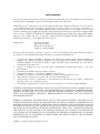
1
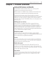
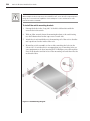
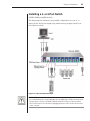
OutLook ES Series
Installer/User Guide
For models: 140ES 180ES 280ES 1160ES 2160ES 4160ES
INSTRUCTIONS
The exclamation point within an equilateral triangle is intended to alert the
user to the presence of important operating and maintenance (servicing)
instructions in the literature accompanying the appliance.
DANGEROUS VOLTAGE
The lightning flash with arrowhead symbol, within an equilateral triangle, is
intended to alert the user to the presence of uninsulated “dangerous voltage”
within the product’s enclosure that may be of sufficient magnitude to constitute
a risk of electric shock to persons.
POWER ON
This symbol indicates the principal on/off switch is in the on position.
POWER OFF
This symbol indicates the principal on/off switch is in the off position.
PROTECTIVE GROUNDING TERMINAL
A terminal which must be connected to earth ground prior to making any other
connections to the equipment.
OutLook ES Series
Installer/User Guide
Avocent, the Avocent logo and “The Power of Being There” are
trademarks of Avocent Corporation. OSCAR is a registered trademark of Apex Inc. All other marks are trademarks or registered
trademarks of their respective owners.
© 2001 Avocent Corporation. All rights reserved.
USA Notification
Warning: Changes or modifications to this unit not expressly approved by the party
responsible for compliance could void the user's authority to operate the equipment.
Note: This equipment has been tested and found to comply with the limits for a Class
A digital device, pursuant to Part 15 of the FCC Rules. These limits are designed
to provide reasonable protection against harmful interference when the equipment is
operated in a commercial environment. This equipment generates, uses and can radiate
radio frequency energy and, if not installed and used in accordance with the instruction
manual, may cause harmful interference to radio communications. Operation of this
equipment in a residential area is likely to cause harmful interference in which case the
user will be required to correct the interference at his own expense.
Canadian Notification
This digital apparatus does not exceed the Class A limits for radio noise emissions
from digital apparatus set out in the Radio Interference Regulations of the Canadian
Department of Communications.
Le présent appareil numérique n’émet pas de bruits radioélectriques dépassant les
limites applicables aux appareils numériques de la classe A prescrites dans le Règlement
sur le brouillage radioélectrique édicté par le Ministère des Communications du Canada.
Japanese Notification
Agency Approvals
UL 1950, CSA C22. 2 No. 950, EN60950, IEC 60950
FCC part 15A, EN55022, EN55024
Table of Contents
Chapter 1: Product Overview
OutLook ES Features and Benefits . . . . . . . . . . . . . . . . . 3
Safety Precautions . . . . . . . . . . . . . . . . . . . . . . . . . . . . . . 5
Chapter 2: Installation
Getting Started . . . . . . . . . . . . . . . . . . . . . . . . . . . . . . . . . 9
Rack Mounting your OutLook ES Unit . . . . . . . . . . . . . 9
Installing a 4- or 8-Port Switch . . . . . . . . . . . . . . . . . . 11
Installing a 16-Port Switch . . . . . . . . . . . . . . . . . . . . . . 13
Installing a Multiple Switch System . . . . . . . . . . . . . . . 15
Powering up the OutLook Switch System . . . . . . . . . . 18
Chapter 3: Basic Operations
Viewing and Selecting Ports and Servers . . . . . . . . . . . 21
OSCAR Navigation Basics . . . . . . . . . . . . . . . . . . . . . . 23
Setting up OSCAR . . . . . . . . . . . . . . . . . . . . . . . . . . . . . 24
Using Snapshot . . . . . . . . . . . . . . . . . . . . . . . . . . . . . . . 34
Resetting your Keyboard and Mouse . . . . . . . . . . . . . . 34
Displaying Version Information . . . . . . . . . . . . . . . . . . 35
Sending the Print Screen Keystroke . . . . . . . . . . . . . . . 35
Chapter 4: Advanced Operations
Assigning Device Types . . . . . . . . . . . . . . . . . . . . . . . . . 39
Accessing OSCAR at a Secondary Switch . . . . . . . . . . 40
Scan Behavior with a Multiuser Cascaded System . . . 40
Broadcasting to Cascaded Configurations . . . . . . . . . 42
Appendices
Appendix A: FLASH Upgrades . . . . . . . . . . . . . . . . . . . 47
Appendix B: Technical Specifications . . . . . . . . . . . . . 48
Appendix C: Technical Support . . . . . . . . . . . . . . . . . . 49
Appendix D: Connecting the 280ES DC Switch . . . . . 50
Appendix E: Troubleshooting . . . . . . . . . . . . . . . . . . . . 51
1
Product Overview
Contents
OutLook ES Features and Benefits . . . . . . . . . . . . . . . . . 3
Safety Precautions . . . . . . . . . . . . . . . . . . . . . . . . . . . . . . 5
Chapter 1: Product Overview
3
Chapter 1: Product Overview
OutLook ES Features and Benefits
Avocent’s family of OutLook switches allows you to control up to 256
computers from one keyboard, monitor and mouse.
OutLook switches are available in single or multiuser versions and are easily
customized to fit your particular network and operating system needs.
The OutLook switch system consists of the user station (your monitor,
keyboard and mouse), the switch unit and the attached servers. You can attach
additional, or secondary, switches to a primary switch (called cascading) to
expand the OutLook system. This flexibility allows you to add capacity as your
data center grows.
OSCAR graphic user interface
OutLook switches are equipped with OSCAR, our patented On-Screen
Configuration and Activity Reporting interface. OSCAR features intuitive
menus to configure your switch system and select computers. Computers can
be identified by unique name or port number, allowing you to select server
names that make sense to you. Point and click navigation with OSCAR allows
for easy configuration and computer switching.
Multiplatform support
The OutLook ES series supports PS/2 and expands to support multiple
platforms with adaptors for Apple, Sun, Unix, IBM RS/6000, HP 9000 and serial
devices. Switch easily across platforms with OSCAR.
Security
Protect your system with a screen saver password. After a user-defined time,
the screen saver mode will engage. Access is prohibited until the appropriate
password is entered to reactivate the system.
Quality video support
The OutLook system supports analog VGA, SVGA and XGA video. The
resolution you can achieve depends upon the length of cable separating your
switch and servers. Achieve resolutions of up to 1600 x 1200 with a 7 foot cable
and up to 800 x 600 with a 50 foot cable.
Plug and play
The OutLook system supports Display Data Channel Plug and Play, which
automates configuration of the monitor and is compliant with the VESA
DDC2B standard.
4
OutLook ES Series Installer/User Guide
FLASH upgradable
The OutLook ES is FLASH upgradable. This allows you to update your
firmware at any time through a simple serial connection to ensure that your
OutLook system is always running the most current version available.
Built-in scanning capabilities
A built-in scanning feature allows you to automatically monitor, or scan,
connected computers without intervention. When keyboard activity is
detected, scanning is suspended until all activity stops. Scanning then resumes
with the next server in sequence.
Cascading expansion
Each Outlook ES switch supports up to 16 directly attached servers, depending
on the model. If more than 16 are needed, multiple units can be cascaded
together with one unit designated as the primary switch and additional units
connected to it as secondary switches. This extra cascade of units allows you to
attach up to 256 servers in one system.
Figure 1.1: Example OutLook Configuration
Chapter 1: Product Overview
5
Figure 1.2: OutLook ES Model Comparison
Safety Precautions
To avoid potential video and/or keyboard problems when using Avocent products:
•
If the building has 3-phase AC power, ensure that the computer and monitor
are on the same phase. For best results, they should be on the same circuit.
•
Use only Avocent-supplied cable to connect computers and KVM switches.
Avocent warranties do not apply to damage resulting from user-supplied cable.
To avoid potentially fatal shock hazard and possible damage to equipment,
please observe the following precautions:
•
Do not use a 2-wire extension cord in any Avocent product configuration.
•
Test AC outlets at the computer and monitor for proper polarity and grounding.
•
Use only with grounded outlets at both the computer and monitor. When
using a backup power supply (UPS), power the computer, the monitor and
the OutLook unit off the supply.
NOTE: The AC inlet is the main disconnect.
6
OutLook ES Series Installer/User Guide
Rack mount safety considerations
•
Elevated Ambient Temperature: If installed in a closed rack assembly, the
operation temperature of the rack environment may be greater than room
ambient. Use care not to exceed the rated maximum ambient temperature
of the unit.
•
Reduced Air Flow: Installation of the equipment in a rack should be such
that the amount of airflow required for safe operation of the equipment is
not compromised.
•
Mechanical Loading: Mounting of the equipment in the rack should be such
that a hazardous condition is not achieved due to uneven mechanical loading.
•
Circuit Overloading: Consideration should be given to the connection of
the equipment to the supply circuit and the effect that overloading of
circuits might have on overcurrent protection and supply wiring. Consider
equipment nameplate ratings for maximum current.
•
Reliable Earthing: Reliable earthing of rack mounted equipment should
be maintained. Pay particular attention to supply connections other
than direct connections to the branch circuit (for example, use of
power strips).
2
Installation
Contents
Getting Started . . . . . . . . . . . . . . . . . . . . . . . . . . . . . . . . . 9
Rack Mounting your OutLook ES Unit . . . . . . . . . . . . . 9
Installing a 4- or 8-Port Switch . . . . . . . . . . . . . . . . . . 11
Installing a 16-Port Switch . . . . . . . . . . . . . . . . . . . . . . 13
Installing a Multiple Switch System . . . . . . . . . . . . . . . 15
Powering up the OutLook Switch System . . . . . . . . . . 18
Chapter 2: Installation
9
Chapter 2: Installation
Getting Started
Before installing your OutLook system, refer to the lists below to ensure that
you have all the items that shipped with the OutLook as well as all other items
necessary for proper installation.
Supplied with the OutLook
Your OutLook switch package contains the following items:
•
OutLook ES unit
•
Local country power cord
•
OutLook ES Installer/User Guide
•
OutLook Quick Install
•
Download Instructions
Optional items
•
19 inch Switch Mounting Bracket Kit (available from Avocent)
•
Serial cable, DB9 female, to update firmware
•
Adaptors (available from Avocent)
•
To connect a PC computer that has a serial mouse—ELC-11KM
•
To connect a Macintosh computer with an ADB keyboard—ELC-12KM
•
To connect a Sun workstation—ELC-11ST
•
To connect a serial device—ELC-15TE
•
To connect a Sync-on-green video card (option for HP9000/RS6000
computers)—ELC-11RVA, ELC-11RVB
Rack Mounting your OutLook ES Unit
You can either place your switch on your desktop or rack mount your unit into
an EIA standard rack.
Obtain a 19 inch Switch Mounting Bracket Kit (1U) to rack mount your
OutLook. Before installing the switch and other components in the rack,
stabilize the rack in a permanent location. Start rack mounting your
equipment at the bottom of the rack, then work to the top. Avoid uneven
loading or overloading of racks.
CAUTION Rack Loading: Overloading or uneven loading of racks may result in shelf or rack
failure, causing damage to equipment and possible personal injury. Stabilize racks in a
permanent location before loading begins. Mount components beginning at the bottom of the
rack, then work to the top. Do not exceed your rack load rating.
10
OutLook ES Series Installer/User Guide
CAUTION Power Considerations: Connect only to the power source specified on the unit.
When multiple electrical components are installed in a rack, assure the total component power
ratings do not exceed circuit capabilities. Overloaded power sources and extension cords
present fire and shock hazards.
To install the switch mounting bracket:
1.
Line up the holes in the “long side” of the kit’s side brackets with the
screw holes in the switch.
2.
With an Allen wrench, fasten the mounting brackets to the switch using
two #8-32 button head socket cap screws on each side.
3.
Attach the six rack nut/holders to the mounting rail of the rack so that the
nut is positioned on the inside of the rack.
4.
Mount the switch assembly to the rack by matching the holes in the
“short side” of each bracket to an appropriate set of matching holes on
your equipment rack, then inserting #10-32 Phillips screws through the
slots in the bracket and the holes in the mounting rail and then into the
rack/nut holders.
Figure 2.1: Rack Mounting Diagram
Chapter 2: Installation
11
Installing a 4- or 8-Port Switch
(140ES, 180ES and 280ES models)
The diagram below illustrates one possible configuration for your 4- or
8-port switch. Follow the step-by-step instructions to properly install your
new OutLook switch.
Figure 2.2: 8-Port Installation Example
WARNING: To reduce the risk of electric shock or damage to your equipment:
- Do not disable the power cord grounding plug. The grounding plug is an important safety feature.
- Plug the power cord into a grounded (earthed) outlet that is easily accessible at all times.
- Disconnect the power from the unit by unplugging the power cord from either the electrical
outlet or the unit.
12
OutLook ES Series Installer/User Guide
To install a 4- or 8-port switch:
1.
Prepare the location for the switch. See Rack Mounting your OutLook ES
Unit in this chapter if you are rack mounting the unit.
2.
Select cables with appropriate connectors and length. (See Appendix B for
cable specifications.)
NOTE: Cable length affects video quality as well as keyboard and mouse data timing. The
maximum cable length is determined in part by the computer and peripherals used. Not all
systems will give satisfactory results at the maximum length.
3.
Connect the mouse, video and keyboard cables to the appropriate switch
connectors. Note that all keyboard and mouse cables are 6-pin miniDIN
PS/2 style and all the video cables are 15-pin VGA/SVGA style. (These
connectors are located on the left rear of the switch unit, with additional
connectors on the front of the OutLook 280 unit.)
NOTE: Keyboard and mouse connectors on the OutLook switch work with cables that have a
locking mechanism. The cable lock prevents cables from becoming disconnected from the switch
connectors due to the weight of the cable bundles or accidental tension from handling cables.
4.
Select the computer that is to be connected to Port 1. Attach the computer’s
mouse to the appropriate connector on Port 1. Attach the computer’s monitor
to the 15-pin VGA connector. Attach the computer’s keyboard to the
appropriate connector. Bundle and label the cables for easy identification.
5.
Repeat step 4 for all remaining computers to be connected to the switch unit.
6.
Connect the power cord to the switch unit.
Chapter 2: Installation
13
Installing a 16-Port Switch
(1160ES, 2160ES and 4160ES models)
The diagram below illustrates one possible configuration for your 16-port
switch. Follow the step-by-step instructions to properly install your new
OutLook switch.
Figure 2.3: 16-Port Installation Example
WARNING: To reduce the risk of electric shock or damage to your equipment:
- Do not disable the power cord grounding plug. The grounding plug is an important safety feature.
- Plug the power cord into a grounded (earthed) outlet that is easily accessible at all times.
- Disconnect the power from the unit by unplugging the power cord from either the electrical
outlet or the unit.
14
OutLook ES Series Installer/User Guide
To install a 16-port switch:
1.
Prepare the location for the switch. See Rack Mounting your OutLook ES
Unit in this chapter if you are rack mounting the unit.
2.
Select cables with appropriate connectors and length. (See Appendix B for
specifications.) All 16-port switches require one high density 50-pin for
every two computer cable sets of keyboard, video and mouse connectors.
3.
Connect the high-density cable to the appropriate port on the back of the
switch. You will note that each 50-pin connector is labeled with two
numbers and symbols. The symbols help you determine the switch port
number of the two keyboard, video and mouse cable sets.
NOTE: Cable length affects video quality as well as keyboard and mouse data timing. The
maximum cable length is determined in part by the computer and peripherals used. Not all
systems will give satisfactory results at the maximum length.
4.
Select the two computers to be connected to the first port. Connect each
computer’s monitor to the 15-pin VGA connector. Connect each
computer’s keyboard and mouse to the appropriate connector. Bundle and
label the cables for easy identification.
5.
Repeat steps 3 and 4 for all remaining computers to be connected to the
switch unit.
6.
Connect the power cord to the switch unit.
Chapter 2: Installation
15
Installing a Multiple Switch System
The following diagram illustrates one possible cascading configuration using
your OutLook switch. Perform this installation if you want to add another
switch to your existing system. Follow the step-by-step instructions to properly
cascade your new OutLook switch.
Figure 2.4: Multiple Switch Installation Example
16
OutLook ES Series Installer/User Guide
Checklist of Steps for Adding a Secondary Switch
At the Primary Switch
3.
6.
At the Secondary Switch
1.
Select its location.
2.
Connect cables to station connections.
4.
Plug in power cord.
5.
Power up switch.
7.
Connect servers.
8.
Power up servers.
9.
If switch was previously used as a primary
device, then reset OSCAR defaults (optional).
Connect cables to a port.
Assign specific device types.
10. Check status of secondary servers.
11. Check mouse, keyboard and video functions.
12. Perform Snapshot.
13. Perform Snapshot.
14. Turn off Delay Time.
To add a secondary switch to an OutLook switch system:
1.
Place the secondary switch in the desired location. Make sure the switch
is turned off and unplugged.
2.
Connect the video, mouse and keyboard interconnecting cables to the user
port connections on the secondary switch.
3.
Connect the video, mouse and keyboard cables (in this order) to the user
port connections on the primary switch.
4.
Plug the power cord into its socket on the secondary switch.
5.
Power up the secondary switch.
6.
At the primary switch, open OSCAR to assign a specific device type. This
designation makes the primary switch aware of the secondary switch:
a.
b.
c.
d.
Press Print Screen to open the OSCAR Main dialog box.
Click Setup - Devices - Device Modify.
Click the port number that identifies the number of ports of the
secondary switch: 4-port, 8-port, 10-port or 16-port.
Click OK.
7.
Leave the power turned on to the secondary switch and connect the video,
mouse and keyboard cables (in this order) from the servers to the switch port.
8.
Power up the servers attached to the secondary switch.
Chapter 2: Installation
9.
17
If a secondary switch was previously used as a primary switch, reset
OSCAR settings by doing the following:
a.
b.
c.
d.
e.
f.
At the primary switch, press Print Screen to open the Main dialog
box. Select the port number of the secondary switch.
Press Print Screen again to gain access to the Main dialog box on the
secondary switch.
Click Setup - Devices. Click Defaults, then click OK.
From the Setup dialog box, click Names. Click Defaults, then click OK.
From the Setup dialog box click Flag. Deselect Displayed, click OK.
Press Escape to exit OSCAR at the secondary switch.
10. At the primary switch, check the status symbols of the servers in the Main
dialog box. If symbols are different from what is expected, see the Status
Symbols section in Appendix E.
11. At the primary switch, check mouse and keyboard functions and video
signals for each computer.
12. Perform the Snapshot procedure at the primary switch to save mouse and
keyboard settings:
a.
b.
c.
Press Print Screen to open the Main dialog box.
Click Commands, then click Snapshot.
Repeat steps a and b for additional primary switches.
13. Perform the Snapshot procedure at the secondary switch to save keyboard
and mouse settings:
a.
b.
c.
d.
e.
Press Print Screen to open the Main dialog box then select the port
number of the secondary switch.
Press Print Screen again to gain access to OSCAR at the secondary switch.
Click Commands, then click Snapshot.
Press Escape to exit OSCAR from the secondary switch.
Repeat steps a - d for additional secondary switches.
14. Turn off Delay Time at the secondary switch (this prevents OSCAR from
displaying at the secondary switch when selecting servers):
a.
b.
c.
d.
e.
Press Print Screen to open the Main dialog box, then select the port
number of the secondary switch.
Press Print Screen again to gain access to OSCAR at the secondary switch.
Click Setup - Menu.
Type Ø for Delay Time, then click OK.
Repeat steps a - d for additional secondary switches.
15. If all of the primary switches in the system show the correct port and
server configuration and your mouse, keyboard and video function
properly, your OutLook switch system is ready for operation.
NOTE: When connecting the video, mouse and keyboard cables from your servers to a running
OutLook system, always connect the keyboard cable last. The switch detects the system power
of the secondary switch or server through the keyboard cable. When the keyboard cable is
connected last, the switch initializes both the keyboard and mouse interfaces to the system,
allowing you to add a new switch without restarting your system.
18
OutLook ES Series Installer/User Guide
Powering up the OutLook Switch System
The switch must be powered up before the attached servers since the switch
stores mouse and keyboard connection and rate data for each server. The
switch uses this information to initialize the keyboard and mouse interfaces of
the servers. If the servers are turned on before the switch, the servers may
exhibit abnormal or erratic behavior.
To power up the OutLook switch system:
1.
Turn on the monitors.
2.
Turn on the primary switch.
3.
Turn on the servers attached to the primary switch.
4.
Turn on the secondary switch (if applicable).
5.
Turn on the servers attached to the secondary switch (if applicable).
Checking the OutLook switch system startup behavior
During system startup, check to see that your primary OutLook switch does
the following:
•
Lights the blue LED power indicator on the front of the switch (if applicable)
•
Identifies the mouse and keyboard and sets their default states
•
Displays copyright information about the OutLook switch and firmware
•
Selects a port and displays its number in the status flag on the monitor
See the following table for the default port number that displays in the status
flag on startup for each of the OutLook switch models.
Default Port Number Displayed in Status Flag
OutLook Model
User
Displays Port
140ES, 180ES, 1160ES
A
1
280ES, 2160ES
A
1
B
2
A
1
B
2
C
3
D
4
4160ES
If the copyright information and status flag do not appear, check that the
monitor is connected and powered up.
3
Basic Operations
Contents
Viewing and Selecting Ports and Servers . . . . . . . . . . . 21
OSCAR Navigation Basics . . . . . . . . . . . . . . . . . . . . . . 23
Setting up OSCAR . . . . . . . . . . . . . . . . . . . . . . . . . . . . . 24
Using Snapshot . . . . . . . . . . . . . . . . . . . . . . . . . . . . . . . 34
Resetting your Keyboard and Mouse . . . . . . . . . . . . . . 34
Displaying Version Information . . . . . . . . . . . . . . . . . . 35
Sending the Print Screen Keystroke . . . . . . . . . . . . . . . 35
Chapter 3: Basic Operations
21
Chapter 3: Basic Operations
Viewing and Selecting Ports and Servers
Use the Main dialog box to select, control and configure servers in your
OutLook system.
To access the Main dialog box:
Press Print Screen to start OSCAR and gain access to the Main dialog box.
Figure 3.1: Main Dialog Box
Viewing the Status of your Switch System
The status of servers and switches in your system is indicated in the far right
column of the Main dialog box. The following table describes the status symbols.
OSCAR Status Symbols
Symbol
Description
Server connected and powered up.
Connected server is powered down or is not operating properly.
Secondary switch connected and powered up.
Secondary switch is powered down or is not operating properly.
On a multiuser switch, this letter corresponds to the lettered user port to
which you are connected.
On a multiuser switch, this letter identifies the user currently connected to
the server.
22
OutLook ES Series Installer/User Guide
Selecting Servers
Use the Main dialog box to select servers. When you select a server, the OutLook
switch reconfigures the keyboard and mouse to the settings for the selected server.
To select servers:
1. Double-click the server name or port number.
- or If the display order is by port, type the port number and press Enter.
- or If the display order is by name, type the first few letters of the name of the
server to establish it as unique and press Enter.
To select the previous server:
Press Print Screen and then Backspace. This key combination toggles you
between the previous and current connection.
To disengage from a server:
Press Print Screen, then Alt+Ø. This key combination leaves you in a free state
with no server selected. The status flag on your desktop displays Free.
Soft Switching
After you press Print Screen to initially open OSCAR, you can select servers
without displaying OSCAR. This is called a soft switch.
To configure servers for selecting without displaying OSCAR:
1.
Click Setup - Menu.
2.
For Delay Time, type the number of seconds of delay desired before the
Main dialog box is displayed after Print Screen is pressed.
3.
Click OK.
To select servers without displaying OSCAR:
1.
To select another server, press Print Screen. If the display order of your server
list is by port (Port button is depressed), type the port number and press Enter.
- or If the servers are in name order (Name button is depressed), type the first
few letters of the name of the server to establish it as unique and press
Enter. If the selection is performed before the Delay Time has expired,
OSCAR does not display.
2.
To switch back to the previous server, press Print Screen then Backspace.
Chapter 3: Basic Operations
23
OSCAR Navigation Basics
Use the following keystrokes to navigate though OSCAR.
This Keystroke
Does This
Print Screen
Opens OSCAR. (To print a screen, see Sending the Print Screen
Keystroke in Chapter 3.)
F1
Opens the Help screen for the current dialog box.
Escape
Closes the current dialog box without saving changes and returns to
the previous one. In Main dialog box, it closes OSCAR and returns
to the selected server. In a message box, it closes the pop-up box
and returns to the current dialog box.
Alt+X
Closes current dialog box and returns to previous one.
Alt+O
Selects the OK button, then returns to the previous dialog box.
Enter
Completes the switch operation in Main dialog box and exits
OSCAR. In a message box, it closes the pop-up box and returns to
the current dialog box.
Single-click, Enter
In a text box, it selects the text for editing and enables the left and right
arrow keys to move the cursor. Press Enter again to quit the edit mode.
Print Screen , Alt+Ø Immediately disengages user from a server. Status Flag displays Free.
Print Screen , Pause Immediately turns on screen saver mode and prevents access to that
particular station if it is password protected.
Up/Down Arrows
Moves the cursor from line to line in lists.
Right/Left Arrows
Moves the cursor between columns. When editing a text box, these
keys move the cursor within the column.
Page Up/Down
Pages up and down through Name and Port lists.
Home/End
Moves the cursor to the top or bottom of a list.
Shift+Del
Deletes from current selection to all lines below it when editing a
scan list.
Insert
In the Scan dialog box, inserts the first server listed in the Main
dialog box. In the Name dialog box, inserts a character space.
Alt+Down Arrow
In the Scan dialog box in the Name, Port or Sec columns, moves the
cursor down through the list of servers.
Alt+Up Arrow
In the Scan dialog box in the Name, Port or Sec columns, moves the
cursor up through the list of servers.
Alt+Home
In the Scan dialog box in the Name, Port or Sec columns, moves
cursor to the first server listed in the Main dialog box.
Alt+End
In the Scan dialog box in the Name, Port or Sec columns, moves
cursor to the last server listed in the Main dialog box.
Caps Lock
Disabled. (Use the Shift key to change case.)
24
OutLook ES Series Installer/User Guide
Setting up OSCAR
You can configure your OutLook system from the Setup dialog box. Use
the Scan, Menu, Flag, Security and Broadcast options to manage routine
tasks for your servers. Use the Devices and Names options when initially
setting up your switch system to assign device types and to identify servers
by unique names.
To access the Setup dialog box:
1.
Press Print Screen. The Main dialog box appears.
2.
Click Setup in the Main dialog box. The Setup dialog box appears.
Figure 3.2: Setup Dialog Box
Setup Features
Scan
Set up a custom scan pattern.
Menu
Change the server listing between numerically by port and alphabetically by name.
Change the Delay Time before the Main dialog box displays after pressing
Print Screen.
Flag
Change display, timing, color or location of the status flag.
Security
Set passwords to restrict server access and enable the screen saver.
Broadcast
Simultaneously control multiple servers through keyboard and mouse actions.
Devices
Identify device types attached to your switch, including servers and other switches.
Names
Identify servers by unique names.
Chapter 3: Basic Operations
25
Assigning Server Names
Use the Names dialog box to identify servers by a unique name that makes
sense to you and reset names back to the default settings.
To access the Names dialog box:
1.
Press Print Screen. The Main dialog box will appear.
2.
Click Setup - Names. The Names dialog box appears.
Figure 3.3: Names Dialog Box
To assign names to servers:
1.
Double-click or press Enter to select the text in the Name box. Type a
name. Names of servers may be up to 15 characters long. Legal characters
include: A-Z, a-z, 0-9 and (space). Press Backspace or Delete to delete an
incorrect entry. Press the Arrow keys to move the cursor in the Name box.
Press Insert or the Space Bar to insert a character space.
2.
Repeat step 1 for each server in the system.
3.
Click OK to save the names.
- or Click Defaults then click OK to restore default settings.
- or Click X or press Escape to exit the dialog box without saving changes.
To list servers alphabetically by name:
Press Alt+N or click Name in the Main dialog box.
NOTE: Before you can assign names to servers attached to secondary switches, you must first
make the primary switch aware of the secondary switch. See Assigning Device Types in Chapter 4.
26
OutLook ES Series Installer/User Guide
Changing the Display Behavior
Use the Menu dialog box to change the server display order, set the Delay Time
for OSCAR after pressing Print Screen and change the switch connection mode.
To access the Menu dialog box:
1.
Press Print Screen. The Main dialog box will appear.
2.
Click Setup - Menu. The Setup dialog box appears.
Figure 3.4: Menu Dialog Box
To choose the display order of servers in the Main dialog box:
1.
Click Name to display servers alphabetically by name or click Port to
display servers numerically by port number.
2.
Click OK.
To set a Delay Time for OSCAR:
1.
Type in the number of seconds you want to delay display of OSCAR after
you press Print Screen.
2.
Click OK.
Setting a display Delay Time for OSCAR allows you to complete a soft switch
without OSCAR displaying. For more information, see Soft Switching in this chapter.
To set the switch mode:
1.
Select the type of switching mode you desire:
Cooperative (default setting) to have the OutLook maintain the current
user connection; the current user won’t be disconnected if another user
requests connection.
- or -
Chapter 3: Basic Operations
27
Preemptive to have the OutLook allow any user to select any server at any
time; a request from another user disconnects the current user.
2.
Click OK.
Setting up a Scan Pattern
In scan mode, the switch automatically scans from port to port (server to
server). Each user can scan the entire system sequentially or designate a
custom scan pattern by specifying servers and durations.
To access the Scan dialog box:
1.
Press Print Screen. The Main dialog box will appear.
2
Click Setup in the Main dialog box. The Setup dialog box appears.
3.
Click Scan in the Setup dialog box. The Scan dialog box appears.
Figure 3.5: Scan Dialog Box
To scan all servers in the system:
1.
Click Defaults in the Scan dialog box.
2.
In the Sec column, type the number of seconds (from 1 to 99) of desired
Delay Time before the scan moves to the next server in the sequence.
3.
Move the cursor to the next line or press the Down Arrow and repeat step
2 for each server.
4.
Click OK.
5.
From the Commands menu, select Scan Enabled to start the scan mode.
28
OutLook ES Series Installer/User Guide
To remove a server from the scan list:
1.
In the Scan dialog box, click the server to be removed.
2.
Press Delete.
— or—
Press Shift+Delete to remove the selected server and all entries below it.
3.
Click OK.
To set up a custom scan pattern:
1.
In the Scan dialog box, type the name or port number of the server you want
to scan.
— or—
On the first line, press Insert; the first server listed in the Main dialog box
appears. To select the server to include in your scan pattern, use the
following keyboard commands in the Name, Port or Sec column:
a
b
c
d
Press Alt+Down Arrow to move the cursor down the list of servers.
Press Alt+Up Arrow to move the cursor up the list of servers.
Press Alt+Home to move the cursor to the first server listed.
Press Alt+End to move the cursor to the last server listed.
2.
In the Sec column, type the number of seconds (from 1 to 99) of desired
Delay Time before the scan moves to the next server in the sequence.
3.
Move the cursor to the next line or press the Down Arrow and repeat steps 1
and 2 for each of the remaining servers to be included in the scan pattern.
4.
Click OK.
NOTE: If you later remove a server from the list in the Device Modify dialog box, this change
may affect a custom scan pattern.
To start the scan mode:
Select Scan Enabled in the Commands menu.
To cancel scan mode:
Clear Scan Enabled in the Commands menu if OSCAR is open.
— or—
Select a server if OSCAR is open.
— or—
Move the mouse or press any key on the keyboard if OSCAR is not open. Scan
will stop at the currently selected server.
Chapter 3: Basic Operations
29
Controlling the Status Flag
The status flag displays on your desktop and shows the name or port number
of the selected server or the status of a particular port. Use the Flag dialog box
to display the flag by port number or by server name, limit the time the flag
displays, change the flag color, make the flag transparent or opaque and
change the flag’s location on the desktop.
Status Flag Examples
Flag
Flag Description
Flag type is by name.
Flag type is by port number.
Flag shows broadcast mode is activated.
To access the Flag dialog box:
1.
Press Print Screen. The Main dialog box will appear.
2.
Click Setup - Flag. The Flag dialog box appears.
Figure 3.6: Flag Dialog Box
To determine how the status flag is displayed:
1.
Select Name to display the server by name or select Port to display by port.
2.
Select Displayed to show the flag all the time or select Timed to display
the flag for only 5 seconds after switching.
3.
Select a flag color in Display Color.
4.
In Display Mode, select Opaque for a solid color flag or select Transparent
to see the desktop through the flag.
30
OutLook ES Series Installer/User Guide
5.
To position the status flag on the desktop:
a.
Click Set Position to gain access to the Position Flag screen.
Figure 3.7: Position Flag
b.
c.
Left click on the title bar and drag to the desired location.
Right click to return to the Flag dialog box.
NOTE: Changes made to the flag position are not saved until you click OK in the Flag dialog box.
6.
Click OK to save settings or click X to exit without saving changes.
Setting User Console Security
Use the Security dialog box to set security on your user station. You can
establish a screen saver mode that engages after your station remains inactive
for a user-specified time. Once engaged, your station will remain locked until
you press any key or move the mouse. You will then need to type in your
password to log back in to the system.
To access the Security dialog box:
1.
Press Print Screen. The Main dialog box will appear.
2.
Click Setup - Security. The Security dialog box appears.
Figure 3.8: Security Dialog Box
To set or change the password:
1.
Single-click and press Enter or double-click in the New text box.
2.
Type the new password in the New text box and press Enter.
Chapter 3: Basic Operations
31
Passwords can be up to 12 characters long and are case sensitive. Legal
characters are: A-Z, a-z, 0-9 and (space).
3.
In the Repeat box, type the password again and press Enter.
4.
Click OK.
To password protect your user station:
1.
Set your password as described in the previous procedure.
2.
Select Enable Screen Saver.
3.
Type the number of minutes for Delay Time (from 1 to 99) to delay
activation of password protection and the screen saver feature.
4.
For Mode, select Energy if your monitor is EnergyStar compliant;
otherwise select Screen.
CAUTION: Monitor damage can result from the use of Energy Mode with monitors not
compliant with EnergyStar.
5.
(Optional) Click Test to activate the screen saver test that lasts 10 seconds
then returns you to the Security dialog box.
6.
Click OK.
To log in to your user station:
1.
Press any key on the keyboard or move your mouse. The Password dialog
box appears. Type your password and then click OK.
2.
Press Print Screen to start OSCAR.
To remove password protection from your user station:
1.
From the Main dialog box, click Setup - Security. The Password dialog box
appears. Type your password and then click OK.
2.
In the Security dialog box, single-click and press Enter or double-click in
the New box. Leave the box blank. Press Enter.
3.
Single-click and press Enter or double-click in the Repeat box. Leave the
box blank. Press Enter.
4.
Click OK.
32
OutLook ES Series Installer/User Guide
To enable the screen saver mode with no password protection:
1.
If your station is password protected, perform the previous procedure first.
2.
Now select Enable Screen Saver.
3.
Type the number of minutes for Delay Time (from 1 to 99) that you want
to delay activation of the screen saver.
4.
Choose Energy if your monitor is EnergyStar compliant; otherwise you
should select Screen.
CAUTION: Monitor damage can result from the use of Energy Mode with monitors not
compliant with EnergyStar.
5.
(Optional) Click Test to activate the screen saver test, which lasts 10
seconds, then returns you to the Security dialog box.
6.
Click OK.
NOTE: Activation of the screen saver mode disconnects the user from a server. The status flag
displays Free.
To exit the screen saver mode:
Press any key or move your mouse. The Main dialog box appears.
To turn off the screen saver:
1.
In the Security dialog box, clear Enable Screen Saver.
2.
Click OK.
To immediately turn on the screen saver:
Press Print Screen, then press Pause. This command only works when you
are connected to a server.
Broadcasting to Servers
Use Broadcast to simultaneously control more than one server in a system.
This feature is useful when you want to ensure that all selected servers receive
identical input. For each server receiving the broadcast, you can choose to
broadcast keystrokes and/or mouse movements independently. In a cascaded
system, you can broadcast to any combination of servers in the entire system.
To access the Broadcast dialog box:
1.
Press Print Screen. The Main dialog box will appear.
2.
Click Setup - Broadcast. The Broadcast dialog box appears.
Chapter 3: Basic Operations
33
Figure 3.9: Broadcast Dialog Box
NOTE: Broadcasting Keystrokes - The keyboard state must be identical for all servers
receiving a broadcast to interpret keystrokes identically. Specifically, the Caps Lock and
Num Lock modes must be the same on all keyboards. While the switch attempts to send
keystrokes to the selected servers simultaneously, some servers may inhibit and thereby delay
the transmission.
NOTE: Broadcasting Mouse Movements - For the mouse to work accurately, all systems
must have identical mouse drivers, desktops (such as identically placed icons) and video
resolutions. In addition, the mouse must be in exactly the same place on all screens. Because
these conditions are extremely difficult to achieve, broadcasting mouse movements to multiple
systems may have unpredictable results.
To broadcast to selected servers:
1.
Select the mouse and keyboard checkboxes for the servers that are
to receive the broadcast commands.
— or—
Press the Up Arrow or Down Arrow keys to move the cursor to the server
that is to receive the broadcast command. Then press Alt+K to select the
keyboard checkbox and/or Alt+M to select the mouse checkbox. Repeat
for additional servers.
2.
Click OK to save the settings.
3.
From the Commands menu, select the Broadcast Active checkbox to
activate broadcasting.
NOTE: If using a multiuser switch, only one user may select Broadcast Active.
4.
From the user station, type the information and/or perform the mouse
movements you want to broadcast.
34
OutLook ES Series Installer/User Guide
To turn broadcasting on or off:
From the Commands menu, click to enable or disable the Broadcast Active checkbox.
Using Snapshot
Snapshot saves the keyboard and mouse information of the servers that are
powered up. The OutLook switch uses this information to initialize the
keyboard and mouse interfaces of the servers. If power is turned off to the
switch before you perform the Snapshot procedure, then you must restart each
server to reestablish keyboard and mouse communication with the switch.
Perform Snapshot after you install the switch system, add servers to the system
or change the mouse or keyboard.
How Snapshot works with power outages:
If you have performed Snapshot, once power is restored after a power outage,
OutLook switches automatically restore the keyboard and mouse settings of
each server. If you use an uninterrupted power supply, connect the switches to
the same source as the rest of the system.
To save keyboard and mouse settings:
1.
Power up the servers for which you want to save settings.
2.
From the Commands menu, click Snapshot.
3.
A message box displays identifying that the keyboard and mouse settings
have been saved.
4.
Click X to close the message box.
Resetting your Keyboard and Mouse
If a keyboard or mouse locks up, you may be able to reestablish operation of
these peripherals by issuing a reset command. The reset command sends a
hot-plug sequence to the server. The hot-plug sequence to a plug and play
server causes the mouse and keyboard settings to be sent to the OutLook. With
communication reestablished, functionality is restored to you.
To reset the mouse and keyboard values:
1.
From the Commands menu, click Reset.
2.
A message box displays indicating that the mouse and keyboard have been
reset. Click X to close the message box.
NOTE: If you cannot access the Commands menu to perform the reset procedure, press the
Reset button on the back panel of the switch.
Chapter 3: Basic Operations
35
Displaying Version Information
Use the Version dialog box to display the version number of the firmware as
well as keyboard and mouse information for the currently selected server.
This information facilitates system troubleshooting and support. For optimum
performance, keep your firmware current.
To display version information:
1.
Click Version in the Commands dialog box. The Version dialog box appears.
2.
Click X to close the Version dialog box.
Sending the Print Screen Keystroke
The Print Screen key has many functions in the OSCAR environment. Refer to
the chart below to be properly access the feature you need.
Press Print Screen
This Many Times
To Do This
OutLook switch as a stand-alone switch
1
Open OSCAR.
2
Send the Print Screen keystroke to the currently selected device.
OutLook switch connected to another Avocent switch
1
Open OSCAR at the primary switch.
2
Open OSCAR at the selected secondary switch.
3
Bring both OSCAR menus up on the monitor at the same time.
4
Send the Print Screen keystroke to the currently selected device.
36
OutLook ES Series Installer/User Guide
4
Advanced Operations
Contents
Assigning Device Types . . . . . . . . . . . . . . . . . . . . . . . . . 39
Accessing OSCAR at a Secondary Switch . . . . . . . . . . 40
Scan Behavior with a
Multiuser Cascaded System . . . . . . . . . . . . . . . . . 40
Broadcasting to Cascaded Configurations . . . . . . . . . 42
Chapter 4: Advanced Operations
39
Chapter 4: Advanced Operations
Assigning Device Types
Use the Devices dialog box to assign device types to either make your primary
switch aware of a secondary switch or to delete a device from the Main dialog box.
To access the Devices dialog box:
1.
Press Print Screen. The Main dialog box will appear.
2.
Click Setup - Devices. The Devices dialog box appears.
Figure 4.1: Devices Dialog Box
After you assign a device type to a secondary switch, the port numbering changes.
In the above example, Port 2-1 is a secondary port. The 2 indicates the port number
on the primary switch and 1 is the port number on the secondary switch.
To assign a device type:
1.
In the Devices dialog box, select the port number.
2.
Click Modify. The Device Modify dialog box appears.
Figure 4.2: Device Modify Dialog Box
40
OutLook ES Series Installer/User Guide
3.
Choose one from the following:
•
•
•
No Device: If no switch or server is attached and you want to delete it
from the list of devices in the Main dialog box
Computer: If a server is attached (default setting)
Port number: If a secondary switch is attached, select the number of
ports it has.
4.
Click OK.
5.
Repeat steps 2–4 for each port you want to assign a device type.
6.
Click OK in the Devices dialog box to save settings.
— or –
Click Defaults then OK to restore settings.
Accessing OSCAR at a Secondary Switch
With cascaded configurations, you specify settings at the primary switch. All
naming, scanning, status flag attributes, OSCAR attributes, device settings and
passwords must be set at the primary switch.
You will access OSCAR at the secondary switch to set up broadcasting, add
another level of security in cascaded configurations or use Snapshot to save the
secondary mouse and keyboard settings. You’ll also access the secondary OSCAR
for firmware version information or to reset the secondary mouse and keyboard.
You should only change two settings in OSCAR on a secondary switch
because adjustments can cause conflicts between the secondary and primary
switches. Specifically, ensure that your secondary switch is set to Port Order
view and Preemptive mode. All other settings should be set to the default
factory settings.
To open OSCAR at a secondary switch:
1.
Press Print Screen to open the Main dialog box at the primary switch.
2.
Double-click the number of the cascaded port to be accessed.
— or—
Select the cascaded port and press Print Screen again to display OSCAR at
the secondary switch.
Scan Behavior with a Multiuser Cascaded System
With a multiuser switch, scan behavior is influenced by multiple users and
cascaded switches. A multiuser switch in the primary position and any
single-user switch in the secondary position creates a situation that can
change the scan pattern. The scan behavior modes are described in the
following chart with three examples to better illustrate scan behavior.
Chapter 4: Advanced Operations
41
Scan Mode
Behavior
Full Connection
User has keyboard and mouse control.
Watch Connection
User sees video only; has no keyboard or mouse control.
Skip Connection
User cannot select the server because access is unavailable. Either
the port connection is in use or the power is turned off to the port.
Scan Behavior Examples
Full Connection
Watch Connection
Example 1: User A is
accessing server 2-4. User B
wants to scan servers on the
secondary switch at Port 1 of
the primary switch.
Example 2: User A is
accessing server 2-4. User B
wants to scan server 2-4.
Example 3: User A is
accessing server 2-4. User
B wants to scan server 2-2.
Behavior: Activities of User
A can be monitored but keyboard strokes or mouse
movements by User B cannot
be passed on to server 2-4.
Behavior: Since User A
occupies the primary port
connection at Port 2, server
2-2 is unavailable to User B.
Behavior: Any keyboard stroke
or mouse click by User B will
stop the scanning and pass the
keystrokes or mouse movements
to the currently selected server.
Skip Connection
42
OutLook ES Series Installer/User Guide
Broadcasting to Cascaded Configurations
Broadcasting to a cascaded configuration requires special consideration at both
the primary and secondary switches. Follow these step-by-step instructions to
properly configure your system for cascaded broadcasting.
To set up servers attached to secondary switches:
1.
From the Main dialog box at the primary switch, click to select the port
number or server name of the secondary switch to which you want to
broadcast; press Print Screen to display OSCAR for the secondary switch.
2.
Click Setup - Broadcast.
3.
From the Broadcast dialog box, select the keyboard and mouse checkboxes
for each server that is to receive keystrokes and/or mouse movements.
Figure 4.3: Broadcast Dialog Box
4.
Click OK to save settings.
5.
From the Commands menu, click the Broadcast Active checkbox to
activate the broadcast mode for the secondary switch.
6.
Press Print Screen to open OSCAR at the primary switch.
7.
Repeat steps 1 - 5 to send broadcast commands to the servers attached to
additional secondary switches.
To set up servers attached to primary switches:
1.
From the Main dialog box at the primary switch, click Setup - Broadcast.
2.
From the Broadcast dialog box, select the keyboard and mouse checkboxes
for each server that is to receive keystrokes and/or mouse movements.
3.
Click OK to save settings.
Chapter 4: Advanced Operations
43
4.
From the Commands menu, click the Broadcast Active checkbox to
activate the broadcast mode for the primary switch.
5.
From a user station attached to the primary switch and connected to the
secondary switch, type the information and/or select the mouse
movements you want to broadcast.
NOTE: Once you exit OSCAR, broadcasting is activated and any keystrokes or mouse
movements will be active.
To turn off broadcast mode for a cascaded configuration:
1.
From the Commands menu at the primary switch, clear the Broadcast
Active checkbox.
2.
In the Main dialog box at the primary switch, click to select the port
number or name of the secondary switch to which you want to stop
broadcasting commands. Press Print Screen to display OSCAR at the
secondary switch.
3.
Click Commands.
4.
From the Commands menu, clear the Broadcast Active checkbox.
44
OutLook ES Series Installer/User Guide
Appendices
Contents
Appendix A: FLASH Upgrades . . . . . . . . . . . . . . . . . . . 47
Appendix B: Technical Specifications . . . . . . . . . . . . . 48
Appendix C: Technical Support . . . . . . . . . . . . . . . . . . 49
Appendix D: Connecting the 280ES
DC Switch . . . . . . . . . . . . . . . . . . . . . . . . . . . . . . . . 50
Appendix E: Troubleshooting . . . . . . . . . . . . . . . . . . . . 51
Appendices
47
Appendices
Appendix A: FLASH Upgrades
OutLook Firmware Upgrade Instructions
You can update the firmware of your OutLook switch by using a special update
utility provided by Avocent. This utility automatically configures the port
communications settings to allow direct downloading from the connected server.
To update your firmware, you need the following items:
•
•
•
•
Computer running Windows NT, Windows 95, Windows 98 or Windows 2000
Available serial port (COM port) on the server
Standard serial cable (DB-male) that connects the switch and the server
Firmware update
To update firmware:
1.
Connect the standard serial cable to a COM port on the server and to the
serial connector on the back panel of the switch. Make a note of which
COM port you have chosen, then turn on the switch.
2.
Go to http://www.avocent.com/support and click on Downloads to access
the firmware update file. Once the download is complete, navigate to the
drive where you have saved the firmware update and unzip the file.
3.
Double-click to run the file WUpDate.exe.
4.
In the dialog box that displays, select the desired language and COM port.
5.
Click Load.
6.
Once the firmware is updated, the following message displays: Download
complete. Click Done to exit the dialog box.
7.
The switch automatically reboots after the update is completed.
Possible error conditions
If the download does not execute properly, verify the following:
•
•
•
•
•
Verify that the COM port is correct.
Verify that no other program is currently using the COM port, or that a
previous DOS window/shell is open that had used the desired COM port.
Verify that no other copies of the WUpDate utility are currently running.
Verify that a straight through (1-to-1) type of serial cable is used, not a null
modem serial cable.
Verify in the selected COM port’s Advanced Port settings that the FIFO
buffers are selected and that the receive buffer is set to High.
WARNING: While upgrading, do not use your computer for anything else or switch between
windows. Close all other windows if necessary. If the update was unsuccessful (such as during
a power outage), repeat the procedure.
48
OutLook ES Series Installer/User Guide
Appendix B: Technical Specifications
Product Specifications
Dimensions
Model
140ES, 180ES, 280ES, 1160ES, 2160ES, 4160ES
Height
1.75 in
(4.5 cm)
Depth
8.00 in
(20.3 cm)
Width
17.00 in
(43.2 cm)
140ES
5.25 lb
(2.38 kg)
180ES
5.25 lb
(2.38 kg)
280ES
5.70 lb
(2.60 kg)
1160ES
5.70 lb
(2.60 kg)
2160ES
5.70 lb
(2.60 kg)
4160ES
5.70 lb
(2.60 kg)
Weight
Input Power Requirements
Rated Voltage
100 – 240VAC
Rated Frequency
50 – 60 Hz
Rated Input Current
1.0A Max
Temperature Range
Maximum Ambient Operating
32° – 104° F
(0° – 40° C)
Ambient Storage and Shipping - 40° – 185° F
( - 40° – 85° C)
Maximum Internal Rack
(40° C)
104° F
Relative Humidity
Operating
20% – 80%
Non-operating
5% – 90%
Video Modes Supported
VGA, SVGA, XGA
Maximum Cable Lengths
Console to switch
18 ft - If you need more than 18 feet, use LongView, Avocent’s
long-line driver.
Computer to switch
7 ft
12 ft
25 ft
50 ft
Switch to switch
25 ft
1600 x 1200 dpi
1280 x 1024 dpi
1024 x 768 dpi
800 x 600 dpi
Appendices
49
Appendix C: Technical Support
Our Technical Support staff is ready to assist you with any installation or
operating issues you encounter with your Avocent product. If an issue should
develop, follow the steps below for the fastest possible service:
1.
Check the pertinent section of the manual to see if the issue can be
resolved by following the procedures outlined.
2.
Check our web site at www.avocent.com/support to search the knowledge
base or use the on-line service request.
3.
Call Avocent Technical Support for assistance at (888) 793-8763. Visit the
Avocent web site at http://www.avocent.com/support and click on Getting
Support for current phone support hours.
50
OutLook ES Series Installer/User Guide
Appendix D: Connecting the 280ES DC Switch
Use only #18 AWG stranded wire UL 1007 or UL 1015. The maximum length
should not exceed 10 meters (32.8 feet).
WARNING: Always disconnect power before changing any wiring. To reduce the risk of
electric shock or damage to the equipment, this product must be installed in accordance with
the following guidelines.
This product is intended to be connected to a DC power source that can be classified
as a secondary circuit in accordance with applicable national requirements for
Information Technology Equipment. Generally, these requirements are based on
the International Standard for Safety for Information Technology Equipment, IEC
950. The source must have one pole (Neutral/Return) referenced to earth ground in
accordance with local/regional electric codes and/or regulations.
This product is intended to be installed only in areas that comply with ETSI-300-132-2.
This product must be connected to a power distribution device that provides a means
for disconnecting power from the branch supply circuit. The power distribution
device must be provided with an overcurrent protective device suitable for
interrupting faulty currents available from the main source and rated no more than .3
AMPS at the distribution device. The green/yellow lead of the power cable assembly
must be connected to a suitable ground/earth terminal on the power distribution unit.
Do not rely on the rack or rack chassis to provide adequate ground/earth continuity.
1. Red wire
2. Black wire
3. Green/Yellow striped wire
Use chassis ground connection only.
4. 48 Volt DC (to external fused 48
volt DC supply)
To connect the wires
1.
Plug connector (1) into receptacle. Do not use ground connection
through connector.
2.
Insert stripped wires (2) and tighten screws (3).
Appendices
51
Appendix E: Troubleshooting
VIDEO
No OSCAR or video at server
Check for loose video cable connection or bad video cable.
Confirm Devices, Names and Flag settings.
Reset settings to default in these dialog boxes.
No OSCAR at primary switch
On the front panel of the switch, confirm that the LED lights (if applicable).
Reconnect the power cord to the switch.
Replace the power cord.
Check AC outlet for power.
Check that the monitor is turned on.
Check the control for brightness on the monitor.
Replace the monitor.
MOUSE
Mouse error on start up
Check for loose mouse cable connection.
Check for PS/2 keyboard and mouse cable cross-connections.1
Replace the mouse cable.
Check the Internet for the latest firmware version of the mouse.
If a mouse is connected to the serial port on the server, install the Serial-to-PS/2
mouse adaptor (Avocent part number ELC-11KM).
Mouse displays erratic behavior or pointer is frozen on display
Reset the mouse in OSCAR:2 Main - Commands, then type Alt+R.
Reset the mouse by pressing the Reset button on the back panel of the switch.2
Check the Internet for the latest firmware version of the mouse.
1 Some servers require restarting when the keyboard cable is disconnected from the server.
For this reason, perform these tests when the server can be restarted.
2 Must have performed Snapshot in order for the reset function to work properly.
52
OutLook ES Series Installer/User Guide
KEYBOARD
Console keyboard is not working or cannot start OSCAR
Ensure that Delay Time is off. Click Setup - Menu, Type 0 secs for Delay Time.
Check keyboard operation. See if the Num Lock and Caps Lock keys light.
Keyboard worked, but then stopped working with one server
Check for loose keyboard cable connection or bad keyboard cable.1
Check maximum length of the keyboard cable (maximum length = 12 feet).
Check maximum length of station cable extension.
Press the Reset button on the back panel of the switch to reset all keyboards
and mouse devices on all servers (must have performed Snapshot).
Keyboard never worked on one server
Check for PS/2 keyboard and mouse cable cross connections.1
Replace interconnecting keyboard cable.1
Disconnect and reconnect the interconnecting keyboard cable.1
Check length of the interconnecting keyboard cable (maximum length = 12 feet).
Check maximum length of station cable extension.
Replace the station keyboard.1
Keyboard signal never worked on all servers or stopped working with one server
Check for loose station keyboard cable.
Check maximum length of station cable extension (maximum length = 12 feet).
Replace the station keyboard.1
Press the Reset button on the back panel of the switch (must have performed
Snapshot in order for reset function to work properly).
Check for loose interconnecting keyboard cables.
Keyboard error on startup
Check the Web for the latest firmware version of the keyboard.
Keystrokes shifted, swaps upper case for lower case
Server keyboard left in shifted state when last selected. Press both Shift keys to
change keystrokes to lower case or upper case.
Keystrokes are not working properly
Check that keystrokes are not in locked mode. On the left side of the keyboard,
press Caps Lock+Shift+Control+Alt.
On the right side of the keyboard, press Alt+Control+Shift.
1
Some servers require restarting when the keyboard cable is disconnected from the server.
For this reason, perform these tests when the server can be restarted.
Appendices
53
STATUS SYMBOLS
No
or
shows next to server number or name
Check for loose keyboard cable connection between server and switch.
Disconnect and reconnect the keyboard cable at the same port number on the switch.
Restart OSCAR: Press Escape or click X in Main dialog box to exit OSCAR.
Then press Print Screen.
shows next to cascaded port
Disconnect and reconnect the keyboard cable at the same port number on the switch.
Replace keyboard cable.
shows next to server number or name when
is expected
PS/2 interconnecting cable from another switch is connected in error to the port.
Disconnect the secondary switch and connect the server to the port.
shows next to primary server when
is expected
Confirm selection of the correct number of ports (4, 8, 10, 16) for the secondary
switch in the Device Modify dialog box.
Confirm that all port settings are set to Standard if not connected to a
secondary switch.
SWITCH BEHAVIORS
Switch selects servers at will
Ensure that scanning is off. To turn off scanning, click Main - Commands, then
clear Enabled.
Same keystrokes or mouse movements display on one or more servers
Ensure that broadcasting is turned off. To turn off broadcasting, click Main Commands, then clear Activated.
Can only select Port 1 on a secondary switch (selecting Port 1-4 selects Port 1-1)
Ensure correct settings in the Device Modify dialog box at the primary switch.
Confirm the selection of the correct number of ports (2, 4, 8, 10, 16) for the
secondary switch: Main - Setup - Devices - Device Modify.
Confirm that all port settings are set to Standard if connected to servers.
Broadcasting unavailable
Ensure that broadcasting is not in use by another user. Request that the other
user deactivate broadcasting.
54
OutLook ES Series Installer/User Guide
FIRMWARE UPDATES
Firmware does not download
Check for loose cable connections.
Replace serial cable.
Check that the serial cable is connected to the COM port on the server and to
the serial port on the switch.
Download timed out
Confirm that the correct port was selected.
If another program is using the same port, quit the program.
If a serial cable is not installed, install one. If it is defective, replace it.
Visit the Avocent web site to see the latest firmware updates for your OutLook
switch at: http://www.avocent.com/.
Appendices
55
LIMITED WARRANTY
Avocent Corporation warrants to the original retail purchaser that this product is and will be free from defects in
materials and workmanship for a period of 12 months from the date of purchase.
Additionally, all Avocent products carry an unconditional thirty-day satisfaction guarantee. If, for any reason,
you are dissatisfied with the performance of this product, you may return it to the point of purchase for a
refund of the purchase price (excluding shipping charges). This guarantee does not apply to special order
products, and may not be available through all resellers. During the warranty period, purchaser must promptly
call Avocent for a RETURN MATERIALS AUTHORIZATION (RMA) number. Make sure that the RMA number
appears on the packing slip, proof of purchase, AND ON THE OUTSIDE OF EACH SHIPPING CARTON.
Unauthorized returns or collect shipments will be refused.
Ship prepaid to:
Avocent Corporation
4991 Corporate Drive
Huntsville, AL 35805 U.S.A.
Telephone: (256) 430-4000
The above limited warranty is voided by occurrence of any of the following events, upon which the product is
provided as is, with all faults, and with all disclaimers of warranty identified below:
1.
2.
3.
4.
5.
6.
7.
8.
If non-Avocent approved cabling is attached to the unit. Poorly constructed and miswired cabling can
diminish video quality and damage equipment. Avocent manufactured cabling is built to high quality
standards utilizing overall braided shield to comply with FCC emission standards, and each cable is
individually tested under load.
If defect or malfunction was caused by abuse, mishandling, unauthorized repair, or use other
than intended.
If unauthorized modifications were made to product.
If unreported damages occurred in any shipment of the product.
If damages were due to or caused by equipment or software not provided by Avocent.
If the unit is used with non-grounded or incorrectly polarized AC power.
If the product is used in contradiction to any instruction provided by any User Guide or Instruction
Sheet provided to you or with the product.
If the product is damaged due to power surges, water exposure or act of God including lightning.
EXCEPT AS SPECIFICALLY PROVIDED ABOVE AND TO THE MAXIMUM EXTENT ALLOWED BY LAW,
AVOCENT CORPORATION DISCLAIMS ALL WARRANTIES AND CONDITIONS WHETHER EXPRESS,
IMPLIED, OR STATUTORY AS TO ANY MATTER WHATSOEVER INCLUDING, WITHOUT LIMITATION,
TITLE, NON-INFINGEMENT, CONDITION, MERCHANTABILITY OR FITNESS FOR ANY PARTICULAR
OR INTENDED PURPOSE.
EXCEPT AS EXPRESSLY PROVIDED ABOVE AND TO THE MAXIMUM EXTENT ALLOWED BY LAW,
AVOCENT CORPORATION SHALL NOT BE LIABLE FOR ANY SPECIAL, INDIRECT OR CONSEQUENTIAL
DAMAGES (INCLUDING WITHOUT LIMITATION, LOSS OF PROFIT, LOSS OF BUSINESS, LOSS OF
INFORMATION, FINANCIAL LOSS, PERSONAL INJURY, LOSS OF PRIVACY OR NEGLIGENCE) WHICH MAY
BE CAUSED BY OR RELATED TO, DIRECTLY OR INDIRECTLY, THE USE OF A PRODUCT OR SERVICE,
THE INABILITY TO USE A PRODUCT OR SERVICE, INADEQUACY OF A PRODUCT OR SERVICE FOR
ANY PURPOSE OR USE THEREOF OR BY ANY DEFECT OR DEFICIENCY THEREIN EVEN IF AVOCENT
CORPORATION OR AN AUTHORIZED AVOCENT DEALER HAS BEEN ADVISED OF THE POSSIBILITY
OF SUCH DAMAGES OR LOSSES.
©2001 Avocent Corporation. All rights reserved.
For Technical Support:
Email: [email protected]
www.avocent.com
Avocent Corporation
4991 Corporate Drive
Huntsville, Alabama 35805-6201 USA
Tel: +1 256 430 4000
Fax: +1 256 430 4031
Avocent International Ltd.
Avocent House, Shannon Free Zone
Shannon, County Clare, Ireland
Tel: +353 61 715 292
Fax: +353 61 471 871
Avocent Asia Pacific
Singapore Branch Office
100 Tras Street, #15-01/2
Amara Corporate Tower
Singapore 079027
Tel: +65 227 3773
Fax: +65 223 9155
Avocent Germany
Gottlieb-Daimler-Straße 2-4
D-33803 Steinhagen
Germany
Tel: +49 5204 9134 0
Fax: +49 5204 9134 99
Avocent Canada
50 Mural Street, Unit 5
Richmond Hill, Ontario
L4B 1E4 Canada
Tel: +1 877 992 9239
Fax: +1 877 524 2985
590-203-001 Rev. A