1
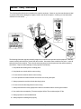
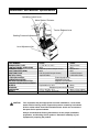
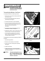
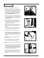
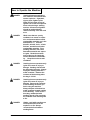
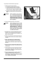
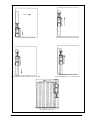
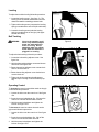
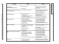
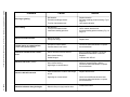
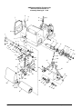
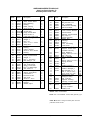
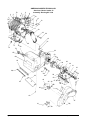
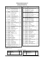
E
Operator's
Manual
Classic 12
Belt Sander
READ THIS BOOK
This book has important information for the use and safe operation of this machine. Failure to read
this book prior to operating or attempting any service or maintenance procedure to your ALTO
machine could result in injury to you or to other personnel; damage to the machine or to other property
could occur as well. You must have training in the operation of this machine before using it. If you
cannot read English, have this manual explained fully before attempting to operate this machine.
Si Ud. o sus operadores no pueden leer el Inglés, se hagan explicar este manual completamente antes
de tratar el manejo o servicio de esta máquina.
All directions given in this book are as seen from the operator’s position at the rear of the machine.
For new books write to: ALTO U.S. INC., 2100 Highway 265, Springdale, Arkansas 72764.
Form No. 70048A
11/00
AMERICAN SANDERS TECHNOLOGY
Printed in the
Contents of this Book
Section I - Operator's Manual
Operator Safety Instructions ......................................................... 3
Machine Safety Statements .......................................................... 5
Introduction and Machine Specifications ....................................... 6
Electrical Connection Instructions ................................................. 7
How to Transport the Machine ...................................................... 8
One Person .............................................................................. 8
Two People .............................................................................. 9
Machine Set-Up ......................................................................... 10
How to Operate the Machine ...................................................... 11
Sanding Cuts and Sandpaper .................................................. 14
Sander Adjustment Procedures .................................................. 15
Routine Maintenance.................................................................. 17
Troubleshooting ......................................................................... 18
Section II - Parts Manual
Assembly Drawing #1 ................................................................ 22
Assembly Parts List #1 ........................................................... 23
Assembly Drawing #2 ................................................................ 24
Assembly Parts List #2 ........................................................... 25
Assembly Drawing #3 ................................................................ 26
Assembly Parts List #3 ............................................................. 27
Wiring Diagram .......................................................................... 28
Page
2
AMERICAN SANDERS TECHNOLOGY Classic 12 Belt Sander Operator's Manual
OPERATOR SAFETY INSTRUCTIONS
WARNING
AVERTISSEMENT
ADVERTENCIA
DANGER means:
Severe bodily injury or death can occur to you or other personnel if the
DANGER statements found on this machine or in this Owner's Manual are
ignored or are not adhered to. Read and observe all DANGER statements
found in this Owner's Manual and on your machine.
WARNING means:
Injury can occur to you or to other personnel if the WARNING statements
found on your machine or in this Owner's Manual are ignored or are not
adhered to. Read and observe all WARNING statements found in this Owner's
Manual and on your machine.
CAUTION means:
Damage can occur to the machine or to other property if the CAUTION statements found on your machine or in this Owner's Manual are ignored or are not
adhered to. Read and observe all CAUTION statements found in this Owner's
Manual and on your machine.
DANGER:
Failure to read the Owner's Manual prior to operating or attempting any service or maintenance procedure to your American Sanders Technology machine could result in injury to
you or to other personnel; damage to the machine or to other property could occur as
well. You must have training in the operation of this machine before using it. If you
cannot read English, have this manual explained fully before attempting to operate
this machine.
DANGER:
Sanding/finishing wood floors can create an environment that can be explosive. The
following safety procedures must be adhered to:
•
Cigarettes, cigars, pipes, lighters, pilot lights and any other source of ignition can create
an explosion when active during a sanding session. All sources of ignition should be
extinguished or removed entirely from the work area.
•
Work areas that are poorly ventilated can create an explosive environment when certain
combustible materials are in the atmosphere, i.e., solvents, thinners, alcohol, fuels,
certain finishes, wood dust and other combustible materials. Floor sanding machines
can cause flammable material and vapors to burn. Read the manufacturer's label on all
chemicals used to determine combustibility. Keep the work area well ventilated.
•
Spontaneous combustion or an explosion can occur when working with sanding dust.
The sanding dust can ignite and cause injury or damage. Sanding dust should be
disposed of properly. Always empty the sanding dust into a metal container that is
located outside of any building.
•
Remove the contents of the dust bag when the bag is 1/3 full. Remove the contents of
the dust bag each time you finish using the machine. Never leave a dust bag unattended
with sanding dust in it.
•
Do not empty the contents of the dust bag into a fire.
•
Hitting a nail while sanding can cause sparks and create an explosion or fire. Always
countersink all nails before sanding floors.
DANGER:
Operating a machine that is not completely or fully assembled could result in injury or
property damage. Do not operate this machine until it is completely assembled. Keep
all fasteners tight. Keep adjustments according to machine specifications.
DANGER:
Electrocution could occur if the machine is used on a power circuit that repeatedly trips or is
undersized. Have a licensed electrician check the fuse, circuit breaker or power supply.
AMERICAN SANDERS TECHNOLOGY Classic 12 Belt Sander Operator's Manual
Page
3
Page
DANGER:
Electrocution could occur if maintenance and repairs are performed on a unit that is not properly
disconnected from the power source. Disconnect the power supply before attempting any
maintenance or service.
DANGER:
Electrocution could occur if machine is used on ungrounded electrical circuit. Never remove
or disable the grounding supply conductor on the electrical cord. Consult an electrician if the
grounding conductor is missing or if you suspect your circuit is not grounded properly.
DANGER:
Use of this machine with a damaged power cord could result in an electrical shock. Do not
use the machine if the power cord is damaged. Do not use the electrical cord to move the
machine.
DANGER:
Electrocution or injury could occur if the power cord is run over or damaged by the sander.
Keep the cord free from under the machine to avoid contact with the sandpaper. Always lift
the power cord over the machine.
DANGER:
Moving parts of this machine can cause serious injury and/or damage. Keep hands, feet and
loose clothing away from all moving parts of the sander.
DANGER:
Operating a sander without all guards, doors or covers in place can cause an injury or damage.
Always check to make sure that all of the guards, doors and covers are secure and in place.
DANGER:
Injury to the operator or bystanders could occur if the machine's power is on while performing
maintenance, changing or adjusting the belt, or changing the dust bag.
DANGER:
Attempting to adjust the belt tracking while the machine is on can cause injury and/or damage.
Do not perform belt tracking adjustments while the machine is running.
WARNING:
Failure to read and observe all safety statements found on your machine or in this Owner's
Manual can result in serious injury or damage. Read and observe all safety statements. Make
sure that all labels, decals, warnings, cautions, and instructions are fastened to the machine.
Get new labels from your authorized American Sanders Technology distributor.
WARNING:
Sanding dust can be airborne and can be breathed in while operating a sander. Always wear
a dust mask while operating sanding equipment.
WARNING:
Injury to the eyes and/or body can occur if protective clothing and/or equipment is not worn
while sanding.
Always wear safety goggles, protective clothing, and a dust mask while
performing any sanding operation.
WARNING:
Bodily injury could occur if power is applied to the machine with the power switch already in
the "ON" position. Always check to assure that the power switch is in the "OFF" position
before applying power to the power cable.
CAUTION:
Maintenance and repairs performed by unauthorized personnel could result in damage or
injury. Maintenance and repairs performed by unauthorized personnel will void your warranty.
Servicing of this unit must always be referred to an authorized American Sanders Technology
distributor.
CAUTION:
Use of this machine to move other objects or to climb on could result in injury or damage. Do
not use this machine as a step or furniture. Do not ride on this machine.
CAUTION:
Damage could occur to the machine if not properly kept in a dry building for storage.
the machine in a dry building.
CAUTION:
The machine is heavy. When transporting the machine, remove the motor. Get help to lift
the machine and motor.
CAUTION:
Serious damage to the floor can occur if the machine is left running in one spot while the
sanding drum is in contact with the floor. To avoid damage to the floor, feather cut in at a normal
sanding rate. Do not dwell while lowering or raising the contact wheel. Always sand at a
constant rate.
4
Store
AMERICAN SANDERS TECHNOLOGY Classic 12 Belt Sander Operator's Manual
Machine Safety Statements
The following safety decals are mounted on the machine as shown. If these or any other machine decal, label
or plate should become damaged or illegible, install a new decal in its place. Contact your local authorized
distributor for new decals.
The following information signals potentially dangerous conditions to the operator and/or equipment. Read this
manual carefully and familiarize yourself with the machine. Know when these conditions can exist. Locate all
safety devices on the machine. Then, take the necessary steps to train the personnel that will be operating
the machine. Report machine damage or faulty operation immediately.
1. Keep hands and clothing clear of rotating parts.
2. Keep hands on controls with the motor running.
3. Do not leave the machine with the motor running.
4. Do not operate the machine with the access door or the belt guard open.
5. Always operate the machine with the dust bag in place.
6. Do not remove the dust bag with the motor running.
7. Always disconnect the motor pigtail power cord from the handle before servicing the machine.
8. Use caution when transporting. The motor weighs 120 lbs. The machine weighs 157 lbs.
9. Always operate in a well ventilated area.
10. Always dispose of sanding dust properly.
AMERICAN SANDERS TECHNOLOGY Classic 12 Belt Sander Operator's Manual
Page
5
Introduction and Machine Specifications
Operating Control Lever
Motor Starter / Protector
Tension Release Lever
Sanding Pressure Adjustment
Level Adjustment Nut
PART NUMBER
ABRASIVE BELT SIZE
CONTACT WHEEL SPEED (RPM)
ABRASIVE SPEED
DUST FAN SPEED (RPM)
DUST FAN FLOW
MOTOR (07055A)
LEVELING CONTROL
OPERATING CONTROL
MOTOR STARTER/PROTECTOR
SANDING PRESSURE ADJUSTMENT
WHEELS
BEARINGS
DIMENSIONS
WEIGHT
CAUTION:
07055C
07056C
11-7/8" W x 31-1/2" L
30cm X 80cm
2850
2375
5262 sfm (surface feet per minute)
22m/second
6800
5667
234 cfm (cubic feet per minute)
110 liters/second
4hp 230V 60Hz
2.2kW 230V 50Hz
Externally adjustable
Adjustable lever/grip
Magnetic circuit breaker
Infinitely adjustable
Replaceable 3½" O.D.
89mm
Radial ball, permanently lubricated
37"H x 18½"W x 35"L
94cm x 47cm x 89cm
277 lbs. (300 lbs. with cord)
126 kg (136kg with cord)
Your equipment may be inappropriate on some installations. Some softer
woods used in flooring cannot support the pressure created by hard wheels.
A felt or rubber wheel should be used when these woods are encountered.
See parts list for optional wheels.
Always consult with the flooring manufacturer on the proper installation,
preparation, and finishing of their product. Determine suitability of your
equipment in preparing the product.
Page
6
AMERICAN SANDERS TECHNOLOGY Classic 12 Belt Sander Operator's Manual
Electrical Connection Instructions
CAUTION:
This machine will operate only on AC frequency and voltage shown on the motor
nameplate. Make sure you have the correct frequency and voltage before connecting the
power cord to an outlet. The machine has a plug as shown below.
Figure 1
Note: European machines are not equipped with an electrical plug.
This machine must be connected to an electrically ground circuit in order to protect the operator from electric shock.
This machine has an approved power cord with three conductors as well as a plug with three terminals. Connect the
plug into a three holed receptacle. For maximum protection against electric shock, use a circuit that is protected
by a ground fault circuit interrupter.
DANGER:
Electrocution could occur if the machine is exposed to water or rain. Keep the machine
in a dry building.
DANGER:
Electrocution could occur if machine is improperly connected to the electrical system. To
prevent possible electric shock, always use a 3-wire electrical system connected to an
electrical ground. For maximum protection against electrical shock, use a circuit that
is protected by a ground fault circuit interrupter. Consult your electrical contractor.
DANGER:
Electrocution could occur if the ground pin is tampered with in any way. Do not cut,
remove, or break the ground pin. Do not try to fit a three-terminal plug into a receptacle
or connector body other than a three holed receptacle or connector body matching the
machine plug. If the outlet does not fit the plug, consult your electrical contractor.
DANGER:
Electrocution could occur if the machine is used with a damaged plug or power cord. If
the cords or plugs are worn or damaged in any way, have them replaced by an authorized
service person or electrician.
Extension Cords
Use only an approved three-pronged extension cord with two main conductors and one earthing conductor. This
machine’s power cord has a wire size of 10 gauge. This machine is equipped with a 100' power cord. When greater
range is needed follow the table below to determine wire guage of additional footage. Refer to the following chart
for extension cord information.
Feet/Wire Guage (Stranded Copper)
Source Voltage
0 - 100'
100 - 250'
Use Voltage
208
6
Booster
230
10
8
If motor appears to labor or takes a considerably longer time to come up to speed, reduce sanding pressure.
AMERICAN SANDERS TECHNOLOGY Classic 12 Belt Sander Operator's Manual
Page
7
How to Transport the Machine
WARNING:
The machine is heavy. Remove
the motor from the machine before
transporting. Get help loading the
machine and motor.
Transporting the Machine - One Person
To transport the machine, follow this procedure:
1. Make sure the power cable is disconnected from
the electrical outlet.
2. Disconnect the handle pigtail cord connection.
(twist and pull) See figure 2.
3. Loosen the belt tension T-screw completely.
4. Grasp the belt guard immediately above the left
hand truck wheel and pull to gain access to the
drive belts. Remove the drive belts.
See figure 3.
Figure 2
5. Unscrew the motor mounting knob clear of the
counterbore on chassis. See figure 4.
6. Straddle the machine. With your legs, lift the motor
off of the chassis. Take the motor to worksite.
7. Lift the chassis by grasping the front and rear
handle. Bring the belt guard against your chest.
Take the chassis to worksite.
To assemble the machine after transporting, follow this
procedure:
1. Open the belt guard door.
Figure 3
2. Place the motor assembly on the chassis.
3. Screw in the motor mounting knob completely.
See figure 4.
4. Install the drive belts.
5. Tighten the belt tension T-screw only until the
contact drive wheel belt does not squeal upon start
up. Do not over tighten.
CAUTION:
Page
8
Premature bearing failure can occur if the belt tension is set too
tight. The fan drive belt should
deflect ½" at the center of the span
with 5 lbs. of pressure.
Figure 4
AMERICAN SANDERS TECHNOLOGY Classic 12 Belt Sander Operator's Manual
NOTE: It is not always necessary to adjust the fan
belt independently during this procedure or during
replacement.
NOTE: New drive belts may shed particles of rubber
until seated to the pulley grooves. This seating
process can take up to 24 hours to accomplish.
6. Close the belt guard door.
7. Plug the motor pigtail in. Twist clockwise to lock.
Transporting the Machine - Two People
When transporting the machine with two people follow
this procedure:
1. One operator places hands under the front of the
machine main casting.
2. Person #2 lifts the machine by the handle.
AMERICAN SANDERS TECHNOLOGY Classic 12 Belt Sander Operator's Manual
Page
9
Machine Set-Up
To set-up your machine follow this procedure:
1. Familiarize yourself with the machine and read all
danger, warning and caution statements. Make
sure all operators of this machine have read this
Owner's Manual. If they cannot read English,
have the manual explained fully before allowing
anyone to operate the sander.
2. Locate the power supply. The receptacle should
be compatible with the plug. The receptacle must
be grounded and must be fused (30 amp) to avoid
an electrical hazard.
Figure 5
3. Clip the dust bag to the elbow. See figure 5.
Cross the strings on the dust bag and draw tight
over the flare on the elbow. Wrap the string
around the elbow and secure.
4. Wind the power cord through the cable arm. See
figure 6. Keep the power cord out of path of
equipment.
5. Pull the draw latch forward to release the access
door to gain entry to the sanding chamber.
Figure 6
6. Rotate the release lever forward. See figure 7.
7. Install a new abrasive belt by sliding the abrasive
over the tension roller and contact wheel. See
figure 8. See table on page 12 for abrasive belt
selection.
8. Rotate the release lever clockwise to tighten the
abrasive belt.
9. Plug the pig-tailed power cord into the handle.
Twist the cord connection clockwise to lock.
Figure 7
10. Turn on the motor circuit breaker (switch) momentarily.
11. Observe the belt tracking. Follow the procedures
outlined in the "Sander Adjustment Procedures"
on page 14 to correct the belt tracking. There is
also a label on the inside of the access door that
outlines the belt tracking adjustment.
12. Close the access door. Place the end of the draw
latch over the keeper on the access door and
push the draw latch flat against the mainframe to
secure.
Page
10
Figure 8
AMERICAN SANDERS TECHNOLOGY Classic 12 Belt Sander Operator's Manual
How to Operate the Machine
DANGER:
Sanding/finishing wood floors
can create an environment that
can be explosive. Cigarettes,
cigars, pipes, lighters, pilot
lights and any other source of
ignition can create an explosion
when active during a sanding
session. All sources of ignition
should be extinguished or
removed entirely from the work
area.
DANGER:
Work areas that are poorly
ventilated can create an explosive environment when certain
combustible materials are in the
atmosphere, i.e., solvents,
thinners, alcohol, fuels, certain
finishes, wood dust and other
combustible materials. Floor
sanding machines can cause
flammable material and vapors
to ignite. Read the manufacturer's label on all chemicals
used to determine combustibility. Keep the work area well
ventilated.
DANGER:
Sanding dust can spontaneously
ignite and cause an injury or
damage. Sanding dust should
be disposed of properly. Always
empty the sanding dust into a
metal container. Remove the
contents of the dust bag when
the bag is 1/3 full.
DANGER:
Sanding dust can spontaneously
ignite and cause an injury or
damage. Remove the contents
of the dust bag each time you
finish using the machine.
Always dispose of the dust in a
metal container located outside
of the building. Never leave a
dust bag unattended with
sanding dust in it. Do not empty
the contents of the dust bag into
a fire.
DANGER:
Hitting a nail while sanding can
cause sparks and create an
explosion or fire. Always
countersink all nails before
sanding floors.
AMERICAN SANDERS TECHNOLOGY Classic 12 Belt Sander Operator's Manual
Page
11
To operate the machine follow this procedure:
1. Install the operator's belt as follows:
a. Position the operator's belt around waist.
b. Cross the straps at the waist. See figure 9.
c. Slide the belt loop end over the handle on the
control lever side. Adjust the length as needed.
d. Wrap the remaining strap around the opposite
side of the handle and hold it in place with your
hand.
WARNING:
Serious operator injury could occur if the operator has tied the
loose end of the operator's belt
strap to the machine. Always position the strap so that you can let go
and get away quickly in case of bag
fire or explosion.
Figure 9
2. Put the On/Off switch into the "ON" position.
DANGER:
Serious damage can occur to the
floor surface if the machine is not in
motion while the contact wheel is
running on the floor surface. To
prevent damage to the surface,
make sure the machine is always
moving when the contact wheel is
in contact with the floor.
3. Work right to left. For each forward pass, move the
machine 6" over the pass you have just finished.
Retrace your reverse path without overlapping. See
figures 10A through 10E.
4. Feather-cut by easing the contact wheel down onto
the surface with the control lever while the sander is
in motion.
5. When contact wheel is fully engaged with the
surface, gradually adjust your pace for adequate
finish removal. Keep sander in motion while the
contact wheel is on the floor surface or dwell marks
will occur.
6. Move the machine in the direction of the grain in the
wood whenever it is possible. Sand the surface at a
constant pace.
7. Gradually feather-cut the termination point (the end
of your pass) by easing the contact wheel up with
the control lever. Stagger the termination points for
a better blend when edging.
8. Empty dust bag whenever it is 1/3 full. Never leave
a dust bag unattended with sanding dust in it.
Sanding dust can spontaneously ignite and cause a
fire or explosion. Empty dust into a metal container
located outside of the building.
Page
12
AMERICAN SANDERS TECHNOLOGY Classic 12 Belt Sander Operator's Manual
A. First pass forward, right to left.
B. First pass reverse, retrace same path.
C. Second pass forward, overlap ½ the drum width.
D. Second pass reverse, retrace
second path forward, etc.....for the entire room.
E. Work the remaining unsanded floor in the
same fashion, right to left.
Figure 10, A - E
AMERICAN SANDERS TECHNOLOGY Classic 12 Belt Sander Operator's Manual
Page
13
Sanding Cuts and Sandpaper
Initial Cut
The purpose of the initial cut is to remove old finish and gross imperfections on the floor surface. The sanding
equipment should be adjusted to heavy sanding pressure setting and a coarse abrasive belt should be used. If
the surface is severely damaged by deep scratches, pre-existing dwell marks, uneven planks, etc., it may be
necessary to sand across or diagonally to the grain to restore evenness to the surface. If these conditions are
not present, the initial cut should be done in the direction of the grain.
If glazing, loading, or burning takes place immediately into an initial cut, select a coarser abrasive. If this
should occur during an initial cut, the abrasive has dulled and must be replaced.
Finishing Cuts
The purpose of a finishing cut is to remove the scratches produced during the initial cut. Use a fine (60 - 80
grit) abrasive and a reduced sanding pressure setting.
If the surface remains rough after a finishing cut, it may be necessary to use an even finer grit of abrasive (80 100 grit). Care should be taken in selecting the grit size of the abrasive. A very fine grit will close the pores
of the wood. If the pores of the wood are closed it will not accept stain.
If glazing or burning should occur immediately into a finishing cut, reduce the sanding pressure and/or select
a coarser abrasive. If it should occur during a finishing cut, the abrasive has dulled and must be replaced.
Abrasive Belts
Note: All part numbers listed are for a carton of 10 belts
Grit
Aluminum
Oxide
Use
16
36
40
50
Silicon
Carbide
Ceramic
Alum. Oxide
For removing gross imperfections and restore evenness
to old flooring. To remove build-up of paints and varnishes.
-
945856
-
For initial cut on new flooring (maple, oak). For removing
minor imperfections and finishes from old flooring.
-
945854
945916
For initial cut on new flooring (oak, walnut). For removing
minor imperfections and finishes from old flooring.
-
945853
945917
For initial cut on new flooring (cedar, pine, fir)
For clean-up from initial cut of 16 grit.
-
945852
945918
60
For clean-up from initial cut of 36 - 40 grit.
945851
-
945919
80
For finishing cut on certain hardwoods. For clean-up
of initial cuts of 50 grit.
945850
-
945920
100
For finishing cut on certain hardwoods where a smooth
surface is desired.
945849
-
945921
120
For finishing cut on certain conifers.
945848
-
945922
150
For finishing cut on certain conifers where a smooth
surface is desired.
945847
-
945923
180
For surface roughing between coats of finish.
945846
-
Page
14
-
AMERICAN SANDERS TECHNOLOGY Classic 12 Belt Sander Operator's Manual
Sander Adjustment Procedures
DANGER:
Electrocution could occur if maintenance and repairs are performed
on a unit that is not disconnected
from the power source. Disconnect the power supply before attempting any maintenance or service.
DANGER:
Moving parts of this machine can
cause serious injury and/or damage. Keep hands, feet and loose
clothing away from all moving parts
of the sander.
The following information provides details on how to
adjust different features/controls of the sander.
Dust Shoe
To adjust the dust shoe follow this procedure:
1. Disconnect machine from power supply.
2. Loosen the three screws fastening the dust shoe
to the chassis.
3. Adjust the dust shoe forward to reduce clearance.
4. Adjust the dust shoe rearward to increase clearance.
Figure 11
5. Align the dust shoe to the chassis and tighten all
three screws. See figure 11.
Sanding Pressure
To adjust the sanding pressure follow this procedure:
1. Screw the sanding pressure knob clockwise to
increase the sanding pressure when making the
initial cut.
2. Screw the sanding pressure knob counterclockwise to decrease the sanding pressure when
making finishing cuts.
Figure 12
Minimum pressure is reached when the sanding
pressure knob extends 7/8" off of the casting. See
figure 12.
AMERICAN SANDERS TECHNOLOGY Classic 12 Belt Sander Operator's Manual
Page
15
Leveling
To adjust the machine leveling follow this procedure:
1. Locate the leveling screw. See figure 13. The
leveling screw is located towards the rear of the
chassis beneath the sanding pressure knob.
2. Tighten the leveling screw (compress the leveling
spring) to sand heavier on the left (drive belt side).
3. Loosen the leveling screw (relax the leveling
spring) to sand heavier on the right (side opposite the drive belts).
Belt Tracking
WARNING:
Injury to the operator could
occur if any machine adjustments are made while the
motor is running. Do not
attempt to make any adjustments while the machine is
plugged in or running.
Figure 13
To adjust the belt tracking follow this procedure:
1. Locate the belt tracking adjuster screw. See
figure 14a.
2. Hold the belt tracking adjuster screw and loosen
the locknut. See figure 14b.
3. Rotate the tracking adjuster screw counterclockwise to move the belt in.
4. Rotate the tracking adjuster screw clockwise to
move the belt out.
5. Tighten the locknut and test the adjustment.
Repeat steps 2 through 5 until belt tracks properly.
Figure 14
Operating Control
To increase the travel or extend the reach on the grip
control follow this procedure:
1. Loosen the locknut on the control rod. See figure
15a.
2. Screw the control rod adjuster (fig. 15b) onto the
control rod until the desired reach is found.
3. Hold the control rod adjuster and tighten the
locknut. See figure 15a.
To decrease the travel or reduce the reach on the
grip control follow this procedure:
1. Loosen the locknut on the control rod. See figure
15a.
Figure 15
2. Screw the control rod adjuster (fig. 15b) off the
control rod until desired reach is found.
3. Hold the control rod adjuster and tighten the
locknut. See figure 15a.
Page
16
AMERICAN SANDERS TECHNOLOGY Classic 12 Belt Sander Operator's Manual
Routine Maintenance
The following items need to be periodically inspected
and maintained to keep your sander in good working
condition.
Sanding Chamber
Periodically blow out the sanding chamber to prevent
accumulations of debris which could interfere with the
performance of the tension roller.
Wheels
Periodically remove the debris from the truck and
caster wheels. Debris can cause waves on a sanded
surface.
Dust Bag
Remove the dust bag from the machine and shake it
thoroughly to remove the sanding dust. Turn the dust
bag inside out and machine wash in cold water to
prevent pore blockage and loss of dust recovery.
Drive Belt
Periodically check the drive belt tension. See the
adjustment procedure on page 6.
Bearings
Periodically check the bearings for wear or damage
according to the following schedule:
Guide rollers
Idler pulley
Fan shaft
Tension roller
Arbor shaft
Motor shaft
after 1st 650 hrs.
after 1st 1500 hrs.
after 1st 2500 hrs.
after 1st 2500 hrs.
after 1st 5000 hrs.
after 1st 5000 hrs.
Rollers
Periodically check the guide rollers and the tension
roller for wear. Also check for build-up of debris on
tension roller.
AMERICAN SANDERS TECHNOLOGY Classic 12 Belt Sander Operator's Manual
Page
17
Cause
Action
18
Tension drive belt as described in
adjustment procedures. (Page 6)
Replace belts.
AMERICAN SANDERS TECHNOLOGY Classic 12 Belt Sander Operator's Manual
Drive belts slip.
(Squeaking or squealing sound)
Insufficient tension.
Squealing, growling or grinding noise
coming from machine.
Damaged and/or worn bearing.
Remove drive belts, rotate arbor motor,
fan, shafts and idler pulley to locate
dragging or rough bearing.
Contact an authorized dealer.
Dust pick-up is poor.
Dust bag is over 1/3 full.
Dust bag is dirty.
Dust shoe is improperly adjusted.
Dust chute is obstructed.
Extremely fine dust and clogged pores.
Empty contents of bag.
Shake debris from bag and wash.
Readjust dust shoe.
Remove fan cover and clear throat.
Shake debris from bag and wash.
Motor will not start.
Defective circuit breaker.
Defective start capacitor.
Defective electronic start switch.
Low voltage from poor connection.
Defective motor.
No power at outlet.
Contact an authorized dealer.
Contact an authorized dealer.
Contact an authorized dealer.
Contact an authorized dealer.
Contact an authorized dealer.
Check power supply and connections.
Motor runs sluggishly.
Low voltage from excessive footage,
undersized extension cord, or poor
connection.
Defective bearing.
Locate power source nearer to work site.
Decrease sanding pressure.
Worn Belts.
Defective run capacitor.
Defective Motor.
Motor circuit breaker trips/repeatedly
trips.
Excessive load.
Defective electronic start switch.
Defective motor circuit breaker.
Low voltage from poor connection.
Defective motor.
Defective capacitor.
Operating on wrong voltage or frequency.
Uneven cut.
Leveling out of adjustment.
Abrasive belt tracking.
See squealing , etc. above to locate
defective bearing.
Contact an authorized dealer.
Contact an authorized dealer.
Contact an authorized dealer.
Contact an authorized dealer.
Contact an authorized dealer.
Contact an authorized dealer.
Contact an authorized dealer.
Contact an authorized dealer.
Verify power supply is as marked on
motor nameplate.
Readjust leveling. (Fig. 13, Page 14)
Adjust belt to track towards the edge of
drum with deepest cut. (Fig 14, Page 14)
Troubleshooting
Page
Problem
AMERICAN SANDERS TECHNOLOGY Classic 12 Belt Sander Operator's Manual
Problem
Burning or glazing.
Cause
Dull abrasive.
Excessive sanding pressure.
Too fine of an abrasive belt.
Action
Replace abrasive.
Decrease sanding pressure setting. Fig12.
Page 13.
Use coarser abrasive.
Page
Slow cutting.
Dull abrasive.
Too fine of an abrasive belt.
Insufficient sanding pressure.
Replace abrasive.
Use a coarser abrasive belt.
Increase sanding pressure setting. Fig. 12,
Page 13.
Waves on sanded surface.
Debris on wheels.
Flat spot on tire(s).
Remove and clean wheels.
Replace tires.
Chatter marks on sanded surface.
(close evenly spaced ripples)
Flat spot on contact wheel.
Contact wheel out of round.
Contact an authorized dealer or replace
the contact wheel.
Difficult to actuate tension release
lever.
Debris interferes with mechanism.
Blow out sanding chamber. Remove &
disassemble mechanism. Clean out.
Replace.
Lubricate with WD-40.
Abrasive belt hunts. (seeks)
Worn neoprene washers.
Worn sleeve bearing.
High edges on contact wheel.
Replace (Item 70, page 21.)
Check for excessive play, replace.
Contact an authorized dealer or replace
the contact wheel.
Abrasive belt will not track.
Extreme difference in side-to side length
of belt.
Replace abrasive belt.
High edge on contact wheel.
Check several different abrasive belts.
Contact an authorized dealer or replace
the contact wheel.
Debris built-up on (top) tension roller.
Clean tension roller.
Abrasive belt tears along its length.
Worn sleeve bearing.
Galled linkages.
19
NOTES
Page
20
AMERICAN SANDERS TECHNOLOGY Classic 12 Belt Sander Operator's Manual
Classic12
Belt Sander
Section II
Parts and Service Manual
AMERICAN SANDERS TECHNOLOGY Classic 12 Belt Sander Operator's Manual
Page
21
AMERICAN SANDERS TECHNOLOGY
American Classic Sander 12
Assembly Drawing #1 11/00
8
9
7
12
13
11
10
1
85
14
6
81
80
2
5
3
15
5
16
4
17
18
46
79
76
20
3
47 76 75
74
82
2
21
22
23
72
70
24
73
72
48
47
45
69
68
67
83
70
25
26
49
27
50
71
64
63
42
60
54
30
29
62
65
57
61
31
32
37
59
53
58
36
40
41
56
56
19
28
66
35
44
54
55
24
41
52
40
39
51
Page
22
AMERICAN SANDERS TECHNOLOGY Classic 12 Belt Sander Operator's Manual
AMERICAN SANDERS TECHNOLOGY
American Classic Sander 12
Assembly Parts List #1 11/00
Ref No.
1
2
3
4
5
6
7
8
9
10
11
12
13
14
15
16
17
18
19
20
21
22
23
24
25
26
27
28
29
30
31
32
35
36
37
39
40
41
42
Part No
67454A
857348
902550
67202A
85517A
55710A
22301A K
64506CK
85386A
77057A
65307A
980645
920260
86112A
67455A
65305A
51172A
61641A
86110A
51171A
57844A
66219A
87029A
81106A
80005A
58691A
60157B
58689A
920248
68743B
81209A
67868A
980669
81305A
60156A
85729A
747304
902606
980018
Description
Shaft, Tension Roller
Ring, Retaining
Bearing
Roller, Tension
Screw 10-24 x 1/2
Latch, Draw
Access Door
Hinge, Access Door
Screw 10-24 x 5/8
Label, Belt Tracking Adj.
Knob, Sanding Pressure
Washer 3/8
Nut 3/8 -16
Screw, 3/8 -16 x 3/4 Socket
Shaft, Arbor
Key, 1/4 Sq. x 1 1/4
Bearing
Carrier, Bearing
Screw 3/8 -16 x 1 Socket
Bearing
Ring, Retaining
Pulley, Contact Wheel
Washer 3/4
Nut 3/4 - 10 Locking
Bolt, Swing 3/8 - 16
Spring, Sanding Pressure
Arm, Truck Lift R.H.
Spring, Truck Level
Nut 3/8 -16 ESNA Light
Arm, Truck L.H.
Nut 1/2 -13 Flange
Spacer, Truck Wheel
Lockwasher ½
Nut 9/16-12 Jam
Axle, Truck
Screw 9/16 - 12 x 2
Ring, Retaining
Bearing
Washer, Nylon
Qty
1
2
2
1
3
1
1
1
2
(1)
1
1
2
3
1
1
1
1
4
1
1
1
1
2
1
1
1
1
1
1
2
2
2
2
1
2
4
4
1
Ref No. Part No
44
45
46
47
48
49
50
51
52
53
54*
55
56
57
58
59
60
61
67862A
80020A
920284
14704A
920296
815051
64467A
39856B
87030A
65306A
19610A
38402A
Page 12
81501A
65705A
65616B
961014
68276A
62
63
64
65
66
67
68
69
70
71
72
73
74
75
76
79
80
81
82
83
84**
797301
81303A
60150A
61654B
65704A
19017A
85
87000A
Description
Qty
Spacer
Bolt, Shoulder 1/4 x 1
Nut 1/4 -20 ESNA
Guide Roller Assembly
Nut 10-24 ESNA
Knob, Release Lever
Lever, Tension Release
Contact Wheel
Retainer ,Contact Wheel
Key ¼ Sq. x 3/4
Wheel Assembly
Shield, Dust
Abrasive
Palnut 1/4
Link , Connecting
Lever, Draw
Bolt, Shoulder 1/4 x 3/8
Support, Tension Asm.
(includes 63 & 67)
Ring, Retaining
Bearing, Sleeve (incl. w/61)
66537A
920110
61803A
Pin 1/4 O.D. x 2
Nut 5/16-18 ESNA
Cam
53410A
50719A
87502A
980646
87503A
80018A
Spring, Abrasive
Boot
Washer, Bowed ¼
Washer 1/4
Washer, Belleville ¼
Bolt, Shoulder 1/4 x 1/4
Nut 1/4 - 20 (incl. w/47)
Bearing, Sleeve (incl. w/61)
Roller ,Guide (incl. w/47)
Bearing (incl. w/47)
Shaft (incl. w/47)
Nut 1/4-28 Jam
Adjuster, Tracking
Carriage, Tension Roller
Link, Draw
Tension Asm.
(C-12) Complete
Washer, Flat
2
1
2
2
3
1
1
1
1
1
2
1
1
4
1
1
2
1
1
(1)
1
1
1
(1)
1
1
6
2
2
2
(2)
(2)
(4)
(2)
1
1
1
2
1
3
NOTE: **#84, not illustrated
NOTE: *54A - Part # 64805A - Wheel, Steel (optional)- qty 2
NOTE: Kindicates a change has taken place since last
publication of this manual.
AMERICAN SANDERS TECHNOLOGY Classic 12 Belt Sander Operator's Manual
Page
23
78
3
2
4
1
6
5
8
AMERICAN SANDERS TECHNOLOGY
American Classic Sander 12
Assembly Drawing #2 11/00
9 10
7
11
79
12
74
16
15
13
14
77
17
18
19
73
20
70
41
21
69
71
72
76 68
78
22
67
23
24
66
65
25
26
27
29
28
30
31
32
64
33
34
35
61
43
59
60
62
53
58
44
45 46
41
42
52
36
57 56 55
54
49 51 50
48
41
37
41
38
40 39
Page
24
AMERICAN SANDERS TECHNOLOGY Classic 12 Belt Sander Operator's Manual
AMERICAN SANDERS TECHNOLOGY
American Classic Sander 12
Assembly Parts List #2 11/00
Ref No Part No.
1
44644A
44646A
2
3
4
962870
64460A
13900A
5
6
7
8
191775
47378A
41945A
41305A
9
10
41304A
962350
11
12
13
14
15
16
17
18
19
20
21
22
23
24
25
26
27
28
29
30
31
32
33
34
35
930087
74044A
85700A
980614
57712A
915098
66220A
51039A
87034A
962288
61411A
25902AK
81202A
87002A
34262A
23301A
61602A
902567
22126CK
65302A
67445A
85813A
51111A
877304
66117A
66169A
80025A
23806AK
85700A
36
37
38
Description
Qty
Motor 4hp 230v / 60 hz
(incl. 6, 8, 9, 13 & 16)
Motor 240v/50hz 2.2kW
(incl. 6, 8, 9, 13, & 16)
Screw 3/8 - 16 x 1 Button
Handle, Motor Lifting
Enclosure, Asm.
(incl.10, 11, & 12)
Strain, Relief
Switch, Start (incl. w/1)
Cord, Assembly (incl. 77)
Capacitor, Electrolytic
(included w/1)
Capacitor, Oil (incl. w/1)
Screw 10 - 32 x 1/2
(incl. w/4)
Rivet (incl. w/4)
1
1
1
1
1
1
(1)
1
(2)
(1)
(2)
(2)
(1)
(2)
2
1
(1)
1
1
1
1
1
1
1
1
3
1
1
1
1
1
1
3
1
1
1
1
1
1
1
Plate, Fire Hazard (incl. w/4)
Screw 1/4 - 20 x 1(incl. w/1)
Washer
Ring, Retaining
Key 1/4 Sq. x 11/2 (incl. w/1)
Pulley, Motor
Belt-V, Fan
Retainer, Motor Pulley
Screw 3/8 - 16 x 1
Pad, T-Screw
Frame, Main
Nut 7/16-14 LH Hex
Washer
Gasket, Fan Cover
Fan
Collar
Bearing
Cover, Fan
Key, Woodruff
Shaft, Fan
Screw 5/16 -18 x 1 Hex
Bearing
Ring, Retaining
Pulley, Fan (4L)
Pulley, Fan (3L)
Bolt, Shoulder 3/8 x 21/2
Guard, Asm. (incl. 47,48,49)
Screw ¼-20 x 1 Hex
Ref No Part No.
39
40
41
42
43
44
45
46
47
48
49
50
51
52
53
54
55
56
57
58
59
60
61
62
63
64
65
66
67
68
69
70
71
72
73
74
75
76
77
78
79
31221A
66932A
85517A
920284
980657
68393A
60623A
85702A
74043A
930093
74045A
962216
66145A
66170A
81108A
920110
902619
57801A
67834A
60414A
171101
68010A
86111A
61600A
67611A
170674
66942A
31222A
70046A
64455A
87700A
65946A
65304A
65947A
920342
68394A
85703A
77234A
51019A
45604A
32357A
77234A
Description
Qty
Bumper, Side
Retainer, Bumper - Side
Screw 10 - 24 x 1/2
Nut 1/4 - 20 ESNA
Lockwasher ¼
Tube, Latch
Bracket, Latch
Screw 1/4 - 20 x 13/4
Plate, Danger,Electrocution
Rivet (incl. w/37)
Plate, Danger, Moving Parts
Screw 3/8 - 16 x 11/4
Pulley, Idler (4L)
Pulley, Idler (3L)
Nut 3/8 - 24 ESNA
Nut 5/16 - 18 ESNA
Bearing
Ring, Retaining
Spacer
Arm, Idler
Nut 3/8 - 16 Whizlock
Stud 3/8-16 x 3/8-24
Screw 1/4 - 20 x 1/2 , Socket
Clip
Shoe, Dust
Nut, Wire (not illustrated)
Retainer, Bumper - Front
Bumper, Front
Plate, Classic 12
Handle, Lift
Screw 1/4 - 20 x 1/2, Button
Mount, Motor-Rear
Knob, Motor Mounting
Mount, Motor-Front
Nut 3/8 - 16 ESNA
T-Screw
Screw 3/8 -16 x 11/2 Hex
Label
Belt-V, Contact Wheel
Plug (incl. w/7)
Cover, Handle
Label, Lifting Warning
1
1
11
2
1
1
1
1
(1)
(4)
(1)
1
1
1
1
1
1
1
1
1
1
1
1
1
1
2
1
1
1
1
4
1
1
1
4
1
4
1
1
(1)
4
1
NOTE: Kindicates a change has taken place since last
publication of this manual.
Motor Parts Not Illustrated
Part #
50564A
52768A
53999A
52770A
Description
End Bell
Front Cover
Fan
Fan Cover
Qty.
1
1
1
1
Part #
51188A
902547
40317A
53036A
Description
Bearing Front
Bearing Rear
Armature Assembly
Fan Shroud
AMERICAN SANDERS TECHNOLOGY Classic 12 Belt Sander Operator's Manual
Qty.
1
1
1
1
Page
25
AMERICAN SANDERS TECHNOLOGY
American Classic Sander 12
Assembly Drawing #3 11/00
6
5
7
1
2
3
11
25 64 10
4
68
16
13 15
14
62
67
66
12
8
36
21
24
49
50
50
65
34
33
68
69 63
64
59
71
18
20
23 19
77
58 46
61
60
59
6
17
26
27
28
27
32
29
49
48 51
52
57
53 47
5448
40
56
35
36
70
31
30
37
55
52
72
44
38
72
20
76 42
42
Page
26
20
AMERICAN SANDERS TECHNOLOGY Classic 12 Belt Sander Operator's Manual
AMERICAN SANDERS TECHNOLOGY
American Classic Sander 12
Assembly Parts List #3 11/00
Ref. No
Part No.
1
41706A
2
3
4
5
6
7
8
10
11
12
13
14
15
16
17
18
19
20
21
23
24
25
26
27
28
29
30
31
32
33
34
35
36
37
38
40
Description
Connector Locking
(included w/66)
43501A
Inlet, Male Flanged
85313C Screw 6-32x3/8 PN HD
980607
#1106 Shakeproof Wsh.
84808A
Screw 10 - 24 x ¾
980650
Lock Washer 3/16
22127CK Cover, Switch
41411A
Circuit Breaker
66151A
Pivot, Control Rod
80021A
Bolt, Shoulder 3/8 x 5/8
25601A
Lever, Control
980646
Washer ¼
962481
Screw ¼-20 x 1¼ Hex
64405A
Handle, Steering
21904CK Clamp
60724A
Belt, Operators
85818A
Screw 5/16 - 18 x 2½
66116CK Pipe, Handle
87003A
Washer
962823
Screw ¼ - 20 x ½
20704CK Box, Switch
66913A
Retainer, Bearing
48901A
Wire, Asm., (Green)
67812A
Spacer
51112A
Bearing
67821A
Spacer
60715B Bolt, Pivot
60101A
Axle
920342
Nut 3/8 - 16 ESNA
66150A
Tube, Dust
62800A
Elbow
60401A
Arm, Cable
50954A
Bag Assembly
925036
Pin, Cotter
980651
Washer 5/16
962288
Screw 3/8 x 1
87101A
Lockwasher ½
Qty
(1)
1
4
4
5
7
1
1
1
1
1
1
2
1
1
1
1
1
4
3
1
1
1
1
2
1
1
1
1
1
1
1
1
2
1
1
1
Ref. No
42
44
46
47
48
49
50
51
52
53
54
55
56
57
58
59
60
61
62
63**
64
65
66
67
68
69
70
71
72
73*
74•
75*
76
77**
Part No.
Description
902606
Bearing
747304
Ring, Retaining
48900A
Wire, Asm., (Green)
81209A
Nut ½ - 13 Heavy Flg.
86200A
Screw 3/8 - 16 x 5/8
85816A
Screw 5/16 - 18 x 1¾
920110
Nut 5/16 - 18 ESNA
962216
Screw 3/8 - 16 x 11/4
980638
Lock Washer 3/8
21105CK Mount, Handle
920196
Nut ½ - 13 Jam
41917A
Cord, Assembly
(includes 56)
41707A
Connector, Locking
(included w/55)
67153A
Rod, Control
49023A
Wire Assembly (Blk.)
980699
Washer, Star #10
920148
Nut 3/8 - 16 Jam
67129A
Adjuster, Control Rod
80022A
Bolt, Shoulder ½ x 5/8
51074A
Clamp, Cord
962015
Screw 10 - 24 x 3/8
45608A
Plug, Locking
(included w/42201A)
42201AK Cord Set-230V/60Hz
(includes 1, & 65)
42302AK Cord Asm. 230V/50 Hz
(includes 1)
962065
Screw 8 - 32 x ¼ Pan
920284
Nut ¼ - 20 ESNA
66694A
Plate, Control Lever
29403CK Yoke, Wheel
980645
Washer 3/8
19611A
Wheel Asm.
59810A
Wrench 7/16 x 9/16
38109A
Seal Dust Pipe
77039B Label, Made in USA
67810A
Spacer
85517A
Screw, 10-24 x ½
Qty
4
2
1
1
2
2
2
3
3
1
1
1
(1)
1
2
3
1
1
1
2
3
(1)
1
1
3
3
1
1
1
2
2
1
1
1
2
NOTE: 72A - Part # 64806A - Wheel, Steel (optional) - Qty. 2
*NOTE: 73, 74, 75 Not Illustrated
**NOTE: #63 & 77shown with only one
NOTE: Kindicates a change has taken place since last
publication of this manual.
AMERICAN SANDERS TECHNOLOGY Classic 12 Belt Sander Operator's Manual
Page
27
AMERICAN SANDERS TECHNOLOGY
American Classic Sander 12
Wiring Diagram 9/92
ALTO® PRODUCT SUPPORT BRANCHES
U. S. A. Locations
HEAD OFFICE
European Locations
PRODUCITON FACILITIES
ALTO U.S. Inc., St. Louis, Missouri
390 S. Woods Mill Rd., Suite 300
Chesterfield, Missouri 63017-3433
PRODUCTION FACILITIES
ALTO U.S. Inc., Springdale, Arkansas
2100 Highway 265
Springdale, Arkansas 72764
(501) 750-1000
Customer Service - 1-800-253-0367
Technical Service - 1-800-356-7274
ALTO U.S. Inc., Bowling Green, Ohio 43402
1100 Haskins
ALTO U.S. Inc., Clearwater, Florida 33765
1500 N. Belcher Road
ALTO Danmark A/S, Aalborg
Blytaekkervej 2
DK-9000 Aalborg
+45 72 18 21 00
ALTO Danmark A/S, Hadsund
Industrikvarteret
DK-9560 Hadsund
+45 72 18 21 00
SALES SUBSIDIARIES
ALTO Canada Ltd., Rexdale Ontario
24 Constellation Ct.
(416) 675-5830
ALTO Overseas Inc., Sydney (Australia)
1B/8 Resolution Drive
Caringbah NSW 2229
+61 2 9524 6122
SERVICE FACILITIES
ALTO U.S. Inc., Carlstadt, New Jersey 07072
150 Commerce Road
(201) 460-4774
ALTO U.S. Inc., Elk Grove, Illinois 60007
2280 Elmhurst Road
(847) 956-7900
ALTO U.S. Inc., Denver, Colorado 80204
1955 W. 13th Avenue
(303) 623-4367
ALTO U.S. Inc., Houston, Texas 77040
7215 North Gessner Road
SALES AND SERVICE FACILITIES
ALTO U.S. Inc., Madison Heights, Michigan 48071-0158
29815 John R.
(810) 544-6300
ALTO U.S. Inc., Marietta, Georgia 30062
1355 West Oak Common Lane
(770) 973-5225
CLARKE TECHNOLOGY
AMERICAN SANDERS TECHNOLOGY
A.L. COOK TECHNOLOGY
Customer Service Headquarters and Factory
2100 Highway 265
Springdale, Arkansas 72764
(501) 750-1000
Technical Service
1-800-356-7274
ALTO Cleaning Systems Asia Pte Ltd., Singapore
271 Bukit Timah Rd.
#04-11 Balmoral Plaza
Singapore 259708
+65 8366 455
ALTO Deutschland GmbH, Frondenberg (Germany)
Ardeyer Str. 15
D-58730 Frondenberg
+49 2373 754 200
ALTO Cleaning Systems (UK) Ltd., Penrith
Gilwilly Industrial Estate
Penrith
Cumbria CA11 9BN
+44 1768 868 995
ALTO France S.A. Strasbourg
B.P. 44, 4 Place d’Ostwald
F-67036 Strasbourg
Cedex 2
+33 3 8828 8400
ALTO Nederland B.V. Vianen
Stuartweg 4C
NL-4131 NJ Vianen
+31 347 324000
ALTO Sverige AB, Molndal (Sweden)
Aminogatan 18
Box 4029
S-431 04 Molndal
+46 3127 1600
ALTO Norge A/S, Oslo (Norway)
Bjornerudveien 24
N-1266
+47 2275 1770
AMERICAN SANDERS TECHNOLOGY U.S. WARRANTY
This American Sanders Technology Industrial/Commercial Product is warranted to be free from defects in
materials and workmanship under normal use and service for a period of one year from the date of purchase,
when operated and maintained in accordance with American Sanders Technology's Maintenance and Operations Instructions.
This warranty is extended only to the original purchaser for use of the product. It does not cover normal
wear parts such as electrical cable or V-belts.
If difficulty develops with the product, you should:
(a). Contact the nearest authorized American Sanders Technology repair location or contact the ALTO Service
Operations Department, 2100 Highway 265, Springdale, Arkansas 72764, for the nearest authorized American
Sanders Technology repair location. Only these locations are authorized to make repairs to the product under this
warranty.
(b). Return the product to the nearest American Sanders Technology repair location. Transportation charges to
and from the repair location must be prepaid by the purchaser.
(c). American Sanders Technology will repair the product and or replace any defective parts without charge within
a reasonable time after receipt of the product.
American Sanders Technology's liability under this warranty is limited to repair of the product and/or replacement of parts and is given to purchaser in lieu of all other remedies, including INCIDENTAL AND CONSEQUENTIAL DAMAGES.
THERE ARE NO EXPRESS WARRANTIES OTHER THAN THOSE SPECIFIED HEREIN. THERE ARE NO
WARRANTIES WHICH EXTEND BEYOND THE DESCRIPTION OF THE FACE HEREOF. NO WARRANTIES,
INCLUDING BUT NOT LIMITED TO WARRANTY OF MECHANTABILITY, SHALL BE IMPLIED. A warranty
registration card is provided with your American Sanders Technology product. Return the card to assist American
Sanders Technology in providing the performance you expect from your new floor machine.
ALTO U.S. Inc., 2100 Highway 265, Springdale, Arkansas 72764
AMERICAN SANDERS TECHNOLOGY reserves the right to make
changes or improvements to its machine without notice.
Always use genuine American Sanders Technology Parts for repair.
AMERICAN SANDERS TECHNOLOGY
2100 Highway 265
Springdale, Arkansas, 72764