1
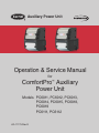
Auxiliary Power Unit
R
Operation & Service Manual
for
ComfortPro™ Auxiliary
Power Unit
Models PC6011, PC6012, PC6013,
PC6014, PC6015, PC6018,
PC6019
PC6111, PC6112
62--11175 Rev E
Models covered by this publication
6000 SERIES
Model #
PC6011
PC6012
PC6013
PC6014
PC6015
PC6018
PC6019
Description
Carrier 12K BTU Integrated APU
ComfortPro 12K BTU Integrated APU
ComfortPro 12K BTU Integrated APU with DPF
ComfortPro GENX APU Only
ComfortPro GENX 12K CCU with SHORE POWER
Carrier GENX APU ONLY
Carrier GENX 12K CCU with SHORE POWER
6100 SERIES
Model #
PC6111
PC6112
Description
Carrier 12K BTU Stand Alone APU
ComfortPro 12K BTU Standalone APU
CONTENTS
INTRODUCTION
SAFETY
Safety Alerts ................................................................................. c-iii
Component Layout.......................................................................... c-v
GENERAL ARRANGEMENT
APU Dimensions ............................................................................ c-vi
CCU Dimensions........................................................................... c-vii
Condenser Dimensions ................................................................. c-vii
1.0 OPERATION OF MULTI–FUNCTION D.C.P
1.1
PREPARATION
1.1.1 Multi–Function D.C.P Components....................................... 1-1
1.1.2 How the ComfortPro Operates ............................................. 1-2
1.2
MANUAL OPERATIONS
1.2.1 Starting the APU ................................................................ 1-5
1.2.2 Stopping the APU ............................................................... 1-5
1.2.3 Turning the Heater ON/OFF................................................. 1-5
1.2.4 Heating: Setting the Temperature ........................................ 1-6
1.2.5 Turning the A/C ON/OFF ..................................................... 1-6
1.2.6 Setting the A/C Temperature .............................................. 1-6
1.2.7 Fan Operation .................................................................... 1-6
1.3
AUTOMATIC OPERATIONS
1.3.1 Password Protection........................................................... 1-7
1.3.2 Entering Password ............................................................. 1-8
1.3.3 Setting the Clock ............................................................... 1-8
1.3.4 Comfort Monitor................................................................. 1-9
1.3.5 Timer .............................................................................. 1-10
1.3.6 Temp Start ...................................................................... 1-11
1.3.7 Maximum Run Time.......................................................... 1-12
1.3.8 Battery Monitoring............................................................ 1-13
2.0 CLIMATE CONTROL UNIT (CCU)
2.1
PREPARATION
2.1.1 Charging the CCU............................................................... 2-1
2.2
SERVICE
2.1.2 Maintenance Schedule ....................................................... 2-2
2.1.2 CCU Spring Tune–Up .......................................................... 2-3
3.0 TROUBLESHOOTING
3.0
3.1
3.2
3.3
3.4
3.5
3.6
3.7
62-11175 COMFORTPRO SERVICE MANUAL
MANUAL OPERATIONS
APU (Auxiliary Power Unit)............................................................... 3-2
GENERATOR .................................................................................. 3-6
DRIVER CONTROL PANEL ............................................................... 3-7
CCU AIR CONDITIONING ................................................................. 3-8
CCU Fan ..................................................................................... 3-11
CCU Heat.................................................................................... 3-11
RECEPTACLE PANEL..................................................................... 3-12
c-i
3.0 TROUBLESHOOTING (Cont.)
3.8
3.9
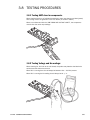
TESTING PROCEDURES
3.8.1 Testing AMP draw for components ....................................... 3-13
3.8.2 Testing Voltage and Hz readings .......................................... 3-13
ADDITIONAL INFORMATION
3.9.1 Adjusting the 120 A/C Voltage............................................. 3-14
3.9.2 Capacitor Troubleshooting ................................................... 3-14
3.9.3 Capacitor Theory................................................................. 3-14
3.9.4 Potential Relay Theory......................................................... 3-15
3.9.5 Alternator Troubleshooting................................................... 3-15
3.9.6 Fuel Solenoid Troubleshooting ............................................. 3-16
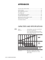
APPENDICES
CAPACITIES AND SPECIFICATIONS ........................................................... A-1
FUSE LOCATIONS ................................................................................... A-4
CIRCUIT BREAKER LOCATIONS ................................................................ A-5
APU CONTROL UNIT................................................................................ A-6
CCU CONTROLLER.................................................................................. A-7
FUEL SYSTEM PURGE PROCEDURE ......................................................... A-8
COOLANT PURGE PROCEDURE FOR INTEGRATED APU ............................... A-9
COOLANT FILL PROCEDURE FOR STAND-ALONE APU ................................. A-9
DEFROST/HEAT & DCP SENSOR............................................................ A-11
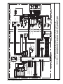
INTEGRATED APU WIRING DIAGRAM (30-864-50B) .................................. A-12
INTEGRATED APU WIRING DIAGRAM (30-864-50C) .................................. A-13
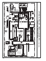
STAND-ALONE APU WIRING DIAGRAM (30-S64-01A) ................................ A-14
c-ii
62-11175 COMFORTPRO SERVICE MANUAL
SAFETY
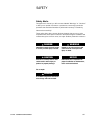
Safety Alerts
Throughout this manual, you will see notes labeled "Warnings" or "Cautions"
to alert you to special instructions or precautions concerning a particular
procedure that would be hazardous if performed incorrectly or carelessly.
Observe them carefully!
These safety alerts alone cannot eliminate hazards that can occur. Strict
compliance with these special instructions when performing the installation and
maintenance, plus common sense, are major accident prevention measures.
DANGER
Immediate hazards that will result
in severe personal injury or death.
CAUTION
Hazards or unsafe practices that
could result in minor injury or
product or property damage.
WARNING
Hazards or unsafe practices that
could result in severe personal
injury or death.
NOTICE
Information that is important to
proper installation or maintenance,
but is not hazard-related.
For example:
DANGER
A certified refrigeration technician
must charge and test the CCU.
62-11175 COMFORTPRO SERVICE MANUAL
c-iii
Safety Considerations
Exhaust
Inhalation of exhaust gas (containing carbon monoxide) may cause severe
personal injury and/or death. Anyone suspected of suffering from CO
inhalation should be removed from the hazardous area and given medical
assistance immediately.
WARNING
California Proposition 65 Warning: This product contains lead, a
chemical known to the State of California to cause cancer and birth
defects and other reproductive harm.
Fuel/Batteries
Exercise extreme caution when working near fuel or fuel-filled equipment.
Do not operate equipment during fueling operations. Use eye protection
when working near batteries, which contain acid and can explode. Do not
smoke or use open flames near batteries.
Electrical
Electric shock can cause severe personal injury, burns, and death. Before
working on any unit, disconnect the batteries. Use only approved materials
and methods when working on the electrical system, and follow local electrical
codes. Never work on the APU or the electrical circuitry when the APU is
running. Never work with electricity in wet conditions or when you are tired.
Toxic Substances
Fuel, oil, coolant, and refrigerant are toxic and in some cases, carcinogenic.
Wear eye and hand protection at all times. Remove contaminated clothing
immediately and wash contaminated skin. Do not breathe in vapors.
Hot or Moving Parts
Moving parts can cause severe injury and/or death. Before working on any
unit, shut it off and disconnect the battery. Do not start until protective covers
have been replaced. Also, loose parts falling into rotating machinery can
cause severe accidents. Always ensure bolts and clamps are correctly
torqued and secured. Inspect mechanical components periodically for
damage, corrosion, and proper torque.
Misuse
The APU is designed to provide electrical power for heating and cooling
vehicles in normal on-road conditions. Never use the APU to power critical
medical equipment or sensitive electronic equipment without the
manufacturer's express written approval.
Warnings/Cautions
MUST be observed
WARNING
DO NOT start the APU when the
enclosure cover is removed.
Operating with the cover off may
result in injury and/or death.
WARNING
When the APU is about to start, a
buzzer sounds. Make sure no one is
standing near the APU or touching it.
WARNING
Charging the CCU must be performed by
a certified air conditioning technician
who has experience with hermetic
systems and Refrigerant R-134A.
WARNING
Vapor charge CCU only.
WARNING
Before undertaking ANY repair to
the APU, CCU or component of the
ComfortPro system disconnect the
batteries from the APU.
c-iv
62-11175 COMFORTPRO SERVICE MANUAL
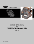
COMPONENT LAYOUT
The main components of the
ComfortPro are the Auxiliary
Power Unit (APU), the Climate
Control Unit (CCU) and the Driver
Control Panel (DCP).
BATTERY
CHARGER
DRIVER CONTROL
PANEL (DCP)
Note: In this manual, the term
DCP refers generically to all
models of Driver Control Panel,
including DCP, DCP2, etc.
SHORE POWER
MANAGER
115V SHORE
POWER PLUG
CONDENSER
Optional Shore Power
120 VAC
RECEPTACLE PANEL
CLIMATE CONTROL
UNIT (CCU)
BATTERY
FUEL SUPPLY
AND RETURN
AUXILIARY POWER UNIT (APU)
VEHICLE FUEL TANK
COOLANT SUPPLY
AND RETURN
Figure C1: Main Components of the Carrier ComfortPro Integrated APU system and where they should best be installed on the truck.
DRIVER CONTROL
PANEL (DCP)
115 VAC
RECEPTACLE
PANEL
CONDENSER
CLIMATE CONTROL
UNIT (CCU)
SURGE TANK
FOR RADIATOR
BATTERY
AUXILIARY POWER UNIT (APU)
WITH RADIATOR IN REAR
FUEL SUPPLY
AND RETURN
VEHICLE FUEL TANK
OUTLET FOR
BLOCK HEATER
Figure C2: Main Components of the Carrier ComfortPro Stand Alone APU system and where they should best be installed on the truck.
62-11175 COMFORTPRO SERVICE MANUAL
c-v
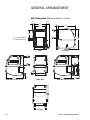
GENERAL ARRANGEMENT
APU Dimensions (Measurements in inches)
3.875
2.75
18.5
2.6
24.9
16.0
10.5
X = 1.9 STAND-ALONE APU
X = 3.0 INTEGRATED APU
X
28.5
REAR
LEFT SIDE
13.4
24.9
RIGHT SIDE (INTEGRATED APU)
24.9
2.6
FRONT VIEW
11.5
RIGHT SIDE (STAND-ALONE APU)
TOP VIEW
c-vi
62-11175 COMFORTPRO SERVICE MANUAL
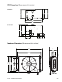
CCU Dimensions (Measurements in inches)
FRONT VIEW
12.6"
12"
7.9"
12.9"
.125"
23.4"
24.4"
BOTTOM VIEW
3.0"
16.2"
15.2"
6.9"
3.0"
3.0"
3.3" 3.1"
6.9"
3.0"
3.4"
1.3"
Condenser Dimensions (Measurements in inches)
26.5"
8"
3.5"
24.25"
2.0"
13.93"
16.25"
16.90"
5.62"
5.62"
DOWN
FRONT
62-11175 COMFORTPRO SERVICE MANUAL
RIGHT SIDE
c-vii
c-viii
62-11175 COMFORTPRO SERVICE MANUAL
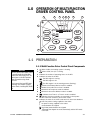
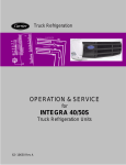
1.0 OPERATION OF MULTI-FUNCTION
DRIVER CONTROL PANEL
4
5
6
7
8
10
9
11
3
APU
ON/OFF
HOURS
00000
T1 T2 SP
APU
HVAC
OFF
2
ESC/
RESET
MENU
A/C
FAN
HEAT
1
Figure 1-0: Multi-Function Driver Control Panel
1.1 PREPARATION
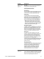
1.1.1 Multi-Function Driver Control Panel Components
NOTICE
The DCP (driver control panel), which
is mounted inside the truck bunk,
controls the APU and the CCU. The
central panel on the DCP provides
status information using words
and icons.
In this manual, the term DCP refers
generically to all models of Driver
Control Panels, including DCP, DCP2,
etc.
1
2
When visible, the heating system is heating.
When visible, the A/C is cooling.
3 Indicates the number of operating hours on the APU.
4 Indicates the state of the APU.
APU The APU engine is running.
S
APU
The APU engine is off.
APU The APU engine is in the starting process (flashing).
5
Indicates that Battery Monitor mode is enabled.
6
Indicates that maximum run time is enabled.
7
Indicates that Temp Start mode is enabled.
8
9
10
Indicates that Comfort Monitor mode is enabled.
T1 T2 Indicates that Timer 1 or Timer 2 mode is enabled.
SP Indicates that the ComfortPro is connected to shore power.
The APU cannot be started in Shore Power mode.
11 Indicates the state of the 115V outlet and CCU auto-reset breakers.
115 VAC power is being supplied to the outlet.
OFF
No power is being supplied to the outlet.
TRIP
Outlet breaker has tripped.
TRIP High Heat/Outlet breaker has tripped.
RESET The breaker that tripped has reset automatically and the DCP needs
to be reset.
62-11175 COMFORTPRO SERVICE MANUAL
1-1
1.1.2 How the ComfortPro Operates
The ComfortPro has two modes of operation: manual and automatic.
Manual Mode
You start the APU from within the truck bunk using the APU On/Off button
on the driver control panel (DCP). Once the APU is running, you can start
and stop the fan, heater and air conditioning using the DCP. See page 1-5.
Once the heater or A/C is running, it will cycle (automatically turn on and off)
in order to keep the truck bunk at the temperature you specify. The HVAC will
continue to cycle until you turn it off. While the HVAC is cycling, the APU
remains on and will only turn off when you manually turn it off using the button on
the DCP.
Note that in manual mode, the APU remains on until you turn it off. But in
Comfort Monitor mode (described below), the APU automatically turns off
and on as required.
When the APU is running, power is supplied to the power outlet in the
truck bunk (except in high heat).
In manual mode, the APU will turn off automatically if the Maximum Run
Time is reached.
Automatic Mode
The ComfortPro has several functions that will start it in automatic mode.
FEATURE
DESCRIPTION
Comfort Monitor
(page 1-9)
Comfort Monitor is intended to maintain the truck cabin
temperature at a desired set point by cycling both the APU
and HVAC on and off as required. While operating in
Comfort Monitor mode, the HVAC will only operate at high
output settings, i.e. either High Heat or High A/C.
MENU ITEMS AND PASSWORD PROTECTION
Comfort Monitor is one of the main items in the DCP/DCP2
menu tree and may be password protected independently of
the other main menu items. Within the Comfort Monitor
menu, three settings are available:
ON/OFF: Allows the user to enable or disable the Comfort
Monitor feature.
Note: Comfort Monitor Mode and Manual APU operation
are mutually exclusive, i.e.
An ON setting enables CM mode and disables Manual
APU operation.
An OFF setting disables CM mode and enables Manual
APU operation.
SET DURATION: Allows the user to set the maximum
session time that the APU can remain in Comfort Monitor
mode. The duration timer may be set between 0.0 HRS to
24.0 HRS in increments of 0.5 HRS.
Note: A duration setting of 0.0 HRS will restore the earlier
Comfort Monitor functionality. In this configuration, Comfort
Monitor cannot be de-activated by the operator. Comfort
Monitor can only be enabled via the menu settings
(typically subject to password protection).
Specifically: The operator cannot activate / de-activate
Comfort Monitor using the ON/OFF key (see below).
The CM icon stays visible on the display.
When used with an engine interlock, Comfort Monitor
operation will automatically re-activate when the main
engine is turned off. The CM icon disappears while the
main engine is running.
The operator has the ability to enter and exit manual mode.
1-2
62-11175 COMFORTPRO SERVICE MANUAL
FEATURE
DESCRIPTION
Comfort Monitor
Cont.
(page 1-9)
SET TEMP:
Allows the user to set the desired ambient temperature in
the range from 18°C (64°F) to 30°C (86°F).
COMFORT MONITOR OPERATION
APU ON/OFF key
With Comfort Monitor enabled and its duration timer set to
a non-zero value in the menu, the APU ON/OFF key may be
used to activate / de-activate Comfort Monitor mode.
Duration Timer
The Comfort Monitor session duration timer begins
counting down from its set value each time that Comfort
Monitor mode is activated via the APU ON/OFF key. When
the timer has elapsed, Comfort Monitor mode will deactivate. The driver may re-activate Comfort Monitor for a
new session if desired by pressing the APU ON/OFF key.
Note: The intent is that the driver should de-activate
Comfort Monitor when leaving the truck for a period of
time in which comfort monitor is not required. If Comfort
Monitor is not manually de-activated, it will continue to
operate until the duration timer has expired.
Other Control Panel Keys
The MENU, ESC/RESET and ARROW keys may continue to
be used for accessing and navigating the menu. The balance
of front panel keys, including HVAC OFF, A/C, FAN, and
HEAT, have no associated functionality while the system
operates in Comfort Monitor. Additionally the ARROW Keys
may not be used to adjust the temperature set point.
APU Interlock
This applies only to APUs equipped with main engine
interlocks. If the APU has Comfort Monitor enabled, and the
main engine interlock activates to signal that the main
engine has started and is running, then Comfort Monitor
will be de-activated. Additionally, Comfort Monitor cannot
be activated with an active engine interlock.
If desired, the driver may re-activate Comfort Monitor for a
new session by pressing the APU ON/OFF key, but only after
the main engine interlock has de-activated, i.e. the main
engine has shut off.
Other Automatic Modes
If enabled in the menu, other automatic modes may become
active while the APU operates in Comfort Monitor mode.
Activation of any of the other automatic modes will
temporarily override Comfort Monitor, however APU
operation will return to Comfort Monitor mode if all
automatic mode duration timers have expired but the
Comfort Monitor duration timer has not expired.
Timer
(page 1-10)
62-11175 COMFORTPRO SERVICE MANUAL
At the specified time, the APU and HVAC automatically
turn on. During the specified timer duration, the HVAC
cycles on and off to maintain the desired temperature.
When the timer duration expires, both the APU and
HVAC turn off automatically and remain off.
1-3
Temp Start
(page 1-11)
The APU and heater on the HVAC automatically turn on
in order to prevent the APU engine and truck engine
from getting too cold. (Turning on the heater creates a
“load” that makes the APU work harder and therefore
warm up faster). Both the APU and HVAC turn off
automatically once the preset duration time expires.
Battery Monitor
(page 1-13)
The APU automatically turns on for 90 minutes in order
to recharge the batteries. The HVAC does not turn on.
After the 90 minute run time, the system will sense
voltage for 10 minutes, before restarting if needed.
There are icons on the DCP that flash when the APU and HVAC are running.
See page 1-1. If you enter the truck bunk and APU or HVAC is on but you
did not start it, you can assume it has started in one of the automatic
modes, as described above. On the DCP, one icon will be flashing steadily:
this is the icon for the mode that is currently operating.
Whenever the ComfortPro is running in automatic mode (except for
Comfort Monitor mode), if you then press the heat, A/C or fan buttons on
the DCP, the ComfortPro will switch to manual mode. The APU will not
automatically turn off! This icon on the DCP will also stop flashing.
When the ComfortPro is operating in Comfort Monitor mode, manual APU
operation is locked out.
Automatic Mode and Minimum Time Off
All these automatic functions work on a "minimum time off": the
ComfortPro must be off for at least 10 minutes before the automatic
function will turn it on again. For example, the Timer function may be set
to turn on the ComfortPro at 10:00 a.m. You have been running the
ComfortPro in manual mode. You turn off the ComfortPro at 9:55 a.m. The
timer will only turn on the ComfortPro again 10 minutes later, at 10:05
a.m.
Clock
In order to use the Timer correctly, you must set the DCP clock. See page 1-8.
Maximum Run Time
You can set the maximum time that the APU is allowed to continuously run
in manual mode. See page 1-12.
Password Protection
You can add a password to the DCP, then you can protect one or more
functions so that only a person who knows the password can set the
function. See page 1-7.
1-4
62-11175 COMFORTPRO SERVICE MANUAL
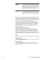
1.2 MANUAL OPERATIONS
1.2.1 Starting the APU "One Touch Start"
WARNING
Do not start the APU when the enclosure
cover is removed. Operating with the
cover off may result in injury and/or death.
WARNING
When the APU is about to start, a buzzer
sounds. Make sure no one is standing
near the APU or touching it.
Press and release
once.
HOURS
00000
The display shows "PLEASE WAIT – APU
STARTING" and APU flashes.
When APU stops flashing, then the APU
has started
successfully.
S
The APU startup sequence consists of
20 seconds of glowing (30 seconds when
the ambient temperature is below -5°C or
23°F) and up to 10 seconds of cranking.
If the sequence fails, "RESTARTING"
appears for six seconds. Then the
startup sequence automatically repeats
up to five times or until the APU starts.
APU
OFF
PLEASE WAIT
APU STARTING
HOURS
00000
APU
OFF
RESTARTING
HOURS
00000
If "CRANK LIMIT" appears, see
Troubleshooting section.
APU
OFF
CRANK LIMIT
1.2.2 Stopping the APU
Press
.
The APU will stop. The display
shows APU .
HOURS
00000
APU
OFF
Make sure to shut down HVAC before
stopping APU!
1.2.3 Turning the Heater ON/OFF
NOTICE
The heat mode will not function if the
temperature is higher than 29.5°C (85°F).
1 Press
to activate the heater.
The display shows "HEAT LOW".
The heater will turn on only if the
temperature is too low (to adjust the
temperature, see below). When the
heater is on,
appears.
2 Press
again to switch between
high and low heat to heat the truck
bunk more or less quickly. In "HEAT
HIGH" mode, the power outlet is
disabled and the display indicates OFF .
The heat will turn off when the desired
temperature is reached.
3 Press
62-11175 COMFORTPRO SERVICE MANUAL
HOURS
00000
APU
HEAT LOW
C
H
HOURS
00000
APU
OFF
HEAT HIGH
C
H
to deactivate heating.
1-5
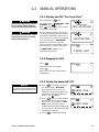
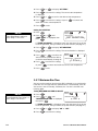
1.2.4 Heating: Setting the Temperature
Press
or
HIGH" shows).
when the heater is on ("HEAT LOW"or "HEAT
The notch on the temperature bar moves. The heater will automatically
turn on and off to maintain this temperature.
1.2.5 Turning the A/C ON or OFF
NOTICE
The air conditioning function will not
operate if the temperature is lower
than 18.5°C (65°F).
1 Press
to activate the A/C.
The display shows "A/C LOW".
The A/C will turn on only if the
temperature is too high (to adjust the
temperature, see below). When the
A/C is on,
appears.
2 Press
again to switch between
high and low A/C to cool the truck
bunk more or less quickly.
3 Press
HOURS
00000
APU
A/C LOW
C
HOURS
00000
H
APU
to deactivate the A/C.
A/C HIGH
C
H
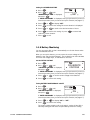
1.2.6 A/C Setting the Temperature
Press
or
when the A/C is on ("A/C LOW" or "A/C HIGH" shows).
The notch on the temperature bar moves. The A/C will automatically turn
on and off to maintain this temperature.
1.2.7 Fan Operation
You can still have the fan working even when the temperature is not low or
high enough for the heat or A/C to come on.
The fan operation is independent of the air conditioning and heat modes.
When the fan speed is manually set to high or low, the fan will return to
that setting when the desired temperature has been reached as the air
conditioning or heat cycles off.
Press
to toggle between low,
high and off.
The speed of the fan may automatically
change when the heat or A/C comes on,
then automatically change back when
the heat or A/C goes off.
HOURS
00000
APU
FAN
LOW
C
HOURS
00000
H
APU
FAN
HIGH
C
1-6
H
62-11175 COMFORTPRO SERVICE MANUAL
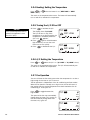
1.3 AUTOMATIC OPERATIONS
1.3.1 Password Protection
WARNING
Once Automatic functions are set the
system could start at anytime. Before
servicing the unit be sure to disconnect
the unit from the batteries to prevent
injury should the unit attempt to start
while servicing. All presets will remain
once battery cable is reconnected.
You can add a password to the DCP, then you can protect one or more
functions so that only a person who knows the password can set the function.
On a newly installed DCP, the password is always 000, which means that
no password protection is in place.
To password-protect functions, first change the factory password; see
'Setting up for Password Protection'. All functions will now be password
protected. Then remove password protection from chosen functions, as
desired; see 'Protect Functions with a Password'.
If you know the password, you can change it at any time, if you need to.
Note that if you change the password to 000, you will remove password
protection from all functions.
If the password is ever lost, contact your dealer to have the password
reset to 000.
Setting up for PASSWORD PROTECTION
1 Press
.
2 Press
or
then press
until "SET/CHANGE PASSWORD" is displayed,
.
"ENTER PASSWORD" is displayed
with three blank squares, one for
each digit in the password. The
first digit flashes.
3 Press
or
HOURS
00000
APU
OFF
ENTER PASSWORD
000
until the first number in the password is displayed.
For example, if your password is "432" press
then press
.
until "4" shows,
4 Repeat for each digit in the password.
5 Press
again after entering the last digit. "NEW PASSWORD"
is displayed.
6 Repeat the above steps to enter the new password. "CONFIRM"
is displayed.
7 Enter the new password again, then press
to exit this function.
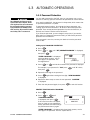
PROTECT FUNCTIONS with a PASSWORD
1 Press
.
2 Press
or
until
"PASSWORD PROTECT"
is displayed, then press
.
If this menu item does not appear,
then you have not yet changed the
factory password from 000. Change
the password and then try again.
HOURS
00000
APU
OFF
PASSWORD
PROTECT
"ENTER PASSWORD" is displayed with three blank squares, one for
each digit in the password. The first square flashes.
62-11175 COMFORTPRO SERVICE MANUAL
1-7
3 Press
or
until the first number in the password is
displayed, then press
.
4 Repeat for each digit in the password.
5 Press
again after entering the last digit.
The first feature that can be password protected is displayed with
"YES" or "NO" (indicating whether it is currently password protected).
6 Press
or
7 Press
to move to the next feature.
Or press
to change the "YES" or "NO".
or
to skip to the next feature.
1.3.2 Entering the Password
When you try to set up a function, you may be prompted to enter the password.
1 Press
or
until the first number in the password
is displayed, then press
.
2 Repeat for each digit in the password.
3 Press
again after entering the last digit.
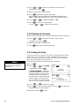
1.3.3 Setting the Clock
NOTICE
The clock does not automatically
adjust for time zone changes; you
must adjust it.
You can set the clock on the DCP. This clock is used by the Timer function
(page 1-10). If you use the Timer function, remember that as you move
from one time zone to another, you must adjust the clock. Otherwise the
Timer will start the APU at the wrong time.
The clock settings remain even when the APU is turned off.
1 Press
2 Press
.
or
until "CLOCK"
is displayed, then press
or
APU
.
If "ENTER PASSWORD" is displayed,
enter your password. If you do not
know the password, then you cannot
set up this function (see page 1-7).
The clock function takes you through
several settings: 12/24-hour-clock,
hour set, minutes set, am/pm-set (for
12-hour clock only), and day of the week.
3 Press
HOURS
00000
CLOCK
HOURS
00000
APU
CLOCK: SET MODE
12 HOUR
to change the setting.
4 Press
to move to the next setting. Or press
changes you have not yet accepted.
5 When done, press
1-8
OFF
to cancel any
to exit.
62-11175 COMFORTPRO SERVICE MANUAL
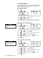
1.3.4 Comfort Monitor
You can specify the temperature you want in the truck bunk. Whenever the
truck bunk temperature goes 2° above or below this temperature, the APU
starts and the HVAC turns on until that temperature is reached or for
fifteen minutes, whichever is longer.
Enabling COMFORT MONITOR
1 Press
.
2 Press
or
until
"COMFORT MONITOR" is displayed,
then press
.
HOURS
00000
APU
COMFORT MONITOR:
ON
If "ENTER PASSWORD" is displayed,
enter your password. If you do not
know the password, then you cannot set up this function (see page 1-7).
3 Press
or
to display "ON" or "OFF".
4 Press
to confirm this setting.
The current setting remains until you change it; turning off the APU or
manually starting the APU does not permanently cancel this setting.
Setting the Comfort Monitor TEMPERATURE
NOTICE
Factory Default Temperature Setting is
21°C (70°F). Range is 18°C (64°F) to
30°C (86°F).
1 Press
HOURS
00000
.
2 Press
or
until
"COMFORT MONITOR" is displayed,
then press
.
APU
COMFORT MONITOR
SET TEMP
If "ENTER PASSWORD" is displayed, enter your password. If you do not
know the password, then you cannot set up this function (see page 1-7).
3 Press
or
to display "SET TEMP".
4 Press
to confirm this setting. The current temperature is displayed.
5 Press
or
to scroll to the desired temperature.
6 Press
to confirm this setting. Or press
retain the current temperature.
7 Press
to cancel and
to exit.
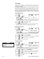
Setting the DURATION in Comfort Monitor
NOTICE
Factory Default Duration Setting is 8
hours. Range is 0 hours to 24 hours
(in 0.5 hour increments).
1 Press
.
HOURS
00000
2 Press
or
until
"COMFORT MONITOR" is displayed,
then press
.
APU
COMFORT MONITOR
SET DURATION
If "ENTER PASSWORD" is displayed, enter your password. If you do not
know the password, then you cannot set up this function (see page 1-7).
3 Press
or
to display "SET DURATION".
4 Press
to confirm this setting. The current duration is dispalyed.
5 Press
or
to scroll to the desired duration.
6 Press
to confirm this setting. Or press
retain the current duration.
7 Press
62-11175 COMFORTPRO SERVICE MANUAL
to cancel and
to exit.
1-9
1.3.5 Timer
You can set up the ComfortPro so that the APU and CCU run automatically for
a specified time on specified days of the week. There are two timers, so you
can set up two schedules.
For example, one schedule may be to run every day at 6:00 p.m. for .5 hours
and the other schedule may be to run every Monday at 6.00 a.m. for .5 hours.
You must set up the timer as follows: Specify the day and time you want
the APU to run, specify the duration (the length of time you want the APU to
run for) and specify the temperature you want maintained in the truck bunk
while the APU is running.
Turning TIMER On or Off
1 Press
HOURS
00000
.
2 Press
or
until
"TIMER 1" or "TIMER 2" is displayed,
then press
.
APU
T1
OFF
TIMER 1
ON
If "ENTER PASSWORD" is displayed, enter your password. If you do not
know the password, then you cannot set up this function (see page 1-7).
3 Press
or
to display "ON" or "OFF".
4 Press
to confirm this setting.
The current setting remains until you change it; turning off the APU or
manually starting the APU does not cancel the timer function.
Setting the Start Time/Day
1 Press
.
HOURS
00000
2 Press
or
until
"TIMER 1" or "TIMER 2" is displayed,
then press
.
APU
T1
OFF
TIMER 1
SET START
If "ENTER PASSWORD" is displayed, enter your password. If you do not
know the password, then you cannot set up this function (see page 1-7).
3 Press
or
to display "SET START".
4 Press
to confirm this setting. The current start time is displayed.
5 Press
or
6 Press
to confirm each setting.
to set the hours, minutes and day.
Setting the DURATION
NOTICE
Factory Default Duration Setting is 1 hour.
Range is 0.5 hrs - 10 hrs (in 0.5 hr
increments).
1 Press
.
HOURS
00000
2 Press
or
until
"TIMER 1" or "TIMER 2" is displayed,
then press
.
APU
T1
OFF
TIMER 1
SET DURATION
If "ENTER PASSWORD" is displayed, enter your password. If you do not
know the password, then you cannot set up this function (see page 1-7).
3 Press
or
to display "SET DURATION".
4 Press
to confirm this setting. The current duration time is displayed.
5 Press
or
to scroll to the length of time to run the APU.
6 Press
to confirm this setting. Or press
retain the current duration.
7 Press
1-10
to cancel and
to exit.
62-11175 COMFORTPRO SERVICE MANUAL
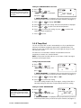
Setting the TEMPERATURE for the Timer
NOTICE
Factory Default Temperature Setting is
21°C (70°F). Range is 18°C (64°F) to
30°C (86°F).
1 Press
.
HOURS
00000
2 Press
or
until
"TIMER 1 or TIMER 2" is displayed,
then press
.
APU
T1
OFF
TIMER 1
SET TEMP
If "ENTER PASSWORD" is displayed, enter your password. If you do not
know the password, then you cannot set up this function (see page 1-7).
3 Press
or
to display "SET TEMP".
4 Press
to confirm this setting. The current temperature is displayed.
5 Press
or
to scroll to the desired temperature.
6 Press
to confirm this setting. Or press
retain the current temperature.
7 Press
to cancel and
to exit.
1.3.6 Temp Start
You can set up the APU so that it automatically runs for a specified time
whenever the ambient temperature goes below a specified value. This
feature ensures that the APU engine and truck engine do not get so cold
that they will not start.
This feature is not intended to maintain a comfortable truck bunk
temperature; instead, see “Comfort Monitor”.
NOTE: In Temp Start the HVAC will turn on the heat to 'LOAD' the engine
and warm up the engine faster.
Turning Temp Start On and Off
1 Press
.
HOURS
00000
2 Press
or
until
"TEMP START" is displayed, then
press
.
APU
OFF
TEMP START
ON
If "ENTER PASSWORD" is displayed, enter your password. If you do not
know the password, then you cannot set up this function (see page 1-7).
3 Press
or
to display "ON" or "OFF".
4 Press
to confirm this setting.
The current setting remains until you change it; turning off the APU or
manually starting the APU does not permanently cancel this setting.
Setting the START TEMPERATURE
NOTICE
Factory Default Temperature Setting
-10°C (14°F). Range is -20°C (-4°F) to
5°C (41°F).
1 Press
.
2 Press
or
until
"TEMP START" is displayed, then
press
.
HOURS
00000
APU
OFF
TEMP START : SET TEMP
-10C 14F
If "ENTER PASSWORD" is displayed, enter your password. If you do not
know the password, then you cannot set up this function (see page 1-7).
62-11175 COMFORTPRO SERVICE MANUAL
1-11
3 Press
or
to display "SET TEMP".
4 Press
to confirm this setting. The current start temperature
is displayed.
5 Press
or
to scroll to the desired start temperature.
to confirm this setting. Or press
6 Press
retain the current start temperature.
7 Press
to cancel and
to exit.
Setting the DURATION
NOTICE
Factory Default Duration Setting is 2
hours. Range is 1 hr to 4 hrs.
1 Press
HOURS
00000
.
2 Press
or
until
"TEMP START" is displayed, then
press
.
APU
OFF
TEMP START
SET DURATION
If "ENTER PASSWORD" is displayed, enter your password. If you do not
know the password, then you cannot set up this function (see page 1-7).
3 Press
or
to display "SET DURATION".
4 Press
in hours.
to confirm this setting. The current duration is displayed
5 Press
or
to scroll to the
amount of time you want the APU to
run before automatically shutting off.
6 Press
APU
OFF
TEMP START : DURATION
1.0 hrs
to confirm this setting.
Or press
7 Press
HOURS
00000
to cancel and retain the current start temperature.
to exit.
1.3.7 Maximum Run Time
You can set the maximum time that the APU is allowed to run continuously.
If the APU runs for longer than the specified time, it automatically shuts off.
You can then start it manually, if desired; the "run time" clock will start
counting again.
Turning MAXIMUM RUN TIME ON OR OFF
NOTICE
Factory Default Run Time Setting is 8
hours. Range is 2 to 24 hours.
1 Press
HOURS
00000
.
2 Press
or
until
"MAXIMUM RUN TIME" is displayed,
then press
.
APU
MAXIMUM RUN TIME
ON
If "ENTER PASSWORD" is displayed, enter your password. If you do not
know the password, then you cannot set up this function (see page 1-7).
1-12
3 Press
or
to display "ON" or "OFF".
4 Press
to confirm this setting.
62-11175 COMFORTPRO SERVICE MANUAL
Setting the DESIRED RUN TIME
1 Press
HOURS
00000
.
2 Press
or
until
"MAXIMUM RUN TIME" is displayed,
.
then press
APU
MAXIMUM RUN TIME
SET
If "ENTER PASSWORD" is displayed, enter your password. If you do not
know the password, then you cannot set up this function (see page 1-7).
3 Press
or
to display "SET".
4 Press
to confirm this setting.The current duration is displayed.
5 Press
or
to scroll to the desired number of hours.
6 Press
to confirm this setting. Or press
retain the current duration.
7 Press
to cancel and
to exit.
1.3.8 Battery Monitoring
You can set up the APU so that it automatically runs for 90 minutes when
the truck batteries are low.
When you set up this feature, you must enter the current voltage of the
batteries (see “Set the Initial Voltage”). The ComfortPro can then calculate
how much the voltage drops, as the batteries are used.
Set the INITIAL VOLTAGE
1. Press
HOURS
00000
.
2 Press
or
until
"CALIBRATE VOLTAGE" is displayed,
then press
.
APU
OFF
CALIBRATE
VOLTAGE
If "ENTER PASSWORD" is displayed, enter your password. If you do not
know the password, then you cannot set up this function (see page 1-7).
3 Press
or
to set the current voltage of the batteries.
4 Press
to confirm this setting.
Turning BATTERY MONITORING ON and OFF
1 Press
.
HOURS
00000
2 Press
or
until
"BATTERY MONITOR" is displayed,
then press
.
APU
OFF
BATTERY MONITOR
ON
If "ENTER PASSWORD" is displayed, enter your password. If you do not
know the password, then you cannot set up this function (see page 1-7).
3 Press
or
to display "ON" or "OFF".
4 Press
to confirm this setting.
The current setting remains until you change it; turning off the APU or
manually starting the APU does not permanently cancel this setting.
62-11175 COMFORTPRO SERVICE MANUAL
1-13
The APU starts if the battery voltage goes below the level you specify here.
Setting the Voltage Level
NOTICE
Factory Default Voltage Setting is 11.8V.
Range is 11.0V to 13.5V.
1 Press
HOURS
00000
.
APU
OFF
BATTERY MONITOR : SET
or
until
2 Press
"BATTERY MONITOR" is displayed,
then press
.
11.8 V
If "ENTER PASSWORD" is displayed, enter your password. If you do not
know the password, then you cannot set up this function (see page 1-7).
3 Press
NOTICE
APU will not start until battery voltage
has been below the specified level for
10 minutes.
to display "SET".
4 Press
to confirm this setting. The current voltage level is
displayed and flashes.
5 Press
or
to scroll to the desired voltage.
6 Press
to confirm this setting. Or press
retain the current voltage.
7 Press
1-14
or
MENU
to cancel and
to exit.
62-11175 COMFORTPRO SERVICE MANUAL
2.0 CLIMATE CONTROL UNIT (CCU)
2.1 PREPARATION
WARNING
This procedure must be performed by
a certified air conditioning technician
who has experience with hermetic
systems and Refrigerant R-134A.
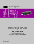
2.1.1 Charging the CCU
1
Pressure test the system for leaks with nitrogen.
2
Vacuum all the nitrogen for a minimum of 30 minutes to 500 microns.
3
With the high and the low side valves open, charge the system with
R-134A vapor to break the vacuum. Once the scale stabilizes and the
high and the low side pressures match, close the high side valve.
4
With only the low side valve open, start the A/C compressor by
selecting High A/C (APU Running). If needed lower the temperature
set point to start the A/C compressor.
5
Continue charging the system with vapor, on the low side only, until a
total of 50–55 oz of R-134A refrigerant has
been added as measured by the scale.
CONDENSER
CAUTION
Vapor charge CCU only.
NOTICE
Refrigerant Recovery:
Venting of refrigerant is against
the law and subject to fines and
loss of certification.
EPA regulations require that all
CFC and HCFC refrigerants be
recovered before any system can
be opened for service.
Recovery of refrigerant is done
using a certified recovery unit.
• Before a refrigeration system
can be opened to make repairs.
• Before pressurizing the system
with nitrogen for leak testing.
• Before disposing of any system or
component containing refrigerants.
• When it is necessary to remove
excess charge from an
overcharged system.
NOTICE
The air conditioning system has a 5
minute delay timer (minimum time
between cycles is 5 minutes).
LOW
HIGH
RED
BLUE
CCU
NOTICE
Total System Capacity is 50–55 oz.
A scale must be used to measure the
refrigerant weight. No other method
is acceptable. Failure to follow this
procedure exactly will result in
improper air conditioning function.
62-11175 COMFORTPRO SERVICE MANUAL
SCALE 50–55 OZ
Figure 2- 1: Connecting hoses to CCU to Condenser
2-1
2.2 SERVICE
2.2.1 Service/Preventive Maintenance Schedule
Interval between checks (in hours of operation)
Change oil and oil filter
Check fuel hoses, fuel pipes, and clamps
Check fasteners, muffler clamps and frame grippers
Check battery cable connections
Check coolant hoses and clamps
Check all belts for tension, alignment & condition
Check APU air filter, clean or replace as necessary
Change Alternator belt regardless of condition
Change fuel filters
Change Integrated APU Generator belt
Change Stand-Alone APU Generator belt regardless of condition every 3000 hours
Adjust valve lash
Clean inside enclosure
Clean radiator fins
Clean condenser fins
Check fuel hoses and clamps for abrasion and damage.
Change as necessary
Check CCU air filter, clean or replace as necessary. To clean, remove the mesh
filter and vacuum or wash (soap and water). Shake dry and reattach.
Check injection nozzle opening pressure
Check injection pump timing
Check water pump performance
Check alternator performance
Check starter performance
Check air conditioning performance (HVAC)
Check heater performance (HVAC)
Check generator line voltage
Check coolant hoses and clamps (from APU to main engine on Integrated APU,
from APU to radiator surge tank on Stand-Alone APU)
Check engine thermostat
Check air intake hose and clamps on APU
Drain and replace long-life coolant every 2 years
2-2
First
50
x
x
x
x
x
x
500
Every
1000 2000
x
x
x
x
x
x
x
x
x
x
x
x
x
x
x
x
x
x
x
x
x
x
x
x
x
x
x
62-11175 COMFORTPRO SERVICE MANUAL
2.2.2 CCU Spring Tune-Up
Purpose:
Recommended service and maintenance:
• Condenser.
• Air ducting and outlets.
• Evaporator and temperature sensor.
• Refrigerant lines connections and routing.
• Harness Connections and wiring.
• A/C operating efficiency - charge level.
Frequency:
Annually – preferably in the spring for the coming A/C season.
Recommended
Service Actions:
1
Check the condenser for:
Damage, leakage and/or contaminated fins that may restrict air flow.
2
Check air ducting and outlets for:
Damage and/or restrictions.
3
Check electrical harnesses for:
Tight connections and harness abrasions.
4
Check the evaporator for:
• Intake filter cleanliness, clean if required.
• Damaged and/or contaminated fins that may restrict air flow.
• Refrigerant leaks indicated by wet spots or dark stains on the evaporator
fins and connections.
• Check evaporator temperature sensor for proper function (see chart).
COMFORTPRO CCU EVAPORATOR DEFROST SENSOR TEMPERATURE – RESISTANCE CHART
160
150
140
130
120
kOhm
110
77°F, 100 kOhm
100
90
80
70
60
50
40
30
20
60
65
70
75
80
85
90
95
100
105
110
115
120
TEMPERATURE (°F)
5
62-11175 COMFORTPRO SERVICE MANUAL
Check the Refrigerant lines and connections for:
• Abrasion and wear points.
• Connection wet spots that may indicate refrigerant leakage.
2-3
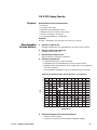
6
Check the refrigerant charge level:
• Install the A/C gauges as shown in the ComfortPro Installation
Manual. Operate the A/C on high.
• Refer to chart below for high and low reference pressure.
COMFORTPRO AIR CONDITIONING OUTDOOR AMBIENT TEMPERATURE AND
PRESSURE CHART
OUTDOOR TEMPERATURE
70°F
95°F
110°F
SUCTION PRESSURE
20 PSI
35 PSI
45 PSI
DISCHARGE PRESSURE
110 PSI
175 PSI
225 PSI
OVERALL CURRENT
Note: A/C - High
Measure at 120 volt teck cable
FAN ONLY AMP READING
FAN LOW
FAN HGH
5-9 AMPS
9-12 AMP 12-15 AMP
1.2-1.5 AMP
1.8-2.2 AMP
If both suction and discharge pressure is lower than the chart,
the system is undercharged.
If both suction and discharge pressure is higher than the chart,
the system is overcharged.
If level is not ok, recover and recharge the A/C system with the
correct amount of refrigerant as shown on page 2-1.
7
2-4
Check the CCU drain:
For damage and that it operates correctly.
62-11175 COMFORTPRO SERVICE MANUAL
3.0 TROUBLESHOOTING
WARNING
Before undertaking ANY repair to
the APU, CCU or component of the
ComfortPro system disconnect
the batteries from the APU.
3.1 APU (AUXILIARY POWER UNIT) .....................................................3-2
3.2 GENERATOR...............................................................................3-6
3.3 DRIVER CONTROL PANEL ............................................................3-7
3.4 CCU AIR CONDITIONING ..............................................................3-8
3.5 CCU FAN ..................................................................................3-11
3.6 CCU HEAT ................................................................................3-11
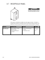
3.7 RECEPTACLE PANEL .................................................................3-12
3.8 ADDITIONAL INFORMATION........................................................3-13
62-11175 COMFORTPRO SERVICE MANUAL
3-1
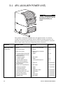
3.1 APU (AUXILIARY POWER UNIT)
WARNING
Disconnect the batteries from the
APU before performing any
repairs.
Each symptom is followed by a probable cause and suggested solution. To isolate the
possible cause, proceed in a systematic manner to determine the faulty component. This
guide does not cover all possible situations that may occur under all conditions of operation.
Before using this guide verify correct voltage and ground to components.
SYMPTOM
PROBABLE CAUSE
SOLUTION
REFERENCE
Engine does not start
(starter works)
• No fuel
• Air in the fuel system
• Water in fuel system
• Check fuel stand pipe length
• Bleed air
• Drain fuel tank(s) and replace
fuel filters
• Replace
• A-8
• A-8
• Fuel solenoid faulty. No continuity
from Red to Black wires or from
White to Black wires
• Fuel pipe/line clogged
• Fuel filters clogged
• Excessively high viscosity of
engine oil at low temperature
• Fuel leak due to loose injection
pipe retaining nut
• Injection nozzle clogged/defective
• Injection pump defective
• Fuel lift pump defective
• Low cylinder compression
• Valve spring broken, valve stuck
• Excessive valve clearance
• Glow plugs malfunctioning
• Plugged air filter
• 3-16
• Clean/replace
• Replace
• Use the specified engine oil
• A-8
• A-2
• Tighten nut
• Kubota Manual*
•
•
•
•
•
•
•
•
• Kubota Manual*
• Kubota Manual*
Clean/replace
Replace
Replace
Repair/replace engine
Repair/replace
Adjust
Check/replace
Clean/replace
•
•
•
•
•
Kubota Manual*
Kubota Manual*
Kubota Manual*
Kubota Manual*
Kubota Manual*
*Kubota Workshop Manual 97897-02400
3-2
62-11175 COMFORTPRO SERVICE MANUAL
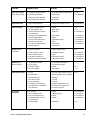
SYMPTOM
PROBABLE CAUSE
SOLUTION
REFERENCE
Engine does not start
(starter does not work)
•
•
•
•
•
•
•
•
• A-13
• Kubota Manual*
Engine will not stop
• Starter solenoid jammed
• Replace start solenoid or starter
• Kubota Manual*
Engine runs rough
• Fuel filters clogged or dirty
• Air filter plugged or dirty
• Fuel leak due to loose injection
pipe retaining nut
• Injection nozzle clogged/defective
• Injection pump defective
• Uneven cylinder compression
• Incorrect valve clearance
• Fuel return line clogged/kinked
• Governor defective
• Replace
• Clean/replace
• Tighten nut
• A-8
• A-3
• Kubota Manual*
•
•
•
•
•
•
Clean/replace
Replace
Repair/replace engine
Adjust
Clean/replace
Repair/replace
•
•
•
•
•
Kubota Manual*
Kubota Manual*
Kubota Manual*
Kubota Manual*
Kubota Manual*
Smoking (white or
blue exhaust)
•
•
•
•
•
Excessive engine oil
Piston ring worn or stuck
Incorrect injector timing
Low cylinder compression
Coolant in combustion chamber
•
•
•
•
•
Reduce to specified level
Repair/replace engine
Repair
Repair/replace engine
Repair/replace engine
•
•
•
•
•
A-2
Kubota Manual*
Kubota Manual*
Kubota Manual*
Kubota Manual*
Smoking (black or
dark gray exhaust)
•
•
•
•
Overloaded power draw
Low fuel grade
Fuel filters clogged
Air cleaner clogged
•
•
•
•
Reduce power consumption
Use specified fuel grade
Replace
Clean/replace
• A-3
• A-3
Unable to bleed coolant
•
•
•
•
•
•
•
Air lock
No coolant flow
Kinked coolant lines
Shut-off valves 'OFF'
Incorrect plumbing
Small fittings on truck engine
Low coolant level – Stand-Alone
APU model only
•
•
•
•
•
•
•
Run Truck engine until 85°C (185°F)
Check for blockages using flow indicator
Straighten
Turn 'ON'
Re-plumb
Change to larger fittings (3/4")
Fill coolant to the proper level at
the coolant surge tank
• A-9
Excessive oil
consumption
•
•
•
•
•
•
•
•
Replace
Replace the piston
Replace
Replace
•
•
•
•
Low battery voltage to the APU
Starter/solenoid defective
Poor positive cable connection
Poor ground cable connection
Oil ring worn
Piston ring groove worn
Valve stem and guide worn
Crankshaft bearing and crank
pin bearing worn
• Air filter clogged
Check battery cables/charge battery
Repair/replace
Check/repair
Check/repair
• Replace filter
Kubota Manual*
Kubota Manual*
Kubota Manual*
Kubota Manual*
• A-3
*Kubota Workshop Manual 97897-02400
62-11175 COMFORTPRO SERVICE MANUAL
3-3
SYMPTOM
PROBABLE CAUSE
SOLUTION
REFERENCE
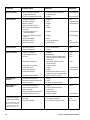
Oil level increases
• Diesel fuel getting to oil pan
through governor lever
• Fuel lift pump diaphragm defective
• Replace O-ring in lower portion
of governor lever
• Replace
• Kubota Manual*
•
•
•
•
•
•
•
•
•
•
• A-2
• Kubota Manual*
• Kubota Manual*
Low oil pressure
•
•
•
•
•
Engine oil insufficient
Oil strainer clogged
Oil filter clogged
Relief valve stuck with dirt
Relief valve spring weakened
or broken
Excessive oil clearance of
crankshaft bearings
Excessive oil clearance of rocker
arm boss
Oil passage clogged
Different type of oil
Oil pump defective
Replenish
Clean
Replace
Clean
Replace
• Kubota Manual*
• Replace
• Kubota Manual*
• Replace
• Kubota Manual*
• Clean
• Use the specified type
• Repair/replace
• A-2
• Kubota Manual*
High oil pressure
• Different type of oil
• Relief valve defective
• Use the specified type
• Replace
• A-2
Engine overheated
• Engine oil insufficient
• Fan belt broken or loose
• Air lock
• A-2
• A-2
• A-9
• Plugged or blocked radiator
• Replenish
• Repair/replace
• Check for air lock in Kubota engine
and ensure there is coolant, purge
if necessary
• Add coolant, purge if necessary
Inspect for leaks
• Repair Plumbing
• Replace
• Replace
• Check electrical controls, fan relay,
temperature sensor, wiring harnesses
• Clean or replace as required
Overcharging of
batteries
• Alternator malfunctioning
• Poor positive/ground connections
• Batteries defective
• Replace
• Repair
• Load test or replace batteries
• A-13
Dead batteries or
undercharge
•
•
•
•
•
•
•
•
•
•
• A-13
• Coolant level insufficient
•
•
•
•
APU suddenly stops
("Check APU" message
on Driver Control Panel
Coolant flow is restricted
Thermostat stuck
Water pump defective
Cooling fan defective
Alternator malfunctioning
Poor alternator connection
DC load too high
Poor positive/ground connections
Alternator belt loose/worn
• Low oil pressure
• Overheat
• Alternator Feedback
Replace
Check alternator connection
Reduce load
Check connections
Replace or tighten
• See "Low oil pressure"
• See "Engine overheated"
• See "Alternator Troubleshooting"
• A-9
• Kubota Manual*
• Kubota Manual*
• Kubota Manual*
• A-6
• A-6
• 3-15, A-13
Do not turn the Driver Control
Panel off. Go to the APU and
look at the APU Control Unit
lights for the correct code.
*Kubota Workshop Manual 97897-02400
3-4
62-11175 COMFORTPRO SERVICE MANUAL
SYMPTOM
PROBABLE CAUSE
SOLUTION
APU suddenly stops
• No fuel
(no message on Driver
Control Panel display)
• Air in the fuel system
• Water in fuel system
• Check fuel stand pipe length/fuel level
in tank
• Bleed air
• Drain fuel tank(s) and replace
fuel filters
• Check APU control cable, and
Driver Control Panel cable for shorts
or opens/replace
• Replace
• Tighten/replace
• Repair/replace
• Check battery cables/charge battery
• Faulty communication between the
APU Control Unit, CCU Control
Board and/or the Driver Control Panel
• Fuel solenoid faulty
• Alternator belt loose or broken
• Alternator faulty
• Low battery voltage
APU stops 15 seconds
• Low oil pressure
after starting sequence
• Overheat
completes ("Check APU"
message on Driver Control
Panel display)
REFERENCE
• A-8
• A-8
• A-3, A-8
• 3-16
• Kubota Manual*
• 3-15
• See "Low oil pressure"
• See "Engine overheated"
• 3- 4
• 3- 4
• Alternator belt loose or broken
• Alternator Defective
• Poor connection between alternator
and APU controller (brown wire)
• Tighten/replace
• Repair/replace
• Check connection / wire for breaks
• A-2
• 3-15
No "GLOWING" message
on the Driver Control
Panel, but APU will start
and run normally
• Faulty communication between the
APU Control Unit, CCU Control
Board and/or the Driver Control Panel
• Check APU control cable, and
Driver Control Panel cable for shorts
or opens/replace
No "GLOWING" message
on the Driver Control
Panel and APU will only
run with ON button
depressed
• Faulty communication between the
APU Control Unit, CCU Control
Board and/or the Driver Control Panel
• Check APU control cable, and
Driver Control Panel cable for shorts
or opens/replace
APU only ‘clicks’ after
glowing has finished
and is attempting to start
(ALT POWER light not on,
ALT F/B light does not
come on during glowing)
• Faulty APU Controller
• Replace APU Controller
APU only ‘clicks’ after
glowing has finished
and is attempting to start
(ALT F/B light on,
APU controller does not
come on during glowing)
• Loose connection from APU controller
to alternator, either at the APU
controller end or at the Alternator end
• Faulty Alternator
• Faulty APU Harness
• Troubleshoot the Alternator
This will occur when the APU
Control Unit sees a problem
during or after startup
APU stops after start
sequence completes.
APU will only run with
start button depressed
(no message on Driver
Control Panel display)
This will occur when the APU
Control Unit does not see the
Alternator feed back signal
during or after start up.
• 3-15
*Kubota Workshop Manual 97897-02400
62-11175 COMFORTPRO SERVICE MANUAL
3-5
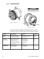
3.2 GENERATOR
WARNING
Disconnect the batteries from the
APU before performing any repairs.
Stand-Alone APU Generator
Integrated APU Generator
Each symptom is followed by a probable cause and suggested solution. To isolate the
possible cause, proceed in a systematic manner to determine the faulty component. This
guide does not cover all possible situations that may occur under all conditions of operation.
SYMPTOM
PROBABLE CAUSE
SOLUTION
REFERENCE
No voltage
• 35 Amp Breaker tripped
• Generator Belt loose/broken
• Determine reason and reset
• Tighten/replace
• A-5
• A-2
Low voltage
(below 100 Volts)
•
•
•
•
•
•
•
•
•
•
• A-2
• A-3
• A-3
Very low voltage
(4-10 Volts AC)
3-6
Generator belt loose/broken
Engine air filter dirty
Engine fuel system problem
Engine exhaust system problem
Engine speed low
• Wiring to capacitor
• Capacitor defective
Tighten/replace
Clean/replace filter
Change fuel filters
Clean/replace
Adjust
• Repair/replace
• Test and replace
• 3- 13
• 3- 13, 3- 14
62-11175 COMFORTPRO SERVICE MANUAL
3.3 DRIVER CONTROL PANEL
WARNING
Disconnect the batteries from the
APU before performing any repairs.
Each symptom is followed by a probable cause and suggested solution. To isolate the
possible cause, proceed in a systematic manner to determine the faulty component. This
guide does not cover all possible situations that may occur under all conditions of operation.
SYMPTOM
PROBABLE CAUSE
SOLUTION
REFERENCE
APU starts and runs,
but no CCU functions
work and "OUTLET
OFF" is displayed
• No 120 Volt power to CCU Board
• Controls "locked up"
• See "Generator" section
• Re-boot by turning APU off and
disconnecting battery power to
APU for 30 seconds
• 3- 6
A/C will not turn on
(no icon)
• Temperature in sleeper is too cold
• Temperature must be above 18.5°C
(65°F) (turn heat on to raise the
sleeper temp)
• Set temperature to lower setting
• 1- 6, 1- 9
• Temperature must be below 29.5°C
(85°F) (turn A/C on to lower the
sleeper temp)
• Set temperature to higher point
• 1- 6, 1- 9
• 1- 6, 1- 9
• Determine reason and press reset on
the Driver Control Panel
• Tighten/replace
• A-2
• Temperature is below Driver Control
Panel set point
Heat will not turn on
(no icon)
• Temperature in sleeper is too hot
• Temperature is above Driver Control
Panel set point
"HVAC BREAKER
RESET" is displayed
• 20 Amp CCU breaker tripped
• Generator belt loose
"TRIP W/LIGHTENING
BOLT ICON" is displayed
"LOW VOLTAGE"
is displayed
• 20 Amp outlet breaker tripped
• Generator belt loose
• Determine reason and press reset on
the Driver Control Panel
• Tighten/replace
•
•
•
•
•
•
•
•
•
•
•
•
Generator 35 Amp breaker tripped
Generator belt loose/broken
Engine air filter dirty
Engine fuel system problem
Engine exhaust system problem
Engine speed low
62-11175 COMFORTPRO SERVICE MANUAL
Determine reason and reset
Tighten/replace
Clean/replace filter
Change fuel filters
Clean/replace
Adjust
• 1- 6, 1- 9
•
•
•
•
3-6, A-5
3-6
A-3
A-3
• A-2
3-7
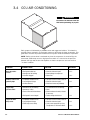
3.4 CCU AIR CONDITIONING
WARNING
Disconnect the batteries from the
APU before performing any repairs.
Each symptom is followed by a probable cause and suggested solution. To isolate the
possible cause, proceed in a systematic manner to determine the faulty component. This
guide does not cover all possible situations that may occur under all conditions of operation.
NOTE: The five minute timer is activated any time the compressor is turned off (by the
thermostat, EVAP temp sensor or high pressure switch. It is used to let the pressure
between the high and the low side equalize so that the compressor can start under a
"no load" condition.
SYMPTOM
PROBABLE CAUSE
SOLUTION
REFERENCE
Does not produce
cold air
• Refrigerant leaked out
• Compressor not working
• Inlet filter clogged
• Check for leaks and repair
• Check voltage at compressor
• Clean filter
• 2-3
Produces cold air and
gradually stops
• Evaporator blocked with ice
• Low refrigerant charge
• Air Duct blocked
• Increase air flow, increase return air
• Check for leaks and repair
• Check and remove any blockage
Tripped high
pressure switch
• Condenser fan not working
• Condenser is dirty
• Poor air flow around condenser
• See "Condenser fan not working"
• Clean
• Check condenser location, relocate
if necessary
• Reduce charge to 64–68 oz
• Refrigerant is over charged
Tripped on EVAP
temp sensor
3-8
• Evaporator blocked with ice
• Low refrigerant charge
• EVAP temp sensor faulty
• Increase air flow, increase return air
• Check for leaks and repair
• Verify sensor operation by using
Temperature vs. Resistance Chart
• A-3
• 2-1
• 3-9
• 2-1
• 2-1
• 2-3
62-11175 COMFORTPRO SERVICE MANUAL
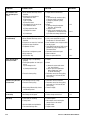
SYMPTOM
PROBABLE CAUSE
SOLUTION
REFERENCE
Condenser fan not
working
•
•
•
•
•
•
•
•
• 1- 6, 1- 9
• A-4
Compressor will not
start (no hum)
• High pressure switch open
• Evaporator frozen
A/C is not on
DC power fuse blown
Wiring damaged
Fan defective (seized)
• Five minute timer active
• Overload protector tripped
• Driver Control Panel not calling for A/C
• Compressor seized
Compressor will not
start (hums)
• Low A/C Voltage to CCU
• Starting capacitor defective
• Potential relay is open
• Compressor motor winding open
or shorted
• Internal mechanical trouble
in compressor
Compressor will not
start (hums but trips
on overload protection)
• Low A/C Voltage to unit
• Potential relay is failing to open
• Run capacitor is defective
• Excessively high discharge pressure
• Compressor motor has a winding
open or shorted
• Internal mechanical trouble in
compressor (tight)
Compressor starts and
runs, but short cycles
on overload protector
•
•
•
•
Low voltage to unit
Overload protector defective
Run capacitor is defective
Excessively high discharge pressure
• Compressor too hot – suction
line hot
• Compressor motor has a
winding shorted
Air conditioner runs
OK, but short cycles
• Overload protector
• Driver Control Panel too close
to ducts
62-11175 COMFORTPRO SERVICE MANUAL
Set temperature to lower setting
Determine reason and replace fuse
Repair/replace
Replace
• See "Tripped high pressure switch"
• See "Produces cold air and
gradually stops"
• Wait five full minutes
• Let unit cool down, check for
low refrigerant
• Set temperature to lower setting
• Replace compressor
• See "Generator" section
• Determine reason and replace
• Determine reason and correct,
replace if necessary
• Replace compressor
• 3- 8
• 3- 8
• 2- 1
• 3- 6
• Replace compressor
• See "Generator" section
• Determine reason and correct,
replace if necessary
• Determine reason and replace
• Check high pressure switch, possible
overcharge or insufficient cooling on
condenser (fan)
• Replace compressor
• 3- 6
• Replace compressor
•
•
•
•
See "Generator" section
Check current and replace protector
Determine reason and replace
Check condenser (fan) and for
restriction in refrigeration lines
• Check refrigerant charge (check for
leaks) and add if necessary
• Replace compressor
• See "Compressor starts and runs, but
short cycles on overload protector"
• Remount away from ducts
• 3- 6
• 2- 1
• 3- 9
• 1- 1
3-9
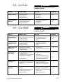
SYMPTOM
PROBABLE CAUSE
SOLUTION
Air conditioner runs
OK, but short cycles
(cont.)
• Driver Control Panel temp sensor
defective
• High pressure cut out due to:
a) Insufficient air flow
b) Overcharge
c) Air in system
d) Defective switch
• Low temp(de-ice) cut out due to:
a) Insufficient air flow
• Replace Driver Control Panel
b) Faulty expansion valve
c) Faulty de-ice sensor
d) Undercharge
A/C operates long
or continuously
• Shortage of refrigerant
• Driver Control Panel temp sensor
defective
• Sleeper has an excessive heat load
• Sleeper has poor insulation
• Evaporator coil iced
• Restriction in refrigerant system
• Dirty condenser
• CCU air filter dirty
Start capacitor open,
shorted, or blown
• Potential relay is not operating
properly
• Prolonged operation on start cycle
due to:
a) Low voltage to unit
b) Starting load too high
• Excessive short cycling
Potential relay defective
or burned out
• Line voltage to low or to high
• Excessive short cycling
• Relay being influenced by a loose
and vibrating mount
REFERENCE
• Check:
a) Air flow through condenser (fan)
b) Reduce charge to 64–68 oz.
c) Purge air (vacuum system)
d) Replace
• Check:
a) Air flow through evaporator
(fan, filter, vents closed)
b) Replace valve
c) Verify sensor operation by using
Temperature vs. Resistance Chart
d) Fix leak and recharge (64–68 oz)
• Fix leak and recharge (64–68 oz)
• Verify sensor operation by using
Temperature vs. Resistance Chart
• Cover windows, close sleeper curtains
• Insulate sleeper
• Faulty EVAP temp sensor, Verify sensor
operation by using Temperature vs.
Resistance Chart
• Determine location and repair
• Clean condenser
• Clean or replace CCU filter
• 2-1
• 2-1
• A-3
• Check:
a) Determine reason and correct
(see "Low Voltage")
b) Check: pressure equalization
before compressor starts,
(5 minute timer faulty)
• Determine reason for short cycling
and repair (see "Unit runs OK, but
short cycles")
• Determine reason and correct
• Determine reason for short cycling
and repair (see "Unit runs OK, but
short cycles")
• Remount rigidly
• Evaporator fan not running
• Overcharge of refrigerant
• Determine reason and correct
• Reduce charge to 64–68 oz.
Unit noisy
• Loose parts or mounting
• Tubing rattle
• Find and tighten
• Move object that is touching the
tubing to be free of contact
• Replace blade
• Replace motor
3-10
• A-11
• Replace
Suction line frosted
or sweating
• Bent fan blade causing vibration
• Fan motor bearings worn
• 2-1
• 3-11
• 2-1
62-11175 COMFORTPRO SERVICE MANUAL
3.5 CCU FAN
WARNING
Disconnect the batteries from the APU before
performing any repairs.
SYMPTOM
PROBABLE CAUSE
SOLUTION
REFERENCE
CCU fan not working
• Fuse on CCU Board
• Wiring defective
• Capacitor defective
• Check/replace
• Repair/replace
• Test/replace
• A-4
CCU fan only works on
high speed
• Low speed resistor defective
• Resistor wiring defective
• CCU Board defective
• Check/replace heating element
• Repair/replace
• Test/replace
• A-2
• A-2
3.6 CCU HEAT
WARNING
Disconnect the batteries from the APU before
performing any repairs.
SYMPTOM
PROBABLE CAUSE
SOLUTION
High Heat Mode does
not produce warm air
• Heat is not on (heat icon must be on) • Turn temperature setting up
• Thermo fuse blown
• Check/replace thermal fuse
• CCU Board defective
• Replace
• 1- 6, 1- 9
• A-2
Low Heat Mode does
not produce warm air
• Heat is not on (heat icon must be on) • Turn temperature setting up
• Thermo fuse blown
• Check/replace thermal fuse
• CCU Board defective
• Replace
• 1- 6, 1- 9
• A-2
Produces warm air and
gradually stops
• Set point has been reached
• High temperature cut out due to
insufficient air flow
• Turn set point up
• Increase air flow/Increase return air
• 1- 6, 1- 9
High temperature
sensor tripping
• High temperature cut out due to
insufficient air flow
• Temperature sensor wiring damaged
• Temperature sensor defective
• Increase air flow, increase return air
• Ducting blocked
• Repair/replace
• Verify sensor operation by using
Temperature vs. Resistance Chart
• Check and remove any blockage
Heat works OK, but
short cycles
• Driver Control Panel too close to duct
• Driver Control Panel temp sensor
defective
• Remount away from ducts
• Verify sensor operation by using
Temperature vs. Resistance Chart
Heat operates long or
continuously
• Driver Control Panel temp sensor
defective
• Sleeper has an excessive heat loss
• Sleeper has poor insulation
• CCU air filter dirty
• Verify sensor operation by using
Temperature vs. Resistance Chart
• Cover windows, close sleeper curtains
• Insulate sleeper
• Clean/replace CCU filter
62-11175 COMFORTPRO SERVICE MANUAL
REFERENCE
• A-11
• 1- 1
• A-11
• A-3
3-11
3.7 RECEPTACLE PANEL
WARNING
Disconnect the batteries from the
APU before performing any repairs.
Each symptom is followed by a probable cause and suggested solution. To isolate the
possible cause, proceed in a systematic manner to determine the faulty component. This
guide does not cover all possible situations that may occur under all conditions of operation.
SYMPTOM
PROBABLE CAUSE
SOLUTION
REFERENCE
No 120 VAC power
• High Heat Mode is selected
• APU not running
• 35 Amp breaker tripped at
generator
• Switch to 'Low Heat' position
• Start APU
• See "Generator" Section
• 1- 6, 1- 9
• 1- 6, 1- 9
• 3-6
3-12
62-11175 COMFORTPRO SERVICE MANUAL
3.8 TESTING PROCEDURES
3.8.1 Testing AMP draw for components
When checking functions of individual components, place amp clamp over black (power)
wire coming in from the generator to the CCU board. (As shown in below.)
When cross-referenced with the “AMP DRAW AND VOLTAGE CHART”, the components
should show the same amp readings.
3.8.2 Testing Voltage and Hz readings:
When checking for 120 VAC at the CCU board, the probes are placed at the black wire
terminal and the white wire terminal.
When APU is running there should always be between 110 – 130 VAC present.
When APU is running the Hz reading should always be 60 +/- 2.
62-11175 COMFORTPRO SERVICE MANUAL
3-13
3.9 ADDITIONAL INFORMATION
3.9.1 Adjusting the 120 AC Voltage
This does not need to be adjusted under normal operation. If you find low
AC voltage, check the generator belt, air filter, fuel filters and exhaust
system before adjusting.
1
With the APU running turn all 120-volt components off.
2
Measuring the voltage at the outlet panel adjust the engine speed
until 120 (+/- 10) volts AC and 60 Hz +/- 2 Hz is read.
3.9.2 Capacitor Troubleshooting
1
Disconnect generator output from breaker.
2
With APU running, measure generator output voltage.
3
If voltage < 105 volts AC, try a known good capacitor and retest.
NOTE: Most multimeters will not test this capacitor reliably in either MF
(capacitance) or Ω (resistance) modes. The above methods are the ONLY
reliable means of testing the capacitor without a lab-grade capacitance meter.
3.9.3 Capacitor Theory
A single-phase motor can not be "fed" with just single-phase current
(120 Volt AC), there must be some way to create an artificial second
(or third) phase to smooth out the magnetic filed. Capacitors are electrical
components that help create and strengthen the artificial second phase in
single-phase electric motors. They work much like a battery, storing and
releasing a charge of electricity (AC Voltage) that is out of phase with the
oscillating (AC) current that is fed into the motor.
If single-phase induction motors do not have a second phase (created by
the capacitor) then it will not have an even magnetic field. This will cause
the rotor to hesitate at those spots that are uneven. This hesitation will
cause the rotor to spin slowly or even stop moving (compounding the
problem), draw more current (Amp's), become noisy, and overheat.
The CCU Fan and the Compressor use a Run Capacitor. Run Capacitors
are designed for continuous duty, and are energized the entire time the
motor is running.
The Compressor motor needs a Start Capacitor in addition to the Run
Capacitor. Start Capacitors are designed for momentary use. Start
capacitors stay energized long enough to bring the motor to75% of full
speed (RPM) and are then taken out of the circuit by means of a
Potential Relay.
3-14
62-11175 COMFORTPRO SERVICE MANUAL
3.9.4 Potential Relay Theory
In a Capacitor Start, Capacitor Run compressor the start capacitor is only designed for
momentary use. The Potential Relay (NC) is used to connect and disconnect the start
capacitor from the compressors start windings. Induced Voltage is generated in the start
winding when of the compressor when it is running. The voltage induced in to the start
winding is a function of the speed of the rotor and the magnetic field that is generated.
When the compressor is first energized, the voltage in the start windings is less than the
line voltage (120 VAC). As the compressor speed (RPM) increases, the voltage in the
start windings increases significantly higher than the line voltage (up to 275 Volts) until
full compressor speed (RPM) is reached.
The Potential Relay's coil is connected across the start windings, and is designed to
respond to the increase of voltage as the compressor's speed increases. The normally
closed Potential relay contacts are designed to open at a 75% of the full compressor
speed (RPM). The Start Capacitor is connected to the relay contacts so when the relay
opens (75% of the full compressor speed RPM) the start capacitor is disconnected from
the system.
3.9.5 Alternator Troubleshooting
1 Unit switched OFF, harness connected
Check alternator feedback wire (brown) at the alternator for 5 volts.
If 5 volts are not found disconnect 'T' connector from alternator and retest. If 5 volts are
found the alternator is faulty.
If 0 volt is found check alternator feedback wire (brown) for open, and power (B+) and ground
(B-) to APU controller and repair as required. If no fault is found the APU controller is faulty.
2 Unit switched ON (glowing), harness connected
Check alternator field power wire (purple) for 12 volts. If 0 volt is found check alternator
field power wire (purple) for open and power (B+) and ground (B-) to APU controller and
repair as required. If no fault found the APU controller is faulty.
Check alternator feedback wire (brown) at alternator for 0 volt. If 5 volts are found the
alternator is faulty.
3 Unit running, harness connected
Check alternator feedback wire (brown) at alternator for 5 volt. If 0 volts are found the
alternator is faulty.
4 Unit running, then stops
Check alternator jumper harness (red) at alternator connection for 12.5-14.1 volts.
If 16-17 volts is found, check for alternator jumper (red) open and replace as required.
62-11175 COMFORTPRO SERVICE MANUAL
3-15
3.9.6 Fuel Solenoid Troubleshooting
If a faulty fuel solenoid is suspected (per diagnostic flow chart 62-11409) then use
instructions below for troubleshooting.
Unplug the solenoid connector and check the resistance between the following terminals
with a DVOM.
• White to Black = 0.3 – 0.7 Ohm
• Red to Black = 13 – 25 Ohm
• White to Red = Open (OL)
If the resistance is out of range then replace the fuel solenoid.
If the resistance measured is within range then check the fuel solenoid circuit in the APU
controller for open or close.
If resistance is within range and there are no opens or shorts in the circuit in the APU
controller, then replace the APU controller.
3-16
62-11175 COMFORTPRO SERVICE MANUAL
APPENDICES
CAPACITIES AND SPECIFICATIONS .................................................... A-1
FUSE LOCATIONS ............................................................................ A-4
CIRCUIT BREAKER LOCATIONS.......................................................... A-5
APU CONTROL UNIT ......................................................................... A-6
CCU CONTROLLER ........................................................................... A-7
FUEL SYSTEM PURGE PROCEDURE ................................................... A-8
COOLANT PURGE PROCEDURE.......................................................... A-9
DEFROST/HEAT AND DCP SENSOR CHARTS .................................... A-11
ENGINE INTERLOCK DIAGRAMS ...................................................... A-12
APU WIRING DIAGRAMS ................................................................. A-13
CAPACITIES AND SPECIFICATIONS
APU
Engine . . . . . . . . . . . . . . 13.9 hp Kubota, 2 cyl, 479cc (model Z482-B)
Engine Oil . . . . . . . . . . . . 3.5 US Qts (3.3L) with filter.
You can use any API service CI-4, CJ-4, CF-4,
CG-4 or CH-4 oil and any ASE Viscosity (or weight)
of Oil according to the chart.
40
30
20
SINGLE
GRADE
20W
10W
5W
5W20
5W30
MULTI
GRADE
10W30
15W40
20W50
243
253
263
273
283
293
303
313
323 K
-30
-20
-10
0
10
20
30
40
50 ∞ C
-22
-4
14
32
50
68
86
104
122 ∞ F
AMBIENT
TEMP
Belt Tension . . . . . . . . . . Alternator 73 – 84 lbs (325 – 374 N).
Integrated APU Generator 100 – 112 lbs
(445 – 500 N).
62-11175 COMFORTPRO SERVICE MANUAL
A-1
Engine compression . . . .
Engine Speed . . . . . . . . .
Valve Clearance (Cold) . . .
Engine Drain Plug . . . . . .
Intake & Exhaust Valves .
Fast Burn Glow Plugs . . . .
Starter . . . . . . . . . . . . . .
Alternator . . . . . . . . . . . .
Generator . . . . . . . . . . . .
Fuel Solenoid . . . . . . . . .
327 PSI min. (2.26 MPa min).
Approx. 2400 RPM.
0.145 to 0.185 mm (0.0057 to 0.0073 in).
Torque 25 ± 2 ft/lb.
0.0057-0.0073" (0.145 – 0.185 mm) Cold.
0.9 Ohms each, 22 Amps then ramps down
to 12 Amps.
160 Cranking Amps (includes glow plugs and
fuel solenoid).
60 Amps @ 14.2 Volts DC.
35 Amps @ 120 Volts AC.
Pull-in winding 29 Amps, Hold winding 1 Amp.
Comfort Pro APU Units with serial number prior to NXC 98206420:
Oil Pressure switch . . . . . Normally closed, open at 7 psi.
Overtemp switch . . . . . . . Normally open, closed at 245°F
Comfort Pro APU Units with serial number NXC 98206420 and later:
Oil Pressure switch . . . . . Normally open, closed at 7 psi.
Overtemp switch . . . . . . . Normally closed, open at 110°C (230°F)
Thermostat . . . . . . . . . . . Starts to open at 71°C (160°F) and fully opens
at 85°C (185°F).
CCU
Air Conditioner . . . . . . . 12,000 BTU/ hr hermetic compressor.
System capacity . . . . 50–55 oz of R-134A.
System Oil capacity . . 14 oz of PVE (Polyvinylether).
Compressor . . . . . . . 6–10 Amps @ 120 Volts.
Condenser Fan . . . . . 9-12 Amps .
Binary Pressure Switch . Normally closed between 26–335 psi.
Operating pressures . . Low side, 24–45 psi, High side, 110–250 psi.
Condenser Air inlet to outlet temperature difference should be no more
than -1°C (30°F). Evaporator Air inlet to outlet temperature difference
-8° to -4°C (18° to 25°F).
Heat
High . . . . . . . . . . . . . . 10,000 BTU/hr (3,000 watts).
Low . . . . . . . . . . . . . . 5,000 BTU/hr (1,500 watts).
Blower Fan low speed
resister . . . . . . . . . . . 25 Ohms.
Heating Coils . . . . . . . 10 Ohms each.
Thermo Fuse . . . . . . . Blows at 152°C (307.4°F ).
A-2
62-11175 COMFORTPRO SERVICE MANUAL
Maintenance Parts
OIL FILTER
INLINE FUEL FILTER
OIL DIPSTICK
FUEL FILTER
AIR FILTER
AIR INLET FILTER
Figure A-1: Maintenance Components, CCU and Integrated APU.
DC POWER FUSE
12V, 20 AMP
BREAKER PANEL — 35A MAIN BREAKER,
15A ENGINE OIL/BLOCK HEATER
BREAKER
IN-LINE FUEL FILTER
ALTERNATOR BELT
OIL DIPSTICK
RADIATOR WITH
ELECTRIC FAN
APU
CONTROLLER
APU ENCLOSURE BOLTS (8)
AIR FILTER
OIL
FILTER
CAPACITOR LOCATED BEHIND GENERATOR
OIL
DRAIN
PLUG
FUEL FILTER
GENERATOR BELT
Figure A-2: Maintenance Components, Stand-Alone APU.
62-11175 COMFORTPRO SERVICE MANUAL
A-3
FUSE LOCATIONS
APU
DC POWER FUSE
12V, 20 AMP
CCU FAN FUSE
250V, 3 AMP
THERMAL FUSE x2
CCU
Figure A-3: Fuse Locations
A-4
62-11175 COMFORTPRO SERVICE MANUAL
CIRCUIT BREAKER LOCATIONS
GENERATOR
35 AMP BREAKER
(MANUAL RESET)
CCU BREAKER OUTLET BREAKER
(AUTO RESET) (AUTO RESET)
CCU
Figure A-4: Circuit Breaker Locations
62-11175 COMFORTPRO SERVICE MANUAL
A-5
APU CONTROL UNIT
Output Indicators
APU
CONTROL
UNIT
STARTER – This is the output (+) to the Starter solenoid.
GLOW PLUGS – This is the output (+) to the Glow Plugs.
STARTER
SOL PULL – This is the output (+) to the Fuel Solenoid Pull windings
(Only on during cranking for the first .5 seconds).
GLOW PLUGS
SOL PULL
SOL HOLD – This is the output (+) to the Fuel Solenoid Hold windings.
SOL HOLD
ALT POWER
ALT POWER – This is the output (+) to the Alternator field windings.
COOLANT
OIL
TEMP
ALT F/B
Input Indicators
COOLANT – Not Used.
OIL – This is the input (-) from the Oil Pressure Switch. You will see this
light illuminated when the oil pressure is below 7 psi. This will shut the
APU off when it is illuminated.
TEMP – This is the input (-) from the Overheat Switch. You will see this
light illuminated when the coolant temperature is above the ‘Over
Temperature Limit’. This will shut the APU off when it is illuminated.
Figure A-5: APU Control Unit
ALT F/B – This is the input (-) from the Alternator Charging light. When
the APU is not running this light will be on. When the APU is running and
the Alternator is charging this light will be out (or very dim). This will shut
the APU off when the light is illuminated.
Oil Pressure & Coolant Temperature Switch Operation
ComfortPro APU Units serial number NXC 98206420 and later:
OIL PRESSURE SWITCH (NO) – Closed > 7 psi
COOLANT TEMPERATURE SWITCH (NC) – Open > 110°C (230°F)
ComfortPro APU Units serial number prior to NXC 98206420:
OIL PRESSURE SWITCH (NC) – Open > 7 psi
COOLANT TEMPERATURE SWITCH (NO) – Closed > 118.5°C (245°F)
A-6
62-11175 COMFORTPRO SERVICE MANUAL
CCU CONTROLLER
Inputs
AC – This is the input from the Driver Control Panel only when it is calling
for Air conditioning. (Low or High A/C.)
HEAT – This is the input from the Driver Control Panel only when it is
calling for Heat. (Low or High Heat.)
FAN LOW – This is the input from the Driver Control Panel only when it is
calling for CCU Low Fan. (Used in Fan, A/C, and Heat modes.)
FAN HIGH – This is the input from the Driver Control Panel only when it is
calling for CCU High Fan. (Used in Fan, A/C, and Heat modes.)
*Outputs
OUTLET – This is the output signal to the Power Outlet relay. It is On any
time 120 VAC Power is available to the Outlet. If High Heat mode is selected
the Outlet will be turned off.
LOW HEAT – This is the output signal to the Low Heat relay. It is On any
time Low Heat is called for.
**COMPRESSOR – This is the output signal to the A/C Compressor relay.
It is On any Time the A/C is called for. (Low or High.)
**CONDENSER – This is the output signal to the Condenser Fan relay. It is
On any Time the A/C is called for. (Low or High.)
LOW FAN – This is the Output signal to the CCU Low Fan relay. It is On any
time the CCU Low Fan is called for. (Used in Fan, A/C, and Heat mode.)
HIGH FAN – This is the Output signal to the CCU High Fan relay. It is On any
time the CCU High Fan is called for. (Used in Fan, A/C, and Heat modes.)
HIGH HEAT – This is the output signal to the High Heat relay. It is On any
time High Heat is called for. High Heat and Outlet can not be on at the
same time.
Service Light
NOTICE
If Service Light is illuminated, reprogram or replacement of CCU board may
be required.
Service Light will flash when CCU
is OFF.
*NOTE: Outputs only indicate the signal to turn the component relay on.
They do not indicate that the actual component itself is working.
**NOTE: Air Conditioning is a sequence start. CCU fan will come on first,
0.5 seconds later the Condenser Fan will come on, and 0.5 seconds after
the Condenser fan the A/C Compressor will come on.
62-11175 COMFORTPRO SERVICE MANUAL
A-7
FUEL SYSTEM PURGE
PROCEDURE
1. Start the APU with the APU Test Switch Module. If APU fails to start,
crank in 15 second bursts until fuel system is purged of air and APU
starts and runs smoothly.
OPEN TO BLEED THE
FUEL SYSTEM
FUEL FILTER
Figure A-6: Fuel Filter
A-8
62-11175 COMFORTPRO SERVICE MANUAL
COOLANT PURGE PROCEDURE
FOR INTEGRATED APU
1. Ensure that the coolant supply valve to the APU (located at the truck
engine) and the coolant return valve to the APU (also located at the
truck engine) are open.
2. Release pressure from coolant system.
3. Remove the truck engine radiator cap.
4. Top up the coolant if necessary in the expansion tank.
5. Run the truck engine at fast idle until 85°C (185°F) is reached on truck
temperature gauge. This should purge most of the air out of the APU.
6. Purging Air From the Coolant.
• Place thermostat drain hose into bucket (see Figure A-7).
• Open the thermostat bleed valve, using a wrench, and let any trapped
air escape until a steady stream of coolant flows from the valve.
• Close thermostat bleeder fitting.
• Top up the coolant if necessary in the truck expansion tank.
• Run the truck engine at fast idle for another 10 minutes to continue
purging air.
THERMOSTAT
DRAIN HOSE
BLEEDER VALVE
OPEN 1/4–1/2 CCW
1/2"
WRENCH
Figure A-7: Drain Hook-up
62-11175 COMFORTPRO SERVICE MANUAL
A-9
7. Start the APU by following the instructions on page 1-7 (Multi-Function
Driver Control Panel).
8. With the APU and truck engines running, open the thermostat bleed
valve and let any trapped air escape until a steady stream of coolant
flows from the valve.
9. Shut the truck engine off.
10. Check the truck engine; ensure it is getting hot coolant from the APU.
If it is not, the APU is not purged of all its air. Stop APU by following
the instructions on page 1-7 (Multi-Function Driver Control Panel).
Check for a restriction (i.e. valves/kinks etc.) and repeat steps 5 to 9.
11. Let APU run for at least 30 minutes. During this time keep checking
for signs of coolant leaks, fuel leaks and overheating.
12. Top up the coolant if necessary in the truck expansion tank and
replace the truck engine radiator cap.
13. Clean up any spilled coolant from inside APU and on the ground.
COOLANT FILL PROCEDURE
FOR STAND-ALONE APU
1. With the surge tank mounted, remove the pressure cap.
2. Slowly fill the cooling system with the recommended coolant until the
coolant level is mid level at the surge tank sight glass.
3. Start the APU engine and open the bleeder valve at the thermostat
housing to allow air to escape.
4. Allow the engine to warm up to operating temperature while
maintaining the proper coolant level in the surge tank.
5. Install the surge tank pressure cap and allow the engine to run.
Check for leaks.
System Air Bleed
WARNING
Do not operate the engine without
the enclosure cover in place.
Failure to do so may result in injury.
1. Run the APU engine until 76.6°C (170°F ) is reached.
2. Open the thermostat bleed valve, as shown, and let trapped air
escape until a steady stream of coolant flows from the valve.
3. Close the thermostat bleeder fitting.
4. Top up the coolant in the surge tank if necessary and replace the
surge tank pressure cap.
5. Clean up any spilled coolant from inside APU and on the ground.
A-10
62-11175 COMFORTPRO SERVICE MANUAL
DEFROST/HEAT & DCP SENSOR
Temperature vs.
Resistance Chart
62-11175 COMFORTPRO SERVICE MANUAL
RESISTANCE Ω
T(°C)
T(°F)
15
59
157.6
(kΩ)
16
61
150.4
(kΩ)
17
63
143.5
(kΩ)
18
64
137.1
(kΩ)
19
66
130.9
(kΩ)
20
68
125.1
(kΩ)
21
70
119.6
(kΩ)
22
72
114.3
(kΩ)
23
73
109.3
(kΩ)
24
75
104.5
(kΩ)
25
77
100.0
(kΩ)
26
79
95.7
(kΩ)
27
81
91.6
(kΩ)
28
82
87.7
(kΩ)
29
84
84.0
(kΩ)
30
86
80.5
(kΩ)
31
88
77.1
(kΩ)
32
90
73.9
(kΩ)
33
91
70.9
(kΩ)
34
93
68.0
(kΩ)
35
95
65.2
(kΩ)
36
97
62.5
(kΩ)
37
99
60.0
(kΩ)
38
100
57.6
(kΩ)
39
102
55.3
(kΩ)
40
104
53.1
(kΩ)
41
106
51.0
(kΩ)
42
108
49.0
(kΩ)
43
109
47.1
(kΩ)
44
111
45.3
(kΩ)
45
113
43.5
(kΩ)
46
115
41.9
(kΩ)
47
117
40.3
(kΩ)
48
118
38.7
(kΩ)
49
120
37.3
(kΩ)
50
122
35.9
(kΩ)
A-11
APU
CONTROL
RED
GRN
WHT
WHT
RED
PUR
BRN
ORG
BLU
RED
BLK
RED
RED
GRN
WHT
BLK
(-)
BLK
GLOW PLUG #1
GLOW PLUG #2
P
IG
L
A
B
A
B
DRIVER
CONTROL
PANEL
(DCP)
POWER (120 VAC)
GROUND
A
B
A
A
A
S
R
B
C
(+12 VDC)
134a A/C
COMPRESSOR
AC PRESSURE
B
SWITCH (NC)
OPEN@P<28 PSI & >325 PSI
GROUND(-)
COMM TO APU: GLOWRUN 2.5V / CRANKING 3.5V
COMM FROM CCU
COMM TO CCU
COMM TO CCU
COMM FROM APU: GLOW RUN 5V / FAULT 1.5V
INPUT (12 VDC +)
GROUND(-)
B
OUTLET (120 VAC)
CONDENSOR
TEMPERATURE
SWITCH (NO) - CLOSE > 245° F
OIL PRESSURE
SWITCH (NC) - OPEN > 7 PSI
ALTERNATOR
FUEL SOLENOID
INPUT, BATTERY(12VDC +)
COMM TO APU: GLOWPLUG RUN 2.5 VDC / CRANKING 3.5 VDC
COMM FROM APU: GLOW/RUN 5VDC / FAULT 1.5 VDC
INPUT, GROUND (-) BLACK
TEMP
SENSOR
VEHICLE SLEEPER
BRN
WHT/BRN
GRN
WHT/BLU
BLU
WHT/GRN
ORG
WHT/ORG
BLK
BLK
RED
GRN
WHT
BLK
BLK
WHT
BLK
RED
WHT
WHT
BLK
GRN
WHT
BLK
GRN
WHT
BLK
J4-8
J4-7
J4-6
J4-5
J4-4
J4-3
J4-2
J4-1
JP12-3
JP12-2
JP12-1
J3-3
J3-4
J3-2
J3-1
JP10-1
JP10-2
JP8-1
JP8-2
JP8-3
JP5-1
JP5-2
JP1-1
JP1-2
JP1-3
JP2-1
JP2-2
JP2-3
JP11-2
JP13-1
JP13-2
J2-1
J2-2
J2-3
J2-4
JP7-1
JP7-2
JP14-1
JP14-2
JP4-1
JP4-2
JP3-1
JP3-2
JP3-3
J1-1
J1-2
J1-3
J1-4
J1-5
RED
2
1
WHITE PLUG
EVAP SENSOR (5 VDC +)
GROUND (-)
BLK
BLK
HEATER SENSOR (5 VDC +)
GROUND (-)
THERMAL
FUSE
BLK
BLK
EVAPORATOR
HEATER FAN
BLK
BLU
BRN
GRN/YEL
CAPACITOR - COMPRESSOR START
(189-227UF) BLACK
CAPACITOR - COMPRESSOR RUN
(35UF) SILVER
T3
T7
T2
LOW HEAT
HIGH HEAT
HEAT UNIT
CAPACITOR - BLOWER RUN
(25UF) SILVER
T1
T5
T6
T8
30-864-50B
T9
INPUT (60 - 80 VAC)
GRN
GRN
YEL
YEL
WHT
WHT
POWER (120 VAC)
NEUTRAL
INPUT, RUN CAPACITOR
CHASSIS GROUND (NOT USED)
BLACK PLUG
BRN
BRN
BLK (120VAC)
WHT
RED (120 VAC)
WHT
THERMAL
FUSE
OUTPUT (120 VAC)
POTENTIAL
RELAY
BREAKER - OUTLET
OR HI-HEAT
AUTO RE-SET
5
CLIMATE CONTROL UNIT (CCU)
BLK
WHT
BREAKER - HVAC
AUTO RE-SET
JP11-1
CLIMATE CONTROL UNIT (CCU)
INTEGRATED APU WIRING DIAGRAM (30-864-50B)
APU Units serial number prior to NXC 98206420.
WARNING BUZZER
WHT
WHT
WHT
PULL
HOLD
ALT FIELD POWER
ALT FEEDBACK
ALT OUTPUT (+12 VDC)
FUSE
(20 AMP)
SOLENOID
BREAKER
35 AMP
CAPACITOR
APU STARTER
INTERNAL GRND
GENERATOR
NEUTRAL
VEHICLE SLEEPER
3 AMP
AUXILIARY POWER UNIT (APU)
J2-1
J2-2
J2-3
J2-4
J2-5
J2-6
J2-7
J2-8
J2-9
J2-10
J2-11
J2-12
J1-1
J1-2
J1-3
J1-4
RED
(+)
BLK
AUXILIARY POWER UNIT (APU)
BLOWER
FUSE
62-11175 COMFORTPRO SERVICE MANUAL
A-12
WHT
APU
CONTROL
RED
GRN
WHT
WHT
RED
PUR
BRN
ORG
BLU
RED
BLK
RED
RED
GRN
WHT
BLK
(-)
BLK
GLOW PLUG #1
GLOW PLUG #2
B
A
B
A
DRIVER
CONTROL
PANEL
(DCP)
B
A
B
A
C
(+12 VDC)
134a A/C
COMPRESSOR
S
R
AC PRESSURE
B
SWITCH (NC)
OPEN@P<28 PSI & >325 PSI
GROUND(-)
COMM TO APU: GLOWRUN 2.5V / CRANKING 3.5V
COMM FROM CCU
COMM TO CCU
COMM TO CCU
COMM FROM APU: GLOW RUN 5V / FAULT 1.5V
INPUT (12 VDC +)
GROUND(-)
VEHICLE SLEEPER
TEMP
SENSOR
POWER (120 VAC)
GROUND
OUTLET (120 VAC)
CONDENSOR
TEMPERATURE
SWITCH (NC) - OPEN > 230°F
OIL PRESSURE
SWITCH (NO) - CLOSED > 7 PSI
ALTERNATOR
FUEL SOLENOID
INPUT, BATTERY(12VDC +)
COMM TO APU: GLOWPLUG RUN 2.5 VDC / CRANKING 3.5 VDC
COMM FROM APU: GLOW/RUN 5VDC / FAULT 1.5 VDC
INPUT, GROUND (-) BLACK
P
IG
L
APU STARTER
CAPACITOR
BREAKER
35 AMP
A
B
A
BRN
WHT/BRN
GRN
WHT/BLU
BLU
WHT/GRN
ORG
WHT/ORG
BLK
BLK
RED
GRN
WHT
BLK
BLK
WHT
BLK
RED
WHT
WHT
BLK
GRN
WHT
BLK
GRN
WHT
BLK
J4-8
J4-7
J4-6
J4-5
J4-4
J4-3
J4-2
J4-1
JP12-3
JP12-2
JP12-1
J3-3
J3-4
J3-2
J3-1
JP10-1
JP10-2
JP8-1
JP8-2
JP8-3
JP5-1
JP5-2
JP1-1
JP1-2
JP1-3
JP2-1
JP2-2
JP2-3
JP11-2
JP13-1
JP13-2
J2-1
J2-2
J2-3
J2-4
JP7-1
JP7-2
JP14-1
JP14-2
JP4-1
JP4-2
JP3-1
JP3-2
JP3-3
J1-1
J1-2
J1-3
J1-4
J1-5
RED
2
1
WHITE PLUG
EVAP SENSOR (5 VDC +)
GROUND (-)
BLK
BLK
HEATER SENSOR (5 VDC +)
GROUND (-)
THERMAL
FUSE
BLK
BLK
EVAPORATOR
HEATER FAN
BLK
BLU
BRN
GRN/YEL
CAPACITOR - COMPRESSOR START
(189-227UF) BLACK
CAPACITOR - COMPRESSOR RUN
(35UF) SILVER
T3
T7
T2
30-864-50C
LOW HEAT
HIGH HEAT
HEAT UNIT
CAPACITOR - BLOWER RUN
(25UF) SILVER
T1
T5
T6
T8
T9
INPUT (60 - 80 VAC)
GRN
GRN
YEL
YEL
WHT
WHT
POWER (120 VAC)
NEUTRAL
INPUT, RUN CAPACITOR
CHASSIS GROUND (NOT USED)
BLACK PLUG
BRN
BRN
BLK (120VAC)
WHT
RED (120 VAC)
WHT
THERMAL
FUSE
OUTPUT (120 VAC)
POTENTIAL
RELAY
BREAKER - OUTLET
OR HI-HEAT
AUTO RE-SET
5
CLIMATE CONTROL UNIT (CCU)
BLK
WHT
BREAKER - HVAC
AUTO RE-SET
JP11-1
CLIMATE CONTROL UNIT (CCU)
INTEGRATED APU WIRING DIAGRAM (30-864-50C)
APU Units serial number NXC 98206420 and later.
WARNING BUZZER
WHT
WHT
WHT
PULL
HOLD
ALT FIELD POWER
ALT FEEDBACK
ALT OUTPUT (+12 VDC)
FUSE
(20 AMP)
SOLENOID
INTERNAL GRND
GENERATOR
NEUTRAL
VEHICLE SLEEPER
3 AMP
AUXILIARY POWER UNIT (APU)
J2-1
J2-2
J2-3
J2-4
J2-5
J2-6
J2-7
J2-8
J2-9
J2-10
J2-11
J2-12
J1-1
J1-2
J1-3
J1-4
RED
(+)
BLK
AUXILIARY POWER UNIT (APU)
BLOWER
FUSE
A-13
62-11175 COMFORTPRO SERVICE MANUAL
WHT
STARTER
GLOW PLUGS
SOL PULL
SOL HOLD
RED
GRN
WHT
WHT
RED
PUR
BRN
ORG
BLU
RED
BLK
RED
GLOW PLUG #1
CAPACITOR
P
IG
L
A
B
B
DRIVER
CONTROL
PANEL
(DCP)
B
CONDENSOR
POWER (120 VAC)
A
A
OUTLET (120 VAC)
B
A
A
S
R
B
C
(+12 VDC)
134a A/C
COMPRESSOR
AC PRESSURE
B
SWITCH (NC)
OPEN@P<28 PSI & >325 PSI
GROUND(-)
COMM TO APU: GLOWRUN 2.5V / CRANKING 3.5V
COMM FROM CCU
COMM TO CCU
COMM TO CCU
COMM FROM APU: GLOW RUN 5V / FAULT 1.5V
INPUT (12 VDC +)
GROUND(-)
VEHICLE SLEEPER
TEMP
SENSOR
FUEL SOLENOID
ALTERNATOR
OIL PRESSURE
SWITCH (NO) - CLOSED > 7 PSI
B
A
RAD FAN
TEMPERATURE
SWITCH (NC) - OPEN > 230° F
A
A
TMP SWITCH
BREAKER
35 AMP
B
INPUT, BATTERY(12VDC +)
COMM TO APU: GLOWPLUG RUN 2.5 VDC / CRANKING 3.5 VDC
COMM FROM APU: GLOW/RUN 5VDC / FAULT 1.5 VDC
INPUT, GROUND (-) BLACK
GLOW PLUG #2
BRN
WHT/BRN
GRN
WHT/BLU
BLU
WHT/GRN
ORG
WHT/ORG
BLK
BLK
RED
GRN
WHT
BLK
BLK
WHT
BLK
RED
WHT
WHT
BLK
GRN
WHT
BLK
GRN
WHT
BLK
J4-8
J4-7
J4-6
J4-5
J4-4
J4-3
J4-2
J4-1
JP12-3
JP12-2
JP12-1
J3-3
J3-4
J3-2
J3-1
JP10-1
JP10-2
JP8-1
JP8-2
JP8-3
JP5-1
JP5-2
JP1-1
JP1-2
JP1-3
JP11-2
JP13-1
JP13-2
J2-1
J2-2
J2-3
J2-4
JP7-1
JP7-2
JP14-1
JP14-2
JP4-1
JP4-2
JP3-1
JP3-2
JP3-3
J1-1
J1-2
J1-3
J1-4
J1-5
RED
2
1
WHITE PLUG
EVAP SENSOR (5 VDC +) BLK
BLK
GROUND (-)
HEATER SENSOR (5 VDC +)
GROUND (-)
BLACK PLUG
THERMAL
FUSE
BLK
BLK
EVAPORATOR
HEATER FAN
BLK
BLU
BRN
GRN/YEL
CAPACITOR - COMPRESSOR START
(189-227UF) BLACK
CAPACITOR - COMPRESSOR RUN
(35UF) SILVER
T3
T7
T2
LOW HEAT
HIGH HEAT
HEAT UNIT
CAPACITOR - BLOWER RUN
(25UF) SILVER
T1
T5
T6
T8
30-S64-01A
T9
INPUT (60 - 80 VAC)
GRN
GRN
YEL
YEL
WHT
WHT
POWER (120 VAC)
NEUTRAL
INPUT, RUN CAPACITOR
CHASSIS GROUND (NOT USED)
BRN
BRN
BLK (120VAC)
WHT
RED (120 VAC)
WHT
THERMAL
FUSE
OUTPUT (120 VAC)
POTENTIAL
RELAY
BREAKER - OUTLET
OR HI-HEAT
AUTO RE-SET
5
CLIMATE CONTROL UNIT (CCU)
BLK
WHT
BREAKER - HVAC
AUTO RE-SET
JP2-1
JP2-2
JP2-3
JP11-1
CLIMATE CONTROL UNIT (CCU)
PC6111 and PC6112 APU Units.
STAND-ALONE APU WIRING DIAGRAM (30-S64-01A)
WARNING BUZZER
WHT
WHT
WHT
PULL
HOLD
ALT FIELD POWER
ALT FEEDBACK
B
RELAY
ALT OUTPUT (+12 VDC)
A
B
FUSE
(20 AMP)
A
BLK
NEUTRAL
GROUND
NEUTRAL
GROUND
POWER (120 VAC)
BLOCK HEATER
RECEPTACLE (120 VAC)
3 AMP
AUXILIARY POWER UNIT (APU)
J2-1
J2-2
J2-3
J2-4
J2-5
J2-6
J2-7
J2-8
J2-9
J2-10
J2-11
J2-12
RED
GRN
WHT
BLK
BLK
RED
BREAKER
15 AMP
VEHICLE SLEEPER
BLOWER
FUSE
ALT POWER
APU
CONTROL
OIL
TEMP
ALT F/B
J1-1
J1-2
J1-3
J1-4
SOLENOID
INTERNAL GRND
APU STARTER
(+)
GENERATOR
AUXILIARY POWER UNIT (APU)
(-)
WHT
86
85
62-11175 COMFORTPRO SERVICE MANUAL
A-14
30
87
North America
Carrier Transicold
700 Olympic Drive
Athens, GA 30601 USA
Tel: 1--706--546--6469
Fax: 1--706--546--5207
Mexico and
Central America
Ejercito Nacional No. 418
Piso 9, Torre Yumal
Col. Chapultepec Morales
11570 Mexico, D.F.
Tel: (5255) 9126.0300
Fax: (5255) 9126.0373
A member of the United Technologies Corporation family. Stock symbol UTX
©2013 Carrier Corporation • Printed in U. S. A. 0113
Carrier Transicold Division,
Carrier Corporation
Truck/Trailer Products Group
P.O. Box 4805
Syracuse, N.Y. 13221 U.S A
www.carrier.transicold.com
PID# 30-864-81E