1
MM200
High Speed
Microwave Modem
Installation and Operation Manual
TM086 - Rev. 4.1
Comtech EF Data • 2114 W 7th St. • Tempe, AZ 85281 • (480) 333-2200 • Fax: (480) 333-2540 • www.comtechefdata.com
MM200 High-Speed Microwave Modem
Warranty Policy
Warranty Policy
WP
Comtech EF Data products are warranted against defects in material and workmanship for a period of two
years from the date of shipment. During the warranty period, Comtech EF Data will, at its option, repair or
replace products that prove to be defective.
For equipment under warranty, the owner is responsible for freight to Comtech EF Data and all related
customs, taxes, tariffs, insurance, etc. Comtech EF Data is responsible for the freight charges only for
return of the equipment from the factory to the owner. Comtech EF Data will return the equipment by the
same method (i.e., Air, Express, Surface) as the equipment was sent to Comtech EF Data.
All equipment returned for warranty repair must have a valid RMA number issued prior to return and be
marked clearly on the return packaging. Comtech EF Data strongly recommends all equipment be returned
in its original packaging.
Comtech EF Data Corporation’s obligations under this warranty are limited to repair or replacement of failed
parts, and the return shipment to the buyer of the repaired or replaced parts.
Limitations of Warranty
The warranty does not apply to any part of a product that has been installed, altered, repaired, or misused
in any way that, in the opinion of Comtech EF Data Corporation, would affect the reliability or detracts from
the performance of any part of the product, or is damaged as the result of use in a way or with equipment
that had not been previously approved by Comtech EF Data Corporation.
The warranty does not apply to any product or parts thereof where the serial number or the serial number of
any of its parts has been altered, defaced, or removed.
The warranty does not cover damage or loss incurred in transportation of the product.
The warranty does not cover replacement or repair necessitated by loss or damage from any cause beyond
the control of Comtech EF Data Corporation.
The warranty does not cover any labor involved in the removal and or reinstallation of warranted equipment
or parts on site, or any labor required to diagnose the necessity for repair or replacement.
The warranty excludes any responsibility by Comtech EF Data Corporation for incidental or consequential
damages arising from the use of the equipment or products, or for any inability to use them either separate
from or in combination with any other equipment or products.
A fixed charge established for each product will be imposed for all equipment returned for warranty repair
where Comtech EF Data Corporation cannot identify the cause of the reported failure.
Exclusive Remedies
Comtech EF Data Corporation’s warranty, as stated is in lieu of all other warranties, expressed, implied, or
statutory, including those of merchantability and fitness for a particular purpose. The buyer shall pass on to
any purchaser, lessee, or other user of Comtech EF Data Corporation’s products, the aforementioned
warranty, and shall indemnify and hold harmless Comtech EF Data Corporation from any claims or liability
of such purchaser, lessee, or user based upon allegations that the buyer, its agents, or employees have
made additional warranties or representations as to product preference or use.
The remedies provided herein are the buyer’s sole and exclusive remedies. Comtech EF Data shall not be
liable for any direct, indirect, special, incidental, or consequential damages, whether based on contract, tort,
or any other legal theory.
Warranty Repair Return Procedure
TM086 - Rev. 4.1
iii
Warranty Policy
MM200 High-Speed Microwave Modem
Before a warranty repair can be accomplished, a Repair Authorization must be received. It is at this time
that Comtech EF Data will authorize the product or part to be returned to the Comtech EF Data facility or if
field repair will be accomplished. The Repair Authorization may be requested in writing or by calling:
Comtech EF Data Corporation
th
2114 W 7 Street.
Tempe, Arizona 85281 (USA)
ATTN: Customer Support
Phone: (480) 333-2200
Fax: (480) 333-2540
Any product returned to Comtech EF Data for examination must be sent prepaid via the means of
transportation indicated as acceptable to Comtech EF Data. Return Authorization Number must be clearly
marked on the shipping label. Returned products or parts should be carefully packaged in the original
container, if possible, and unless otherwise indicated, shipped to the above address.
Non-Warranty Repair
When a product is returned for any reason, Customer and its shipping agency shall be responsible for all
damage resulting from improper packing and handling, and for loss in transit, not withstanding any defect or
nonconformity in the product. By returning a product, the owner grants Comtech EF Data permission to
open and disassemble the product as required for evaluation. In all cases, Comtech EF Data has sole
responsibility for determining the cause and nature of failure, and Comtech EF Data’s determination with
regard thereto shall be final.
iv
TM086 - Rev. 4.1
MM200 High-Speed Microwave Modem
Preface
Preface
P
This manual provides installation and operation information for the Radyne RCS20 M:N
Redundancy Switch. This is a technical document intended for use by engineers, technicians,
and operators responsible for the operation and maintenance of the RCS20.
Conventions
Whenever the information within this manual instructs the operator to press a pushbutton switch
or keypad key on the Front Panel, the pushbutton or key label will be shown in "less than" (<) and
"greater than" (>) brackets. For example, the Reset Alarms Pushbutton will be shown as
<RESET ALARMS>, while a command that calls for the entry of a ‘7’ followed by ‘ENTER’ Key will
be represented as <7,ENTER>.
Cautions and Warnings
A caution icon indicates a hazardous situation that if not avoided, may result in minor or moderate
injury. Caution may also be used to indicate other unsafe practices or risks of property damage.
A warning icon indicates a potentially hazardous situation that if not avoided, could result in death
or serious injury.
A note icon identifies information for the proper operation of your equipment, including helpful
hints, shortcuts, or important reminders.
Trademarks
TM086 - Rev. 4.1
v
Preface
MM200 High-Speed Microwave Modem
Product names mentioned in this manual may be trademarks or registered trademarks of their
respective companies and are hereby acknowledged.
Copyright
2008, Comtech EF Data This manual is proprietary to Comtech EF Data and is intended for the
exclusive use of Comtech EF Data’s customers. No part of this document may in whole or in part,
be copied, reproduced, distributed, translated or reduced to any electronic or magnetic storage
medium without the express written consent of a duly authorized officer of Comtech EF Data
Disclaimer
This manual has been thoroughly reviewed for accuracy. All statements, technical information,
and recommendations contained herein and in any guides or related documents are believed
reliable, but the accuracy and completeness thereof are not guaranteed or warranted, and they
are not intended to be, nor should they be understood to be, representations or warranties
concerning the products described. Comtech EF Data assumes no responsibility for use of any
circuitry other than the circuitry employed in Comtech EF Data systems and equipment.
Furthermore, since Comtech EF Data is constantly improving its products, reserves the right to
make changes in the specifications of products, or in this manual at any time without notice and
without obligation to notify any person of such changes.
Record of Revisions
Revision
Level
Date
1.0
2.0
3.0
3.1
3.2
3.3
3.4
4.0
4.1
6-16-00
4-19-01
5-4-01
6-4-01
10-9-01
12-11-01
1-8-02
3-27-03
12-18-06
Reason for Change
New Release.
Revised and reformatted manual.
Revised User Interfaces Section.
Revised Electrical Interfaces Section.
Revised the Detailed Command Descriptions Section.
Revised Electrical Interfaces Section.
Added MIB.
Revised and Reformatted Technical Manual.
Revised and Reformatted Technical Manual
Comments or Suggestions Concerning this Manual
Comments or suggestions regarding the content and design of this manual are appreciated.
To submit comments, please contact the Comtech EF Data Corporation Customer Service
Department.
vi
TM086 - Rev. 4.1
MM200 High-Speed Microwave Modem
Table of Contents
Table of Contents
ToC
Warranty Policy ............................................................................................................iii
Preface ...........................................................................................................................v
Conventions ___________________________________________________________ v
Cautions and Warnings __________________________________________________ v
Trademarks ___________________________________________________________ v
Copyright ____________________________________________________________ vi
Record of Revisions ____________________________________________________ vi
Comments or Suggestions Concerning this Manual ___________________________ vi
Section 1 - Introduction .............................................................................................1-1
1.0 Description ______________________________________________________ 1-1
Section 2 - Installation ...............................................................................................2-1
2.1 Unpacking _______________________________________________________ 2-1
2.2 Removal and Assembly ____________________________________________ 2-2
2.3 Mounting Considerations ___________________________________________ 2-2
2.4 Modem Checkout _________________________________________________ 2-2
2.4.1 Initial Power-Up _________________________________________________ 2-3
Section 3 - Theory of Operation ................................................................................3-1
3.0 Theory of Operation _______________________________________________ 3-1
3.1 Signal Flow ______________________________________________________ 3-1
3.1.1 Interfaces ______________________________________________________ 3-1
3.1.2 Data Mux ______________________________________________________ 3-2
3.1.3 RF Modulators __________________________________________________ 3-3
3.1.4 RF Demodulators ________________________________________________ 3-3
3.1.5 Diversity (Option) ________________________________________________ 3-3
3.2 Start-Up Procedures _______________________________________________ 3-3
3.2.1 Initial Start-up Procedure __________________________________________ 3-3
TM086 - Rev. 4.1
vii
Table of Contents
MM200 High-Speed Microwave Modem
3.2.2 Sample Setups__________________________________________________ 3-4
3.2.2.1 Transmitting G.703 T3 From Interface Slot 3 (other interfaces disabled) ___ 3-4
3.2.2.2 Transmitting STM-1 From Interface Slot 1 (other interfaces disabled) _____ 3-4
3.2.3 Hardware Reset _________________________________________________ 3-4
3.3 Calculating 3 dB Bandwidth of MM200 Modulated Carrier __________________ 3-5
3.4 Input Level ______________________________________________________ 3-5
Section 4 - User Interfaces .......................................................................................4-1
4.0 User Interfaces ___________________________________________________ 4-1
4.1 Front Panel User Interface __________________________________________ 4-1
4.1.1 Front Panel LCD Display __________________________________________ 4-2
4.1.2 Cursor Control Arrows ____________________________________________ 4-2
4.1.3 Front Panel Keypad ______________________________________________ 4-2
4.1.4 Front Panel LED Indicators ________________________________________ 4-3
4.1.5 Parameter Setup ________________________________________________ 4-3
4.2 Front Panel Control Screen Menus____________________________________ 4-4
4.3 Level 2 Menu Screens _____________________________________________ 4-4
4.3.1 Main Menu Screens ______________________________________________ 4-4
4.3.2 MODULATOR (menu) ____________________________________________ 4-5
4.3.3 DEMODULATOR (menu)__________________________________________ 4-6
4.3.4 REPEATER (Menu) ______________________________________________ 4-8
4.3.4 APC (Menu) ____________________________________________________ 4-8
4.3.5 TX INTERFACE (Menu)___________________________________________ 4-9
4.3.6 RX INTERFACE (Menu) _________________________________________ 4-10
4.4 All Level Menu Screens ___________________________________________ 4-12
4.4.1 Main Menu Screens _____________________________________________ 4-12
4.4.2 MODULATOR (menu) ___________________________________________ 4-12
4.4.3 DEMODULATOR (menu)_________________________________________ 4-13
4.4.4 REPEATER (menu) _____________________________________________ 4-17
4.3.4 APC (Menu) ___________________________________________________ 4-17
4.4.5 TX INTERFACE (Menu)__________________________________________ 4-17
4.4.6 RX INTERFACE (Menu) _________________________________________ 4-20
4.4.7 MONITOR (Menu) ______________________________________________ 4-21
4.4.8 ALARMS (Menu) _______________________________________________ 4-24
4.4.8.1 Active Alarms ________________________________________________ 4-24
viii
TM086 - Rev. 4.1
MM200 High-Speed Microwave Modem
Table of Contents
4.4.8.2 Latched Alarms _______________________________________________ 4-28
4.4.8.3 Clear Alarms _________________________________________________ 4-28
4.4.9 SYSTEM (Menu) _______________________________________________ 4-28
4.4.10 TEST (Menu) _________________________________________________ 4-30
4.5 Remote Port User Interface ________________________________________ 4-30
4.5.1 Protocol Structure ______________________________________________ 4-31
4.5.2 Protocol Wrapper _______________________________________________ 4-31
4.5.3 Frame Description and Bus Handshaking ____________________________ 4-33
4.5.4 Global Response Operational Codes _______________________________ 4-34
4.5.5 Collision Avoidance _____________________________________________ 4-36
4.5.6 Software Compatibility ___________________________________________ 4-37
4.5.7 RLLP Summary ________________________________________________ 4-38
4.6 Simple Network Management Protocol (SNMP) _________________________ 4-38
4.7 The Management Information Base (MIB) _____________________________ 4-38
4.8 Directory
4.9 Mgmt
_____________________________________________________ 4-38
______________________________________________________ 4-39
4.10 Experimental
4.11 Private
_________________________________________________ 4-39
_____________________________________________________ 4-39
4.12 Terminal Port User Interface_______________________________________ 4-40
4.13 Modem Configuration ____________________________________________ 4-40
4.14 Connecting the Terminal __________________________________________ 4-40
4.15 SNMP Option __________________________________________________ 4-42
4.16 Network Configuration ___________________________________________ 4-42
4.17 Terminal Screens _______________________________________________ 4-42
4.18 Logging on and Passwords________________________________________ 4-43
4.19 Exiting SNMP Configuration _______________________________________ 4-44
4.20 Logging On ____________________________________________________ 4-44
4.21 Changing the Logon Password _____________________________________ 4-44
4.22 Logging Off ____________________________________________________ 4-45
4.23 Changing Your Authentication Password _____________________________ 4-45
4.24 Changing Your Privacy Password __________________________________ 4-45
4.25 Modem MM200 High-Speed Microwave Modem Ethernet Address _________ 4-46
4.26 Modem IP Address ______________________________________________ 4-46
4.27 Server Ethernet Address__________________________________________ 4-46
4.28 Server IP Address _______________________________________________ 4-46
TM086 - Rev. 4.1
ix
Table of Contents
MM200 High-Speed Microwave Modem
4.29 Server Host Name ______________________________________________ 4-46
4.30 Router IP Address_______________________________________________ 4-47
4.31 IP Address Mask ________________________________________________ 4-47
4.32 Boot Mode (Optional) ____________________________________________ 4-47
4.33 Community ____________________________________________________ 4-47
4.34 Trap Type and Trap Hosts ________________________________________ 4-47
4.35 Trace Mode ____________________________________________________ 4-48
4.36 SNMP V1 & 2 Access View________________________________________ 4-48
4.37 Key Generation Mode ____________________________________________ 4-48
4.38 Context Engine ID _______________________________________________ 4-48
4.41 Connect the Ethernet Cable _______________________________________ 4-49
4.42 Ping Program __________________________________________________ 4-50
4.43 SNMP Test ____________________________________________________ 4-51
Section 5 - Electrical Interfaces ................................................................................5-1
5.0 MM200 Connections _______________________________________________ 5-1
5.1 Power __________________________________________________________ 5-1
5.1.1 AC Power ______________________________________________________ 5-1
5.1.2 DC Power ______________________________________________________ 5-1
5.2 Alarm Port _______________________________________________________ 5-2
5.3 Terminal Port (I/O) ________________________________________________ 5-3
5.4 Remote Port (I/O) _________________________________________________ 5-3
5.4.1 Remote Port Cabling for a Standard Computer RS-232 COM Port _________ 5-4
5.5 Ethernet Interface (I/O) _____________________________________________ 5-5
5.6 TX RF Port (Output) _______________________________________________ 5-5
5.7 RX RF Port (Input) ________________________________________________ 5-5
5.8 External Reference (Input) __________________________________________ 5-5
5.9 Interface Slots 1 Through 4 _________________________________________ 5-6
5.10 High-Speed G.703/DS3, E3, STS-1 Rear Panel Interface _________________ 5-6
5.10.1 G.703 OUT Female BNC Connector (J15) ___________________________ 5-6
5.10.2 CLK IN Female BNC Connector (J16) _______________________________ 5-6
5.10.3 G.703 IN Female BNC Connector (J17) _____________________________ 5-6
5.11 Overhead/DS0 Audio Rear Panel Interface ____________________________ 5-7
5.11.1 DS01 15-Pin Female HD ‘D’ Sub Connector (J7) ______________________ 5-8
5.11.2 DS02 15-pin female HD ‘D’ sub connector (J8) ________________________ 5-8
x
TM086 - Rev. 4.1
MM200 High-Speed Microwave Modem
Table of Contents
5.11.3 DS03 15-pin female HD ‘D’ sub connector (J9) ________________________ 5-8
5.11.4 DS04 15-pin female HD ‘D’ sub connector (J10) _______________________ 5-8
5.11.5 DS05 15-pin female HD ‘D’ sub connector (J11) _______________________ 5-8
5.11.6 DS06 15-pin female HD ‘D’ sub connector (J12) _______________________ 5-8
5.11.7 DS07 15-pin female HD ‘D’ sub connector (J13) _______________________ 5-9
5.11.8 DS08 15-pin female HD ‘D’ sub connector (J14) _______________________ 5-9
5.12 Optical/OC3 STM-1 Rear Panel Interface _____________________________ 5-9
5.12.1 ELEC OUT Female BNC Connector (J15) ___________________________ 5-9
5.12.2 ELEC IN Female BNC Connector (J16)______________________________ 5-9
5.12.3 OPTICAL IN SC Connector (J17) __________________________________ 5-9
5.12.4 Optical Out SC Connector (J18) ___________________________________ 5-9
5.12.5 REF OUT Female BNC Connector (Optional) (J19) ____________________ 5-9
5.12.6 REF IN Female BNC Connector (Optional) (J20) ______________________ 5-9
5.13 ASI Rear Panel Interface _________________________________________ 5-10
5.13.1 ASI OUT Female BNC Connector (J15) ____________________________ 5-10
5.13.2 ASI IN Female BNC Connector (J16) ______________________________ 5-10
5.14 Wayside G.703/T1, E1 Rear Panel Interface __________________________ 5-10
5.14.1 IN Female BNC Connector (J15) __________________________________ 5-10
5.14.2 OUT Female BNC Connector (J16) ________________________________ 5-11
5.14.3 BALANCED 15-pin female ‘D’ sub connector ________________________ 5-11
5.14.4 CLK OUT (J17) _______________________________________________ 5-11
5.14.5 CLK IN Female BNC Connector (J18) ______________________________ 5-11
5.15 Parallel RS-422/DVB, M2P ________________________________________ 5-11
5.15.1 PARALLEL TX 25-pin female ‘D’ sub connector (J15) _________________ 5-12
5.15.2 PARALLEL RX 25-pin female ‘D’ sub connector (J16) _________________ 5-13
5.15.3 CLK IN (J17) _________________________________________________ 5-13
5.15.4 CLK IN Female BNC Connector (J18) ______________________________ 5-13
5.16 Parallel LVDS/DVB, M2P _________________________________________ 5-14
5.16.1 PARALLEL TX 25-pin female ‘D’ sub connector (J15) _________________ 5-14
5.16.2 PARALLEL RX 25-pin female ‘D’ sub connector (J16) _________________ 5-15
5.16.3 CLK IN (J17) _________________________________________________ 5-15
5.16.4 CLK IN Female BNC Connector (J18) ______________________________ 5-16
5.17 SMPTE/310M Rear Panel Interface _________________________________ 5-16
5.17.1 EXT CLK (J15) ________________________________________________ 5-16
5.17.2 SMPTE IN Female BNC Connector (J16) ___________________________ 5-16
TM086 - Rev. 4.1
xi
Table of Contents
MM200 High-Speed Microwave Modem
Section 6 - Maintenance and Troubleshooting ........................................................6-2
6.0 Periodic Maintenance ______________________________________________ 6-2
6.1 Maintenance Philosophy ____________________________________________ 6-2
6.2 Customer Service _________________________________________________ 6-2
6.3 Troubleshooting __________________________________________________ 6-3
Section 7 - Technical Specifications ........................................................................7-1
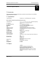
7.0 Introduction ______________________________________________________ 7-1
7.1 Specifications ____________________________________________________ 7-1
7.2 Options _________________________________________________________ 7-1
7.3 Optional Data Interfaces ____________________________________________ 7-2
7.4 Optional Overhead Interfaces ________________________________________ 7-2
Appendix A - Remote RLLP ...................................................................................... A-1
A.1 MM200 Opcode Command Set ______________________________________ A-1
A.2 Modem Command Set _____________________________________________ A-1
A.3 Detailed Command Descriptions _____________________________________ A-4
Appendix B - SNMP MIB ........................................................................................... B-1
Glossary.....................................................................................................................G-1
xii
TM086 - Rev. 4.1
MM200 High-Speed Microwave Modem
Introduction
Introduction
1
1.0 Description
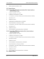
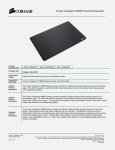
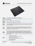
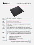
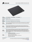
The Radyne MM200 Microwave Modem is a high-speed, multi data rate Modulator/Demodulator.
It is a single rack digital modem for point-to-point or point-to-multipoint communication links and is
ideal for microwave link upgrades or retrofits.
The MM200 utilizes a proprietary matrix modulation format that provides maximum bandwidth
efficiency and data rates up to 176 Mbps (200 Mbps optional). Increased performance is
achieved in multi-path or fading environments over conventional QAM modulation.
The MM200 offers a large variety of interfaces such as T3, E3, STS1, DVB SPI, DVB ASI,
OC3/STM-1, T1, E1, E2, 10Base T, and others.
Figure 1-1. MM200 Microwave Modem
TM086 - Rev. 4.1
1-1
Introduction
1-2
MM200 High-Speed Microwave Modem
TM086 - Rev. 4.1
MM200 High-Speed Microwave Modem
Installation
Installation
2
2.0 Installation Requirements
The MM200 is designed to be installed within any standard 19-inch equipment cabinet or rack,
and requires 2 rack unit (RU) mounting spaces (3.5 inches) vertically and 19 inches of depth.
Including cabling, a minimum of 20 inches of rack depth is required. The rear panel of the MM200
is designed to have power enter from the left and IF cabling enter from the right when viewed from
the rear of the unit. Data and control cabling can enter from either side although they are closer to
the center. The unit can be placed on a table or suitable surface if required.
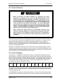
There are no user-serviceable parts or configuration settings located
inside the MM200 chassis. There is a potential shock hazard internally at
the power supply module. DO NOT open the MM200 chassis under any
circumstances.
Before initially applying power to the unit, it is a good idea to disconnect
the transmit output from the operating station equipment. This is
especially true if the current MM200 configuration settings are unknown,
where incorrect setting could disrupt existing communications traffic.
The MM200 contains a Lithium Battery. DANGER OF EXPLOSION exists if
the battery is incorrectly replaced. Replace only with the same or
equivalent type recommended by the manufacturer. Dispose of used
batteries in accordance with manufacturers instructions
2.1 Unpacking
The MM200 Modem was carefully packaged to avoid damage and should arrive complete with the
following items for proper installation:
MM200 Unit
Prime power connection
Installation and Operation Manual
TM086 - Rev. 4.1
2-1
Installation
MM200 High-Speed Microwave Modem
2.2 Removal and Assembly
If using a knife or cutting blade to open the carton, exercise caution to ensure that the blade does
not extend into the carton, but only cuts the tape holding the carton closed. Carefully unpack the
unit and ensure that all of the above items are in the carton. If the Primary AC power available at
the installation site requires a different power cord/AC connector, then arrangements to receive
the proper device will be necessary before proceeding with the installation.
The MM200 modem is shipped fully assembled and does not require removal of the covers for
any purpose in installation. Should the power cable AC connector be of the wrong type for the
installation, either the cable or the power connector end should be replaced. The power supply
itself is designed for universal application using from 100 to 240 VAC, 50-60 Hz, 1A or 37 – 75
VDC @ 4A.
2.3 Mounting Considerations
When mounted in an equipment rack, adequate ventilation must be provided. The MM200 draws
air in from the left hand side and exhausts from the right rear and side (as viewed from the front).
Do not install the unit in closed locations where this airflow will be restricted. The exhaust air must
be allowed to vent away from the unit and not be allowed to flow back into the air input. The
ambient temperature in the rack should be between 0° and 50° C, and held constant for best
equipment operation. The air available to the rack should be clean and relatively dry
Do not mount the MM200 in an unprotected outdoor location where there is direct contact with
rain, snow, wind or sun. The MM200 is designed for indoor applications only.
The only tools required for rack mounting the MM200 is a set of four rack mounting screws and
an appropriate screwdriver. Rack mount brackets are an integral part of the cast front bezel of the
unit and are not removable.
Shielded cables with the shield terminated to the conductive backshells are required in order to
meet EMC directives. Cables with insulation flammability ratings of 94 VO or better are required
in order to meet low voltage directives.
2.4 Modem Checkout
The following descriptions assume that the MM200 is installed in a suitable location with prime
power and supporting equipment available.
2-2
TM086 - Rev. 4.1
MM200 High-Speed Microwave Modem
Installation
2.4.1 Initial Power-Up
Before initial power up of the MM200, it is a good idea to disconnect the
transmit output from the operating ground station equipment. This is
especially true if the current modem configuration settings are unknown,
where incorrect setting could disrupt existing communications traffic.
New units from the factory are normally shipped in a default
configuration which includes setting the transmit carrier off.
Turn the unit ‘ON’ by applying power (DC versions), or placing the rear panel switch (above the
power entry connector) to the ‘ON’ position (AC versions). Upon initial and subsequent powerups, the MM200 microprocessor will test itself and several of its components before beginning its
main monitor/control program. These power-up diagnostics show no results if successful.
TM086 - Rev. 4.1
2-3
Installation
2-2
MM200 High-Speed Microwave Modem
TM086 - Rev. 4.1
MM200 High-Speed Microwave Modem
Theory of Operation
Theory of Operation
3
3.0 Theory of Operation
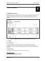
The MM200 Microwave Modem is a highly flexible platform for the transmission of high-speed
data across links such as microwave and cable. The 2 RU-rack mount unit can be supplied in
many different configurations and was designed to be expanded in the field to meet new and
changing operating conditions. Available in Duplex and Simplex Configurations, the unit can be
optioned with up to four industry standard interfaces in any combination, Diversity (requires two
chassis), maximum rates of 50, 100, 150, 175, and 200 Mbps, and world standard AC or DC
prime power.
The fully configured MM200 includes a data multiplexer/demultiplexer for interfacing to multiple
data sources, a modulator, and a demodulator. The MM200 is capable of data rates up to
200 Mbps at any of six different Quadrature Amplitude Modulation (QAM) schemes including
QAM256 (optional). The unique modulation/demodulation scheme uses multiple carriers to slow
the modulated symbol rate to up to four times slower than conventional modems. The lower
symbol rate is inherently more resilient to the multipath environment common to microwave
systems. An extremely powerful equalizer, working at the lower symbol rate, removes multipath
and is coupled with Reed Solomon Noise Reduction System to form a robust, reliable
communications link. Additionally, two receivers can be optioned with diversity cards. The two
chassis are then coupled via a high-speed data link to allow the automatic hitless switching to the
receiver with no errors. This feature can be used for standard path redundancy on long links or to
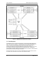
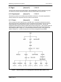
improve the capacity (via an increase in modulation mode) of an existing link. Refer to Figure 3-1
for operational block diagram.
3.1 Signal Flow
3.1.1 Interfaces
The transmit customer data interface consists of four “slots”. Each slot can accept one of a range
of industry standard interface cards including:
DVB ASI (1 to 160 Mbps)
DVB SPI (1 to 160 Mbps)
G.703 E3/DS3/STS-1
G.703 T1/E1
G.703 E2
OC3/STM-1 optical/electrical
Orderwire, 8 synchronous, 64 Kbps, RS-422 (one channel can be switched to ADPCM)
10Base T Ethernet
Data between interface slots can be Asynchronous and in any combination. Careful attention to
the maximum data rate and its relationship to bandwidth are required for the correct operating
conditions.
Some Interface Cards are capable of multiple standards such as the DS3,E3 or STS-1. These
cards can operate in any one of the standards listed. Changing to another standard simply
requires a change in the front panel configuration.
TM086 - Rev. 4.1
3-1
Theory of Operation
MM200 High-Speed Microwave Modem
Figure 3-1. MM200 Microwave Modem Block Diagram
3.1.2 Data Muxiplexer
The multiplexer works on a constant output data rate. This data rate is directly related to the
symbol rate used by the modulators. The Symbol Rate is directly related to Bandwidth of the IF
carrier. The output of the multiplexer contains Reed Solomon overhead and mux/demux
overhead. The ratio between multiplexer input data and output data is 184/204. To
accommodate changes in the data rate supplied by the customer and the constant output of the
mux, the gaps are filled with null data that is later removed by the demux. Therefore, the
customer data is completely variable up to the point where the mux overflows. Variable interfaces
like the DVB ASI can take full advantage of this feature.
The single stream output of the mux is sent to a digital splitter that can have between one and
four outputs, which corresponds to the number of RF modulators installed.
3-2
TM086 - Rev. 4.1
MM200 High-Speed Microwave Modem
Theory of Operation
Data is always evenly divided between the number of channels selected i.e. each RF modulator
runs at the same rate.
3.1.3 RF Modulators
The number of active modulators (up to the maximum number installed in the chassis, from 1 to
4) is determined by front panel selection in which case any unused modulator is “parked” or
turned off. Each modulator is capable of modulating a carrier between 50 and 90 MHz with QAM
4,16,32,64,128 or 256 (optional). The range of symbol rates per modulator is 3.5 to 7 Msps giving
a total range of 3.5 to 28 Msps. The four outputs are combined to a single IF output. Output
power is adjusted by a 1 dB step attenuator.
3.1.4 RF Demodulators
The RF Demodulators mirror the RF Modulators in their specifications. The receive signal is split
four ways each going to an independent demodulator. Again, the number of demodulators (up to
the maximum number installed in the chassis, from 1 to 4) can be set from the front panel. The
Modulator and Demodulator setup must be identical for the signal to pass.
Each demodulator has a powerful digital equalizer to remove multipath and other signal
degradations.
The Demux removes the overhead and sends the appropriate data to the appropriate interface as
identified by its unique PID (Packet Identifier). The Tx interface must match the Rx interface.
3.1.5 Diversity (Option)
When the system requires Diversity such as Space Diversity or Frequency Diversity, the receiving
site must have two independent receive signals. Each of the two MM200 chassis are required to
be optioned with a minimum of identical receivers (number of RF channels) and a diversity card.
Only one chassis needs to be optioned with interfaces if no equipment redundancy is required.
The transmit side of both chassis are completely independent from diversity operation and can
therefore be optioned in any configuration.
Data from the demux is sent to the diversity card where it is buffered and aligned in time with the
signal received from the other diversity card. Both these signals appear at the hitless switch.
Error information from all receivers is sent to the hitless switch driver where a decision is made as
to which stream to output. The output will be error-free providing one of the demodulator chassis
is receiving an error-free signal. If both chassis are receiving errored signals, the output can still
be error-free providing errors occur in different Reed-Solomon packets.
Both diversity cards send and receive data to and from the other unit, so both chassis will output
the best data stream of the two units.
3.2 Start-Up Procedures
3.2.1 Initial Start-up Procedure
1.
Turn the unit on.
2.
Set Tx Power to ‘–10 dBm’.
3.
Set the Demodulator Attenuation to ‘20 dB’.
4.
Under the Mod/Demod Test, set PRBS to ‘–2e23M’.
5.
Connect IF Out to IF In via a 75Ω Coax Cable.
TM086 - Rev. 4.1
3-3
Theory of Operation
6.
MM200 High-Speed Microwave Modem
Modem should lock with SNRs > 32 dB.
3.2.2 Sample Setups
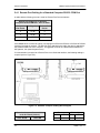
3.2.2.1 Transmitting G.703 T3 From Interface Slot 3 (other interfaces
disabled) Sample Setup
1.
In System, User Mode, set to ‘Level 2’.
2.
In Modulator, set the frequency to ’70 MHz’.
3.
In Tx Interface 3, set Control to ‘Enable’ (ensure all other interfaces are disabled).
4.
Set Interface to ‘T3’.
5.
Set Data Inv to ‘Norm’.
6.
Set Bandwidth in the Modulator Menu to ‘30,000,000’.
7.
Set the Demodulator to a frequency of ‘70 MHz’.
8.
In Rx Interface 3, set Control to ‘Enable’ (ensure all other interfaces are disabled).
9.
Set Interface to ‘T3’.
10.
Set Data Inv to ‘Norm’.
11.
Set the bandwidth in the Demodulator Menu to ‘30,000,000’.
3.2.2.2 Transmitting STM-1 From Interface Slot 1 (other interfaces
disabled) Sample Setup
1.
In System, User Mode, set to ‘Level 2’.
2.
In Modulator, set the frequency to ’70 MHz’.
3.
In Tx Interface 1, set Control to ‘Enable’ (ensure all other interfaces are disabled).
4.
Set Interface to ‘STM-1’.
5.
Set Data Inv to ‘Norm’.
6.
Set the bandwidth in the Modulator Menu to ‘30,000,000’.
7.
Set the Demodulator to a frequency of 70 MHz.
8.
In Rx Interface 1, set Control to ‘Enable’ (ensure all other interfaces are disabled).
9.
Set Interface to ‘STM-1’.
10.
Set Data Inv to ‘Norm’.
11.
Set the Bandwidth in the Demodulator Menu to ‘30,000,000’.
3.2.3 Hardware Reset
3-4
TM086 - Rev. 4.1
MM200 High-Speed Microwave Modem
Theory of Operation
This section is not yet complete.
3.3 Calculating 3dB Bandwidth of MM200 Modulated Carrier
1.
Find the combined interface data rate:
DRC = Interface 1 Data Rate + Interface 2 Data Rate + Interface 3 Data Rate + Interface 4
Data Rate
2.
Find the Total Data Rate plus R/S mux overhead, and guard band overhead:
DRT = DRC x (204/184) x 1.001
3.
Find Channel Baud Rate:
BRC = DRT /(QAM x NC)
Where NC = number of channels (one to four)
and QAM = 2 for 4 QAM
4 for 16 QAM
5 for 32 QAM
6 for 64 QAM
7 for 128 QAM
8 for 256 QAM
4.
Select Channel Spacing:
CS = from 1.1 to 1.5 times channel baud rate.
This number is usually 1.25 but may be set anywhere within the range of 1.1 to 1.5.
5.
Total 3 dB bandwidth = BRC x CS x (NC – 1) + BRC
3.4 Input Level
Each IF channel has an independent dynamic range of 15 - 20 dB. This allows greater
performance during frequency selective fades. For normal operation, the MM200 was designed
to work with radios that have automatic gain control (AGC). The radio AGC will generally use the
average power of all the IF channels to set its power unlike the MM200 that independently AGCs
on each IF channel. When setting up the input level to the MM200, use the following procedure.
1.
If the Radio has a IF output level setting, adjust to the manufactures optimum point. If
there is none, set between 0 and –10 dBm.
2.
Verify that the input to the radio is not experiencing frequency selective fading or a deep
flat fade.
3.
Set the MM200 Demodulator attenuator (in the Demod menu) so that the AGC level
display reads approximately 340 (in the Monitor, Demodulator Menu). When multiple IF
channels exist there will be differences in AGC from channel to channel. These should
only be of concern if any channel exceeds 300 or is lower than 400. The AGC display
displays the value the M&C has assigned to the channel.
This display is un-calibrated and has a useful range of approximately 300 to 655. The number is
inversely proportional to the incoming signal (a higher number indicates a lower incoming signal).
TM086 - Rev. 4.1
3-5
Theory of Operation
3-6
MM200 High-Speed Microwave Modem
TM086 - Rev. 4.1
MM200 High-Speed Microwave Modem
User Interfaces
User Interfaces
4
4.0 User Interfaces
There are four user interfaces available for the MM200. These are:
Front Panel Control.
Command Interface Control.
Terminal Interface
Ethernet SNMP
Any of these methods may be used separately or together to monitor and control the MM200.
Each of these interfaces and their respective methods are discussed separately below.
4.1 Front Panel User Interface
The front panel of the MM200 allows for complete monitor and control (M&C) of all parameters
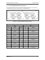
and functions via a keypad, LCD display and status LEDs.
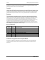
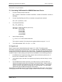
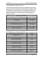
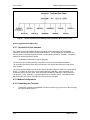
The front panel layout is shown in Figure 4−1, showing the location and labeling of the front panel.
The front panel is divided into four functional areas: the Front Panel LCD Display, the Cursor
Control Arrows, the Numeric Keypad, and the Front Panel LED Indicators, each described below
in Table 4-1.
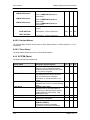
Figure 4-1. MM200 Front Panel Controls and Indicators
Table 4-1
Item No.
Description
1
Front Panel LCD Display
Displays MM200 Operating parameters and
Configuration data.
2
Cursor Control Arrows
Controls the up, down, left, and right movement
of the cursor in the Front Panel LCD Display.
3
Numeric Keypad
Allows entry of numeric data, and the Clear and
Enter function keys.
4
Front Panel LED
Indicators
Refer to Section 4.1.2 for an itemized description
of these LEDs.
TM086 - Rev. 4.1
Function
4-1
User Interfaces
MM200 High-Speed Microwave Modem
4.1.1 Front Panel LCD Display
The front panel display is a 2 line by 16-character LCD display. The display is lighted and the
brightness can be set to increase when the front panel is currently in use. The LCD display
automatically dims after a period of inactivity. The display has two distinct areas showing current
information. The upper area shows the current parameter being monitored, such as ‘Frequency’
or ‘Data Rate’. The lower line shows the current value of that parameter. The LCD display is a
single entry window into the large matrix of parameters that can be monitored and set from the
front panel.
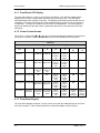
4.1.2 Cursor Control Arrows
The ‘Cursor’ or ’Arrow’ Keys (↑), (↓), (→), (←), are used to navigate the parameter currently being
monitored or controlled. Table 4-2 describes the key functions available at the front panel.
Table 4-2.
Edit Mode Key Functions (Front Panel Only)
Parameter
Type
0–9
↑
Fixed Point Changes Digit Toggles ±
Decimal
(If Signed)
↓
←
→
‘Clear’ &
←
‘Clear’ &
→
Toggles ±
(If Signed)
Moves
Cursor 1
Position
Left
Moves
Cursor 1
Position
Right
N/A
N/A
Moves
Cursor 1
Position
Left
Moves
Cursor 1
Position
Right
N/A
N/A
Unsigned Changes Digit Increments Decrements
Hexadecimal
Digit Value Digit Value
Enumerated
N/A
Previous
Value in
List
Next
Value in
List
N/A
N/A
N/A
N/A
N/A
N/A
Moves
Cursor 1
Position
Left
Moves
Cursor 1
Position
Right
N/A
N/A
IP Address Changes Digit Increments Decrements
Digit Value Digit Value
Moves
Cursor 1
Position
Left
Moves
Cursor 1
Position
Right
N/A
N/A
Text Strings
Moves
Cursor 1
Position
Left
Moves
Cursor 1
Position
Right
Clears to
Left of
Cursor
Inclusive
Clears to
Right of
Cursor
Inclusive
Date/ Time Changes Digit
Changes
Character
Increments Decrements
Character
Character
Value
Value
4.1.3 Front Panel Keypad
The Front Panel Keypad consists of a 10-key numeric entry with two additional keys for the ‘Enter’
and ‘Clear’ functions. Table 4-2 describes the key functions available at the front panel.
4-2
TM086 - Rev. 4.1
MM200 High-Speed Microwave Modem
User Interfaces
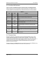
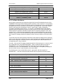
4.1.4 Front Panel LED Indicators
There are 12 LEDs on the MM200 front panel to indicate the status of the MM200’s operation
(refer to Table 4-3). The LED colors maintain a consistent meaning. Green signifies that the
indication is appropriate for normal operation, Yellow means that there is a condition not proper
for normal operation, and Red indicates a fault condition that will result in lost communications.
Table 4-3
LED
Color
Function
Transmit On
Green
Major Alarm
Red
Minor Alarm
Yellow
Indicates a transmit warning condition exists.
Test Mode
Yellow
Indicates the modulator is involved in a current test mode
activity.
Signal Lock
Green
Indicates the modem has received a signal and is locked
Major Alarm
Red
Minor Alarm
Yellow
Receive learning condition.
Test Mode
Yellow
Indicates the modem is involved in a current test mode
activity.
Power
Green
Indicates the MM200 unit is currently powered-up.
Fault
Red
Event
Yellow
Indicates that a new event has been logged into the Event
Buffer.
Remote
Green
Indicates that the unit is set to respond to the remote control
or terminal input.
Indicates the MM200 Transmitter is turned on.
Indicates that the transmit direction has failed, losing traffic.
Receive direction failed.
Indicates a general equipment fault.
4.1.5 Parameter Setup
Use the four arrow keys, to navigate the menu tree and select the parameter to be set. After
arriving at a parameter that needs to be modified, depress <ENTER>. The first space of the
modifiable parameter highlights (blinks) and is ready for a new parameter to be entered. After
entering the new parameter using the keypad, depress <ENTER> to lock in the new parameter. If
a change needs to be made prior to pressing <ENTER>, depress <CLEAR> and the display
defaults back to the original parameter. Depress <ENTER> again and re-enter the new
parameters followed by <ENTER>.
Following a valid input, the MM200 will place the new setting into the nonvolatile EEPROM making
it available immediately and available the next time the unit is powered-up.
TM086 - Rev. 4.1
4-3
User Interfaces
MM200 High-Speed Microwave Modem
4.2 Front Panel Control Screen Menus
The Front Panel Control Screen Menus are listed below. The MM200 Microwave Modem may be
operated in three different levels:
Level 0 - is for specialized factory configurations. Every screen is available including
those used for factory calibration and diagnostics.
Level 1 – includes those screens necessary for field maintenance.
Level 2 – is the default setting and is shipped from the factory in this mode. The screens
are available that provide the quickest form of setup and use.
Note: Screens Menus are listed below by level (L0, L1, and L2) and may be Read/Write
(RW) or Read Only (RO).
4.3 Level 2 Menu Screens
Level 2 menus screens allow for the quickest operation and system setup.
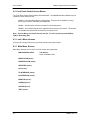
4.3.1 Main Menu Screens
Main Menu Screens (one of which is a Title Screen) are listed below:
MM-200 MODULATOR
Title Screen:
Not a modifiable screen.
MODULATOR (menu):
DEMODULATOR (menu):
REPEATER (menu):
APC (menu):
TX INTERFACE (menu):
RX INTERFACE (menu):
MONITOR (menu):
ALARMS (menu):
SYSTEM (menu):
TEST (menu):
4-4
TM086 - Rev. 4.1
MM200 High-Speed Microwave Modem
User Interfaces
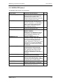
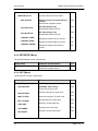
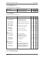
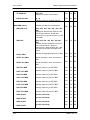
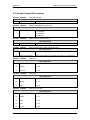
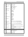
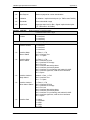
4.3.2 MODULATOR (menu) *
The Modulator Menu Screens are listed below:
Screen Name
Selections and Descriptions
L2
FREQUENCY (Hz)
{50 – 90 MHz}
Controls the current center band of the
operating frequency width, or the
individual channel frequency if the System
Frequency Control is set to ‘User’.
{Auto, 1 - 4}
Controls the number of channel cards
where 0 = auto, and 1 – 4 = the number of
cards. Increase this number for better
performance. Lower this number for
better bandwidth efficiency.
{3.5 – 28 Msps}
Controls the total Symbol Rate.
{QAM4, QAM16, QAM32, QAM64,
QAM128, QAM256}
Displays the current Modulation Scheme.
Performance is increased by using the
lowest QAM Mode possible for the
required bandwidth.
Enters the 3 dB bandwidth of the
modulated IF Output. When the radio
must meet a particular spectral mask, set
this number to something below the
masks 3 dB points (i.e. 5% less). For best
performance, do not allow the MM200s
bandwidth to be greater than the radios 1
dB bandwidth.
Displays the percentage of the data being
transferred that is being used by the
selected interfaces. Must be less than
100% (Maximize this number for best
bandwidth efficiency by lowering the
symbol rate, QAM Mode, or the number of
channels).
Displays the maximum total data rate that
is useable for the current settings.
{Normal, Inverted}
Used for inverting the spectrum. If the
unit cannot lock to the signal after passing
through the radio, try these settings.
{0 to –25 dBm}
Sets the IF Output Power in 1 dB steps.
{Off, On}
Forces the Carrier to Off or On.
RW
CHANNELS
SYMB RATE (SPS)
MODULATION
BANDWIDTH (Hz)
UTILIZATION (%) *
MAX PAYLOAD (Hz)
SPECTRUM
TX POWER
TX ENABLE
TM086 - Rev. 4.1
RW
RO
RO
RW
RO
RO
RW
RW
RW
4-5
User Interfaces
MM200 High-Speed Microwave Modem
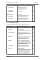
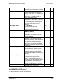
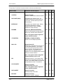
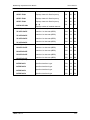
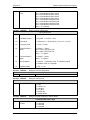
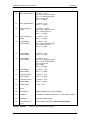
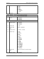
4.3.3 DEMODULATOR (menu)
The Demodulator Menu Screens are listed below:
Screen Name
Selections and Descriptions
L2
FREQUENCY (Hz)
{50 – 90 MHz}
Displays the current center band of the
operating frequency width.
{Auto, 1 – 4, Debug}
Controls the number of channel cards
where 0 = auto, and 1 – 4 = the number of
cards. Increase this number for better
performance. Lower this number for
better bandwidth efficiency.
{3.5 – 28 Msps}
Controls the total Symbol Rate.
{QAM4, QAM16, QAM32, QAM64,
QAM128, QAM256}
Displays the current Demodulation
Scheme.
Displays the frequency difference between
the highest channel’s upper 3-dB point
and the lowest channel’s lower 3-dB point.
Displays the percentage of the data being
transferred that is being used by the
selected interfaces. Must be less than
100%. Maximize this number for best
bandwidth efficiency by lowering the
symbol rate, QAM Mode, or the number of
channels.
Displays the maximum total data rate that
is useable for the current settings.
{Normal, Inverted}
{0 - 31}
Sets the Demodulator Input IF Attenuator
in 1 dB steps.
The Demodulator Acquisition Frequency
range can be set by the user. This is
required at higher QAM rates when using
radios with significant frequency drift. As
QAM rates increase, the ability of the
receiver to acquire to a signal that is offset
from the programmed demodulator
frequency is reduced. At QAM256 the
acquisition window can be as low as ± 50
kHz. Yet at QAM4, the window can be
over ± 1 MHz. This range can be further
reduced by noise or degraded receive
signals.
RW
CHANNELS
SYMB RATE (SPS)
DEMODULATION
BANDWIDTH (Hz)
UTILIZATION (%)
MAX PAYLOAD (Hz)
SPECTRUM
ATTENUATION
ACQUISITION (menu):
RW
RO
RO
RW
RO
RO
RW
RW
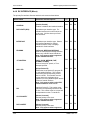
When trying to acquire a signal, the
MM200 follows this procedure:
1. Try to acquire at the Demodulator
Programmed Frequency.
2. Continue to try to acquire for the length
4-6
TM086 - Rev. 4.1
MM200 High-Speed Microwave Modem
User Interfaces
of time set in ACQ DELAY (sec).
3. Step the Demodulator frequency up
one step size programmed in ACQ
STEP (KHz).
4. Repeat Steps 1 through 3 until the
Demodulator Frequency exceeds the +
side of the ACQ BW.
5. Set the Demodulator to the negative
side of ACQ BW.
6. Repeat until demodulator acquires.
Once acquired, the demodulator will
have an offset between the frequency
at which the demodulator is set and the
incoming signal frequency. This is due
to demodulator frequency acquisition
window and radio drift. This can cause
degraded performance and, in the case
of radio drift, possible loss of lock. To
overcome this, once acquired, the
demodulator reduces this offset to 0 Hz
by slowly incrementing/decrementing
the demodulator frequency. The speed
can be adjusted by adjusting the
TRACK STEP (Hz). It is suggested
that this parameter normally be set to
10 Hz.
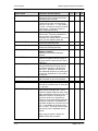
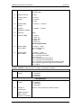
ACQ CONTROL
{Off, Acquire}
Always set to Acquire.
RW
ACQ BW (kHz)
{50 KHz – 400 kHz}
Sets the ± acquisition bandwidth. There is
a tradeoff between this number and
acquisition speed.
RW
ACQ DELAY (sec)
{10 – 255 sec}
Sets the time that the demodulator stays
at a frequency before trying the next step.
RW
REACQ DELAY (sec)
{10 – 255 sec}
Sets the time that the demodulator
remains at frequency after it first loses
lock.
RW
ACQ STEP (kHz)
{10 – 100 kHz}
Sets the frequency step size the
demodulator will take when trying to
acquire.
RW
TRACKING STEP (Hz)
{10 – 100 Hz}
Sets the step size that the demodulator
will use to remove the frequency error of a
locked signal. Normally set to 10 Hz.
RW
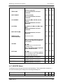
DIVERSITY (menu):
MODE
TM086 - Rev. 4.1
Diversity
{Disable, Auto, Force A, Force B}
RW
4-7
User Interfaces
MM200 High-Speed Microwave Modem
Controls the diversity mode.
MONITOR (menu):
Diversity channel and FIFO status.
MUX STATUS
{Unused, Channel A, Channel B, Null
Frames}
Specifies the multiplexer status.
RW
FIFO A STATUS
{No Flags, Empty, Full}
Specifies the status of FIFO A.
RW
FIFO B STATUS
{No Flags, Empty, Full}
Specifies the status of FIFO B.
RW
Displays the Channel A error counter.
RO
Displays the Channel B error counter.
RO
Displays the Channel A and B error
counter.
RO
CHANNEL A ERR
CHANNEL B ERR
CHANNEL AB ERR
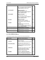
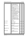
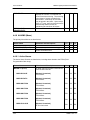
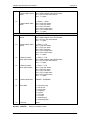
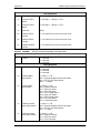
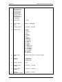
4.3.4 REPEATER (Menu)
The primary Repeater screen is listed below:
Screen Name
Selections and Descriptions
L2
MODE
{Off, On}
Enables the repeater feature.
RW
4.3.4 APC (Menu)
The primary APC screen is listed below:
Screen Name
Selections and Descriptions
TRANSMIT (menu):
APC Transmit settings.
XMT CONTROL
{TXDOWN, TXUP, AUTO}
Controls the local TX level.
RW
MAX TX LEVEL
Sets the maximum TX power level.
RW
MIN TX LEVEL
Shows the minimum TX power level.
RO
DEF TX LEVEL
Sets the default TX power level.
RW
STEP SIZE
Sets the TX power step size.
RW
Sets the power level range.
RW
Sets the TX power step speed.
RW
APC RANGE
APC SPEED
4-8
L2
TM086 - Rev. 4.1
MM200 High-Speed Microwave Modem
RECEIVE (menu):
User Interfaces
APC Receive settings.
RCV CONTROL
{RXDOWN, RXUP, AUTO}
Controls the remote TX level.
RW
LEVEL (dBm)
Desired RX power level.
RW
HYSTERESIS
APC Hysteresis.
RW
MONITOR (menu):
APC Monitor.
XMT STATUS
{NOCHANGE, TXDOWN, TXUP}
Displays APC transmit status.
RO
RCV STATUS
{NOCHANGE, RXDOWN, RXUP}
Displays APC receive status.
RO
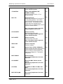
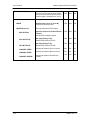
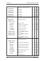
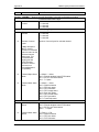
4.3.5 TX INTERFACE (Menu)
The primary Tx Interface Screens and their sub-menus as listed below:
Screen Name
Selections and Descriptions
TX INTRFC1 (menu):
Transmit Interface 1
L2
CONTROL
{Disable, Enable}
Enables or disables the installed interface.
RW
DATA RATE (BPS)
Dependant upon interface type. For
variable interfaces, this unit must be set
by the user. Will not show up on fixed
rate interfaces.
RW
INTERFACE
Dependant upon interface type. Selects
the interface standard for multiple
standard interface card, or displays
standard for fixed interfaces.
RW
FRAMING
{Unframed, MPEG188, MPEG204}
Used for DVB Interface framing selection.
Shows only in DVB Framed Interfaces.
Note: Only appears when supported
by the installed interface.
RW
JIT CONTROL
{NORMAL, STAMP2, STAMP3}
Normal or Time-Stamped packets.
RW
NULL PID
{2-Byte Packet ID}
Defines the 2-byte packet ID, program ID
for null padding packets. This number
must match the corresponding receive
demux null PID. This number must be
unique and not be duplicated by an
interface PID or any DVB transport stream
RW
TM086 - Rev. 4.1
4-9
User Interfaces
MM200 High-Speed Microwave Modem
PIDs on a framed interface.
Note: Only appears when using DVB
Framed Interfaces such as L0I.
CLK POLARITY
{Normal, Inverted}
Sets the polarity of the clock.
Note: Only appears when supported
by the installed interface.
RW
DATA INVERT
{Normal, Inverted}
Sets the polarity of the data.
RW
Note: Only appears when supported
by the installed interface.
BB LOOP
{Normal, Inverted}
Baseband Loopback. Not yet
implemented, for future expansion.
VOLUME
{0 - 255}
Allows the user to set volume level
(Orderwire only).
Note: Only appears when supported
by the installed interface.
Transmit Interface 2. Refer to TX
INTRFC1 (menu) for descriptions.
Transmit Interface 3. Refer to TX
INTRFC1 (menu) for descriptions.
Transmit Interface 4. Refer to TX
INTRFC1 (menu) for descriptions.
RW
RW
TX INTRFC2 (menu)
TX INTRFC3 (menu)
TX INTRFC4 (menu)
4.3.6 RX INTERFACE (Menu)
The primary Rx Interface Screens and their sub-menus as listed below:
Screen Name
Selections and Descriptions
RX INTRFC1
Receive Interface 1
4-10
L2
CONTROL
{Disable, Enable}
Enables or disables the installed interface.
RW
DATA RATE (BPS)
Dependant upon interface type. For
variable interfaces, this unit must be set
by the user. Will not show up on fixed
rate interfaces.
RW
INTERFACE
Dependant upon interface type. Selects
the interface standard for multiple
standard interface card, or displays
standard for fixed interfaces.
RW
FRAMING
{Unframed, MPEG188, MPEG204}
Used for DVB Interface framing selection.
Shows only in DVB Framed Interfaces.
RW
TM086 - Rev. 4.1
MM200 High-Speed Microwave Modem
User Interfaces
Note: Only appears when supported
by the installed interface.
JIT CONTROL
{INCH, SLOW, MEDIUM, FAST,
STAMP2, STAMP3}
Clock recovery DLL speed, or TimeStamped packets.
RW
NULL PID
{2-Byte Packet ID}
Defines the 2-byte packet ID, program ID
for null padding packets. This number
must match the corresponding receive
demux null PID. This number must be
unique and not be duplicated by an
interface PID or any DVB transport stream
PIDs on a framed interface.
RW
Note: Only appears when using DVB
Framed Interfaces such as L0I.
CLK POLARITY
{Normal, Inverted}
Sets the polarity of the clock.
Note: Only appears when supported
by the installed interface.
RW
DATA INVERT
{Normal, Inverted}
Sets the polarity of the data.
Note: Only appears when supported
by the installed interface.
RW
TERR LOOP
{Normal, Loopback}
Interface Loopback
RW
PRBS
{Normal, Ones, PAT001, PRBS2047}
Breaks the data path and inserts a pseudo
random sequence into the modulators.
‘None’ is used for normal operation, the
others are for Radyne Inc. Corporation
configuration.
RW
BUFF ENABLE
{Disable, Enable}
Not currently implemented, for future
expansion.
RW
CLK SOURCE
{RxClk, Ext BNC, Ext Bal, Internal,
TxCLK}
Not currently implemented, for future
expansion.
RW
CLK FREQ
{2.048 MHz, 5.0 MHz, 10.0 MHz, Data
Rate}
Not currently implemented, for future
expansion.
RW
BUFF DEPTH (MS)
Not currently implemented, for future
expansion.
RW
TM086 - Rev. 4.1
4-11
User Interfaces
MM200 High-Speed Microwave Modem
PRESS CLR TO
CENTER BUFFER
Centers the buffer.
RW
VOLUME
{0 - 255}
Allows the user to set volume level
(Orderwire only).
Note: Only appears when supported
by the installed interface.
RW
BYTE GAP
{0 - 255}
Allows the user to set ASI byte gapping.
Set to 0 for Burst mode. (ASI Interfaces
that support Byte Gap only).
Receive Interface 2. Refer to RX
INTRFC1 (menu) for descriptions.
Receive Interface 3. Refer to RX
INTRFC1 (menu) for descriptions.
Receive Interface 4. Refer to RX
INTRFC1 (menu) for descriptions.
RW
RX INTRFC2
RX INTRFC3
RX INTRFC4
4.4 All Level Menu Screens
4.4.1 Main Menu Screens
Main Menu Screens (one of which is a Title Screen) are listed below:
MM-200 MODULATOR
Title Screen:
Not a modifiable screen.
MODULATOR (menu):
DEMODULATOR (menu):
REPEATER (menu):
APC (menu):
TX INTERFACE (menu):
RX INTERFACE (menu):
MONITOR (menu):
ALARMS (menu):
SYSTEM (menu):
TEST (menu):
4.4.2 MODULATOR (menu) *
The Modulator Menu Screens are listed below:
Screen Name
Selections and Descriptions
L0
L1
L2
FREQUENCY (Hz)
{50 – 90 MHz}
Controls the current center band of the
RW
RW
RW
4-12
TM086 - Rev. 4.1
MM200 High-Speed Microwave Modem
CHANNELS
SEPARATION
DATA RATE (BPS)
SYMB RATE (SPS)
MODULATION
BANDWIDTH (Hz)
UTILIZATION (%) *
MAX PAYLOAD (Hz)
SPECTRUM
TX POWER
TX ENABLE
operating frequency width, or the
individual channel frequency if the System
Frequency Control is set to ‘User’.
{Auto, 1 - 4}
Controls the number of channel cards
where 0 = auto, and 1 – 4 = the number of
cards. Increase this number for better
performance. Lower this number for
better bandwidth efficiency.
{100% - 150%}
Default 125%. Selects the IF Frequency
Separation between channels expressed
as a percentage of the channel symbol
rate or the symbol rate/number of
channels.
{7 – 200 Mbps}
Controls the total Data Rate.
{3.5 – 28 Msps}
Controls the total Symbol Rate.
{QAM4, QAM16, QAM32, QAM64,
QAM128, QAM256}
Displays the current Modulation Scheme.
Performance is increased by using the
lowest QAM Mode possible for the
required bandwidth.
Enters the 3 dB bandwidth of the
modulated IF Output. When the radio
must meet a particular spectral mask, set
this number to something below the
masks 3 dB points (i.e. 5% less). For best
performance, do not allow the MM200s
bandwidth to be greater than the radios 1
dB bandwidth.
Displays the percentage of the data being
transferred that is being used by the
selected interfaces. Must be less than
100% (Maximize this number for best
bandwidth efficiency by lowering the
symbol rate, QAM Mode, or the number of
channels).
Displays the maximum total data rate that
is useable for the current settings.
{Normal, Inverted}
Used for inverting the spectrum. If the
unit cannot lock to the signal after passing
through the radio, try these settings.
{0 to –25 dBm}
Sets the IF Output Power in 1 dB steps.
{Off, On}
Forces the Carrier to Off or On.
User Interfaces
RW
RW
RW
RW
RW
RO
RW
RW
RO
RW
RW
RO
RO
RO
RW
RO
RO
RO
RO
RO
RO
RW
RW
RW
RW
RW
RW
RW
RW
RW
4.4.3 DEMODULATOR (menu)
The Demodulator Menu Screens are listed below:
TM086 - Rev. 4.1
4-13
User Interfaces
MM200 High-Speed Microwave Modem
Screen Name
Selections and Descriptions
L0
L1
L2
FREQUENCY (Hz)
{50 – 90 MHz}
Displays the current center band of the
operating frequency width.
{Auto, 1 - 4}
Controls the number of channel cards
where 0 = auto, and 1 – 4 = the number
of cards. Increase this number for better
performance. Lower this number for
better bandwidth efficiency.
{100% - 150%}
Selects the IF Frequency Separation in
percent, which is the additional
bandwidth percentage that the carrier will
cover over the original symbol rate.
{7 – 200 Mbps}
Controls the total Data Rate.
{3.5 – 28 Msps}
Controls the total Symbol Rate.
{QAM4, QAM16, QAM32, QAM64,
QAM128, QAM256}
Displays the current Demodulation
Scheme.
Displays the frequency difference
between the highest channel’s upper 3dB point and the lowest channel’s lower
3-dB point.
Displays the percentage of the data
being transferred that is being used by
the selected interfaces. Must be less
than 100%. Maximize this number for
best bandwidth efficiency by lowering the
symbol rate, QAM Mode, or the number
of channels.
Displays the maximum total data rate
that is useable for the current settings.
{Normal, Inverted}
{0 - 31}
Sets the Demodulator Input IF Attenuator
in 1 dB steps.
The Demodulator Acquisition Frequency
range can be set by the user. This is
required at higher QAM rates when using
radios with significant frequency drift. As
QAM rates increase, the ability of the
receiver to acquire to a signal that is
offset from the programmed demodulator
frequency is reduced. At QAM256 the
acquisition window can be as low as ± 50
kHz. Yet at QAM4, the window can be
over ± 1 MHz. This range can be further
reduced by noise or degraded receive
signals.
RW
RW
RW
RW
RW
RW
RW
RW
CHANNELS
SEPARATION
DATA RATE (BPS)
SYMB RATE (SPS)
DEMODULATION
BANDWIDTH (Hz)
UTILIZATION (%)
MAX PAYLOAD (Hz)
SPECTRUM
ATTENUATION
ACQUISITION (menu):
RO
RW
RW
RO
RW
RW
RO
RO
RO
RW
RO
RO
RO
RO
RO
RO
RW
RW
RW
RW
RW
RW
When trying to acquire a signal, the
MM200 follows this procedure:
4-14
TM086 - Rev. 4.1
MM200 High-Speed Microwave Modem
User Interfaces
1. Try to aquifer at the Demodulator
Programmed Frequency.
2. Continue to try to Acquire for the
length of time set in ACQ DELAY
(sec).
3. Step the Demodulator frequency up
one step size programmed in ACQ
STEP (KHz).
4. Repeat Steps 1 through 3 until the
Demodulator Frequency exceeds the
+ side of the ACQ BW.
5. Set the Demodulator to the negative
side of ACQ BW.
6. Repeat until demodulator acquires.
Once acquired, the demodulator will
have an offset between the frequency
at which the demodulator is set and
the incoming signal frequency. This is
due to demodulator frequency
acquisition window and radio drift.
This can cause degraded
performance and, in the case of radio
drift, possible loss of lock. To
overcome this, once acquired, the
demodulator reduces this offset to 0
Hz by slowly
incrementing/decrementing the
demodulator frequency. The speed
can be adjusted by adjusting the
TRACK STEP (Hz). It is suggested
that this parameter normally be set to
10 Hz.
ACQ CONTROL
ACQ BW (kHz)
ACQ DELAY (sec)
REACQ DELAY (sec)
ACQ STEP (kHz)
TM086 - Rev. 4.1
{Off, Acquire}
Always set to Acquire.
RW
RW
RW
{50 KHz – 400 kHz}
Sets the ± acquisition bandwidth. There
is a tradeoff between this number and
acquisition speed.
RW
RW
RW
{10 – 255 sec}
Sets the time that the demodulator stays
at a frequency before trying the next
step.
RW
RW
RW
{10 – 255 sec}
Sets the time that the demodulator
remains at frequency after it first loses
lock.
RW
RW
RW
{10 – 100 kHz}
Sets the frequency step size the
demodulator will take when trying to
acquire.
RW
RW
RW
4-15
User Interfaces
TRACKING STEP (Hz)
DIVERSITY (menu):
{10 – 100 Hz}
Sets the step size that the demodulator
will use to remove the frequency error of
a locked signal. Normally set to 10 Hz.
RW
RW
RW
RW
RW
RW
Diversity
MODE
{Disable, Auto, Force A, Force B}
Controls the diversity mode.
MONITOR (menu):
Diversity channel and FIFO status.
MUX STATUS
{Unused, Channel A, Channel B, Null
Frames}
Specifies the multiplexer status.
RW
RW
RW
FIFO A STATUS
{No Flags, Empty, Full}
Specifies the status of FIFO A.
RW
RW
RW
{No Flags, Empty, Full}
Specifies the status of FIFO B.
RW
RW
RW
Displays the Channel A error counter.
RO
RO
RO
Displays the Channel B error counter.
RO
RO
RO
Displays the Channel A and B error
counter.
RO
RO
RO
FIFO B STATUS
CHANNEL A ERR
CHANNEL B ERR
CHANNEL AB ERR
4-16
MM200 High-Speed Microwave Modem
TM086 - Rev. 4.1
MM200 High-Speed Microwave Modem
User Interfaces
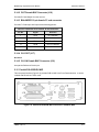
4.4.4 REPEATER (menu)
The Repeater Menu Screen is listed below:
Screen Name
Selections and Descriptions
L0
L1
L2
MODE
{Off, On}
Enables the repeater feature.
RW
RW
RW
L0
L1
L2
4.3.4 APC (Menu)
The primary APC screen is listed below:
Screen Name
Selections and Descriptions
TRANSMIT (menu):
APC Transmit settings.
XMT CONTROL
{TXDOWN, TXUP, AUTO}
Controls the local TX level.
RW
RW
RW
MAX TX LEVEL
Sets the maximum TX power level.
RW
RW
RW
MIN TX LEVEL
Displays the minimum TX power level.
RO
RO
RO
DEF TX LEVEL
Sets the default TX power level.
RW
RW
RW
STEP SIZE
Sets the TX power step size.
RW
RW
RW
Sets the TX APC range
RW
RW
RW
Sets the TX power step speed.
RW
RW
RW
APC RANGE
APC SPEED
RECEIVE (menu):
APC Receive settings.
RCV CONTROL
{RXDOWN, RXUP, AUTO}
Controls the remote TX level.
RW
RW
RW
LEVEL (dBm)
Desired RX power level.
RW
RW
RW
HYSTERESIS
APC Hysteresis.
RW
RW
RW
MONITOR (menu):
APC Monitor.
XMT STATUS
{NOCHANGE, TXDOWN, TXUP}
Displays APC transmit status.
RO
RO
RO
RCV STATUS
{NOCHANGE, RXDOWN, RXUP}
Displays APC receive status.
RO
RO
RO
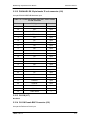
4.4.5 TX INTERFACE (Menu)
TM086 - Rev. 4.1
4-17
User Interfaces
MM200 High-Speed Microwave Modem
The primary Tx Interface Screens and their sub-menus as listed below:
Screen Name
Selections and Descriptions
TX INTRFC1 (menu):
Transmit Interface 1
L0
L1
L2
CONTROL
{Disable, Enable}
Enables or disables the installed interface.
RW
RW
RW
DATA RATE (BPS)
Dependant upon interface type. For
variable interfaces, this unit must be set
by the user. Will not show up on fixed
rate interfaces.
RW
RW
RW
INTERFACE
Dependant upon interface type. Selects
the interface standard for multiple
standard interface card, or displays
standard for fixed interfaces.
RW
RW
RW
FRAMING
{Unframed, MPEG188, MPEG204}
Used for DVB Interface framing selection.
Shows only in DVB Framed Interfaces.
RW
RW
RW
Note: Only appears when supported
by the installed interface.
JIT CONTROL
{NORMAL, STAMP2, STAMP3}
Normal or Time-Stamped packets.
RW
RW
RW
NULL PID
{2-Byte Packet ID}
Defines the 2-byte packet ID, program ID
for null padding packets. This number
must match the corresponding receive
demux null PID. This number must be
unique and not be duplicated by an
interface PID or any DVB transport stream
PIDs on a framed interface.
RW
RW
RW
Note: Only appears when using DVB
Framed Interfaces such as L0I.
4-18
PID
Interface Packet ID. This number must
match the corresponding interface at the
Rx site. This number must be unique and
not duplicated on other Tx interfaces.
RW
CLK POLARITY
{Normal, Inverted}
Sets the polarity of the clock.
Note: Only appears when supported
by the installed interface.
RW
RW
RW
DATA INVERT
{Normal, Inverted}
Sets the polarity of the data.
RW
RW
RW
BB LOOP
{Normal, Inverted}
Baseband Loopback. Not yet
RW
RW
RW
TM086 - Rev. 4.1
MM200 High-Speed Microwave Modem
User Interfaces
implemented, for future expansion.
VOLUME
TX INTRFC2 (menu)
TX INTRFC3 (menu)
TX INTRFC4 (menu)
TM086 - Rev. 4.1
{0 - 255}
Allows the user to set volume level
(Orderwire only).
Transmit Interface 2. Refer to TX
INTRFC1 (menu) for descriptions.
Transmit Interface 3. Refer to TX
INTRFC1 (menu) for descriptions.
Transmit Interface 4. Refer to TX
INTRFC1 (menu) for descriptions.
RW
RW
RW
4-19
User Interfaces
MM200 High-Speed Microwave Modem
4.4.6 RX INTERFACE (Menu)
The primary Rx Interface Screens and their sub-menus as listed below:
Screen Name
Selections and Descriptions
RX INTRFC1
Receive Interface 1
L1
L2
CONTROL
{Disable, Enable}
Enables or disables the installed interface.
RW
RW
RW
DATA RATE (BPS)
Dependant upon interface type. For
variable interfaces, this unit must be set
by the user. Will not show up on fixed
rate interfaces.
RW
RW
RW
INTERFACE
Dependant upon interface type. Selects
the interface standard for multiple
standard interface card, or displays
standard for fixed interfaces.
RW
RW
RW
FRAMING
{Unframed, MPEG188, MPEG204}
Used for DVB Interface framing selection.
Shows only in DVB Framed Interfaces.
Note: Only appears when supported
by the installed interface.
RW
RW
RW
JIT CONTROL
{INCH, SLOW, MEDIUM, FAST,
STAMP2, STAMP3}
Clock recovery DLL speed, or TimeStamped packets.
RW
RW
RW
NULL PID
{2-Byte Packet ID}
Defines the 2-byte packet ID, program ID
for null padding packets. This number
must match the corresponding receive
demux null PID. This number must be
unique and not be duplicated by an
interface PID or any DVB transport stream
PIDs on a framed interface.
Note: Only appears when using DVB
Framed Interfaces such as L0I.
RW
RW
RW
Interface Packet ID. This number must
match the corresponding interface at the
Rx site. This number must be unique and
not duplicated on other Tx interfaces.
RW
{Normal, Inverted}
Sets the polarity of the clock.
Note: Only appears when supported
by the installed interface.
RW
RW
RW
{Normal, Inverted}
Sets the polarity of the data.
Note: Only appears when supported
RW
RW
RW
PID
CLK POLARITY
DATA INVERT
4-20
L0
TM086 - Rev. 4.1
MM200 High-Speed Microwave Modem
User Interfaces
by the installed interface.
{Normal, Loopback}
Not yet implemented, for future
expansion.
RW
RW
RW
BUFF ENABLE
{Disable, Enable}
Not yet implemented, for future
expansion.
RW
RW
RW
CLK SOURCE
{RxClk, Ext BNC, Ext Bal, Internal,
TxCLK}
Not yet implemented, for future
expansion.
RW
RW
RW
CLK FREQ
{2.048 MHz, 5.0 MHz, 10.0 MHz, Data
Rate}
Not yet implemented, for future
expansion.
RW
RW
RW
BUFF DEPTH (MS)
Not yet implemented, for future
expansion.
RW
RW
RW
PRESS CLR TO
CENTER BUFFER
Centers the buffer.
RW
RW
RW
TERR LOOP
Note: Rx Interface between Data and
Volume may need to be masked off
until needed.
VOLUME
{0 - 255}
Allows the user to set volume level
(Orderwire only).
Note: Only appears when supported
by the installed interface.
RW
RW
RW
BYTE GAP
{0 - 255}
Allows the user to set ASI byte gapping.
Set to 0 for Burst mode. (ASI Interfaces
that support Byte Gap only).
Receive Interface 2. Refer to RX
INTRFC1 (menu) for descriptions.
Receive Interface 3. Refer to RX
INTRFC1 (menu) for descriptions.
Receive Interface 4. Refer to RX
INTRFC1 (menu) for descriptions.
RW
RW
RW
RX INTRFC2
RX INTRFC3
RX INTRFC4
4.4.7 MONITOR (Menu)
The Monitor Screens and their sub-menus are listed below. Those marked with an asterisk (*)
are used for detailed system debug when consulting with Radyne Inc. .
Screen Name
Selections and Descriptions
MON MOD (menu)
Monitors the state of the modulator.
TM086 - Rev. 4.1
L0
L1
L2
4-21
User Interfaces
TX ENABLED
OFF, ON}
Displays TX Power Control Status
RO
RO
RO
INSTALLED CHs
{0 – 4}
Displays number of installed channels
RO
RO
RO
RO
RO
RO
MON DMD (menu):
4-22
MM200 High-Speed Microwave Modem
Monitors the state of the demodulator.
DMD SNR X 10
{000 – 999 000 – 999 000 – 999 000 999}
Displays the demodulator signal-to-noise
ratio for each channel. Divide each
number by 10 to get the dB value (i.e. 355
= 35.5 dB).
DMD AGC
{000 – 655 000 – 655 000 – 655 000 655}
Displays a relative indication of the AGC
level of each channel. Optimum
performance is approximately 320 – 420.
The lower the number, the higher the IF
signal.
RO
RO
RO
LEVEL (dBm)
Monitors the aggregate input level in dBm.
RO
RO
RO
LEVEL 1&2 (dBm)
Monitor channels 1 and 2 input levels in
dBm.
RO
RO
RO
LEVEL 3&4 (dBm)
Monitor channels 3 and 4 input levels in
dBm.
RO
RO
RO
PRE FEC1 BER
Displays channel 1 pre FEC BER.
RO
RO
RO
POST FEC1 BER
Displays channel 1 post FEC BER.
RO
RO
RO
PRE FEC2 BER
Displays channel 2 pre FEC BER.
RO
RO
RO
POST FEC2 BER
Displays channel 2 post FEC BER.
RO
RO
RO
PRE FEC3 BER
Displays channel 3 pre FEC BER.
RO
RO
RO
POST FEC3 BER
Displays channel 3 post FEC BER.
RO
RO
RO
PRE FEC4 BER
Displays channel 4 pre FEC BER.
RO
RO
RO
POST FEC4 BER
Displays channel 4 post FEC BER.
RO
RO
RO
DMD1 STATE
{Locked, Unlocked}
RO
RO
RO
DMD2 STATE
{Locked, Unlocked}
RO
RO
RO
DMD3 STATE
{Locked, Unlocked}
RO
RO
RO
DMD4 STATE
{Locked, Unlocked}
RO
RO
RO
TM086 - Rev. 4.1
MM200 High-Speed Microwave Modem
User Interfaces
OFFST FRQ1
Displays channel 1 offset frequency
RO
RO
RO
OFFST FRQ2
Displays channel 2 offset frequency
RO
RO
RO
OFFST FRQ3
Displays channel 3 offset frequency
RO
RO
RO
OFFST FRQ4
Displays channel 4 offset frequency
RO
RO
RO
INSTALLED CHs
{0 – 4}
Displays number of installed channels
Monitors the multiplexor
RO
RO
RO
TX INTF1 RATE
Interface 1 tx data rate (KBPS)
RO
RO
RO
TX INTF2 RATE
Interface 2 tx data rate (KBPS)
RO
RO
RO
TX INTF3 RATE
Interface 3 tx data rate (KBPS)
RO
RO
RO
TX INTF4 RATE
MON DMX (menu)
Interface 4 tx data rate (KBPS)
RO
RO
RO
MON MUX (menu)
Monitors the demultiplexor
RX INTF1 RATE
Interface 1 rx data rate (KBPS)
RO
RO
RO
RX INTF2 RATE
Interface 2 rx data rate (KBPS)
RO
RO
RO
RX INTF3 RATE
Interface 3 rx data rate (KBPS)
RO
RO
RO
RX INTF4 RATE
MON COM (menu)
Interface 4 rx data rate (KBPS)
RO
RO
RO
Monitors the common state.
INTERFACE 1
Specifies Interface 1 type.
RO
RO
RO
INTERFACE 2
Specifies Interface 2 type.
RO
RO
RO
INTERFACE 3
Specifies Interface 3 type.
RO
RO
RO
INTERFACE 4
Specifies Interface 4 type.
RO
RO
RO
TM086 - Rev. 4.1
4-23
User Interfaces
EVENT BUFF
PRESS CLR TO
ERASE EVENTS
MM200 High-Speed Microwave Modem
{Empty, Number of events}
Displays the number of events that has
occurred and the event log. The event log
is the history of events recorded in the
event buffer. A maximum of 40 events
may be stored in the buffer. Upon receipt
st
of the 41 event, the first received event is
automatically deleted, and so on,
maintaining the maximum 40 events.
Removes all events from the buffer.
RO
RO
RO
RW
RW
RW
L0
L1
L2
L0
L1
L2
4.4.8 ALARMS (Menu)
The primary Alarm Menus are listed below:
Screen Name
Selections and Descriptions
ACTIVE ALRMS (menu)
LATCHED ALRM (menu)
CLEAR ALARMS
Current alarms.
Previous alarms that have been logged.
{Ent=Y, Clr=N}
Clears all latched alarms.
4.4.8.1 Active Alarms
The Active Alarm Screens are listed below, including those related to the FPGA (Field
Programmable Gate Array):
Screen Name
Selections and Descriptions
MAJOR TX (menu)
An alarm that will terminate transmissions.
Red LED will illuminate.
4-24
MOD HW GLUE
{Masked, Unmasked}
FPGA failure.
RO
RO
RO
MOD HW DATA
{Masked, Unmasked}
FPGA failure.
RO
RO
RO
MDD0 HW FPGA
{Masked, Unmasked}
FPGA failure.
RO
RO
RO
MDD1 HW FPGA
{Masked, Unmasked}
FPGA failure.
RO
RO
RO
MDD2 HW FPGA
{Masked, Unmasked}
FPGA failure.
RO
RO
RO
MDD3 HW FPGA
{Masked, Unmasked}
FPGA failure.
RO
RO
RO
MDD0 PLLLOCK
{Masked, Unmasked}
RF PLL not locked.
RO
RO
RO
TM086 - Rev. 4.1
MM200 High-Speed Microwave Modem
User Interfaces
MDD1 PLLLOCK
{Masked, Unmasked}
RF PLL not locked.
RO
RO
RO
MDD2 PLLLOCK
{Masked, Unmasked}
RF PLL not locked.
RO
RO
RO
MDD3 PLLLOCK
{Masked, Unmasked}
RF PLL not locked.
An alarm that will terminate reception.
Red LED will illuminate.
RO
RO
RO
DMD HW GLUE
FPGA failure.
RO
RO
RO
DMD HW DATA
FPGA failure.
RO
RO
RO
SIGNAL LOCK
Monitors the system signal lock states.
RO
RO
RO
SYNC LOCK
Monitors the system sync lock states.
RO
RO
RO
DAT PLL LOCK
Monitors the data PLL lock states.
RO
RO
RO
DIVERSITY FPGA
FPGA failure.
RO
RO
RO
DDD0 HW FPGA
FPGA failure.
RO
RO
RO
DDD1 HW FPGA
FPGA failure.
RO
RO
RO
DDD2 HW FPGA
FPGA failure.
RO
RO
RO
DDD3 HW FPGA
FPGA failure.
RO
RO
RO
DDD0 PLLLOCK
RF PLL not locked.
RO
RO
RO
DDD1 PLLLOCK
RF PLL not locked.
RO
RO
RO
DDD2 PLLLOCK
RF PLL not locked.
RO
RO
RO
RF PLL not locked.
An alarm that will terminate mux
operations. Red LED will illuminate.
RO
RO
RO
MUX HW FPGA
FPGA failure.
RO
RO
RO
INT0 HW FPGA
FPGA failure.
RO
RO
RO
INT2 HW FPGA
FPGA failure.
RO
RO
RO
INT3 HW FPGA
FPGA failure.
RO
RO
RO
INT4 HW FPGA
FPGA failure.
RO
RO
RO
MAJOR RX (menu)
DDD3 PLLLOCK
MAJOR MUX (menu)
TM086 - Rev. 4.1
4-25
User Interfaces
MAJOR DMX (menu)
MM200 High-Speed Microwave Modem
An alarm that will terminate demux
operations. Red LED will illuminate.
DMX HW FPGA
FPGA failure.
RO
RO
RO
INT0 HW FPGA
FPGA failure.
RO
RO
RO
INT2 HW FPGA
FPGA failure.
RO
RO
RO
INT3 HW FPGA
FPGA failure.
RO
RO
RO
FPGA failure.
An alarm that will not terminate
transmissions. Yellow LED will illuminate.
RO
RO
RO
Modulator frame detect.
RO
RO
RO
LOOP LOCK
Modulator tracking.
RO
RO
RO
FEC LOCK
Modulator has a valid sync lock.
RO
RO
RO
FIFO FULL
Modulator FIFO overflow.
RO
RO
RO
FIFO EMPTY
Modulator FIFO underflow.
RO
RO
RO
FIFO ACTIVE
Modulator FIFO active.
RO
RO
RO
INT4 HW FPGA
MINOR TX (menu):
FRAME LOCK
CHANNEL 1 (menu)
CHANNEL 2 (menu)
CHANNEL 3 (menu)
CHANNEL 4 (menu)
MINOR RX (menu)
Refer to CHANNEL 0 (menu) for
descriptions.
Refer to CHANNEL 0 (menu) for
descriptions.
Refer to CHANNEL 0 (menu) for
descriptions.
An alarm that will not terminate reception.
Yellow LED will illuminate.
CHANNEL 1 (menu)
4-26
QAM LOCK
Demod channel constellation lock.
RO
RO
RO
FEC LOCK
Demod channel sync and FEC lock.
RO
RO
RO
FIFO FULL
Demod channel FIFO overflow.
RO
RO
RO
FIFO EMPTY
Demod channel FIFO underflow.
RO
RO
RO
SYNC LOCK
Demod channel loss of sync byte.
RO
RO
RO
FIFO RELOAD
Indicates the FIFO state.
RO
RO
RO
FIFO POS
Skew detector.
RO
RO
RO
FIFO Tracking error
RO
RO
RO
TM086 - Rev. 4.1
MM200 High-Speed Microwave Modem
User Interfaces
TRACK FAULT
CHANNEL 2 (menu)
Refer to CHANNEL 0 (menu) for
descriptions.
CHANNEL 3 (menu)
Refer to CHANNEL 0 (menu) for
descriptions.
CHANNEL 4 (menu)
Refer to CHANNEL 0 (menu) for
descriptions.
APC (menu)
APC Receive overrun error
RO
RO
RO
APC Invalid command received
RO
RO
RO
RCV OVERRUN
CMD INVALID
MINOR MUX (menu)
An alarm that will not terminate mux
operations. Red LED will illuminate.
MINOR INT1 (menu)
CLK ACTIVITY
No clock activity on Tx Interface channel.
RO
RO
RO
DAT ACTIVITY
No data activity on Tx Interface channel.
RO
RO
RO
FIFO FULL
Tx Interface FIFO overflow.
RO
RO
RO
FIFO EMPTY
Tx Interface FIFO underflow.
RO
RO
RO
FRAME VALID
Tx Interface MPEG framing.
RO
RO
RO
SIGNAL LOSS
Tx Interface loss of signal.
RO
RO
RO
Demux is not receiving valid packets.
RO
RO
RO
CLK ACTIVITY
No Rx channel packet activity.
RO
RO
RO
DAT ACTIVITY
No Rx channel data activity.
RO
RO
RO
FIFO FULL
Rx channel FIFO overflow.
RO
RO
RO
FIFO EMPTY
Rx channel FIFO underflow.
RO
RO
RO
MINOR INT2 (menu)
Refer to MINOR INT0 (menu) for
descriptions.
MINOR INT3 (menu)
Refer to MINOR INT0 (menu) for
descriptions.
MINOR INT4 (menu)
Refer to MINOR INT0 (menu) for
descriptions.
An alarm that will not terminate demux
operations. Yellow LED will illuminate.
MINOR DMX (menu)
DMX SYNCLOCK
MINOR INT1 (menu)
PLL LOCK
TM086 - Rev. 4.1
4-27
User Interfaces
MM200 High-Speed Microwave Modem
Buffer clock PLL not locked.
RO
RO
RO
MINOR INT2 (menu)
Refer to MINOR INT0 (menu) for
descriptions.
MINOR INT3 (menu)
MINOR INT4 (menu)
COMMON (menu)
Refer to MINOR INT0 (menu) for
descriptions.
Refer to MINOR INT0 (menu) for
descriptions.
An alarm that affects both transmit and
receive.
GLUE HW FPGA
FPGA failure. Refer to Section 6.1.
RO
RO
RO
TEST HW FPGA
FPGA failure. Refer to Section 6.1.
RO
RO
RO
4.4.8.2 Latched Alarms
The Latched Alarm Screens are the same as Active Alarms Screens. Refer to Section 4.1.7.1 for
descriptions.
4.4.8.3 Clear Alarms
The Clear Alarms Screen clears the currently latched alarms.
4.4.9 SYSTEM (Menu)
The System Screens are listed below:
Screen Name
Selections and Descriptions
L0
L1
L2
CONTROL MODE
{Front Panel, Computer}
Allows the user to choose whether the
system is controlled from the Front Panel
or via a remote computer.
{Level 0, Level 1, Level 2}
Depending upon the setting, allows the
user to have access to all system
parameters, or operate at Levels 1 or 2
control.
{Off, On}
Allows the user to turn on or off the Debug
Mode
{Symbol, Data, Auto}
Allows the user to give precedence to
symbol rate or data rate (which remains
constant while the other varies). Auto
allows both to vary.
Controls the user frequency plan.
{Off, On}
Controls APC subsystem.
{QAM4, QAM16, QAM32, QAM64,
QAM128, QAM256}
Controls the maximum allowable
modulation for automatic calculations.
RW
RW
RW
RW
RW
RW
RW
RW
RW
RW
RW
RW
RW
USER MODE
DEBUG MODE
LAST RATE
FREQ PLAN
APC ENABLE
MAX MODULATION
4-28
RW
RW
TM086 - Rev. 4.1
MM200 High-Speed Microwave Modem
ALL ALARMS
DATE
TIME
{No, Yes}
Used for dispersive fading analyzer
testing.
{YY/MM/DD}
Allows the user to enter the current date.
{HH:MM:SS}
Allows the user to enter the current time.
User Interfaces
RW
RW
RW
RW
RW
RW
RW
RW
RW
RW
RW
RW
FRONT PANEL (menu)
LEVEL
{Low, Mid, High, Off}
Set the front panel backlight intensity
level.
TIMEOUT
{0 – 99}
Allows the user to enter the amount of
time in seconds for the backlight to dim.
Enter ‘0’ for no timeout.
RW
RW
RW
KEY CLICK
{On, Off}
Allows the user to choose between silent
and audible button depression.
RW
RW
RW
REMOTE ADDR
Sets the multidrop address of the remote
port.
RW
RW
RW
REMOTE BAUD
Sets the baud rate of the remote port.
RW
RW
RW
REMOTE LINE
{RS485, RS232}
Sets line control for remote port.
RW
RW
RW
TERM BAUD
Sets the baud rate of the terminal port.
RW
RW
RW
EMULATION
{VT 100, WYSE 50, ADDS VP}
Allows the system to emulate an ASCII
dumb terminal.
RW
RW
RW
RW
RW
RW
Password field for enabling the debug
mode (factory use only).
RW
RW
RW
Allows the user to set the SNMP Controls
to the default settings.
RW
RW
RW
Password field to set the SNMP defaults.
RW
RW
RW
REMOTE PORT (menu)
TERMINAL (menu)
HW/FW CONFIG (menu)
LOAD DEFAULT (menu)
PASSWORD
DEBUG MODE (menu)
DBG PASSWORD
SNMP DEFAULT (menu)
SNMP PASSWORD
TM086 - Rev. 4.1
Allows the user to set the system
configuration to default settings. This
selection is password protected.
Password field for enabling the default
system configuration overwrite.
Allows the user to enable the Debug Mode
(this selection is password protected).
4-29
User Interfaces
MM200 High-Speed Microwave Modem
FW4459--
Firmware Version
RO
RO
RO
FW4459--
Firmware Date
RO
RO
RO
Screen Name
Selections and Descriptions
L0
L1
L2
LED TEST
{On, Off}
Illuminates all LEDs on front panel.
{Normal, Mux Dmx Loop, Mux, Dmx
LVDS, Modem LVDS, Repeater}
Tests multiplexer and demultiplexer
function.
{NORMAL, LOOPBACK}
Tests modulator and demodulator
function.
{Normal, CW, Offset 1 Hz, 100 kHz, 3.5
MHz, Sweep Up, Sweep Dn}
Sets the carrier to normal pure carrier
output, or sweep test modes.
15
15
23
23
{None, 2 , 2 M, 2 , 2 M}
Breaks the data path and inserts a pseudo
random sequence into the modulators.
‘None’ is used for normal operation, the
others are for Radyne Inc. configuration.
{NORMAL, 1:1, 1:10, 1:100}
Remote Tap Enable
{6}
Set to 6 for normal operation.
RW
RW
RW
RW
RW
RW
RW
RW
RW
RW
RW
RW
RW
RW
RW
RW
RW
RW
RW
RW
RW
4.4.10 TEST (Menu)
The Test Screens are listed below:
MUX DMX LOOP
RF LOOPBK
CARRIER
PRBS:
REMOTE TAPS
AGC BW
4.5 Remote Port User Interface
The Remote Port of the MM200 allows for complete control and monitor functions via an RS-485
Serial Interface.
Control and status messages are conveyed between the MM200 and the subsidiary modems, and
the host computer using packetized message blocks in accordance with a proprietary
communications specification. This communication is handled by the Radyne Link Level Protocol
(RLLP), which serves as a protocol ‘wrapper’ for the M&C data.
Complete information on monitor and control software is contained in the following sections.
4-30
TM086 - Rev. 4.1
MM200 High-Speed Microwave Modem
User Interfaces
4.5.1 Protocol Structure
When new features are added to Radyne Inc. equipment, the control
parameters are appended to the end of the Non-Volatile Section of the
Remote Communications Specification, and status of the features, if any,
are added at the end of the Volatile Section. If a remote M&C queries two
pieces of Radyne Inc. equipment with different revision software, they
could respond with two different sized packets. The remote M&C MUST
make use of the non-volatile count value to index to the start of the Volatile
Section. If the remote M&C is not aware of the newly added features to the
product, it should disregard the parameters at the end of the Non-Volatile
Section and index to the start of the Volatile Section.
Before creating any software based on the information contained in this
document, contact the Radyne Inc. Customer Service Department (602-4379620) to find out if the software revision for that piece of equipment is
current and that no new features have been added since the release of this
document.
The Communications Specification (COMMSPEC) defines the interaction of computer resident
Monitor and Control software used in satellite earth station equipment such as modems,
redundancy switches, multiplexers, and other ancillary support gear. Communication is bidirectional, and is normally established on one or more full-duplex multi-drop control buses that
conform to EIA Standard RS-485.
Each piece of earth station equipment on a control bus has a unique physical address, which is
assigned during station setup/configuration or prior to shipment. Valid decimal addresses on one
control bus range from 032 through 255 for a total of up to 224 devices per bus. Address 255 of
each control bus is usually reserved for the M&C computer.
4.5.2 Protocol Wrapper
The Radyne Inc. COMMSPEC is byte-oriented, with the Least Significant Bit (LSB) issued first.
Each data byte is conveyed as mark/space information with two marks comprising the stop data.
When the last byte of data is transmitted, a hold comprises one steady mark (the last stop bit). To
begin or resume data transfer, a space substitutes this mark. This handling scheme is controlled
by the hardware and is transparent to the user. A pictorial representation of the data and its
surrounding overhead may be shown as follows:
S1
S2
B0
B1
B2
B3
B4
B5
B6
B7
S1
S2,
etc.
The stop bits, S1 and S2, are each a mark. Data flow remains in a hold mode until S2 is replaced
by a space. If S2 is followed by a space, it is considered a start bit for the data byte and not part
of the actual data (B0 - B7).
The COMMSPEC developed for use with the Radyne Inc. Link Level Protocol (RLLP) organizes
the actual monitor and control data within a shell, or "protocol wrapper", that surrounds the data.
TM086 - Rev. 4.1
4-31
User Interfaces
MM200 High-Speed Microwave Modem
The format and structure of the COMMSPEC message exchanges are described herein. Decimal
numbers have no suffix; hexadecimal numbers end with a lower case h suffix and binary values
have a lower case b suffix. Thus, 22 = 16h = 000010110b. The principal elements of a data
frame, in order of occurrence, are summarized as follows:
<SYN> - the message format header character, or ASCII sync character, that defines the
beginning of a message. The <SYN> character value is always 16h.
<BYTE COUNT> - the Byte Count is the number of bytes in the <DATA> field, ranging from 0
through TBD. This field is 2 bytes long for the MM200 protocol.
<SOURCE ID> - the Source Identifier defines the message originator’s multidrop address. Note
that all nodes on a given control bus have a unique address that must be defined.
<DESTINATION ID> - The Destination Identifier specifies the multidrop address of the device(s)
to which the message is sent.
<FRAME SEQUENCE NUMBER> - The FSN is a tag with a value from 0 through 255 that is sent
with each message. It assures sequential information framing and correct equipment
acknowledgment and data transfers.
<OPCODE> - The Operation Code field contains a number that identifies the message type
associated with the data that follows it. Acknowledgment and error codes are returned in this
field. This field is 2 Bytes for the MM200 protocol.
<...DATA...> - The Data field contains the binary, data bytes associated with the
<OPCODE>. The number of data bytes in this field is indicated by the <BYTE COUNT> value.
<CHECKSUM> - The checksum is the modulo 256 sum of all preceding message bytes,
excluding the <SYN> character. The checksum determines the presence or absence of errors
within the message. In a message block with the following parameters, the checksum is
computed as shown below in Table 4-4.
Table 4-4. Checksum Calculation Example
BYTE FIELD
DATA CONTENT
RUNNING CHECKSUM
<BYTE COUNT> (Byte 1)
00h = 00000000b
00000000b
<BYTE COUNT> (Byte 2)
02h = 00000010b
00000010b
<SOURCEID>
F0h = 11110000b
11110010b
<DESTINATION ID>
2Ah = 00101010b
00011100b
<FSN>
09h = 00001001b
00100101b
<OPCODE> (Byte 1)
00h = 00000000b
00101000b
<OPCODE> (Byte 2)
03h = 00000011b
00101000b
<DATA> (Byte 1)
DFh = 11011111b
00000111b
<DATA> (Byte 2)
FEh = 11111110b
00000101b
Thus, the checksum is 00000101b; which is 05h or 5 decimal. Alternative methods of
calculating the checksum for the same message frame are:
4-32
TM086 - Rev. 4.1
MM200 High-Speed Microwave Modem
User Interfaces
00h + 02h + F0h + 2Ah + 09h + 00h + 03h + DFh + FEh = 305h.
Since the only concern is the modulo 256 (modulo 100h) equivalent (values that can be
represented by a single 8-bit byte), the checksum is 05h.
For a decimal checksum calculation, the equivalent values for each information field are:
0 + 2 + 240 + 42 + 9 + 0 + 3 + 223 + 254 = 773;
773/256 = 3 with a remainder of 5. This remainder is the checksum for the frame.
5 (decimal) = 05h = 0101b = <CHECKSUM>
4.5.3 Frame Description and Bus Handshaking
In a Monitor and Control environment, every message frame on a control bus port executes as a
packet in a loop beginning with a wait-for-SYN-character mode. The remaining message format
header information is then loaded, either by the M&C computer or by a subordinate piece of
equipment requesting access to the bus. Data is processed in accordance with the OPCODE,
and the checksum for the frame is calculated. If the anticipated checksum does not match then
the wait-for-SYN mode goes back into effect. If the OPCODE resides within a command
message, it defines the class of action that denotes an instruction that is specific to the device
type, and is a prefix to the DATA field if data is required. If the OPCODE resides within a query
message packet, then it defines the query code, and can serve as a prefix to query code DATA.
The Frame Sequence Number (FSN) is included in every message packet, and increments
sequentially. When the M & C computer or bus-linked equipment initiates a message, it assigns
the FSN as a tag for error control and handshaking. A different FSN is produced for each new
message from the FSN originator to a specific device on the control bus. If a command packet is
sent and not received at its intended destination, then an appropriate response message is not
received by the packet originator. The original command packet is then re-transmitted with the
same FSN. If the repeated message is received correctly at this point, it is considered a new
message and is executed and acknowledged as such.
If the command packet is received at its intended destination but the response message
(acknowledgment) is lost, then the message originator (usually the M&C computer) re-transmits
the original command packet with the same FSN. The destination device detects the same FSN
and recognizes that the message is a duplicate, so the associated commands within the packet
are not executed a second time. However, the response packet is again sent back to the source
as an acknowledgment in order to preclude undesired multiple executions of the same command.
To reiterate, valid equipment responses to a message require the FSN tag in the command
packet. This serves as part of the handshake/acknowledge routine. If a valid response message
is absent, then the command is re-transmitted with the same FSN. For a repeat of the same
command involving iterative processes (such as increasing or decreasing transmit power level),
the FSN is incremented after each message packet. When the FSN value reaches 255, it
overflows and begins again at zero.
The full handshake/acknowledgment involves a reversal of source and destination ID codes in the
next message frame, followed by a response code in the <OPCODE> field of the message packet
from the equipment under control.
TM086 - Rev. 4.1
4-33
User Interfaces
MM200 High-Speed Microwave Modem
4.5.4 Global Response Operational Codes
In acknowledgment response packets, the operational code <OPCODE> field of the message
packet is set to 0 by the receiving devices when the message intended for the device is evaluated
as valid. The device that receives the valid message then exchanges the <SOURCE ID> with the
<DESTINATION ID>, sets the <OPCODE> to zero in order to indicate that a good message was
received, and returns the packet to the originator. This "GOOD MESSAGE" Opcode is one of
nine global responses. Global response Opcodes are common responses, issued to the M&C
computer or to another device, that can originate from and are interpreted by all Radyne Inc.
equipment in the same manner. These are summarized as follows all Opcode values are
expressed in decimal form:
Table 4-5. Response OPCODES
RESPONSE OPCODE DESCRIPTION
OPCODE
Good Message
000d = 0x0000
Bad Parameter
255d = 0x00FF
Bad Opcode
254d = 0x00FE
Bad Checksum
253d = 0x00FD
Command Not Allowed in LOCAL Mode
252d = 0x00FC
Command Not Allowed in AUTO Mode
251d = 0x00FB
Bad Destination
250d = 0x00FA
Unable to Process Command
249d = 0x00F9
Packet Too Long
248d = 0x00F8
The following response error codes are specific to the MM200:
4-34
MM200 Response Error Code Descriptions
OPCODE
REMOTE_GOOD
0x0000
REMOTE_SIZE_ERROR
0x0201
REMOTE_UNKNOWN_ERROR
0x0202
REMOTE_CONTROL_ERROR
0x0203
REMOTE_PARAMETER_ERROR
0x0204
REMOTE_LASTRATE_ERROR
0x0205
REMOTE_SYMBOL_LO_ERROR
0x0206
REMOTE_SYMBOL_HI_ERROR
0x0207
REMOTE_DATA_LO_ERROR
0x0208
REMOTE_DATA_HI_ERROR
0x0209
REMOTE_FRAMING_ERROR
0x020A
REMOTE_MODULATION_ERROR
0x020B
REMOTE_DEMODULATION_ERROR
0x020C
REMOTE_CHANNEL_ERROR
0x0210
TM086 - Rev. 4.1
MM200 High-Speed Microwave Modem
User Interfaces
REMOTE_PID_ERROR
0x0211
REMOTE_DATA_RATE_ERROR
0x0212
REMOTE_INTERFACETYPE_ERROR
0x0213
REMOTE_SUBTYPE_ERROR
0x0214
REMOTE_CLOCKSOURCE_ERROR
0x0215
REMOTE_CLOCKFREQUENCY_ERROR
0x0216
REMOTE_FRAMING_ERROR
0x0217
REMOTE_VOLUME_ERROR
0x0218
REMOTE_CLOCKPOLARITY_ERROR
0x0219
REMOTE_DATAINVERTERROR
0x021A
REMOTE_BBLOOPACK_ERROR
0x021B
REMOTE_TERRLOOPBACK_ERROR
0x021C
REMOTE_PRBS_ERROR
0x021D
REMOTE-INTERFACEENABLE_ERROR
0x021E
REMOTE_FREQUENCY_ERROR
0x021F
REMOTE_FREQUENCY1_ERROR
0x0220
REMOTE_FREQUENCY2_ERROR
0x0221
REMOTE_FREQUENCY3_ERROR
0x0222
REMOTE_FREQUENCY4_ERROR
0x0223
REMOTE_FREQUENCYPLAN_ERROR
0x0224
REMOTE_USERMODE_ERROR
0x0225
REMOTE_BANDWIDTH_ERROR
0x0226
REMOTE_UTILIZATION_ERROR
0x0227
REMOTE_CHANNELLOCKED_ERROR
0x0228
REMOTE_CHANNELNOTLOCKED_ERROR
0x0229
REMOTE_NOINTERFACECARD_ERROR
0x022A
REMOTE_ACQUISITIONCONTROL_ERROR
0x022B
REMOTE_ACQUISITIONBANDWIDTH_ERROR
0x022C
REMOTE_ACQUISITIONDELAY_ERROR
0x022D
REMOTE_ACQUISITIONSTEP_ERROR
0x022E
REMOTE_TRACKINGSTEP_ERROR
0x022F
REMOTE_REAQUISITIONDELAY_ERROR
0x0230
REMOTE_CAPABILITY_ERROR
0x0231
REMOTE_RANGE_ERROR
0x0232
REMOTE_LORANGE_ERROR
0x0233
REMOTE_HIRANGE_ERROR
0x0234
TM086 - Rev. 4.1
4-35
User Interfaces
MM200 High-Speed Microwave Modem
REMOTE_SYMBOLRATE_PERCHANNEL_LO_ERROR
0x0235
REMOTE_SYMBOLRATE_PERCHANNEL_HI_ERROR
0x0236
REMOTE_NOTCOMPATIBLE_ERROR
0x0237
REMOTE_MM200_IN_REPEATER_MODE_ERROR
0x0238
REMOTE_DIVERSITY_ERROR
0x023A
REMOTE_CLEARBER_ERROR
0x023B
4.5.5 Collision Avoidance
When properly implemented, the physical and logical devices and ID addressing scheme of the
COMMSPEC normally precludes message packet contention on the control bus. The importance
of designating unique IDs for each device during station configuration cannot be overemphasized.
One pitfall, which is often overlooked, concerns multi - drop override IDs. All too often, multiple
devices of the same type are assigned in a direct - linked "single - thread" configuration
accessible to the M&C computer directly. For example, if two MM200 Modems with different
addresses DESTINATION IDs are linked to the same control bus at the same hierarchical level,
both will attempt to respond to the M&C computer when the computer generates a multi - drop
override ID of 1. If their actual setup parameters, status, or internal timing differs, they will both
attempt to respond to the override simultaneously with different information, or asynchronously in
their respective message packets and response packets, causing a collision on the serial control
bus.
To preclude control bus data contention, different IDs must always be assigned to the equipment.
If two or more devices are configured for direct - linked operation, then the M&C computer and all
other devices configured in the same manner must be programmed to inhibit broadcast of the
corresponding multi - drop override ID.
The multi - drop override ID is always accepted by devices of the same type on a common control
bus, independent of the actual DESTINATION ID. These override IDs with the exception of
“BROADCAST” are responded to by all directly linked devices of the same type causing
contention on the bus. The “BROADCAST” ID, on the other hand, is accepted by all equipment
but none of them returns a response packet to the remote M&C.
The following multi - drop override IDs are device - type specific, with the exception of
"BROADCAST". These are summarized below with ID values expressed in decimal notation:
Table 4-6. Broadcast IDs
Directly - Addressed Equipment
Multi - Drop Override ID
Broadcast all directly - linked devices
00
DMD - 3000/4000, 4500 or 5000 Mod Section, DMD15
01
DMD - 3000/4000, 4500 or 5000 Demod Section, DMD15
02
RCU - 340 1:1 Switch
03
RCS - 780 1:N Switch
04
RMUX - 340 Cross - Connect Multiplexer
05
CDS - 780 Clock Distribution System
06
SOM - 340 Second Order Multiplexer
07
DMD - 4500/5000 Modulator Section
08
4-36
TM086 - Rev. 4.1
MM200 High-Speed Microwave Modem
User Interfaces
DMD - 4500/5000 Demodulator Section
09
RCU - 5000 M:N Switch
10
DMD15 Modulator
20
DMD15 Demodulator
21
DMD15 Modem
22
DVB3030 Video Modulator, DM240
23
Reserved for future equipment types
24 – 31
Note that multi - drop override ID 01 can be used interchangeably to broadcast a message to a
DMD - 3000/4000 modem, a DMD - 4500/5000, a DMD15 modem, or a DVB3030. Radyne Inc.
Corp. recommends that the multi - drop override IDs be issued only during system configuration
as a bus test tool by experienced programmers, and that they not be included in run - time
software. It is also advantageous to consider the use of multiple bus systems where warranted by
a moderate to large equipment complement.
Therefore, if a DMD15 Modulator is queried for its equipment type identifier, it will return a "20"
and DMD15 Demodulator will return a "21". A DMD15 Modem will also return an "22". A
DVB3030 Video Modulator will return a “23.”
4.5.6 Software Compatibility
The COMMSPEC, operating in conjunction within the RLLP shell, provides for full forward and
backward software compatibility independent of the software version in use. New features are
appended to the end of the DATA field without OPCODE changes. Older software simply
discards the data as extraneous information without functional impairment for backward
compatibility.
If new device-resident or M&C software receives a message related to an old software
version, new information and processes are not damaged or affected by the omission of data.
The implementation of forward and backward software compatibility often, but not always,
requires the addition of new Opcodes. Each new function requires a new Opcode assignment if
forward and backward compatibility cannot be attained by other means.
When Radyne Inc. equipment is queried for bulk information (Query Mod, Query Demod, etc.) it
responds by sending back two blocks of data; a Non-Volatile Section (parameters that can be
modified by the user) and a Volatile Section (status information). It also returns a count value that
indicates the size of the Non-Volatile Section. This count is used by M&C developers to index into
the start of the Volatile Section.
When new features are added to Radyne Inc. equipment, the control parameters are appended
to the end of the Non-Volatile Section, and status of the features, if any, are added at the end of
the Volatile Section. If a remote M&C queries two pieces of Radyne Inc. equipment with different
revision software, they may respond with two different sized packets. The remote M&C MUST
make use of the non-volatile count value to index to the start of the Volatile Section.
If the remote M&C is not aware of the newly added features to the Radyne Inc. product, it should
disregard the parameters at the end of the Non-Volatile Section and index to the start of the
Volatile Section.
If packets are handled in this fashion, there will also be backward-compatibility between Radyne
Inc. equipment and M&C systems. Remote M&C systems need not be modified every time a
feature is added unless the user needs access to that feature.
TM086 - Rev. 4.1
4-37
User Interfaces
MM200 High-Speed Microwave Modem
4.5.7 RLLP Summary
The RLLP is a simple send-and-wait protocol that automatically re-transmits a packet
when an error is detected, or when an acknowledgment (response) packet is absent.
During transmission, the protocol wrapper surrounds the actual data to form information packets.
Each transmitted packet is subject to time out and frame sequence control parameters, after
which the packet sender waits for the receiver to convey its response. Once a receiver verifies
that a packet sent to it is in the correct sequence relative to the previously received packet, it
computes a local checksum on all information within the packet excluding the <SYN> character
and the <CHECKSUM> fields. If this checksum matches the packet <CHECKSUM>, the receiver
processes the packet and responds to the packet sender with a valid response (acknowledgment)
packet.
The response packet is therefore either an acknowledgment that the message was received
correctly. If the sender receives a valid acknowledgment (response) packet from the receiver, the
<FSN> increments and the next packet is transmitted as required by the sender.
If an acknowledgment (response) packet is lost, corrupted, or not issued due to an error and is
thereby not returned to the sender, the sender re-transmits the original information packet; but
with the same <FSN>. When the intended receiver detects a duplicate packet, the packet is
acknowledged with a response packet and internally discarded to preclude undesired repetitive
executions. If the M&C computer sends a command packet and the corresponding response
packet is lost due to a system or internal error, the computer times out and re-transmits the same
command packet with the same <FSN> to the same receiver and waits once again for an
acknowledgment.
Refer to Appendix A for RLLP.
4.6 Simple Network Management Protocol (SNMP)
Simple Network Management Protocol (SNMP), as its name suggests, is a relatively simple
protocol by which management information for a network device may be inspected and/or altered
by remote administrators.
4.7 The Management Information Base (MIB)
Management objects are defined in the Management Information Base (MIB), which uses a
hierarchical naming scheme. Within this scheme, each object is identified by an Object Identifier
(OID), a sequence of non-negative integers that uniquely describes the path taken through the
hierarchical structure.
MIB objects may then be specified either from the Root (which has no designator), or alternatively
from anywhere within the hierarchical structure.
For example: 1.3.6.1.4.1.2591.4 is equivalent to {iso(1). org(3). dod(6). internet(1). private(4).
enterprises(1). Radyne(2591). RCS10L(4)} (See Figure 1).
In general, we are mainly concerned with just two groups that reside in the internet subtree,
namely the mgmt, and private groups. For completeness however, the four major groups are
discussed below:
4.8 Directory
{internet 1}
1.3.6.1.1
This area was reserved to describe how the OSI directory structure may be used in the Internet.
To date this has not been implemented and therefore is of little interest to us.
4-38
TM086 - Rev. 4.1
MM200 High-Speed Microwave Modem
4.9 Mgmt
{internet 2}
User Interfaces
1.3.6.1.2
This area was reserved to describe objects in the standard MIB. As RFCs defining new groups
are ratified, the Internet Assigned Numbers Authority (IANA) assigns new group IDs.
4.10 Experimental
{internet 3}
1.3.6.1.3
This subtree provides an area where experimentation is carried out. Only those organizations
directly involved in the experiment have any interest in this subtree.
4.11 Private
{internet 4}
1.3.6.1.4
This is possible the most important area of the MIB, since it is within this subtree that vendors
place objects specific to their particular devices. Beneath the private branch, there is a subtree
called enterprises, beneath which each vendor may define its own structure. Vendors are
assigned Private Enterprise Numbers (PENs) that uniquely identify them. They may then place all
objects specific to their devices in this tree, provided of course that the object conforms to the
format defined by SMI. Radyne Inc. ’s Private Enterprise Number is 2591. Other products are
added to Radyne Inc. ’s subtree as they become remotely manageable through SNMP.
Figure 1. Object Identifiers in the Management Information Base (Sheet 1 of 2)
TM086 - Rev. 4.1
4-39
User Interfaces
MM200 High-Speed Microwave Modem
Figure 1. Object Identifiers in the Management Information Base (Sheet 2 of 2)
Refer to Appendix B for MIB listing.
4.12 Terminal Port User Interface
The Terminal Port of the MM200 allows for complete control and monitoring of all MM200
parameters and functions via an RS-232 Serial Interface. Terminal Mode’ can be entered from
the front panel by selecting ‘System’ and then ‘Control Mode’ followed by ‘Terminal.’ The default
settings for the terminal are as follows:
19,200 Baud; 8 Data bits; 1 stop bit; No parity
The baud rate can be changed at the front panel by using the System>Baud Rate Menu.
The new baud rate does not take effect until power to the unit has been shut down and turned
back on again.
The Terminal Control Mode is menu-driven and the allowable values for each item number will be
shown. To change an item, type in its number followed by <ENTER>. If the parameter to be
changed requires a numeric value, enter the number followed by <ENTER> If the parameter is
non-numeric, press <SPACE> to cycle through the list of available entries. Note that the items
that do not have ID numbers are Status only and cannot be changed.
4.13 Modem Configuration
4.14 Connecting the Terminal
1.
4-40
Connect the computer to the MM200 Terminal Connector (J2) on the rear of the unit using
the RS-232 Cable (Figure 1).
TM086 - Rev. 4.1
MM200 High-Speed Microwave Modem
User Interfaces
Figure 1.
1.
Verify that your emulation software is set to the following:
VT100
9600 baud
8 data bits
no parity
1 stop bit
Modify the MM200 selection, if necessary, to match the settings (the Front Panel
‘SYSTEM’ Sub-Menu contains all the Terminal Emulation Controls).
2
If the system is set up properly and the terminal fails to come up, verify that the Terminal
Cable (CA/3448-6) is attached properly from the Back Plate (J2) to the Header (J9) on the
Main M&C Card (AS/4458).
3.
Switch S3 settings should be set as follows:
SW1:
SW2:
SW3:
SW4:
TM086 - Rev. 4.1
On
On
Off
Off
4-41
User Interfaces
MM200 High-Speed Microwave Modem
4.15 SNMP Option
1.
From the Main Menu, select ‘20’ for Network Configuration. Verify that Selection 30,
SNMP Option is enabled. The MM200 SNMP Option is enabled at the factory if
purchased by the user. Please contact the Radyne Inc. Customer Service Department if
the SNMP feature is not available.
4.16 Network Configuration
4.17 Terminal Screens
1.
The Network Configuration Screen is accessed from the MM200 Terminal top-level menu,
selection #20. There are two available setup screens: SNMP and Security. Once logged
on, the user can toggle back and forth using Selection Number 12, ‘SNMP/Security’.
SNMP Controls Screen:
1.Main Menu
2.Control Mode
3.Term Emulate
4.Term Baud
:
:
:
SETUP
5.TrapType
:
6.PrimaryTrapHost :
7.SndaryTrapHost :
8.Trace Mode
:
9.Community
:
TERMINAL
12.SNMP/Security
VT 100 13.Logon
9600
14.Logoff
STATUS
VERSION2
192.168.0.25
192.168.0.26
LEVEL 5
public
Logon User
:
Context Engine ID :
Engine Status
:
Oper-md5
80000A1F01AC1264B0
NORMAL
--------------------------------------------- SNMP CONTROLS ---------------------------------------30.SNMP Option :
ENABLE
31.Boot Mode
:
NONVOL
32.Modem EthAddr
:
0010650D03E8
33.Modem IPAddr :
192.168.0.243
34.Server EthAddr :
000000000000
35.Server IPAddr :
192.168.0.50
37.Router IPAddr :
38.IPAddressMask :
192.168.0.254
255.255.0.0
Enter Selection Number:
4-42
TM086 - Rev. 4.1
MM200 High-Speed Microwave Modem
User Interfaces
Security Controls Screen:
1.Main Menu
2.Control Mode
3.Term Emulate
4.Term Baud
:
:
:
SETUP
5.TrapType
:
6.PrimaryTrapHost :
7.SndaryTrapHost :
8.Trace Mode
:
9.Community
:
TERMINAL
12.SNMP/Security
VT 100 13.Logon
9600
14.Logoff
STATUS
VERSION2
192.168.0.25
192.168.0.26
LEVEL 5
public
Logon User
:
Context Engine ID :
Engine Status
:
Oper-md5
80000A1F01AC1264B0
NORMAL
------------------------------------------SECURITY CONTROLS---------------------------------------10.SNMP V1&2 Access View: adminVIEWadminACCESS
11.Key Generation Mode
: STORE
12.Change Logon Password
13.Change Authentication Password
14.Change Privacy Password
Enter Selection Number:
2.
The SNMP Configuration can be monitored and controlled via a full screen presentation
of current settings and status. The <Esc> Key redraws the entire screen and aborts input
any time. The Spacebar refreshes the status area and is used to scroll through selection
when in user input mode.
3.
To modify an item, the user simply presses its terminal selection followed by <Enter>.
The modem responds by presenting the options available and requesting input. If the
input is multiple choices, the user is prompted to use the Spacebar to scroll to the desired
selection and then press <Enter>. An input can be aborted at any time by pressing
<Esc>. Invalid input keys cause an error message to be displayed on the terminal. Some
input or display status only appears when the user has the right access levels.
4.18 Logging on and Passwords
There are several available logon users each setup with a default password. The user must be
logged on in order to view or change some settings. There are 3 levels of access rights in the
MM200. These are:
Initial Access:
The default when no user is logged on.
Viewer Access:
Allows its user to modify its own logon and authentication
passwords.
Operator Access:
All other SNMP and security selections can only be
accessed.
Listed in the table below are the available user names and corresponding default passwords:
TM086 - Rev. 4.1
4-43
User Interfaces
Security User
MM200 High-Speed Microwave Modem
Logon Password
Authentication
Password
Viewer
Viewer
Viewer
Oper–md5
Oper
Oper
Viewer–sha
Viewer
Viewer
Oper-sha
Oper
Oper
Privacy Password
Initial
Oper
Oper
Note: All entries are case sensitive
4.19 Exiting SNMP Configuration
1.
Select the Main Menu by pressing ‘1’ followed by <Enter>, to go back to the MM200 toplevel menu screen.
4.20 Logging On
1.
The user must be logged on to have access to SNMP Features. To log on the SNMP
configuration, press ‘13’ followed by <Enter> to open the Logon Dialog Box.
+------------------| Logon |------------------+
|
|
|
1.User ID
:
|
|
2.Password
:
|
|
|
|
3.OK
4.CANCEL
|
|
|
+-----------------------------------------------+
2.
In the User ID Text Box, enter “Oper-md5” (case sensitive).
3.
In the Password Text Box, enter “Oper” (case sensitive).
4.
Select OK
4.21 Changing the Logon Password
To change the password, logged on so that the “SNMP/Security” selection appears. Once logged
on, proceed to the “SECURITY CONTROLS” Menu Selections by pressing ‘12’. Press ‘12’ again
followed by <Enter> to open the Change Password dialog.
+---------| Change Password |-----------+
|
|
|
1.Old Password
:
|
|
2.New Password
:
|
|
3.Re-enter New Password : |
|
|
|
4.OK
5.CANCEL
|
|
|
+-----------------------------------------------+
1.
4-44
In the Old Password Text Box, enter “Oper” (case sensitive).
TM086 - Rev. 4.1
MM200 High-Speed Microwave Modem
User Interfaces
2.
In the New Password Text Box, enter the new password (case sensitive, only *’s appear
for security).
3.
Re-enter the new password to verify the desired setting.
4.
Select OK
4.22 Logging Off
1.
To log off the SNMP Configuration, press ‘14’ followed by <Enter>. The following
confirmation message will be displayed to avoid inadvertent exits:
You will be logged off. Are you sure? (Y/N):
4.23 Changing Your Authentication Password
1.
To change your authentication password, you must be logged on in order for the
“SNMP/Security” selection to appear. Once logged on, proceed to the “SECURITY
CONTROLS” Menu Selections by pressing ‘12’, then ‘13’, followed by <Enter> to open the
Change Password Dialog.
+----------| Change Password |----------+
|
|
|
1.Old Password
:
|
|
2.New Password
:
|
|
3.Re-enter New Password : |
|
|
|
4.OK
5.CANCEL
|
|
|
+-----------------------------------------------+
2.
In the Old Password Text Box, enter “Oper” (case sensitive).
3.
In the New Password Text Box, enter the new password (case sensitive, only *’s appear
for security).
4.
Re-enter the new password to verify desired setting.
5.
Select OK
4.24 Changing Your Privacy Password
To change your privacy password, you must be logged on as either Oper-md5 or Oper-sha
(Operator). Once logged on, proceed to the “SECURITY CONTROLS” menu selections by
pressing 12. Press 14 followed by <Enter> to open the Change Password dialog.
+----------| Change Password |----------+
|
|
|
1.Old Password
:
|
|
2.New Password
:
|
|
3.Re-enter New Password : |
|
|
|
4.OK
5.CANCEL
|
|
|
+-----------------------------------------------+
1.
In the Old Password Text Box, enter “Oper” (case sensitive).
2.
In the New Password Text Box, enter the new password (case sensitive, only *’s appear
for security).
TM086 - Rev. 4.1
4-45
User Interfaces
MM200 High-Speed Microwave Modem
3.
Re-enter the new password to verify desired setting.
4.
Select OK
4.25 Modem MM200 High-Speed Microwave Modem Ethernet Address
1.
The Modem MM200 High-Speed Microwave Modem Ethernet Address is configured at
the factory. It is a unique Radyne Inc. equipment identifier.
Example: 0010650903EB
Do not modify the Ethernet Address.
changed.
Major problems may result if
4.26 Modem IP Address
1.
Select 33, ‘Modem IP Addr’. Enter the Modem Internet Address in dot notation and press
<Enter>. Please consult your network administrator for valid addresses.
Example - 192.168.0.35
2.
The IP Address that is selected will be used for the Ethernet Test that follows.
4.27 Server Ethernet Address
This section refers to the boot host.
1.
Select 34, ‘Server Eth Addr’. Enter the Server 12 Digit Ethernet Address and press
<Enter>. Zero out this address if not known at this time. The system will resolve it
dynamically at run time.
Example: 0FD0640203ED or 000000000000
4.28 Server IP Address
This section refers to the Host that will be used to optionally boot the MM200 on power-up. The
host should be acceptable to the transport layer. In other words, the transport layer needs to be
able to open a connection to the entity specified by the server IP Address field.
1.
Select 35, ‘Server IP Addr’. Enter the Server Internet Address in dot notation and press
<Enter>. Please consult your network administrator for valid addresses.
Example: 192.168.0.50
2.
The IP Address that is selected will be used for the Ethernet Test that follows.
4.29 Server Host Name
4-46
TM086 - Rev. 4.1
MM200 High-Speed Microwave Modem
User Interfaces
This section refers to the Boot Host.
1.
Select 36, ‘Server Host Name’. Enter the Server Host Name and press <Enter>. This is
a descriptive entry only.
Example: SERVER
4.30 Router IP Address
Select 37, ‘Router IP Addr’. Enter the router Internet Address in dot notation and press <Enter>.
Please consult your network administrator for valid addresses.
Example: 192.168.0.254
4.31 IP Address Mask
In the mask (more clearly seen in the binary format), binary 1s indicate the position of the network
and subnet portion of the IP Address while binary 0s identify bits that represent the individual
interfaces. To recognize a subnet, each system in the subnet must have the same subnet mask.
Please consult your network administrator for a valid address class mask.
1.
Select 38, ‘IP Address Mask’. Enter the IP Address mask in dot notation and press
<Enter>.
Example: 255.255.0.0
4.32 Boot Mode (Optional)
1.
Select ‘31’ from the Controls Menu and press <Enter>. Scroll through the various
selections to ‘NVBOOT’ and press <Enter>. The above settings will be enabled the next
time the system is rebooted. If a bootp server is available, the MM200 can be remotely
configured by selecting bootp mode. This option is currently not available.
4.33 Community
Each managed station controls its own local MIB and must be able to control the use of that MIB
by a number of management stations. This relates to security concerns. A managed MIB such
as the MM200 needs to protect itself from unwanted and unauthorized access. SNMP, as defined
in RFC 1157, provides only a limited capability for such security, namely the concept of a
community. An SNMP Community is the relationship between an SNMP Agent and Management
Stations.
1.
To set the community string on the MM200, select 9, ‘Community’. Enter the desired
community name and press <Enter>.
Example: “public”
4.34 Trap Type and Trap Hosts
Traps enable the modem to notify the management station of significant events such as alarms.
Version1 and version2 Traps are supported at this time. These are Operator selectable using
Terminal Command Number 5. The messages are sent to specific pre-defined hosts. The
Primary and Secondary Trap Hosts IP Addresses are setup using Terminal Commands 6 and 7.
Each host should be acceptable to the transport layer. In other words, the transport layer needs to
be able to open a connection to the entities specified by the trap host fields.
TM086 - Rev. 4.1
4-47
User Interfaces
MM200 High-Speed Microwave Modem
4.35 Trace Mode
1.
For debugging purposes, a trace mode is specified by the Operator users for various
diagnostic levels.
4.36 SNMP V1 & 2 Access View
The default access rights for Version 1 and 2 SNMP users are minimal. They are limited to a
system view, and a description of the MM200 System and Contact Information. For additional
information go to View-Based Access Control Section). To accommodate older systems, an
Operator user may modify these access rights to allow full or partial read/write access. SNMP
Version 1 and 2 does not use any security measures, therefore users should be extra careful
when changing access rights.
4.37 Key Generation Mode
The password localization algorithm is intensive enough that the Motorola 68332 Embedded
Processor cannot handle the process in a timely manner. This selection allows the Operator user
to optionally store localized keys in non-volatile memory. These keys correspond to a set of
passwords and Modem IP Address. If either changes, the SNMP agent automatically recalculates
the new keys and stores them in non-volatile memory (only if the Key Generation Mode is set to
‘STORE’).
4.38 Context Engine ID
“contextEngineID” is the unique identifier of the MM200 SNMP Engine that provides services for
sending and receiving messages, authenticating and encrypting messages, and controlling
access to managed objects.
1.
The Context Engine ID, 80000A1F01AC1264B0, is formatted as follows:
a.
The first 4 bytes are the Radyne Inc. Private Enterprise Number (2591).
b.
The very first bit is set to 1, for example: 80000A1F (H).
c.
The fifth byte indicates how the 6 and remaining bytes are formatted. A ‘1’
means it’s an IPv4 Address.
d.
The last 4 bytes are the IP Address 172.18.100.176 (AC1264B0).
th
4.39 View-Based Access Control
SNMPv3 defines a method of access control known as the View-based Access Control Model
(VACM). It is defined as a means to restrict access to particular subsets of variables based on the
identity of the manager and the security level used in the request.
A view is a group of MIB variables on the agent. The agent defines a view for each user based on
the user identity (securityName) and security level. Following are the major views:
System view: Access to system description
MIB-II view:
Device view:
Access to the standard MIB-II information
Access to the device private information
World view:
Access to every managed object in the MIB
Following are the available access groups:
4-48
TM086 - Rev. 4.1
MM200 High-Speed Microwave Modem
User Interfaces
Group
Context/Community
Security Level
Read Access
Write Access
NULL
mib2
NoAuth/noPriv
System view
NONE
Viewer
mib2
Auth/noPriv
MIB-II view
NONE
Viewer
Dev
Auth/Priv
Device view
NONE
Oper
mib2
Auth/noPriv
MIB-II view
MIB-II view
Oper
Dev
Auth/Priv
Device view
Device view
The NULL Security Name is for backward compatibility with SNMP Version 1 and 2 management
stations (security names are not defined for earlier protocols). In this case, the contextName in
each view may refer to either a contextName or a communityName. The securityLevel would then
be noAuth/noPriv.
4.40 Verification
4.41 Connect the Ethernet Cable
1.
Connect the computer to the MM200 Ethernet port using the RJ-45 to RJ-45 10BaseT
Cables via a hub as shown below.
Figure 2.
TM086 - Rev. 4.1
4-49
User Interfaces
MM200 High-Speed Microwave Modem
4.42 Ping Program
1.
PING is an application that uses the ICMP protocol to report if a host is responding. To
check whether the MM200 modem is reachable, use the PING program installed on your
computer along with the modem IP Address set in section 3.2.3.
Example: ping 192.168.0.35
2.
If everything is functioning correctly, replies from the modem will appear on the computer
screen along with the time it took to respond. If unsuccessful, verify the following:
a.
b.
c.
d.
4-50
The cables are secured.
The Link Light is illuminated.
The IP Address that is used matches the Modem’s IP Address.
The Server and Modem are on the same subnet.
TM086 - Rev. 4.1
MM200 High-Speed Microwave Modem
User Interfaces
4.43 SNMP Test
1.
Once it is determined that the MM200 is reachable, compile the custom Management
Information Base (MIB) for use by the Network Management Station (NMS). The MIB
uses a hierarchical naming scheme. Each managed object in the MM200 is identified by
an Object Identifier (OID), a sequence of non-negative integers that uniquely describes
the path taken through the hierarchical structure.
2.
Using the modem IP Address, perform a Walk of the MIB to retrieve all the MIB objects
managed in the MM200.
TM086 - Rev. 4.1
4-51
User Interfaces
4-52
MM200 High-Speed Microwave Modem
TM086 - Rev. 4.1
MM200 High-Speed Microwave Modem
Electrical Interfaces
Electrical Interfaces
5
5.0 MM200 Connections
All MM200 connections are made to labeled connectors, and to any optional interfaces installed in
slots located on the rear of the unit. Any connection interfacing to the MM200 must be the
appropriate mating connector. Refer to Figure 5-1 and Figures 5-3 through 5-6 for connector
locations.
Figure 5-1. MM200 Rear Panel Connector and Optional Interface Slots
5.1 Power
5.1.1 AC Power
The unit is powered from a 100 – 240 VAC, 50 – 60 Hz source. Maximum unit power
consumption is 110 W. The switch turns power on and off to the unit. A chassis ground
connection can be made at the #10-32 threaded stud located to the lower right of the AC Power
Connector.
5.1.2 DC Power
The chassis can be factory optioned for 48 or 24 VDC prime power.
Power Requirements:
48 VDC Option: 3 A maximum, 36 - 75 VDC
24 VDC Option 6 A maximum, 19 - 36 VDC
TM086 - Rev. 4.1
5-1
Electrical Interfaces
MM200 High-Speed Microwave Modem
Refer to Table 5-1 below for pinouts for optional DC Power plug.
Table 5-1. DC Power
A
- DC Input
B
Ground
C
+ DC Input
5.2 Alarm Port
The Alarm Connector (J1) is used to indicate the fault condition of the modulator to external
equipment. This male 9-Pin D-Sub Connector provides connection to two form-c relays and an
open collector output for mod and demod. The user can distinguish between modulator and
demodulator alarms with the relays. All minor alarms are ignored. A major or common fault will
activate the alarm. Refer to Table 5-2 for connector pinouts. Table 5-3 below describes the alarm
indications.
Table 5-2. Alarm Connector J6 Pin Assignment
Pin No.
Connection
1
Mod (Open Collector)
2
Mod (Normally Closed)
3
Demod (Open Collector)
4
Demod (Normally Closed)
5
Ground
6
Mod C
7
Mod (Normally Open)
8
Demod C
9
Demod (Normally Open)
Table 5-3. Alarm Indications
Alarm
5-2
Pin Description
None
6 – 7 shorted, 8 – 9 shorted
Mod
6 – 2 shorted, 5 – 1 driven high
Demod
8 – 4 shorted, 5 – 3 driven high
TM086 - Rev. 4.1
MM200 High-Speed Microwave Modem
Electrical Interfaces
5.3 Terminal Port (I/O)
The Terminal Port (J2) can be used for the monitor & control functions of the unit. The physical
interface is a female 9-Pin D-Sub Connector. This bi-directional port complies with RS-232
Electrical Specifications. The pinouts are listed in Table 5-4a and 5-4b. S3 can be found on the
M&C Card by removing the top cover.
Table 5-4a. J2 - RS-232 Terminal Port - 9-Pin ‘D’ Female
S3 – Switch 1 & 2 Off, Switch 3 & 4 On
Pin No.
Signal Name
Description
Direction
2
TxD
Transmit Data
Output
3
RxD
Receive Data
Input
5
GND
Ground
---
Table 5-4b. J2 - RS-232 Terminal Port - 9-Pin ‘D’ Female
S3 – Switch 1 & 2 On, Switch 3 & 4 Off
Pin No.
Signal Name
Description
Direction
2
RxD
Receive Data
Input
3
TxD
Transmit Data
Output
5
GND
Ground
---
5.4 Remote Port (I/O)
The Remote Port (J3) can be used for the monitor & control functions of the unit. The physical
interface is a female 9-Pin D-Sub Connector. This bi-directional port complies with RS-485
Electrical Specifications. Pin-outs are listed in Table 5-5.
Table 5-5. J3 - RS-485 Remote Control - 9-Pin ‘D’ Female
Pin No.
Signal
Description
Direction
1
Tx (B)
Transmit Data (+)
Output
5
GND
Ground
-
6
Tx (A)
Transmit Data (-)
Output
8
Rx (B)
Receive Data (+)
Input
9
Rx (A)
Receive Data (-)
Input
TM086 - Rev. 4.1
5-3
Electrical Interfaces
MM200 High-Speed Microwave Modem
5.4.1 Remote Port Cabling for a Standard Computer RS-232 COM Port
A cable with the following pin-outs is used for Remote Port Communications.
Remote Port Cabling for a Standard
Computer RS-232 COM Port - 9-Pin ‘D’ Male
Computer
End Pin No.
Signal
Modem End
Pin No.
2
Tx (B)
6
3
Rx (B)
9
5
GND
5
If the MM200 does not have the option of changing from RS-232 to RS-422, an RS-232 to RS-422
Interface Converter is required. The RS-422 end is attached to the cable, the other is attached to
the standard COM Port of the computer. A suggested converter is P/N K422-99 available from
KK Systems, Ltd. (www.kksystems.com).
If communication is required to a Remote Port via an Overhead Interface, the following cabling is
required (refer to Figure 5-2):
Figure 5-2. Standard Computer Cabling Block Diagram
From the Computer Remote Cable
to the Overhead (Cable A)
9-Pin ‘D-Sub’
5-4
15-Pin HD
Female
‘D-Sub’ Male
1
-TX
6
-TX
5
GND
2
GND
TM086 - Rev. 4.1
MM200 High-Speed Microwave Modem
Electrical Interfaces
Female
‘D-Sub’ Male
6
+TX
1
+TX
8
-RX
13
-RX
6
-TX
6
-TX
9
+TX
3
+TX
5
GND
2
GND
7 to
12
+RX CLK to
+TX CLK
1
+TX
1
+TX
9
-RX
13
-RX
8 to
11
-RX CLK to
-TX CLK
8
+TX
3
+TX
7 to
12
+RX CLK to
+TX CLK
8 to
11
-RX CLK to
-TX CLK
From the Overhead to the Remote
Port of the Remote Modem (Cable B)
9-Pin ‘D-Sub’
15-Pin HD
5.5 Ethernet Interface (I/O)
The Ethernet Interface (J4) can be used for the monitor & control functions of the unit. The
physical interface is a standard female RJ-45 Connector.
5.6 TX RF Port (Output)
The TX RF Port (J5) is used to transmit RF signals. The physical interface is a Female 750 Ω
BNC Connector and has an output of 50 – 90 MHz IF.
5.7 RX RF Port (Input)
The RX RF Port (J6) is used to receive RF signals. The physical interface is a Female 750 Ω
BNC Connector and has an output of 50 – 90 MHz IF.
5.8 External Reference (Input)
The External Reference Input (J7) is supplied to allow the customer to phase-lock the modulator’s
internal oscillator to an external reference.
This female BNC Connector accepts a 1.5 – 5 Vp-p @ 50Ω. The frequency range of the external
reference is 1 – 10 MHz in 8 kHz steps.
TM086 - Rev. 4.1
5-5
Electrical Interfaces
MM200 High-Speed Microwave Modem
5.9 Interface Slots 1 Through 4
Several Rear Panel Interfaces are available to slide into the base chassis to suit individual need.
The Overhead/DS0 Audio Rear Panel Interface fits only in Interface Slot 1 (the upper left slot as
viewed from the rear) and any combination of the following fit into any of the other three interface
slots to suit the users need (Figure 5-1):
High-Speed G.703/DS3, E3, STS-1 Rear Panel Interface
Overhead/DS0 Audio Rear Panel Interface
Optical/OC3 STM-1 Rear Panel Interface
ASI Rear Panel Interface
Wayside G.703/T1, E1 Rear Panel Interface
Parallel RS-422/DVB, M2P Rear Panel Interface
Parallel LVDS/DVB, M2P Rear Panel Interface
SMPTE/310M Rear Panel Interface
5.10 High-Speed G.703/DS3, E3, STS-1 Rear Panel Interface
The High-Speed G.703/DS3, E3, STS-1 Rear Panel Interface is shown in Figure 5-3. The
connectors are listed below.
Figure 5-3. High-Speed G.703/DS3, E3, STS-1 Rear Panel Interface
5.10.1 G.703 OUT Female BNC Connector (J15)
Provides G.703 Data Output from the receiver.
5.10.2 CLK IN Female BNC Connector (J16)
Accepts External Buffer Clock input.
5.10.3 G.703 IN Female BNC Connector (J17)
Accepts G.703 Data Input to be transmitted.
5-6
TM086 - Rev. 4.1
MM200 High-Speed Microwave Modem
Electrical Interfaces
5.11 Overhead/DS0 Audio Rear Panel Interface
This rear panel interface (Figure 5-4) provides eight 64 Kbps DS0 interfaces or seven DS0 and
one Audio Channels. Refer to Tables 5-6 and 5-7 for pin assignments.
Figure 5-4. Overhead/DS0 Audio Rear Panel Interface
Table 5-6. Channel 1 (Female 15-pin HD ‘D-Sub’)
DS0
Audio
Pin
Signal
Direction
Pin
1
RX_DS0 +
Out
1
2
GND
3
TX_DS0 +
In
3
PUSH_TT
4
REF_CLK +
Out
4
REF_CLK +
5
N/C
5
AUDIO_TX -
6
RX_DS0 -
Out
6
7
RX_CLK +
Out
7
8
TX_CLK -
In
8
9
REF_CLK -
Out
9
REF_CLK -
10
N/C
10
AUDIO_RX +
11
RX_CLK -
Out
11
12
TX_CLK +
In
12
13
TX_DS0 -
In
13
PUSH_TT-GND
14
N/C
14
AUDIO_RX -
15
N/C
15
AUDIO_TX +
TM086 - Rev. 4.1
Signal
2
5-7
Electrical Interfaces
MM200 High-Speed Microwave Modem
Table 5-7. Channels 2 – 8
(Female 15-pin HD ‘D-Sub’)
DS0
Pin
Signal
Direction
1
RX_DS0 +
Out
2
GND
3
TX_DS0 +
In
4
REF_CLK +
Out
5
N/C
6
RX_DS0 -
Out
7
RX_CLK +
Out
8
TX_CLK -
In
9
REF_CLK -
Out
10
N/C
11
RX_CLK -
Out
12
TX_CLK +
In
13
TX_DS0 -
In
14
N/C
15
N/C
5.11.1 DS01 15-Pin Female HD ‘D’ Sub Connector (J7)
Provides Channel 1 DS0 or Audio Interface.
5.11.2 DS02 15-pin female HD ‘D’ sub connector (J8)
Provides Channel 2 DS0 Interface.
5.11.3 DS03 15-pin female HD ‘D’ sub connector (J9)
Provides Channel 3 DS0 Interface.
5.11.4 DS04 15-pin female HD ‘D’ sub connector (J10)
Provides Channel 4 DS0 Interface.
5.11.5 DS05 15-pin female HD ‘D’ sub connector (J11)
Provides Channel 5 DS0 Interface.
5.11.6 DS06 15-pin female HD ‘D’ sub connector (J12)
Provides Channel 6 DS0 Interface.
5-8
TM086 - Rev. 4.1
MM200 High-Speed Microwave Modem
Electrical Interfaces
5.11.7 DS07 15-pin female HD ‘D’ sub connector (J13)
Provides Channel 7 DS0 Interface.
5.11.8 DS08 15-pin female HD ‘D’ sub connector (J14)
Provides Channel 8 DS0 Interface.
5.12 Optical/OC3 STM-1 Rear Panel Interface
This rear panel interface (Figure 5-5) provides OC3 Optical or STM1 Electrical Interface.
Figure 5-5. Optical/OC3 STM-1 Rear Panel Interface
5.12.1 ELEC OUT Female BNC Connector (J15)
Provides STM1 Data Output from the receiver.
5.12.2 ELEC IN Female BNC Connector (J16)
Accepts STM1 Data Input to be transmitted.
5.12.3 OPTICAL IN SC Connector (J17)
Accepts OC3 Data Input to be transmitted.
5.12.4 Optical Out SC Connector (J18)
Provides OC3 Data Output from the receiver.
5.12.5 REF OUT Female BNC Connector (Optional) (J19)
Provides Reference Clock Output.
5.12.6 REF IN Female BNC Connector (Optional) (J20)
Accepts the Reference Clock Input.
TM086 - Rev. 4.1
5-9
Electrical Interfaces
MM200 High-Speed Microwave Modem
5.13 ASI Rear Panel Interface
This rear panel interface (Figure 5-6) provides Asynchronous Serial Interface (ASI).
Figure 5-6. ASI Rear Panel Interface
5.13.1 ASI OUT Female BNC Connector (J15)
Provides ASI Data Output from the receiver.
5.13.2 ASI IN Female BNC Connector (J16)
Accepts ASI Input to be transmitted.
5.14 Wayside G.703/T1, E1 Rear Panel Interface
This rear panel interface (Figure 5-7) provides T1 or E1 Data.
Figure 5-7. Wayside G.703/T1, E1 Rear Panel Interface
5.14.1 IN Female BNC Connector (J15)
Accepts E1 Data Input to be transmitted.
5-10
TM086 - Rev. 4.1
MM200 High-Speed Microwave Modem
Electrical Interfaces
5.14.2 OUT Female BNC Connector (J16)
Provides E1 Data Output from the receiver.
5.14.3 BALANCED 15-pin female ‘D’ sub connector
Provides T1 Data Input and Output at the following pinouts:
Table 5-8. Balanced 15 Pin Female ‘D’ Sub Connector
Pin No.
Signal
Direction
1
SD-A
In To Modem
9
SD-B
In to Modem
3
RD-A
Out From Modem
11
RD-B
Out From Modem
2,4
GND
Ground
5.14.4 CLK OUT (J17)
Not Used
5.14.5 CLK IN Female BNC Connector (J18)
Accepts the Reference Clock Input.
5.15 Parallel RS-422/DVB, M2P
This rear panel interface (Figure 5-8) provides DVB or M2P via a Front Panel selection. It can be
ordered with RS-422 or LVDS Levels.
Figure 5-8. Parallel RS-422/DVB, M2P and Parallel LVDS/DVB, M2P
TM086 - Rev. 4.1
5-11
Electrical Interfaces
MM200 High-Speed Microwave Modem
5.15.1 PARALLEL TX 25-pin female ‘D’ sub connector (J15)
Provides RS-422/LVDS DVB Demodulator Output.
Table 5-9. Parallel Tx RS-422/DVDS, DVB – 25-Pin Female
‘D’ Sub Connector
Pin Number
DVB Signal
J15
1
CLK+
Output
14
CLK-
Output
2
SYSTEM GND
Output
15
SYSTEM GND
Output
3
D7+
Output
16
D7-
Output
4
D6+
Output
17
D6-
Output
5
D5+
Output
18
D5-
Output
6
D4+
Output
19
D4-
Output
7
D3+
Output
20
D3-
Output
8
D2+
Output
21
D2-
Output
9
D1+
Output
22
D1-
Output
10
D0+
Output
23
D0-
Output
11
DVALID+
Output
24
DVALID-
Output
12
PSYNC+
Output
25
PSYNC-
Output
13
Cable Shield
---
5-12
TM086 - Rev. 4.1
MM200 High-Speed Microwave Modem
Electrical Interfaces
5.15.2 PARALLEL RX 25-pin female ‘D’ sub connector (J16)
Accepts RS-422/LVDS DVB Modulator Input.
Table 5-10. Parallel Rx RS-422/LVDS, DVB – 25-Pin Female
‘D’ Sub Connector
Pin Number
DVB Signal
Direction
1
CLK+
Input
14
CLK-
Input
2
SYSTEM GND
Input
15
SYSTEM GND
Input
3
D7+
Input
16
D7-
Input
4
D6+
Input
17
D6-
Input
5
D5+
Input
18
D5-
Input
6
D4+
Input
19
D4-
Input
7
D3+
Input
20
D3-
Input
8
D2+
Input
21
D2-
Input
9
D1+
Input
22
D1-
Input
10
D0+
Input
23
D0-
Input
11
DVALID+
Input
24
DVALID-
Input
12
PSYNC+
Input
25
PSYNC-
Input
13
Cable Shield
---
5.15.3 CLK IN (J17)
Not Used
5.15.4 CLK IN Female BNC Connector (J18)
Accepts the Reference Clock Input.
TM086 - Rev. 4.1
5-13
Electrical Interfaces
MM200 High-Speed Microwave Modem
5.16 Parallel LVDS/DVB, M2P
This rear panel interface provides Parallel RS-422/LVDS M2P Data.
5.16.1 PARALLEL TX 25-pin female ‘D’ sub connector (J15)
Provides RS-422/LVDS M2P Demodulator Output.
Table 5-11. Parallel Tx RS-422/LVDS, M2P – 25-Pin Female
‘D’ Sub Connector
Pin Number
M2P Signal
Direction
1
NC
Output
14
NC
Output
2
CLK+
Output
15
CLK-
Output
3
SYNC+
Output
16
SYNC-
Output
4
VALID+
Output
17
VALID-
Output
5
D0+
Output
18
D0-
Output
6
D1+
Output
19
D1-
Output
7
D2+
Output
20
D2-
Output
8
D3+
Output
21
D3-
Output
9
D4+
Output
22
D4-
Output
10
D5+
Output
23
D5-
Output
11
D6+
Output
24
D6-
Output
12
D7+
Output
25
D7-
Output
13
Cable Shield
---
5-14
TM086 - Rev. 4.1
MM200 High-Speed Microwave Modem
Electrical Interfaces
5.16.2 PARALLEL RX 25-pin female ‘D’ sub connector (J16)
Accepts RS-422/LVDS M2P Modulator Output.
Table 5-11. Parallel Rx RS-422/LVDS, M2P – 25-Pin Female
‘D’ Sub Connector
Pin Number
M2P Signal
Direction
1
OUTCLK+
Output
14
OUTCLK-
Output
2
CLK+
Input
15
CLK-
Input
3
SYNC+
Input
16
SYNC-
Input
4
VALID+
Input
17
VALID-
Input
5
D0+
Input
18
D0-
Input
6
D1+
Input
19
D1-
Input
7
D2+
Input
20
D2-
Input
8
D3+
Input
21
D3-
Input
9
D4+
Input
22
D4-
Input
10
D5+
Input
23
D5-
Input
11
D6+
Input
24
D6-
Input
12
D7+
Input
25
D7-
Input
13
Cable Shield
---
5.16.3 CLK IN (J17)
Not Used
TM086 - Rev. 4.1
5-15
Electrical Interfaces
MM200 High-Speed Microwave Modem
5.16.4 CLK IN Female BNC Connector (J18)
Accepts the Reference Clock Input.
5.17 SMPTE/310M Rear Panel Interface
This rear panel interface (Figure 5-9) provides SMPTE 310M Data.
Figure 5-9. SMPTE/310M Rear Panel Interface
5.17.1 EXT CLK (J15)
Not Used
5.17.2 SMPTE IN Female BNC Connector (J16)
Accepts SMPTE 310M Data Input to be transmitted.
5.16.3 SMPTE OUT Female BNC Connector (J17)
Provides SMPTE 310M Data Output from the receiver.
5-16
TM086 - Rev. 4.1
MM200 High-Speed Microwave Modem
TM086 - Rev. 4.1
Electrical Interfaces
5-17
MM200 High-Speed Microwave Modem
Troubleshooting and Maintenance
Maintenance and Troubleshooting
6
6.0 Periodic Maintenance
The MM200 contains a Lithium Battery. DANGER OF EXPLOSION exists if
the battery is incorrectly replaced. Replace only with the same or
equivalent type recommended by the manufacturer. Dispose of used
batteries in accordance with manufacturers instructions.
The MM200 modulator requires no periodic field maintenance procedures. Should a unit be
suspected of a defect in field operations after all interface signals are verified, the correct
procedure is to replace the unit with another known working MM200. If this does not cure the
problem, wiring or power should be suspect.
There is no external fuse on the MM200. The fuse is located on the power supply assembly
inside the case, and replacement is not intended in the field.
6.1 Maintenance Philosophy
The units Alarms, Monitors and Self Test functions will allow the operator the accurately diagnose
if a problem exists within the MM200, or the signals coming to the MM200 from other equipment
(including other MM200s). Additionally problems can be diagnosed to replaceable interfaces or
the main MM200 chassis. Once a problem is believed to be with the MM200, it is expected that a
replacement unit or interface will be used to prove where the fault lies. The faulty unit can then be
sent to a Radyne Inc. repair center for repair. Please contact your Radyne Inc. Customer
Service Center for return authorization and any special instructions.
6.2 Customer Service
Before calling your Customer Service representative with a question about your MM200, please
obtain the following information:
1.
The unit’s serial number.
2.
The main software number (listed on the Front Panel in the System Menu under HW/SW
CONFIG.
3.
The alarms that are triggered by the fault. These can be reviewed in the Current
Alarms/Latched Alarms and the Events Menus. Refer to Sections 4.4.6, and 4.4.7 for
more information on viewing these alarms.
4.
All of the values shown in the Dmd Monitor Menu at the Receive Site.
TM086 - Rev. 4.1
6-1
Troubleshooting and Maintenance
MM200 High-Speed Microwave Modem
Note: If a terminal is available it is easier to view all these parameters on a terminal screen
(SW Revisions 2.03 and above) See Section 4.7 for more information.
6.3 Troubleshooting
Problem: Common Alarms “GLUE HW FPGA” or ”TEST HW FPGA.”
Actions: Replace the M&C Mux Card.
Problem: No demodulator lock
Actions:
1.
Check the SNR and AGC of the demodulators. The SNR should be 33.0 or higher and
the AGC should be between 200 and 600.
2.
Verify that the modulator and the demodulator are set up correctly.
3.
If a channel does not have the correct SNR or AGC, set the system's frequency plan to
USER and check the frequency for each channel to verify that they match between the
modulator and demodulator. Check the SNR and AGC again for correct readings.
4.
If a channel is bad, set the demodulator's frequencies to the frequency that has the
problem. If all the demodulator channels have bad SNR and AGC readings at the set
frequency, the modulator channel that the frequency is set to is bad.
5.
If all of the demodulator channels have good SNR and AGC except the original bad
channel, that demodulator channel is bad.
Example: Channel 3 has low SNR and high AGC. The system's frequency plan is changed to
USER. Check the frequency for each channel to verify that they match between the modulator
and demodulator. Channel 3 still has low SNR and high AGC. Change the frequency of the
demodulators to the frequency of Channel 3. If all of the demodulator channels have low SNR
and high AGC, Channel 3 of the modulator is bad. If all the demodulator channels have good
SNR and AGC except Channel 3, Channel 3 Demodulator is bad.
Problem: Bad Interface
Actions:
1.
Verify that the system has RF Lock. If there is no RF Lock, check the modulator and
demodulator for problems.
2.
Check the setup of the interface (both transmit and receive).
3.
If there is RF Lock, put the unit into Mux/Demux Loopback and check for data lock.
4.
If no data lock, swap the interface for a known working interface.
5.
If no data lock with known working interface, check the interface in a different slot.
6.
If there is an interface problem or a modem interface slot problem, call the Radyne Inc.
Customer Service Department.
6-2
TM086 - Rev. 4.1
Troubleshooting and Maintenance
6-4
MM200 High-Speed Microwave Modem
TM086 - Rev. 4.1
MM200 High-Speed Microwave Modem
Technical Specifications
Technical Specifications
7
7.0 Introduction
This section defines the technical performance parameters and specifications for the MM200
High-Speed Microwave Modem.
7.1 Specifications
Total Data Rate
Variable from 1 to 200 Mbps total in 1 bps steps
Note Interface selection may limit maximum data rate.
Total Baud Rate
IF Channels
IF Channel Baud Rate
Mux/Demux
Modulation
FEC
FEC/Mux Overhead
Adaptive Equalizer
IF Range
IF Return Loss
Tx Output Power
Spurious Output
Rx Input Power
Frequency Stability
Carrier Acquisition
Rx Data Buffer
Remote Control
Chassis Size
Power
Environmental
Compliance
3.5 – 7, 7 – 14, 10.5 – 21, or 14 – 28 Mbaud depending
upon number of IF channels installed
1 to 4
3.5 to 7 Mbaud Per Channel
One to four* data channel DVB compliant
4, 16, 32, 64, 128, 256 QAM*
204/188 Reed Solomon
204/184 (204/188 for DVB Framed Interface)
12 tap DFE and 8 tap FFE (One per IF Channel)
50 to 90 MHz*
20 dB
0 to -25 dBm in 0.1 dB steps*
-55 dBc in-band
0 to –25 dBm.
10 ppm
± 400 kHz or ± 10% of channel baud rate, whichever is
less
0 to ± 2 Mbits
SNMP
RS-485/-232
Modem Drives External Terminal
2 RU (3.5")
85 to 264 VAC, 50/60 Hz
0 – 50° C
CE mark
7.2 Options
-48 VDC
Simplex Configuration, Modulator Only
Simplex Configuration, Demodulator Only
Space Diversity, Demodulator Only
Additional Mod IF Channels. Up to 4 per Chassis
Additional Demodulator IF Channels. Up to 4 per
Chassis
TM086 - Rev. 4.1
7-1
Technical Specifications
MM200 High-Speed Microwave Modem
7.3 Optional Data Interfaces
G.703 T3, E3 or STS-1*
DVB ASI (normal or advanced)
RS-422 Parallel, DVB Parallel, M2P*
LVDS Parallel, DVB Parallel, M2P*
OC3 Optical, STM1/ STS3 Electrical*
SMPTE
Other interfaces available upon request
Note: Up to 4 interfaces per chassis. Any combination can be installed and operated by
front panel control. Only one interface can be configured for DVB framed data.
7.4 Optional Overhead Interfaces
Orderwire
Wayside
Can be configured for eight DS0s or seven DS0s plus
one Audio*
T1 or E1*
* Front panel selectable.
7-2
TM086 – Rev. 4.1
Technical Specifications
7-2
MM200 High-Speed Microwave Modem
TM086 - Rev. 4.1
MM200 High-Speed Microwave Modem
Appendix A
Remote RLLP
A
When new features are added to Radyne equipment, the control parameters
are appended to the end of the Non-Volatile Section of the Remote
Communications Specification, and status of the features, if any, are added
at the end of the Volatile Section. If a remote M&C queries two pieces of
Radyne equipment with different revision software, they could respond
with two different sized packets. The remote M&C MUST make use of the
non-volatile count value to index to the start of the Volatile Section. If the
remote M&C is not aware of the newly added features to the product, it
should disregard the parameters at the end of the Non-Volatile Section and
index to the start of the Volatile Section.
Before creating any software based on the information contained in this
document, contact the Radyne Customer Service Department
(602-437-9620) to find out if the software revision for that piece of
equipment is current and that no new features have been added since the
release of this document.
A.1 MM200 Opcode Command Set
The MM200 Opcode Command Set is listed below:
A.2 Modem Command Set
Command
Opcode
Description
Query Identification
0x2000
Returns Device ID
Query Control Mode
0x2001
Returns current MM200 control mode
Query Revision Number
0x2002
Returns software revision number
Query Firmware Part Number
0x2003
Return firmware part number and release date
Query Time
0x2004
Returns current time
Query Date
0x2005
Returns current date
Query Time and Date
0x2006
Returns current time and date
Query Current Summary Alarms
0x2010
Returns current summary alarms
Query Latched Summary Alarms
0x2011
Returns latched summary alarms
Query Common Configuration
0x203E
Query the MM200 for the common
TM086 – Rev. 4.1
A-1
Appendix A
MM200 High-Speed Microwave Modem
configuration
Query Mod Tx Enable
0x2054
Returns the carrier enable status
Query Mod Tx Carrier
0x2055
Returns the carrier mode
Query Mod Channel Status
0x2070
Query selected modulator channel status
Query Mod Channel Configuration
0x2071
Query selected modulator channel
configuration
Query Mod Channel Config & Status
0x2072
Query selected mod channel config and status
Query Mod Status
0x207D
Query modulator status
Query Mod Configuration
0x207E
Query modulator configuration
Query Mod Configuration & Status
0x207F
Query modulator configuration and status
Query Demod Diversity Status
0x2098
Query demodulator diversity status
Query Demod Channel Status
0x20B0
Query selected demodulator channel status
Query Demod Channel Configuration
0x20B1
Query selected demod channel configuration
Query Demod Channel Config &
Status
0x20B2
Query selected demod channel config and
status
Query Demod Status
0x20BD
Query demodulator status
Query Demod Configuration
0x20BE
Query demodulator configuration
Query Demod Configuration & Status
0x20BF
Query demodulator configuration and status
Query Tx Interface Status
0x2140
Query selected Tx interface status
Query Tx Interface Configuration
0x2141
Query selected Tx interface configuration
Query Tx Interface Config & Status
0x2142
Query selected Tx interface config and status
Query Tx Interface Jitter Control
0x2143
Query selected Tx interface jitter control
Query Rx Interface Status
0x2160
Query selected Rx interface status
Query Rx Interface Configuration
0x2161
Query selected Rx interface configuration
Query Rx Interface Config & Status
0x2162
Query selected Rx interface config and status
Query Rx Interface Jitter Control
0x2163
Query selected Rx interface jitter control
Query Rx Interface Byte Gapping
0x2164
Query selected Rx interface byte gap
Command Control Mode
0x2201
Set control mode
Command Time
0x2204
Set time
Command Date
0x2205
Set date
Command Time and Date
0x2206
Set time and date
Command Clear Latched Alarms
0x2207
Clear latched alarms
Command Common Alarm Mask
0x2208
Set common alarm mask
Command Last Rate Control
0x2209
Set last rate control
Command Frequency Plan
0x220A
Set IF frequency plan
Command User Mode
0x220B
Selects the user mode
Command Mux Loopback
0x220C
Selects the multiplexer loopback mode
A-2
TM086 – Rev. 4.1
MM200 High-Speed Microwave Modem
Appendix A
Command Repeater Mode
0x220D
Selects the repeater mode
Command Mod Frequency
0x2240
Set modulator frequency
Command Mod Data Rate
0x2241
Set modulator data rate
Command Mod Symbol Rate
0x2242
Set modulator symbol rate
Command Mod Modulation
0x2244
Set modulator modulation
Command Mod Spectrum
0x2245
Set modulator spectrum
Command Mod Alarm Mask
0x224E
Set modulator alarm masks
Command Mod PRBS
0x224F
Set modulator PRBS
Command Mod Tx Power
0x2253
Set modulator power
Command Mod Carrier Control
0x2254
Set modulator control disable/enable
Command Mod Carrier Mode
0x2255
Set modulator carrier mode
Command Mod IF Separation
0x2258
Set modulator IF separation
Command Mod Channel Setting
0x2259
Set modulator channel setting
Command Mod User Frequencies
0x225A
Set modulator user frequencies
Command Mod Bandwidth
0x225B
Set modulator bandwidth
Command Mod Channel Config
0x2270
Set selected modulator channel configuration
Command Tx Interface Config
0x2271
Set selected Tx interface configuration
Command Tx Interface Jitter Control
0x2272
Set selected Tx interface jitter control
Command Demod Frequency
0x2280
Set demodulator frequency
Command Demod Data Rate
0x2281
Set demodulator data rate
Command Demod Symbol Rate
0x2282
Set demodulator symbol rate
Command Demod Demodulation
0x2284
Set demodulator demodulation
Command Demod Spectrum
0x2285
Set demodulator spectrum
Command Demod Alarm Mask
0x228E
Set demodulator alarm masks
Command Demod IF Separation
0x2298
Set demodulator IF separation
Command Demod Channel Setting
0x2299
Set demodulator channel setting
Command Demod User Frequencies
0x229A
Set demodulator user frequencies
Command Demod Bandwidth
0x229B
Set demodulator bandwidth
Command Demod Acquisition
0x229C
Set demodulator acquisition parameters
Command Demod Diversity Mode
0x229D
Command demodulator diversity mode
Command Demod Clear BER
0x229E
Clear demodulator BER
Command Demod Channel Config
0x22B0
Set selected demodulator channel
configuration
Command Rx Interface Config
0x22B1
Set selected Rx interface configuration
Command Rx Interface Jitter Control
0x22B2
Set selected Rx interface jitter control
Command Rx Interface Byte Gapping
0x22B3
Set Selected Rx interface byte gap
TM086 – Rev. 4.1
A-3
Appendix A
MM200 High-Speed Microwave Modem
A.3 Detailed Command Descriptions
Opcode: <0x2000>
<1>
Modem Device ID
Opcode: <0x2001>
<1>
Query Response
0 = Local
1 = Terminal
2 = Computer
3 = Ethernet
Query software revision number
Revision Number
Opcode: <0x2003>
Query Response
MM200 = 32 (0x20)
Query current MM200 control mode
Mode
Opcode: <0x2002>
<1>
Query Identification
Query Response
Binary value with implied decimal point, 35 means release 3.5
Query firmware part number and release date
<8>
Part Number String
Query Response
FW4459xx, xx represents the release version, example - B
<8>
Release Date String
ASCII representation of release date dd/mm/yy, 8 bytes in all
Opcode: <0x2004>
Query time
<1>
Hour
Query Response
0 – 23
<1>
Minute
0 – 59
<1>
Second
0 – 59
Opcode: <0x2005>
Query date
<1>
Year
Query Response
0 – 99
<1>
Month
0 – 11
<1>
Day
0 – 30
Opcode: <0x2006>
Query time and date
<1>
Year
Query Response
0 – 99
<1>
Month
0 – 11
<1>
Day
0 – 30
<1>
Hour
0 – 23
<1>
Minute
0 – 59
A-4
TM086 – Rev. 4.1
MM200 High-Speed Microwave Modem
<1>
Second
Opcode: <0x2010>
0 – 59
Query current summary alarms
Query Response
Bit 0 = MM200 global summary fault, set when the MM200 is
faulted
Bit 1 = Modulator summary fault, set when the modulator is
faulting
Bit 2 = Demodulator summary fault, set when the demodulator
is faulting
Bits 3 - 7 = Spares
<1>
Modem Summary
Fault
<2>
Mod Summary Fault
Bit 0 = Modulator Fault
Bit 1 = Modulator channel 1 fault
Bit 2 = Modulator channel 2 fault
Bit 3 = Modulator channel 3 fault
Bit 4 = Modulator channel 4 fault
Bit 5 = Modulator interface 1 fault
Bit 6 = Modulator interface 2 fault
Bit 7 = Modulator interface 3 fault
Bit 8 = Modulator interface 4 fault
Bits 9 – 15 = Spares
<2>
Demod Summary
Fault
Bit 0 = Demodulator Fault
Bit 1 = Demodulator channel 1 fault
Bit 2 = Demodulator channel 2 fault
Bit 3 = Demodulator channel 3 fault
Bit 4 = Demodulator channel 4 fault
Bit 5 = Demodulator interface 1 fault
Bit 6 = Demodulator interface 2 fault
Bit 7 = Demodulator interface 3 fault
Bit 8 = Demodulator interface 4 fault
Bits 9 – 15 = Spares
Opcode: <0x2011>
Query latched summary alarms
<1>
Modem Summary
Fault
<2>
Mod Summary Fault
TM086 – Rev. 4.1
Appendix A
Query Response
Bit 0 = MM200 global summary fault, set when the MM200 is
faulted
Bit 1 = Modulator summary fault, set when the modulator is
faulting
Bit 2 = Demodulator summary fault, set when the demodulator
is faulting
Bits 3 - 7 = Spares
Bit 0 = Modulator Fault
Bit 1 = Modulator channel 1 fault
Bit 2 = Modulator channel 2 fault
Bit 3 = Modulator channel 3 fault
Bit 4 = Modulator channel 4 fault
Bit 5 = Modulator interface 1 fault
Bit 6 = Modulator interface 2 fault
Bit 7 = Modulator interface 3 fault
Bit 8 = Modulator interface 4 fault
Bits 9 – 15 = Spares
A-5
Appendix A
<2>
MM200 High-Speed Microwave Modem
Demod Summary
Fault
Opcode: <0x203E>
Bit 0 = Demodulator Fault
Bit 1 = Demodulator channel 1 fault
Bit 2 = Demodulator channel 2 fault
Bit 3 = Demodulator channel 3 fault
Bit 4 = Demodulator channel 4 fault
Bit 5 = Demodulator interface 1 fault
Bit 6 = Demodulator interface 2 fault
Bit 7 = Demodulator interface 3 fault
Bit 8 = Demodulator interface 4 fault
Bits 9 – 15 = Spares
Query common configuration
<1>
Control Mode
Query Response
0 = Local, 1 = Terminal, 2 = Remote, 3 = Ethernet
<1>
Last Rate Control
0 = Symbol, 1 = Data, 2 = Auto
<1>
User Mode
0 = Reserved, 1 = All Access, 2 = Level 1, 3 = Level 2
<1>
Frequency Plan
0 = Auto, 1 = User
<1>
Common Alarm 1
Mask
0 = Mask, 1 = Allow
Bit 0 = Glue Logic CPLD Fail
Bit 1 = M&C Test FPGA Fail
Bits 2 – 7 = Spares
<1>
Common Alarm 2
Mask
0 = Mask, 1 = Allow
Bits 0 – 7 = Spares
<1>
Mux Loopback
0 = Normal, 1 = Mux/Dmx Loop, 2 = Mux/Dmx LVDS,
3 = Modem LVDS, 4 = Repeater
<1>
Repeater Mode
0 = Off, 1 = On
Opcode: <0x2054>
<1>
A-6
Query the carrier mode
Query Response
0 = Normal
1 = CW
2 = Offset 1 Hz
3 = 100 kHz
4 = 3.5 MHz
5 = Sweep Up
6 = Sweep Down
Carrier Mode
Opcode: <0x2070>
<1>
Query Response
0 = Off, 1 = On
Carrier Status
Opcode: <0x2055>
<1>
Query the carrier enable status
Query a selected modulator’s channel status
Selected channel
number
Command Data Field 1 Byte
0 = channel1
1 = channel2
2 = channel3
3 = channel4
TM086 – Rev. 4.1
MM200 High-Speed Microwave Modem
Query Response
0 = channel1
1 = channel2
2 = channel3
3 = channel4
<1>
Selected channel
number
<1>
Channel Major Alarm
Status
0 = Pass, 1 = Fail
Bit 0 = Mod daughter board FPGA status
Bit 1 = RF PLL lock detect status
Bit 2 - 7 = Spare
<1>
Channel Minor Alarm
Status
0 = Pass, 1 = Fail
Bit 0 = Loop lock status
Bit 1 = FEC lock status
Bit 2 = FIFO full status
Bit 3 = FIFO empty status
Bit 4 = FIFO active status
Bit 5 - 7 = Spare
<1>
Channel Latched
Major Alarm Status
0 = Pass, 1 = Fail
Bit 0 = Mod daughter board FPGA status
Bit 1 = RF PLL lock detect status
Bit 2 - 7 = Spare
<1>
Channel Latched
Minor Alarm Status
0 = Pass, 1 = Fail
Bit 0 = Loop lock status
Bit 1 = FEC lock status
Bit 2 = FIFO full status
Bit 3 = FIFO empty status
Bit 4 = FIFO active status
Bit 5 - 7 = Spare
<4>
Channel Baud Rate
7000000 – 200000000
<1>
Baud State
0 = Clock sourcing
1 = Out of lock
2 = Losing lock
3 = Acquiring
4 = Locked
5 = Too slow
6 = Too fast
7 = Searching up
8 = Searching down
<1>
Reserved
Spare
Opcode: <0x2071>
<1>
Query a selected modulator’s channel configuration
Selected channel
number
TM086 – Rev. 4.1
Appendix A
Command Data Field 1 Byte
0 = channel1
1 = channel2
2 = channel3
3 = channel4
A-7
Appendix A
MM200 High-Speed Microwave Modem
Query Response
0 = channel1
1 = channel2
2 = channel3
3 = channel4
<1>
Selected channel
number
<1>
Channel Major Alarm
Mask
0 = Mask, 1 = Allow
Bit 0 = Mod daughter board FPGA status
Bit 1 = RF PLL lock detect status
Bit 2 - 7 = Spare
<1>
Channel Minor Alarm
Mask
0 = Mask, 1 = Allow
Bit 0 = Loop lock status
Bit 1 = FEC lock status
Bit 2 = FIFO full status
Bit 3 = FIFO empty status
Bit 4 = FIFO active status
Bit 5 - 7 = Spare
Opcode: <0x2072>
Query a selected modulator’s channel configuration and status
<1>
Selected channel
number
<1>
Selected channel
number
<1>
Number of nonvol
bytes*
Command Data Field 1 Byte
0 = channel1
1 = channel2
2 = channel3
3 = channel4
Query Response
0 = channel1
1 = channel2
2 = channel3
3 = channel4
Number of nonvol bytes for selected channel
* M&C developers
MUST use this
number of nonvolatile
bytes to index into the
selected channel
status area. The
nonvolatile data might
grow with future
firmware revisions.
Refer to discussion
on forward/backward
compatibility.
A-8
TM086 – Rev. 4.1
MM200 High-Speed Microwave Modem
<1>
Channel Major Alarm
Mask
<1>
Channel Minor Alarm
Mask
0 = Mask, 1 = Allow
Bit 0 = Mod daughter board FPGA status
Bit 1 = RF PLL lock detect status
Bit 2 - 7 = Spare
0 = Mask, 1 = Allow
Bit 0 = Loop lock status
Bit 1 = FEC lock status
Bit 2 = FIFO full status
Bit 3 = FIFO empty status
Bit 4 = FIFO active status
Bit 5 - 7 = Spare
Status Bytes
0 = Pass, 1 = Fail
Bit 0 = Mod daughter board FPGA status
Bit 1 = RF PLL lock detect status
Bit 2 - 7 = Spare
<1>
Channel Major Alarm
Status
<1>
Channel Minor Alarm
Status
0 = Pass, 1 = Fail
Bit 0 = Loop lock status
Bit 1 = FEC lock status
Bit 2 = FIFO full status
Bit 3 = FIFO empty status
Bit 4 = FIFO active status
Bit 5 - 7 = Spare
<1>
Channel Latched
Major Alarm Status
0 = Pass, 1 = Fail
Bit 0 = Mod daughter board FPGA status
Bit 1 = RF PLL lock detect status
Bit 2 - 7 = Spare
<1>
Channel Latched
Minor Alarm Status
0 = Pass, 1 = Fail
Bit 0 = Loop lock status
Bit 1 = FEC lock status
Bit 2 = FIFO full status
Bit 3 = FIFO empty status
Bit 4 = FIFO active status
Bit 5 - 7 = Spare
<4>
Channel Baud Rate
7000000 – 200000000
<1>
Baud State
0 = Clock sourcing
1 = Out of lock
2 = Losing lock
3 = Acquiring
4 = Locked
5 = Too slow
6 = Too fast
7 = Searching up
8 = Searching down
<1>
Reserved
Spare
Opcode: <0x207D>
TM086 – Rev. 4.1
Appendix A
Query a modulator’s status
A-9
Appendix A
MM200 High-Speed Microwave Modem
Query Response
0 = Pass, 1 = Fail
Bit 0 = Glue Logic FPGA Fail
Bit 1 = Data FPGA Fail
Bits 2 – 7 = Spare
<1>
Major Alarm1 Status
<1>
Major Alarm2 Status
0 = Pass, 1 = Fail
Bits 0 - 7= Spare
<1>
Minor Alarm1 Status
0 = Pass, 1 = Fail
Bit 0 = Tx clock activity detect
Bit 1 = Tx data activity detect
Bit 2 = Frame Lock
Bits 3 – 7 = Spare
<1>
Minor Alarm2 Status
0 = Pass, 1 = Fail
Bits 0 – 7 = Spare
<1>
Common Alarm1
Status
0 = Pass, 1 = Fail
Bit 0 = Glue Logic FPGA Fail
Bit 1 = Test FPGA Fail
Bits 2 – 7 = Spare
<1>
Common Alarm2
Status
0 = Pass, 1 = Fail
Bits 0 – 7 = Spare
<1>
Latched Major
Alarm1 Status
0 = Pass, 1 = Fail
Bit 0 = Glue Logic FPGA Fail
Bit 1 = Data FPGA Fail
Bits 2 – 7 = Spare
<1>
Latched Major
Alarm2 Status
0 = Pass, 1 = Fail
Bits 0 – 7 = Spare
<1>
Latched Minor
Alarm1 Status
0 = Pass, 1 = Fail
Bit 0 = Tx clock activity detect
Bit 1 = Tx data activity detect
Bit 2 = Frame Lock
Bits 3 – 7 = Spare
<1>
Latched Minor
Alarm2 Status
0 = Pass, 1 = Fail
Bits 0 – 7 = Spare
<1>
Latched Common
Alarm1 Status
0 = Pass, 1 = FailBit
Bit 0 = Glue Logic FPGA Fail
Bit 1 = Test FPGA Fail
Bits 2 – 7 = Spare
<1>
Latched Common
Alarm2 Status
0 = Pass, 1 = Fail
Bits 0 – 7 = Spare
<1>
Carrier Status
0 = off, 1 = on
<1>
Spare
<4>
Max Payload
A-10
Maximum payload at current modulation
TM086 – Rev. 4.1
MM200 High-Speed Microwave Modem
Appendix A
<2>
Utilization
% utilization, implied decimal point (i.e. 7985 means 79.85%)
<4>
Bandwidth
Current bandwidth usage
<4>
APC Minimum Tx
Level
Minimum APC transmit level (Not Yet Implemented)
Opcode: <0x207E>
Query a modulator’s configuration
<4>
Data Rate
Query Response
7000000 - 200000000
<4>
Symbol Rate
3500000 - 28000000
<4>
IF Frequency
50000000 - 90000000
<4>
Transmit Power
-250 to 0, implied decimal point
<1>
Carrier Control
0 = off, 1 = on
<1>
IF Separation
100 - 150%
<1>
Modulation
0 = qam4
1 = qam16
2 = qam32
3 = qam64
4 = qam128
5 = qam256
<1>
Spectrum
0 = normal, 1 = inverted
<1>
Carrier Mode
0 = Normal
1 = CW
2 = Offset 1Hz
3 = 100KHz
4 = 3.5MHz
5 = Sweep Up
6 = Sweep Down
<1>
Channel Setting
0 = auto
1 = one
2 = two
3 = three
4 = four
5 = debug
<1>
Major Alarm1 Mask
0 = Mask, 1 = Allow
Bit 0 = Glue Logic FPGA Fail
Bit 1 = Data FPGA Fail
Bits 2 – 7 = Spare
<1>
Major Alarm2 Mask
0 = Mask, 1 = Allow
Bit 0 – 7 = Spare
<1>
Minor Alarm1 Mask
0 = Mask, 1 = Allow
Bit 0 = Tx clock activity detect
Bit 1 = Tx data activity detect
Bit 2 = Frame Lock
TM086 – Rev. 4.1
A-11
Appendix A
MM200 High-Speed Microwave Modem
Bit 3 – 7 = Spare
<1>
Minor Alarm2 Mask
0 = Mask, 1 = Allow
Bit 0 – 7 = Spare
<1>
Common Alarm1
Mask
0 = Mask, 1 = Allow
Bit 0 = Glue Logic FPGA Fail
Bit 1 = Test FPGA Fail
Bits 2 – 7 = Spare
<1>
Common Alarm2
Mask
0 = Mask, 1 = Allow
Bit 0 – 7 = Spare
<1>
Control Mode
0 = local
1 = terminal
2 = computer
3 = Ethernet
<1>
PRBS
0 = normal
1 = prbs_23
2 = prbs_23m
3 = prbs_15
4 = prbs_15m
<1>
Last Rate Control
0 = symbol
1 = data
2 = auto
<1>
User Mode
0 = Debug
1 = All access
2 = Level 1
3 = Level 2
<1>
APC Control
Sets APC transmit control (Not Yet Implemented)
<4>
APC Maximum Tx
Level
Maximum APC transmit level (Not Yet Implemented)
<4>
APC Default Tx Level
Default APC transmit level (Not Yet Implemented)
<4>
APC Speed
Sets the speed at which the transmitter changes (Not Yet
Implemented)
<1>
APC Step Size
Sets the amount each APC command changes the transmitter
(Not Yet Implemented)
<1>
APC Range
Controls the APC transmit power range (Not Yet
Implemented)
Opcode: <0x207F>
Query a modulator’s configuration and status
Query Response
<1>
Number of nonvol
bytes*
* M&C developers
MUST use this
number of nonvolatile
A-12
TM086 – Rev. 4.1
MM200 High-Speed Microwave Modem
Appendix A
bytes to index into the
selected channel
status area. The
nonvolatile data might
grow with future
firmware revisions.
Refer to discussion
on forward/backward
compatibility.
<4>
Data Rate
7000000 - 200000000
<4>
Symbol Rate
3500000 - 28000000
<4>
IF Frequency
50000000 - 90000000
<4>
Transmit Power
-200 to 0
<1>
Carrier Control
0 = off, 1 = on
<1>
IF Separation
100 - 150%
<1>
Modulation
0 = qam4
1 = qam16
2 = qam32
3 = qam64
4 = qam128
5 = qam256
<1>
Spectrum
0 = normal, 1 = inverted
<1>
Carrier Mode
0 = Normal
1 = CW
2 = Offset 1Hz
3 = 100KHz
4 = 3.5MHz
5 = Sweep Up
6 = Sweep Down
<1>
Channel Setting
0 = auto
1 = one
2 = two
3 = three
4 = four
5 = debug
<1>
Major Alarm 1 Mask
0 = Mask, 1 = Allow
Bit 0 = Glue Logic FPGA Fail
Bit 1 = Data FPGA Fail
Bit 2 – 7 = Spare
<1>
Major Alarm2 Mask
0 = Mask, 1 = Allow
Bit 0 – 7 = Spare
<1>
Minor Alarm1 Mask
0 = Mask, 1 = Allow
Bit 0 = Tx clock activity detect
Bit 1 = Tx data activity detect
Bit 2 = Frame Lock
TM086 – Rev. 4.1
A-13
Appendix A
MM200 High-Speed Microwave Modem
Bit 3 – 7 = Spare
<1>
Minor Alarm2 Mask
0 = Mask, 1 = Allow
Bit 0 – 7 = Spare
<1>
Common Alarm1
Mask
0 = Mask, 1 = Allow
Bit 0 = Glue Logic CPLD Fail
Bit 1 = Test FPGA Fail
Bits 2 – 7 = Spare
<1>
Common Alarm2
Mask
0 = Mask, 1 = Allow
Bit 0 – 7 = Spare
<1>
Control Mode
0 = local
1 = terminal
2 = computer
3 = Ethernet
<1>
PRBS
0 = normal
1 = prbs_23
2 = prbs_23m
3 = prbs_15
4 = prbs_15m
<1>
Last Rate Control
0 = symbol
1 = data
2 = auto
<1>
User Mode
0 = Debug
1 = All Access
2 = Level 1
3 = Level 2
<1>
APC Control
Sets APC transmit control (Not Yet Implemented)
<4>
APC Maximum Tx
Level
Maximum APC transmit level (Not Yet Implemented)
<4>
APC Default Tx Level
Default APC transmit level (Not Yet Implemented)
<4>
APC Speed
Sets the speed at which the transmitter changes (Not Yet
Implemented)
<1>
APC Step Size
Sets the amount each APC command changes the transmitter
(Not Yet Implemented)
<1>
APC Range
<1>
Major Alarm1 Status
Controls the APC transmit power range (Not Yet
Implemented)
Status Bytes
0 = Pass, 1 = Fail
Bit 0 = Glue Logic FPGA Fail
Bit 1 = Data FPGA Fail
Bits 2 – 7 = Spare
<1>
Major Alarm2 Status
A-14
0 = Pass, 1 = Fail
Bits 0 – 7 = Spare
TM086 – Rev. 4.1
MM200 High-Speed Microwave Modem
Appendix A
<1>
Minor Alarm1 Status
0 = Pass, 1 = Fail
Bit 0 = Tx clock activity detect
Bit 1 = Tx data activity detect
Bit 2 = Frame Lock
Bits 3 – 7= Spare
<1>
Minor Alarm2 Status
0 = Pass, 1 = Fail
Bits 0 – 7 = Spare
<1>
Common Alarm1
Status
0 = Mask, 1 = Allow
Bit 0 = Glue Logic FPGA Fail
Bit 1 = Data FPGA Fail
Bits 2 – 7 = Spare
<1>
Common Alarm2
Status
0 = Pass, 1 = Fail
Bits 0 – 7 = Spare
<1>
Latched Major
Alarm1 Status
0 = Pass, 1 = Fail
Bit 0 = Glue Logic FPGA Fail
Bit 1 = Data FPGA Fail
Bits 2 – 7 = Spare
<1>
Latched Major
Alarm2 Status
0 = Pass, 1 = Fail
Bits 0 – 7 = Spare
<1>
Latched Minor
Alarm1 Status
0 = Pass, 1 = Fail
Bit 0 = Tx clock activity detect
Bit 1 = Tx data activity detect
Bit 2 = Frame Lock
Bit 3 = Spare
Bits 4 – 7 = Spare
<1>
Latched Minor
Alarm2 Status
0 = Pass, 1 = Fail
Bits 0 – 7 = Spare
<1>
Latched Common
Alarm1 Status
0 = Pass, 1 = Fail
Bits 0 – 7 = Spare
<1>
Latched Common
Alarm2 Status
0 = Pass, 1 = Fail
Bits 0 – 7 = Spare
<1>
Carrier Status
0 = off, 1 = on
<1>
Spare
<4>
Max Payload
Maximum payload at current modulation
<2>
Utilization
% utilization, implied decimal point (i.e. 7985 means 79.85%)
<4>
Bandwidth
Current bandwidth usage
<4>
APC Minimum Tx
Level
Minimum APC transmit level (Not Yet Implemented)
Opcode: <0x2098>
TM086 – Rev. 4.1
Query the demodulator diversity status
A-15
Appendix A
MM200 High-Speed Microwave Modem
Query Response
0 = Unused, 1 = Channel A, 2 = Channel B, 3 = Null framer
<1>
Diversity Mux Status
<1>
Diversity FIFO A
Status
0 = No flags, 1 = Empty, 2 = Full
<1>
Diversity FIFO B
Status
0 = No flags, 1 = Empty, 2 = Full
<1>
Reserved
Spare
<2>
Channel A Error
Counter
0 – xxx, where xxx is the current error count
<2>
Channel B Error
Counter
0 – xxx, where xxx is the current error count
<2>
Channel AB Error
Counter
0 – xxx, where xxx is the current error count
Opcode: <0x20B0>
Query a selected demodulator’s channel status
Command Data Field 1 Byte
0 = channel1
1 = channel2
2 = channel3
3 = channel4
Query Response
0 = channel1
1 = channel2
2 = channel3
3 = channel4
<1>
Selected channel
number
<1>
Selected channel
<1>
Channel Major
Alarm Status
0 = Pass, 1 = Fail
Bit 0 = Demod daughter board FPGA status
Bit 1 = RF PLL lock detect status
Bits 2 - 7 = Spare
<1>
Channel Minor
Alarm Status
0 = Pass, 1 = Fail
Bit 0 = QAM lock status
Bit 1 = FEC lock status
Bit 2 = FIFO full status
Bit 3 = FIFO empty status
Bit 4 = Sync lock status
Bit 5 = FIFO reload status
Bit 6 = FIFO pos status
Bit 7 = Track fault status
<1>
Channel Latched
Major Alarm Status
0 = Pass, 1 = Fail
Bit 0 = Demod daughter board FPGA status
Bit 1 = RF PLL lock detect status
Bit 2 - 7 = Spare
<1>
Channel Latched
Minor Alarm Status
0 = Pass, 1 = Fail
Bit 0 = QAM lock status
Bit 1 = FEC lock status
Bit 2 = FIFO full status
A-16
TM086 – Rev. 4.1
MM200 High-Speed Microwave Modem
Appendix A
Bit 3 = FIFO empty status
Bit 4 = Sync lock status
Bit 5 = FIFO reload status
Bit 6 = FIFO pos status
Bit 7 = Track fault status
<4>
Channel Baud
Rate
7000000 - 200000000
<4>
Channel Offset
Frequency
Binary value in Hz
<4>
Channel AGC
Integrator
AGC integrator
<4>
Channel SNR
Signal-to-noise ratio, 00.00 - 99.00 dB, implied decimal point
<4>
Channel CBA
Correctable blocks accumulator
<4>
Channel UBA
Uncorrectable blocks accumulator
<2>
Input Level
Channel input level in dBm. Signed implied decimal point
(-265 means –26.5 dBm)
<4>
Pre FEC BER
Floating point format following IEEE Standard 754*
<4>
Post FEC BER
Floating point format following IEEE Standard 754*
* Refer to Appendix C for IEEE Standard 754 – Floating Point
Numbers
Opcode: <0x20B1>
Query a selected demodulator’s channel configuration
Command Data Field 1 Byte
0 = channel1
1 = channel2
2 = channel3
3 = channel4
Query Response
0 = channel1
1 = channel2
2 = channel3
3 = channel4
<1>
Selected channel
number
<1>
Selected channel
Number
<1>
Channel Major
Alarm Mask
0 = Mask, 1 = Allow
Bit 0 = Demod daughter board FPGA status
Bit 1 = RF PLL lock detect status
Bits 2 - 7 = Spare
<1>
Channel Minor
Alarm Mask
0 = Mask, 1 = Allow
Bit 0 = QAM lock status
Bit 1 = FEC lock status
Bit 2 = FIFO full status
Bit 3 = FIFO empty status
Bit 4 = Sync lock status
Bit 5 = FIFO reload status
Bit 6 = FIFO pos status
TM086 – Rev. 4.1
A-17
Appendix A
MM200 High-Speed Microwave Modem
Bit 7 = Track fault status
Opcode: <0x20B2>
Query a selected demodulator’s channel configuration and status
<1>
Selected channel
number
<1>
Selected channel
Number
<1>
Number of nonvol
bytes*
Command Data Field 1 Byte
0 = channel1
1 = channel2
2 = channel3
3 = channel4
Query Response
0 = channel1
1 = channel2
2 = channel3
3 = channel4
Number of nonvol bytes for selected channel
* M&C developers
MUST use this
number of nonvolatile
bytes to index into the
selected channel
status area. The
nonvolatile data
might grow with
future firmware
revisions. Refer to
discussion on
forward/backward
compatibility.
<1>
Channel Major Alarm
Mask
0 = Mask, 1 = Allow
Bit 0 = Demod daughter board FPGA status
Bit 1 = RF PLL lock detect status
Bit 2 - 7 = Spare
<1>
Channel Minor Alarm
Mask
<1>
Channel Major Alarm
Status
0 = Mask, 1 = Allow
Bit 0 = QAM lock status
Bit 1 = FEC lock status
Bit 2 = FIFO full status
Bit 3 = FIFO empty status
Bit 4 = Sync lock status
Bit 5 = FIFO reload status
Bit 6 = FIFO pos status
Bit 7 = Track fault status
Status Bytes
0 = Pass, 1 = Fail
Bit 0 = Demod daughter board FPGA status
Bit 1 = RF PLL lock detect status
Bits 2 - 7 = Spare
<1>
Channel Minor Alarm
Status
A-18
0 = Pass, 1 = Fail
Bit 0 = QAM lock status
Bit 1 = FEC lock status
Bit 2 = FIFO full status
TM086 – Rev. 4.1
MM200 High-Speed Microwave Modem
Appendix A
Bit 3 = FIFO empty status
Bit 4 = Sync lock status
Bit 5 = FIFO reload status
Bit 6 = FIFO pos status
Bit 7 = Track fault status
<1>
Channel Latched
Major Alarm Status
0 = Pass, 1 = Fail
Bit 0 = Demod daughter board FPGA status
Bit 1 = RF PLL lock detect status
Bits 2 - 7 = Spare
<1>
Channel Latched
Minor Alarm Status
0 = Pass, 1 = Fail
Bit 0 = QAM lock status
Bit 1 = FEC lock status
Bit 2 = FIFO full status
Bit 3 = FIFO empty status
Bit 4 = Sync lock status
Bit 5 = FIFO reload status
Bit 6 = FIFO pos status
Bit 7 = Track fault status
<4>
Channel Baud Rate
7000000 - 200000000
<4>
Channel Offset
Frequency
Binary value in Hz
<4>
Channel AGC
Integrator
AGC integrator
<4>
Channel SNR
Signal-to-noise ratio, 00.00 - 99.00 dB, implied decimal point
<4>
Channel CBA
Correctable blocks accumulator
<4>
Channel UBA
Uncorrectable blocks accumulator
<2>
Input Level
Channel input level in dBm. Signed implied decimal point
(-265 means –26.5 dBm)
<4>
Pre FEC BER
Floating point format following IEEE Standard 754*
<4>
Post FEC BER
Floating point format following IEEE Standard 754*
* Refer to Appendix C for IEEE Standard 754 – Floating Point
Numbers
Opcode: <0x20BD>
<1>
Major Alarm1
<1>
Major Alarm2
TM086 – Rev. 4.1
Query a demodulator’s status
Query Response
0 = Pass, 1 = Fail
Bit 0 = Glue Logic FPGA Fail
Bit 1 = Data FPGA Fail
Bit 2 = Signal Lock Detect
Bit 3 = Sync Lock Detect
Bit 4 = Deframer clock PLL lock detect
Bit 5 = Diversity FPGA fail
Bits 6 – 7 = Spare
0 = Pass, 1 = Fail
A-19
Appendix A
MM200 High-Speed Microwave Modem
Status
Bits 0 – 7 = Spare
<1>
Minor Alarm1
Status
0 = Pass, 1 = Fail
Bits 0 – 7 = Spare
<1>
Minor Alarm2
Status
0 = Pass, 1 = Fail
Bits 0 – 7 = Spare
<1>
Common Alarm1
Status
0 = M&C Mask, 1 = Allow
Bit 0 = Glue Logic CPLD Fail
Bit 1 = M&C Test FPGA Fail
Bits 2 – 7 = Spare
<1>
Common Alarm2
Status
0 = Pass, 1 = Fail
Bits 0 – 7 = Spare
<1>
Latched Major
Alarm1 Status
0 = Pass, 1 = Fail
Bit 0 = Glue Logic FPGA Fail
Bit 1 = Data FPGA Fail
Bit 2 = Signal Lock Detect
Bit 3 = Sync Lock Detect
Bit 4 = Deframer clock PLL lock detect
Bit 5 = Diversity FPGA fail
Bit 6 – 7 = Spare
<1>
Latched Major
Alarm2 Status
0 = Pass, 1 = Fail
Bits 0 – 7 = Spare
<1>
Latched
Minor Alarm1 Status
0 = Pass, 1 = Fail
Bits 0 – 7 = Spare
<1>
Latched Minor
Alarm2 Status
0 = Pass, 1 = Fail
Bits 0 – 7 = Spare
<1>
Latched Common
Alarm1 Status
0 = M&C Mask, 1 = Allow
Bit 0 = Glue Logic CPLD Fail
Bit 1 = M&C Test FPGA Fail
Bits 2 – 7 = Spare
<1>
Latched Common
Alarm2 Status
0 = Pass, 1 = Fail
Bits 0 – 7 = Spare
<4>
Max Payload
Maximum payload at current demodulation
<2>
Utilization
% utilization. Implied decimal point (i.e. 7985 means 79.85%)
<4>
Bandwidth
Current bandwidth usage
<2>
Input Level
Aggregate input level in dBm. Signed implied decimal point
(i.e. –265 means –26.5 dBm)
Opcode: <0x20BE>
Query a demodulator’s configuration
<4>
Data Rate
Query Response
7000000 - 200000000
<4>
Symbol Rate
3500000 - 28000000
A-20
TM086 – Rev. 4.1
MM200 High-Speed Microwave Modem
<4>
IF Frequency
50000000 - 90000000
<1>
IF Separation
100 - 150%
<1>
Demodulation
0 = qam4
1 = qam16
2 = qam32
3 = qam64
4 = qam128
5 = qam256
<1>
Spectrum
0 = normal, 1 = inverted
<1>
Channel Setting
0 = auto
1 = one
2 = two
3 = three
4 = four
5 = debug
<1>
Major Alarm1
Mask
0 = Mask, 1 = Allow
Bit 0 = Glue Logic FPGA Fail
Bit 1 = Data FPGA Fail
Bit 2 = Signal Lock Detect
Bit 3 = Sync Lock Detect
Bit 4 = Deframer clock PLL lock detect
Bit 5 = Diversity FPGA fail
Bits 6 – 7 = Spare
<1>
Major Alarm2
Mask
0 = Mask, 1 = Allow
Bits 0 – 7 = Spare
<1>
Minor Alarm1
Mask
0 = Mask, 1 = Allow
Bits 0 – 7 = Spare
<1>
Minor Alarm2
Mask
0 = Mask, 1 = Allow
Bits 0 – 7 = Spare
<1>
Common Alarm1
Mask
0 = Mask, 1 = Allow
Bit 0 = Glue Logic FPGA Fail
Bit 1 = Data FPGA Fail
Bit 2 – 7 = Spare
<1>
Common Alarm2
Mask
0 = Mask, 1 = Allow
Bits 0 – 7 = Spare
<1>
Control Mode
0 = local
1 = terminal
2 = computer
3 = Ethernet
<1>
Last Rate Control
0 = symbol
1 = data
2 = auto
<1>
User Mode
0 = Debug
1 = All Access
2 = Level 1
TM086 – Rev. 4.1
Appendix A
A-21
Appendix A
MM200 High-Speed Microwave Modem
3 = Level 2
<1>
Acquisition Control
0 = Off, 1 = Acquire
<2>
Acquisition Bandwidth
50 – 400 kHz, 1 kHz steps
<1>
Acquisition Delay
10 – 255 sec, 1 sec steps
<1>
Acquisition Step
10 – 100 kHz, 1 kHz steps
<1>
Tracking Step
10 – 100 Hz, 1 Hz steps
<1>
Re-acquisition Delay
10 – 255 sec, 1 sec steps
<1>
APC Control
Sets the APC receive control (Not Yet Implemented)
<1>
APC Hysteresis
Sets the APC receive hysteresis level (Not Yet Implemented)
<4>
APC Level
Sets the APC receive level in dBm (Not Yet Implemented)
Opcode: <0x20BF>
Query a demodulator’s configuration and status
Query Response
<1>
Number of
nonvol bytes*
<1> Number of nonvol bytes*
* M&C developers
MUST use this
number of
nonvolatile bytes to
index into the
selected channel
status area. The
nonvolatile data
might grow with
future firmware
revisions. Refer to
discussion on
forward/backward
compatibility.
<4>
Data Rate
7000000 - 200000000
<4>
Symbol Rate
3500000 - 28000000
<4>
IF Frequency
50000000 - 90000000
<1>
IF Separation
120 - 150
<1>
Demodulation
0 = qam4
1 = qam16
2 = qam32
3 = qam64
4 = qam128
5 = qam256
<1>
Spectrum
0 = normal, 1 = inverted
A-22
TM086 – Rev. 4.1
MM200 High-Speed Microwave Modem
<1>
Channel Setting
0 = auto
1 = one
2 = two
3 = three
4 = four
<1>
Major Alarm1
Mask
0 = Mask, 1 = Allow
Bit 0 = Glue Logic FPGA Fail
Bit 1 = Data FPGA Fail
Bit 2 = Signal Lock Detect
Bit 3 = Sync Lock Detect
Bit 4 = Deframer clock PLL lock detect
Bit 5 = Diversity FPGA fail
Bits 6 – 7 = Spare
<1>
Major Alarm2
Mask
0 = Mask, 1 = Allow
Bits 0 – 7 = Spare
<1>
Minor Alarm1
Mask
0 = Mask, 1 = Allow
Bits 0 – 7 = Spare
<1>
Minor Alarm2
Mask
0 = Mask, 1 = Allow
Bits 0 – 7 = Spare
<1>
Common Alarm1
Mask
0 = Mask, 1 = Allow
Bit 0 = Glue Logic FPGA Fail
Bit 1 = Data FPGA Fail
Bits 2 – 7 = Spare
<1>
Common Alarm2
Mask
0 = Mask, 1 = Allow
Bits 0 – 7 = Spare
<1>
Control Mode
0 = local
1 = terminal
2 = computer
3 = Ethernet
<1>
Last Rate Control
0 = symbol
1 = data
2 = auto
<1>
User Mode
0 = Debug
1 = All Access
2 = Level 1
3 = Level 2
<1>
Acquisition Control
0 = Off, 1 = Acquire
<2>
Acquisition Bandwidth
50 – 400 kHz, 1 kHz steps
<1>
Acquisition Delay
10 – 255 sec, 1 sec steps
<1>
Acquisition Step
10 – 100 kHz, 1 kHz steps
<1>
Tracking Step
10 – 100 Hz, 1 Hz steps
<1>
Re-acquisition Delay
10 – 255 sec, 1 sec steps
TM086 – Rev. 4.1
Appendix A
A-23
Appendix A
MM200 High-Speed Microwave Modem
<1>
APC Control
Sets the APC receive control (Not Yet Implemented)
<1>
APC Hysteresis
Sets the APC receive hysteresis level (Not Yet Implemented)
<4>
APC Level
<1>
Major Alarm1
Status
Sets the APC receive level in dBm (Not Yet Implemented)
Status Bytes
0 = Pass, 1 = Fail
Bit 0 = Glue Logic FPGA Fail
Bit 1 = Data FPGA Fail
Bit 2 = Signal Lock Detect
Bit 3 = Sync Lock Detect
Bit 4 = Deframer clock PLL lock detect
Bit 5 = Diversity FPGA fail
Bits 6 – 7 = Spare
<1>
Major Alarm2
Status
0 = Pass, 1 = Fail
Bits 0 – 7 = Spare
<1>
Minor Alarm1
Status
0 = Pass, 1 = Fail
Bits 0 – 7 = Spare
<1>
Minor Alarm2
Status
0 = Pass, 1 = Fail
Bits 0 – 7 = Spare
<1>
Common Alarm1
Status
0 = Pass, 1 = Fail
Bit 0 = Glue Logic FPGA Fail
Bit 1 = Data FPGA Fail
Bits 2 – 7 = Spare
<1>
Common Alarm2
Status
0 = Pass, 1 = Fail
Bits 0 – 7 = Spare
<1>
Latched Major
Alarm1 Status
0 = Pass, 1 = Fail
Bit 0 = Glue Logic FPGA Fail
Bit 1 = Data FPGA Fail
Bit 2 = Signal Lock Detect
Bit 3 = Sync Lock Detect
Bit 4 = Deframer clock PLL lock detect
Bit 5 = Diversity FPGA fail
Bits 6 – 7 = Spare
<1>
Latched Major
Alarm2 Status
0 = Pass, 1 = Fail
Bits 0 – 7 = Spare
<1>
Latched Minor
Alarm1 Status
0 = Pass, 1 = Fail
Bits 0 – 7 = Spare
<1>
Latched Minor
Alarm2 Status
0 = Pass, 1 = Fail
Bits 0 – 7 = Spare
<1>
Latched Common
Alarm1 Status
0 = Pass, 1 = Fail
Bit 0 = Glue Logic FPGA Fail
Bit 1 = Data FPGA Fail
Bits 2 – 7 = Spare
<1>
Latched
Common Alarm2
0 = Pass, 1 = Fail
Bits 0 – 7 = Spare
A-24
TM086 – Rev. 4.1
MM200 High-Speed Microwave Modem
Appendix A
Status
<4>
Max Payload
Maximum payload at current demodulation
<2>
Utilization
% utilization. Implied decimal point (i.e. 7985 means 79.85%)
<4>
Bandwidth
Current bandwidth usage
<2>
Input Level
Aggregate input level in dBm. Signed implied decimal point
(i.e. –265 means –26.5 dBm)
Opcode: <0x2140>
Query selected Tx interface status
Command Data Field 1 Byte
0 = interface1
1 = interface2
2 = interface3
3 = interface4
Query Response
0 = interface1
1 = interface2
2 = interface3
3 = interface4
<1>
Selected interface
number
<1>
Selected
interface number
<1>
Interface Major
Alarm1 Status
0 = Pass, 1 = Fail
Bit 0 = Interface Test
Bit 1 - 7 = Spare
<1>
Interface Minor
Alarm1 Status
0 = Pass, 1 = Fail
Bit 0 = Interface FIFO full
Bit 1 = Interface FIFO empty
Bit 2 = PLL lock
Bit 3 = Interface data activity detect
Bit 4 = Interface clock activity detect
Bit 5 = Interface Tx input framing valid, added for AASI
Bit 6 = Interface signal loss, valid for some interfaces
Bit 7 = Spare
<1>
Interface Latched
Major Alarm1
Status 0 = Pass, 1 = Fail
Bit 0 = Interface Test
Bit 1 - 7 = Spare
<1>
Interface Latched
Minor Alarm1 Status
0 = Pass, 1 = Fail
Bit 0 = Interface FIFO full
Bit 1 = Interface FIFO empty
Bit 2 = PLL lock
Bit 3 = Interface data activity detect
Bit 4 = Interface clock activity detect
Bit 5 = Interface Tx input framing valid, added for AASI
Bit 6 = Interface signal loss, valid for some interfaces
Bit 7 = Spare
<1>
Interface Card
0 = None
1 = ASI/AASI
2 = ASIS
3 = NASI
4 = T3E3
TM086 – Rev. 4.1
A-25
Appendix A
MM200 High-Speed Microwave Modem
5 = T1E1
6 = DSO
7 = PAR
8 = OC3
9 = HSSI
10 = SMPTE
11 = P10BaseT
12 = T2E2
<1>
Reserved
Opcode: <0x2141>
Spare
Query selected Tx interface configuration
Command Data Field 1 Byte
0 = interface1
1 = interface2
2 = interface3
3 = interface4
Query Response
0 = interface1
1 = interface2
2 = interface3
3 = interface4
<1>
Selected interface
number
<1>
Selected
interface number
<4>
Interface PID
0 - 8192
<4>
Interface Data
Rate
1000000 - 200000000
<1>
Interface Control
0 = Disable, 1 = Enable
<1>
Interface Type
0 = ASI
1 = AASI
2 = T3 DS3
3 = E3
4 = STS1
5 = T1 DS1
6 = E1
7 = DS0x8
8 = DS0x7+A
9 = Par DVB
10 = Par M2P
11 = OC3
12 = STM1
13 = HSSI
14 = SMPTE19
15 = SMPTE 38
16 = P 10BaseT
17 = E2 UNBAL
18 = T2 UNBAL
19 = T2 BAL
20 = DS0 APC
<1>
Interface Sub
Type
Reserved, selects the Tx interface sub-type
<1>
Interface Framing
0 = unframed
A-26
TM086 – Rev. 4.1
MM200 High-Speed Microwave Modem
Appendix A
1 = MPEG 188
2 = MPEG 204
<1>
Interface Volume
0 = 255
<1>
Interface Clock
Polarity
0 = normal
1 = inverted
2 = auto
<1>
Interface Data
Polarity
0 = normal, 1 = inverted
<1>
Interface
Baseband Loopback
0 = disable, 1 = enable
<1>
Reserved
Spare
<1>
Interface PRBS
0 = normal
1 = prbs_23
2 = prbs_23m
3 = prbs_15
4 = prbs_15m
(Not Yet Implemented)
<1>
Interface Major
Alarm1 Mask
0 = Mask, 1 = Allow
Bit 0 = Interface Test
Bit 1 - 7 = Spare
<1>
Interface Minor
Alarm1 Mask
0 = Mask, 1 = Allow
Bit 0 = Interface FIFO full
Bit 1 = Interface FIFO empty
Bit 2 = PLL lock
Bit 3 = Interface data activity detect
Bit 4 = Interface clock activity detect
Bit 5 = Interface Tx input framing valid, added for AASI
Bit 6 = Interface signal loss, valid for some interfaces
Bit 7 = Spare
Opcode: <0x2142> Query selected Tx interface configuration and status
<1>
Selected interface
number
<1>
Selected interface
number
<1>
Number of
nonvol bytes*
Command Data Field 1 Byte
0 = interface1
1 = interface2
2 = interface3
3 = interface4
Query Response
0 = interface1
1 = interface2
2 = interface3
3 = interface4
Number of nonvol bytes for selected interface
* M&C developers
MUST use this
number of nonvolatile
TM086 – Rev. 4.1
A-27
Appendix A
MM200 High-Speed Microwave Modem
bytes to index into the
selected interface
status area. The
nonvolatile data
might grow with
future firmware
revisions. Refer to
discussion on
forward/backward
compatibility.
<4>
Interface PID
0 - 8192
<4>
Interface Data
Rate
1000000 - 200000000
<1>
Interface Control
0 = Disable, 1 = Enable
<1>
Interface Type
0 = ASI
1 = AASI
2 = T3 DS3
3 = E3
4 = STS1
5 = T1 DS1
6 = E1
7 = DS0x8
8 = DS0x7+A
9 = Par DVB
10 = Par M2P
11 = OC3
12 = STM1
13 = HSSI
14 = SMPTE 19
15 = SMPTE 38
16 = P 10BaseT
17 = E2 UNBAL
18 = T2 UNBAL
19 = T2 BAL
20 = DS0 APC
<1>
Interface Sub
Type
Reserved, selects the Tx interface sub-type
<1>
Interface
Framing
0 = unframed
1 = MPEG 188
2 = MPEG 204
<1>
Interface Volume
0 - 255
<1>
Interface Clock
Polarity
0 = normal, 1 = inverted
<1>
Interface Data
Polarity
0 = normal, 1 = inverted
<1>
Interface
Baseband Loopback
0 = disable, 1 = enable
A-28
TM086 – Rev. 4.1
MM200 High-Speed Microwave Modem
Appendix A
<1>
Reserved
Spare
<1>
Interface PRBS
0 = normal
1 = prbs_23
2 = prbs_23m
3 = prbs_15
4 = prbs_15m
(Not Yet Implemented)
<1>
Interface Major
Alarm1 Mask
0 = Mask, 1 = Allow
Bit 0 = Interface Test
Bit 1 - 7 = Spare
<1>
Interface Minor
Alarm1 Mask
<1>
Interface Major
Alarm1
0 = Mask, 1 = Allow
Bit 0 = Interface FIFO full
Bit 1 = Interface FIFO empty
Bit 2 = PLL lock
Bit 3 = Interface data activity detect
Bit 4 = Interface clock activity detect
Bit 5 = Interface Tx input framing valid, added for AASI
Bit 6 = Interface signal loss, valid for some interfaces
Bit 7 = Spare
Status Bytes
Status 0 = Pass, 1 = Fail
Bit 0 = Interface Test
Bit 1 - 7 = Spare
<1>
Interface Minor
Alarm1
Status 0 = Pass, 1 = Fail
Bit 0 = Interface FIFO full
Bit 1 = Interface FIFO empty
Bit 2 = PLL lock
Bit 3 = Interface data activity detect
Bit 4 = Interface clock activity detect
Bit 5 = Interface Tx input framing valid, added for AASI
Bit 6 = Interface signal loss, valid for some interfaces
Bit 7 = Spare
<1>
Interface Latched
Major Alarm1
Status 0 = Pass, 1 = Fail
Bit 0 = Interface Test
Bit 1 - 7 = Spare
<1>
Interface Latched
Minor Alarm1 Status
0 = Pass, 1 = Fail
Bit 0 = Interface FIFO full
Bit 1 = Interface FIFO empty
Bit 2 = PLL lock
Bit 3 = Interface data activity detect
Bit 4 = Interface clock activity detect
Bit 5 = Interface Tx input framing valid, added for AASI
Bit 6 = Interface signal loss, valid for some interfaces
Bit 7 = Spare
<1>
Interface Card
0 = None
1 = ASI/AASI
2 = ASIS
3 = NASI
TM086 – Rev. 4.1
A-29
Appendix A
MM200 High-Speed Microwave Modem
4 = T3E3
5 = T1E1
6 = DSO
7 = PAR
8 = OC3
9 = HSSI
10 = SMPTE
11 = P10BaseT
12 = T2E2
<1>
Reserved
Opcode: <0x2143>
Spare
Query selected Tx interface jitter control
<1>
Selected interface
number
<1>
Selected
interface number
<1>
Jitter Control
Opcode: <0x2160>
Command Data Field 1 Byte
0 = interface1
1 = interface2
2 = interface3
3 = interface4
Query Response
0 = interface1
1 = interface2
2 = interface3
3 = interface4
0 = Normal, 1 = Stamp2, 2 = Stamp3
Query selected Rx interface status
Command Data Field 1 Byte
0 = interface1
1 = interface2
2 = interface3
3 = interface4
Query Response
0 = interface1
1 = interface2
2 = interface3
3 = interface4
<1>
Selected interface
number
<1>
Selected
interface number
<1>
Interface Major
Alarm1
0 = Pass, 1 = Fail
Bit 0 = Interface Test
Bit 1 - 7 = Spare
<1>
Interface Minor
Alarm1 Status
0 = Pass, 1 = Fail
Bit 0 = Interface FIFO full
Bit 1 = Interface FIFO empty
Bit 2 = PLL lock
Bit 3 = Interface data activity detect
Bit 4 = Interface clock activity detect
Bit 5 - 7 = Spare
<1>
Interface Latched
Major Alarm1 Status
0 = Pass, 1 = Fail
Bit 0 = Interface Test
Bit 1 - 7 = Spare
<1>
Interface Latched
0 = Pass, 1 = Fail
A-30
TM086 – Rev. 4.1
MM200 High-Speed Microwave Modem
Minor Alarm1 Status
Bit 0 = Interface FIFO full
Bit 1 = Interface FIFO empty
Bit 2 = PLL lock
Bit 3 = Interface data activity detect
Bit 4 = Interface clock activity detect
Bit 5 - 7 = Spare
<1>
Interface Card
0 = None
1 = ASI/AASI
2 = ASIS
3 = NASI
4 = T3E3
5 = T1E1
6 = DSO
7 = PAR
8 = OC3
9 = HSSI
10 = SMPTE
11 = P10BaseT
12 = T2E2
<1>
Reserved
Spare
Opcode: <0x2161>
Query selected Rx interface configuration
Command Data Field 1 Byte
0 = interface1
1 = interface2
2 = interface3
3 = interface4
Query Response
0 = interface1
1 = interface2
2 = interface3
3 = interface4
<1>
Selected interface
number
<1>
Selected interface
number
<4>
Interface PID
0 - 8192
<4>
Interface Data
Rate
1000000 - 200000000
<1>
Interface Control
0 = Disable, 1 = Enable
<1>
Interface Type
0 = ASI
1 = AASI
2 = T3 DS3
3 = E3
4 = STS1
5 = T1 DS1
6 = E1
7 = DS0x8
8 = DS0x7+A
9 = Par DVB
10 = Par M2P
11 = OC3
12 = STM1
13 = HSSI
TM086 – Rev. 4.1
Appendix A
A-31
Appendix A
MM200 High-Speed Microwave Modem
14 = SMPTE19
15 = SMPTE 38
16 = P 10BaseT
17 = E2 UNBAL
18 = T2 UNBAL
19 = T2 BAL
20 = DS0 APC
<1>
Interface Sub
Type
Reserved, selects the Rx interface sub-type
<1>
Interface Clock
Source
0 = Rx Clk
1 = Ext BNC
2 = Ext Bal
3 = Internal Clk
<1>
Interface Clock
Frequency
0 = 2.048 MHz
1 = 5.0 MHz
2 = 10.0 MHz
3 = Data Rate
<1>
Interface
Framing
0 = unframed
1 = MPEG 188
2 = MPEG 204
3 = Null 188
2 = Null 204
<1>
Interface Volume
0 - 255
<1>
Interface Clock
Polarity
0 = normal
1 = inverted
<1>
Interface Data
Polarity
0 = normal, 1 = inverted
<1>
Reserved
Spare
<1>
Interface
Terrestrial Loopback
0 = disable, 1 = enable
<1>
Interface PRBS
0 = normal
1 = prbs_23
2 = prbs_23m
3 = prbs_15
4 = prbs_15m
(Not Yet Implemented)
<1>
Interface Major
Alarm1 Mask
0 = Mask, 1 = Allow
Bit 0 = Interface Test
Bit 1 - 7 = Spare
<1>
Interface Minor
Alarm1 Mask
0 = Mask, 1 = Allow
Bit 0 = Interface FIFO full
Bit 1 = Interface FIFO empty
Bit 2 = PLL lock
Bit 3 = Interface data activity detect
Bit 4 = Interface clock activity detect
A-32
TM086 – Rev. 4.1
MM200 High-Speed Microwave Modem
Appendix A
Bit 5 - 7 = Spare
Opcode: <0x2162>
Query selected Rx interface configuration and status
<1>
Selected interface
number
<1>
Selected
interface number
<1>
Number of
nonvol bytes*
Command Data Field 1 Byte
0 = interface1
1 = interface2
2 = interface3
3 = interface4
Query Response
0 = interface1
1 = interface2
2 = interface3
3 = interface4
Number of nonvol bytes for selected interface
* M&C developers
MUST use this
number of nonvolatile
bytes to index into the
selected interface
status area. The
nonvolatile data might
grow with future
firmware revisions.
Refer to discussion
on forward/backward
compatibility.
<4>
Interface PID
0 - 8192
<4>
Interface Data
Rate
1000000 - 50000000
<1>
Interface Control
0 = Disable, 1 = Enable
<1>
Interface Type
0 = ASI
1 = AASI
2 = T3 DS3
3 = E3
4 = STS1
5 = T1 DS1
6 = E1
7 = DS0x8
8 = DS0x7+A
9 = Par DVB
10 = Par M2P
11 = OC3
12 = STM1
13 = HSSI
14 = SMPTE 19
15 = SMPTE 38
16 = P 10BaseT
17 = E2 UNBAL
18 = T2 UNBAL
19 = T2 BAL
TM086 – Rev. 4.1
A-33
Appendix A
MM200 High-Speed Microwave Modem
20 = DS0 APC
<1>
Reserved, selects the Rx interface sub-type
Interface Sub
Type
<1>
<1>
Interface Clock
Source
0 = Rx Clk
1 = Ext BNC
2 = Ext Bal
3 = Internal Clk
Interface Clock
Frequency
0 = 2.048 MHz
1 = 5.0 MHz
2 = 10.0 MHz
3 = Data Rate
<1>
Interface
Framing
<1>
Interface Volume
<1>
Interface Clock
Polarity
<1>
Interface Data
Polarity
<1>
Reserved
<1>
Interface
<1>
Terrestrial Loopback
Interface PRBS
<1>
Interface Major
Alarm1 Mask
<1>
Interface Minor
Alarm1 Mask
<1>
Interface Major
Alarm1Status
<1>
Interface Minor
Alarm1 Status
A-34
0 = unframed
1 = MPEG 188
2 = MPEG 204
3 = Null 188
4 = Null 204
0 – 255
0 = normal, 1 = inverted, 2 = no auto
0 = normal, 1 = inverted
Spare
0 = disable, 1 = enable
0 = normal
1 = prbs_23
2 = prbs_23m
3 = prbs_15
4 = prbs_15m
(Not Yet Implemented)
0 = Mask, 1 = Allow
Bit 0 = Interface Test
Bit 1 - 7 = Spare
0 = Mask, 1 = Allow
Bit 0 = Interface FIFO full
Bit 1 = Interface FIFO empty
Bit 2 = PLL lock
Bit 3 = Interface data activity detect
Bit 4 = Interface clock activity detect
Bits 5 - 7 = Spare
Status Bytes
0 = Pass, 1 = Fail
Bit 0 = Interface Test
Bit 1 - 7 = Spare
0 = Pass, 1 = Fail
Bit 0 = Interface FIFO full
TM086 – Rev. 4.1
MM200 High-Speed Microwave Modem
Appendix A
Bit 1 = Interface FIFO empty
Bit 2 = PLL lock
Bit 3 = Interface data activity detect
Bit 4 = Interface clock activity detect
Bit 5 - 7 = Spare
<1>
Interface Latched
Major Alarm1 Status
0 = Pass, 1 = Fail
Bit 0 = Interface Test
Bit 1 - 7 = Spare
<1>
Interface Latched
Minor Alarm1 Status
0 = Pass, 1 = Fail
Bit 0 = Interface FIFO full
Bit 1 = Interface FIFO empty
Bit 2 = PLL lock
Bit 3 = Interface data activity detect
Bit 4 = Interface clock activity detect
Bit 5 - 7 = Spare
<1>
Interface Card
0 = None
1 = ASI/AASI
2 = ASIS
3 = NASI
4 = T3E3
5 = T1E1
6 = DSO
7 = PAR
8 = OC3
9 = HSSI
10 = SMPTE
11 = P10BaseT
12 = T2E2
<1>
Reserved
Spare
Opcode: <0x2163>
Query selected Rx interface jitter control
<1>
Selected interface
number
<1>
Selected
interface number
<1>
Jitter Control
Opcode: <0x2164>
Command Data Field 1 Byte
0 = interface1
1 = interface2
2 = interface3
3 = interface4
Query Response
0 = interface1
1 = interface2
2 = interface3
3 = interface4
0 = Inch
1 = Slow
2 = Medium
3 = Fast
4 = Stamp2
5 = Stamp3
Query selected Rx interface byte gap
Command Data Field 1 Byte
TM086 – Rev. 4.1
A-35
Appendix A
MM200 High-Speed Microwave Modem
<1>
Selected interface
number
<1>
Selected
interface number
<1>
Byte Gap
0 = interface1
1 = interface2
2 = interface3
3 = interface4
Query Response
0 = interface1
1 = interface2
2 = interface3
3 = interface4
0 = Burst Mode, 1..255 = Byte Gap
Opcode: <0x2201>
<1>
Mode
Opcode: <0x2204>
Command control mode
Command Data
0 = Front Panel
1 = Terminal
2 = Computer
3 = Ethernet
Command set time
Command Data
<1>
Hour
0 - 23
<1>
Minute
0 - 59
<1>
Second
0 - 59
Opcode: <0x2205>
Command set date
Command Data
<1>
Year
0 - 99
<1>
Month
0 - 11
<1>
Day
0 - 30
Opcode: <0x2206> Command set time and date
Command Data
<1>
Year
0 - 99
<1>
Month
0 - 11
<1>
Day
0 - 30
<1>
Hour
0 - 23
<1>
Minute
0 - 59
<1>
Second
0 - 59
Opcode: <0x2207>
Command clear latched alarms
No Command Data
A-36
TM086 – Rev. 4.1
MM200 High-Speed Microwave Modem
Opcode: <0x2208>
Command set common alarm mask
<1>
Common Alarm1
Mask
Command Data
0 = Mask, 1 = Allow
Bit 0 = Glue Logic FPGA Fail
Bit 1 = Test FPGA Fail
Bits 2 – 7 = Spare
<1>
Common Alarm2
Mask
0 = Mask, 1 = Allow
Bit 0 – 7 = Spare
Opcode: <0x2209>
<1>
<1>
<1>
Command Data
0 = Auto, 1 = User
Command user mode
Command Data
0 = Reserved
1 = All Access
2 = Level 1
3 = Level 2
Note: Higher user levels restrict access to system control
parameters but allow higher levels of automation
User Mode
Opcode: <0x220C>
Command Data
0 = Symbol
1 = Data
2 = Auto
Command frequency plan
Frequency Plan
Opcode: <0x220B>
<1>
Command set last rate control
Last Rate Control
Opcode: <0x220A>
Appendix A
Command mux loopback
Mux Loopback
Command Data
0 = Normal, 1 = Mux/Dmx Loop, 2 = Mux/Dmx LVDS,
3 = Modem LVDS, 4 = Repeater
Note: This command is not valid if the MM200 is in
Repeater Mode.
Opcode: <0x220D>
<1>
Repeater Mode
Opcode: <0x2240>
<4>
IF Frequency
Opcode: <0x2241>
<4>
Command repeater mode
Data Rate
TM086 – Rev. 4.1
Command Data
0 = Off, 1 = On
Command modulator frequency
Command Data
50000000 - 90000000
Command modulator data rate
Command Data
70000000 - 200000000
A-37
Appendix A
Opcode: <0x2242>
<4>
Command Data
3500000 - 28000000
Command modulator modulation
Command Data
0 = qam4
1 = qam16
2 = qam32
3 = qam64
4 = qam128
5 = qam256
Modulation
Opcode: <0x2245>
<1>
Command modulator symbol rate
Symbol Rate
Opcode: <0x2244>
<1>
MM200 High-Speed Microwave Modem
Command modulator spectrum
Command Data
0 = normal, 1 = inverted
Spectrum
Opcode: <0x224E>
Command modulator alarm mask
<1>
Major Alarm1
Mask
Command Data
0 = Mask, 1 = Allow
Bit 0 = Glue Logic FPGA Fail
Bit 1 = Data FPGA Fail
Bits 2 – 7 = Spare
<1>
Major Alarm2
Mask
0 = Mask, 1 = Allow
Bits 0 – 7 = Spare
<1>
Minor Alarm1
Mask
0 = Mask, 1 = Allow
Bit 0 = Tx clock activity detect
Bit 1 = Tx data activity detect
Bit 2 = Frame Lock detect
Bit 3 – 7 = Spare
<1>
Minor Alarm2
Mask
0 = Mask, 1 = Allow
Bits 0 – 7 = Spare
Opcode: <0x224F>
<1>
A-38
Command modulator Tx power
Command Data
-250 to 0, implied decimal point
Tx Power
Opcode: <0x2254>
<1>
Command Data
0 = normal
1 = prbs_23
2 = prbs_23m
3 = prbs_15
4 = prbs_15m
PRBS
Opcode: <0x2253>
<4>
Command modulator PRBS
Command modulator carrier control
Carrier Control
Command Data
0 = disable, 1 = enable
TM086 – Rev. 4.1
MM200 High-Speed Microwave Modem
Opcode: <0x2255>
<1>
<1>
Command Data
0 = normal
1 = CW
2 = offset 1Hz
3 = 100KHz
4 = 3.5MHz
5 = sweep up
6 = sweep down
Command modulator IF separation
Command Data
100 - 150%
IF Separation
Opcode: <0x2259>
<1>
Command modulator carrier mode
Carrier Mode
Opcode: <0x2258>
Command modulator channel setting
Channel Setting
Opcode: <0x225A>
Command Data
0 = auto
1 = one
2 = two
3 = three
4 = four
5 = debug
Command modulator user frequencies
<4>
Frequency 1
Command Data
50 MHz – 90 MHz
<4>
Frequency 2
50 MHz – 90 MHz
<4>
Frequency 3
50 MHz – 90 MHz
<4>
Frequency 4
50 MHz – 90 MHz
Opcode: <0x225B>
<4>
Command modulator bandwidth
Command Data
Available bandwidth
Note: Command is only allowed in Level 2 User Mode.
Along with the selected interfaces, and the number of
channels, the modem calculates all relevant system
parameters optimizing for robustness (minimizing
modulation).
Bandwidth
Opcode: <0x2270>
Command selected modulator channel configuration
<1>
Selected channel
number
<1>
Channel Major
Alarm Mask
TM086 – Rev. 4.1
Appendix A
Command Data
0 = channel1
1 = channel2
2 = channel3
3 = channel4
0 = Mask, 1 = Allow
Bit 0 = Mod daughter board FPGA status
Bit 1 = RF PLL lock detect status
A-39
Appendix A
MM200 High-Speed Microwave Modem
Bit 2 - 7 = Spare
<1>
Channel Minor
Alarm Mask
Opcode: <0x2271>
0 = Mask, 1 = Allow
Bit 0 = Loop lock status
Bit 1 = FEC lock status
Bit 2 = FIFO full status
Bit 3 = FIFO empty status
Bit 4 = FIFO active status
Bit 5 - 7 = Spare
Command selected Tx interface configuration
<1>
Selected
interface number
Command Data
0 = interface1
1 = interface2
2 = interface3
3 = interface4
<4>
Interface PID
0 - 8192
<4>
Interface Data
Rate
1000000 - 200000000
<1>
Interface Control
0 = Disable, 1 = Enable
<1>
Interface Type
0 = ASI
1 = AASI
2 = T3 DS3
3 = E3
4 = STS1
5 = T1 DS1
6 = E1
7 = DS0x8
8 = DS0x7+A
9 = Par DVB
10 = Par M2P
11 = OC3
12 = STM1
13 = HSSI
14 = SMPTE 19
15 = SMPTE 38
16 = P 10BaseT
17 = E2 UNBAL
18 = T2 UNBAL
19 = T2 BAL
20 = DS0 APC
<1>
Interface Sub
Type
Reserved, selects the Tx interface sub-type
<1>
Interface Framing
0 = unframed
1 = MPEG 188
2 = MPEG 204
<1>
Interface Volume
0 - 255
<1>
Interface Clock
Polarity
0 = normal, 1 = inverted, 2 = auto
A-40
TM086 – Rev. 4.1
MM200 High-Speed Microwave Modem
Appendix A
<1>
Interface Data
Polarity
0 = normal, 1 = inverted
<1>
Interface
Baseband Loopback
0 = disable, 1 = enable
<1>
Reserved
Spare
<1>
Interface PRBS
0 = normal
1 = prbs_23
2 = prbs_23m
3 = prbs_15
4 = prbs_15m
(Not Yet Implemented)
<1>
Interface Major
Alarm1 Mask
0 = Mask, 1 = Allow
Bit 0 = Interface Test
Bit 1 - 7 = Spare
<1>
Interface Minor
Alarm1
Mask 0 = Mask, 1 = Allow
Bit 0 = Interface FIFO full
Bit 1 = Interface FIFO empty
Bit 2 = PLL lock
Bit 3 = Interface data activity detect
Bit 4 = Interface clock activity detect
Bit 5 = Interface Tx input framing valid, added for AASI
Bit 6 = Interface signal loss, valid for some interfaces
Bit 7 = Spare
Opcode: <0x2272>
Command selected Tx interface jitter control
<1>
Selected
interface number
Command Data
0 = interface1
1 = interface2
2 = interface3
3 = interface4
<1>
Jitter Control
0 = Normal, 1 = Stamp2, 2 = Stamp3
Opcode: <0x2280>
<4>
IF Frequency
Opcode: <0x2281>
<4>
Data Rate
Opcode: <0x2282>
<4>
Symbol Rate
Opcode: <0x2284>
Command demodulator frequency
Command Data
50000000 - 90000000
Command demodulator data rate
Command Data
70000000 - 200000000
Command demodulator symbol rate
Command Data
3500000 - 28000000
Command demodulator demodulation
Command Data
TM086 – Rev. 4.1
A-41
Appendix A
<1>
Demodulation
Opcode: <0x2285>
<1>
<1>
Major Alarm1
Mask
<1>
Major Alarm2
Mask
<1>
Command Data
0 = normal, 1 = inverted
Command demodulator alarm mask
Command Data
0 = Mask, 1 = Allow
Bit 0 = Glue Logic FPGA Fail
Bit 1 = Data FPGA Fail
Bit 2 = Signal Lock Detect
Bit 3 = Sync Lock Detect
Bit 4 = Deframer clock PLL lock detect
Bit 5 = Diversity FPGA fail
Bits 6 – 7 = Spare
0 = Mask, 1 = Allow
Bits 0 – 7 = Spare
0 = Mask, 1 = Allow
Bits 0 – 7 = Spare
Minor Alarm2
Mask
0 = Mask, 1 = Allow
Bits 0 – 7 = Spare
Command demodulator IF separation
Command Data
120 - 150
IF Separation
Opcode: <0x2299>
<1>
Command demodulator spectrum
Minor Alarm1
Mask
Opcode: <0x2298>
<1>
0 = qam4
1 = qam16
2 = qam32
3 = qam64
4 = qam128
5 = qam256
Spectrum
Opcode: <0x228E>
<1>
MM200 High-Speed Microwave Modem
Command demodulator channel setting
Channel Setting
Opcode: <0x229A>
Command Data
0 = auto
1 = one
2 = two
3 = three
4 = four
5 = debug
Command demodulator IF frequencies
<4>
Frequency 1
Command Data
50 MHz – 90 MHz
<4>
Frequency 2
50 MHz – 90 MHz
<4>
Frequency 3
50 MHz – 90 MHz
<4>
Frequency 4
50 MHz – 90 MHz
A-42
TM086 – Rev. 4.1
MM200 High-Speed Microwave Modem
Opcode: <0x229B>
<4>
Command demodulator bandwidth
Command Data
Available bandwidth
Note: Command is only allowed in Level 2 User Mode.
Along with the selected interfaces, and the number of
channels, the modem calculates all relevant system
parameters optimizing for robustness (minimizing
modulation).
Bandwidth
Opcode: <0x229C>
Command demodulator acquisition
<2>
Acquisition Bandwidth
Command Data
50 – 400 kHz, 1 kHz steps
<1>
Acquisition Control
0 = Off, 1 = Acquire
<1>
Acquisition Delay
10 – 255 sec, 1 sec steps
<1>
Acquisition Step
10 – 100 kHz, 1 kHz steps
<1>
Tracking Step
10 – 100 Hz, 1 Hz steps
<1>
Re-acquisition Delay
10 – 255 sec, 1 sec steps
Opcode: <0x229D>
<1>
<1>
Command demodulator diversity mode
Diversity Mode
Opcode: <0x229E>
Command Data
0 = Disable, 1 = Auto, 2 = Force A, 3 = Force B
Command demodulator clear BER channels
BER Channel to
Clear
Opcode: <0x22B0>
Command Data
0 = Clear all channels
1 = Clear channel 1 BER
2 = Clear channel 2 BER
3 = Clear channel 3 BER
4 = Clear channel 4 BER
Command selected demodulator channel configuration
Command Data
0 = channel1
1 = channel2
2 = channel3
3 = channel4
<1>
Selected channel
Number
<1>
Channel Major
Alarm Mask
0 = Mask, 1 = Allow
Bit 0 = Demod daughter board FPGA status
Bit 1 = RF PLL lock detect status
Bits 2 - 7 = Spare
<1>
Channel Minor
Alarm Mask
0 = Mask, 1 = Allow
Bit 0 = QAM lock status
Bit 1 = FEC lock status
Bit 2 = FIFO full status
Bit 3 = FIFO empty status
TM086 – Rev. 4.1
Appendix A
A-43
Appendix A
MM200 High-Speed Microwave Modem
Bit 4 = Sync lock status
Bit 5 = FIFO reload Status
Bit 6 = FIFO pos status
Bit 7 = Track fault status
Opcode: <0x22B1>
Command selected Rx interface configuration
<1>
Selected
interface number
Command Data
0 = interface1
1 = interface2
2 = interface3
3 = interface4
<4>
Interface PID
0 - 8192
<4>
Interface Data
Rate
1000000 - 200000000
<1>
Interface Control
0 = Disable, 1 = Enable
<1>
Interface Type
0 = ASI
1 = AASI
2 = T3 DS3
3 = E3
4 = STS1
5 = T1 DS1
6 = E1
7 = DS0x8
8 = DS0x7+A
9 = Par DVB
10 = Par M2P
11 = OC3
12 = STM1
13 = HSSI
14 = SMPTE 19
15 = SMPTE 38
16 = P 10BaseT
17 = E2 UNBAL
18 = T2 UNBAL
19 = T2 BAL
20 = DS0 APC
<1>
Interface Sub
Type
Reserved, selects the Rx interface sub-type
<1>
Interface Clock
Source
0 = Rx Clk
1 = Ext BNC
2 = Ext Bal
3 = Internal
4 = Tx Clk
<1>
Interface Clock
Frequency
0 = 2.048 MHz
1 = 5.0 MHz
2 = 10.0 MHz
3 = Data Rate
<1>
Interface
0 = unframed
A-44
TM086 – Rev. 4.1
MM200 High-Speed Microwave Modem
Framing
1 = MPEG 188
2 = MPEG 204
3 = Null 188
4 = Null 204
<1>
Interface Volume
0 - 255
<1>
Interface Clock
Polarity
0 = normal
1 = inverted
<1>
Interface Data
Polarity
0 = normal, 1 = inverted
<1>
Reserved
Spare
<1>
Interface
Terrestrial Loopback
0 = disable, 1 = enable
<1>
Interface PRBS
0 = normal
1 = prbs_23
2 = prbs_23m
3 = prbs_15
4 = prbs_15m
(Not Yet Implemented)
<1>
Interface Major
Alarm1 Mask
0 = Mask, 1 = Allow
Bit 0 = Interface Test
Bit 1 - 7 = Spare
<1>
Interface Minor
Alarm1 Mask
0 = Mask, 1 = Allow
Bit 0 = Interface FIFO full
Bit 1 = Interface FIFO empty
Bit 2 = PLL lock
Bit 3 = Interface data activity detect
Bit 4 = Interface clock activity detect
Bits 5 - 7 = Spare
Opcode: <0x22B2>
Command selected Rx interface jitter control
<1>
Selected
interface number
<1>
Jitter Control
Opcode: <0x22B3>
<1>
Command Data
0 = interface1
1 = interface2
2 = interface3
3 = interface4
0 = Inch
1 = Slow
2 = Medium
3 = Fast
4 = Stamp2
5 = Stamp3
Command selected Rx interface byte gap
Selected
interface number
TM086 – Rev. 4.1
Appendix A
Command Data
0 = interface1
1 = interface2
2 = interface3
A-45
Appendix A
MM200 High-Speed Microwave Modem
3 = interface4
<1>
A-46
Byte Gap
0 = Burst Mode, 1..255 = Byte Gap
TM086 – Rev. 4.1
MM200 High-Speed Microwave Modem
TM086 – Rev. 4.1
Appendix A
A-47
MM200 High-Speed Microwave Modem
Appendix B
SNMP MIB
B
MM200-MIB DEFINITIONS ::= BEGIN
IMPORTS
enterprises
FROM RFC1155-SMI
MODULE-IDENTITY, OBJECT-TYPE
FROM SNMPv2-SMI;
mm200 MODULE-IDENTITY
LAST-UPDATED "200611011000Z"
ORGANIZATION "Radyne Inc. Inc."
CONTACT-INFO
"Customer Service
Postal: Radyne, Inc. - Phoenix.
3138 E. Elwood Street
Phoenix, AZ 85034
USA
Tel: (602) 437-9620
Fax: (602) 437-4811
Email: [email protected]"
DESCRIPTION
"Radyne MM200 MIB module."
REVISION
"200109051000Z"
DESCRIPTION "Initial version of the Radyne MM200
MIB module. This is a PRILIMINARY document whose contents
are subject to change without prior notice. MM200 MIB
Object Identifiers description. The private enterprise
number 2591 is a unique identifier assigned to Radyne
by the Internet Assigned Numbers Authority (IANA).
This number is used to uniquely define vendor specific
information such as private MIBs."
::= { radyne 11 }
-- groups in Radyne specific MIB
radyne
OBJECT IDENTIFIER ::= { enterprises 2591 }
mm200MIBObjects
radMM200ModNVStatus
radMM200ModStatus
OBJECT IDENTIFIER ::= { mm200 1 }
OBJECT IDENTIFIER ::= { mm200MIBObjects 1 }
OBJECT IDENTIFIER ::= { mm200MIBObjects 2 }
radMM200DemodNVStatus OBJECT IDENTIFIER ::= { mm200MIBObjects 7 }
radMM200DemodStatus
OBJECT IDENTIFIER ::= { mm200MIBObjects 8 }
radMM200CommonNVStatus OBJECT IDENTIFIER ::= { mm200MIBObjects 13 }
radMM200CommonStatus OBJECT IDENTIFIER ::= { mm200MIBObjects 14 }
TM086 – Rev 4.1
radMM200MIBTraps
OBJECT IDENTIFIER ::= { mm200MIBObjects 15 }
mm200MIBConformance
mm200Groups
mm200AgentCapabilities
OBJECT IDENTIFIER ::= { mm200 2 }
OBJECT IDENTIFIER ::= { mm200MIBConformance 1 }
OBJECT IDENTIFIER ::= { mm200MIBConformance 2 }
B-1
Appendix B
MM200 High-Speed Microwave Modem
-- -------------------------------------------------------------------------------------------------------------------- Textual Conventions
ControlType ::= TEXTUAL-CONVENTION
STATUS current
DESCRIPTION
"Represents a boolean control value."
SYNTAX INTEGER { disable(1), enable(2) }
InversionType ::= TEXTUAL-CONVENTION
STATUS current
DESCRIPTION
"Represents a boolean inversion value."
SYNTAX INTEGER { normal(1), inverted(2) }
AlarmByteType ::= TEXTUAL-CONVENTION
STATUS current
DESCRIPTION
"Represents a one byte integer value. Limits are 0 to 255"
SYNTAX INTEGER (0..255)
-- -------------------------------------------------------------------------------------------------------------------- -------------------------------------------------------------------------------------------------------------------- MM200 modulator non-volatile status information.
radMM200TxCarrierControl OBJECT-TYPE
SYNTAX INTEGER {
off(1),
on(2)
}
MAX-ACCESS
read-write
STATUS current
DESCRIPTION
"Turns carrier on and off"
::= { radMM200ModNVStatus 1 }
radMM200TxTransmitPower OBJECT-TYPE
SYNTAX INTEGER (-200..0)
MAX-ACCESS
read-write
STATUS current
DESCRIPTION
"Selects the Tx power level in dBm from +0.0 to -20.0. There is an
implied decimal point. For example a value of -39 represents a
transmit power level of -3.9 dBm."
::= { radMM200ModNVStatus 2 }
radMM200TxIFFrequency OBJECT-TYPE
SYNTAX INTEGER (50000000..90000000)
MAX-ACCESS
read-write
STATUS current
DESCRIPTION
"Selects IF frequency in Hz. This is the center frequency of the
aggregate; the edge frequency, however, is dependent on the number
of channels, symbol rate, and spacing. The frequency range of the
MM200 is 50MHz to 90MHz."
::= { radMM200ModNVStatus 3 }
radMM200TxIFUser1Frequency OBJECT-TYPE
SYNTAX INTEGER (50000000..90000000)
MAX-ACCESS
read-write
STATUS current
DESCRIPTION
"Selects IF user 1 frequency in Hz."
::= { radMM200ModNVStatus 4 }
radMM200TxIFUser2Frequency OBJECT-TYPE
SYNTAX INTEGER (50000000..90000000)
MAX-ACCESS
read-write
STATUS current
B-2
TM086 – Rev. 4.1
MM200 High-Speed Microwave Modem
Appendix B
DESCRIPTION
"Selects IF user 2 frequency in Hz."
::= { radMM200ModNVStatus 5 }
radMM200TxIFUser3Frequency OBJECT-TYPE
SYNTAX INTEGER (50000000..90000000)
MAX-ACCESS
read-write
STATUS current
DESCRIPTION
"Selects IF user 3 frequency in Hz."
::= { radMM200ModNVStatus 6 }
radMM200TxIFUser4Frequency OBJECT-TYPE
SYNTAX INTEGER (50000000..90000000)
MAX-ACCESS
read-write
STATUS current
DESCRIPTION
"Selects IF user 4 frequency in Hz."
::= { radMM200ModNVStatus 7 }
radMM200TxIFSeperation OBJECT-TYPE
SYNTAX INTEGER (100..150)
MAX-ACCESS
read-write
STATUS current
DESCRIPTION
"Selects IF frequency separation in percent. It is the additional
bandwidth percentage the carrier will cover over the original symbol
rate. The range is 100% to 150%."
::= { radMM200ModNVStatus 8 }
radMM200TxDataRate OBJECT-TYPE
SYNTAX INTEGER (7000000..200000000)
MAX-ACCESS
read-write
STATUS current
DESCRIPTION
"Selects the data rate in BPS. The data rate is variable from 7 Mbps
to 200 Mbps."
::= { radMM200ModNVStatus 9 }
radMM200TxSymbolRate OBJECT-TYPE
SYNTAX INTEGER (3500000..28000000)
MAX-ACCESS
read-write
STATUS current
DESCRIPTION
"Selects the symbol rate in SPS. The symbol rate is variable from 3.5Msps
to 28Msps."
::= { radMM200ModNVStatus 10 }
radMM200TxModulation OBJECT-TYPE
SYNTAX INTEGER {
qam4(1),
qam16(2),
qam32(3),
qam64(4),
qam128(5),
qam256(6)
}
MAX-ACCESS
read-write
STATUS current
DESCRIPTION
"Selects the QAM modulation type."
::= { radMM200ModNVStatus 11 }
radMM200TxSpectrum OBJECT-TYPE
SYNTAX InversionType
MAX-ACCESS
read-write
STATUS current
TM086 – Rev 4.1
B-3
Appendix B
MM200 High-Speed Microwave Modem
DESCRIPTION
"Inverts the direction of rotation for the modulation."
::= { radMM200ModNVStatus 12 }
radMM200TxCarrierMode OBJECT-TYPE
SYNTAX INTEGER {
normal(1),
cw(2),
offset1hz(3),
khz100(4),
mhz35(5),
sweepUp(6),
sweepDown(7)
}
MAX-ACCESS
read-write
STATUS current
DESCRIPTION
"Normal sets the carrier to normal
CW causes the modulator to output pure carrier
Offset 1Hz
100 KHz
3.5 MHz
Sweep up
Sweep down"
::= { radMM200ModNVStatus 13 }
radMM200TxChannelSetting OBJECT-TYPE
SYNTAX INTEGER {
oneChannel(2),
twoChannel(3),
threeChannel(4),
fourChannel(5)
}
MAX-ACCESS
read-write
STATUS current
DESCRIPTION
"Selects the total number of channels in the MM200.
Automatic selection allows the MM200 to use the
maximum number of channels."
::= { radMM200ModNVStatus 14 }
radMM200TxMajorAlarm1Mask OBJECT-TYPE
SYNTAX AlarmByteType
MAX-ACCESS
read-write
STATUS current
DESCRIPTION
"Major Alarm 1 mask:
Bit 0 = Glue logic FPGA fail
Bit 1 = Data FPGA fail
Bit 2-7 = Spares
0 = Mask, 1 = Allow"
::= { radMM200ModNVStatus 15 }
radMM200TxMajorAlarm2Mask OBJECT-TYPE
SYNTAX AlarmByteType
MAX-ACCESS
read-write
STATUS current
DESCRIPTION
"Major Alarm 2 mask:
Bit 0-7 = Spares
0 = Mask, 1 = Allow"
::= { radMM200ModNVStatus 16 }
radMM200TxMinorAlarm1Mask OBJECT-TYPE
SYNTAX AlarmByteType
MAX-ACCESS
read-write
STATUS current
B-4
TM086 – Rev. 4.1
MM200 High-Speed Microwave Modem
Appendix B
DESCRIPTION
"Minor Alarm 1 mask:
Bit 0 = Tx clock activity detect
Bit 1 = Tx data activity detect
Bit 2 = Frame lock
Bit 3 = Spare
Bit 4 = Spare
Bit 5 = Spare
Bit 6 = Spare
Bit 7 = Spare
0 = Mask, 1 = Allow"
::= { radMM200ModNVStatus 17 }
radMM200TxMinorAlarm2Mask OBJECT-TYPE
SYNTAX AlarmByteType
MAX-ACCESS
read-write
STATUS current
DESCRIPTION
"Minor Alarm 2 mask:
Bit 0..7 = Spares
0 = Mask, 1 = Allow"
::= { radMM200ModNVStatus 18 }
radMM200TxPRBS OBJECT-TYPE
SYNTAX INTEGER {
normal(1),
prbs23(2),
prbs23m(3),
prbs15(4),
prbs15m(5)
}
MAX-ACCESS
read-write
STATUS current
DESCRIPTION
"Selects the pseudo-random bit sequence for link
testing."
::= { radMM200ModNVStatus 19 }
-- --------------------------------------------------------------------------------------------------------------------- --------------------------------------------------------------------------------------------------------------------- MM200 modulator status information.
radMM200TxMajorAlarm1Status OBJECT-TYPE
SYNTAX AlarmByteType
MAX-ACCESS
read-only
STATUS current
DESCRIPTION
"A bit field. On startup, the agent initializes this
to the value '00000000'B
Bit 0 = Glue logic FPGA fail
Bit 1 = Data FPGA fail
Bit 2-7 = Spares
0 = Pass, 1 = Fail"
::= { radMM200ModStatus 1 }
radMM200TxMajorAlarm2Status OBJECT-TYPE
SYNTAX AlarmByteType
MAX-ACCESS
read-only
STATUS current
DESCRIPTION
"A bit field. On startup, the agent initializes this to
the value '00000000'B
Bit 0..7 = Spares
0 = Pass, 1 = Fail"
::= { radMM200ModStatus 2 }
TM086 – Rev 4.1
B-5
Appendix B
MM200 High-Speed Microwave Modem
radMM200TxMinorAlarm1Status OBJECT-TYPE
SYNTAX AlarmByteType
MAX-ACCESS
read-only
STATUS current
DESCRIPTION
"A bit field. On startup, the agent initializes this to
the value '00000000'B
Bit 0 = Tx clock activity detect
Bit 1 = Tx data activity detect
Bit 2 = Frame lock
Bit 3 = Spare
Bit 4 = Spare
Bit 5 = Spare
Bit 6 = Spare
Bit 7 = Spare
0 = Pass, 1 = Fail"
::= { radMM200ModStatus 3 }
radMM200TxMinorAlarm2Status OBJECT-TYPE
SYNTAX AlarmByteType
MAX-ACCESS
read-only
STATUS current
DESCRIPTION
"A bit field. On startup, the agent initializes this to
the value '00000000'B
Bit 0..7 = Spares
0 = Pass, 1 = Fail"
::= { radMM200ModStatus 4 }
radMM200TxLatchedMajorAlarm1Status OBJECT-TYPE
SYNTAX AlarmByteType
MAX-ACCESS
read-only
STATUS current
DESCRIPTION
"A bit field. On startup, the agent initializes this
to the value '00000000'B.
Bit 0 = Glue logic FPGA fail
Bit 1 = Data FPGA fail
Bit 2-7 = Spares
0 = Pass, 1 = Fail"
::= { radMM200ModStatus 5 }
radMM200TxLatchedMajorAlarm2Status OBJECT-TYPE
SYNTAX
AlarmByteType
MAX-ACCESS
read-only
STATUS current
DESCRIPTION
"A bit field. On startup, the agent initializes this to
the value '00000000'B.
Bit 0..7 = Spares
0 = Pass, 1 = Fail"
::= { radMM200ModStatus 6 }
radMM200TxLatchedMinorAlarm1Status OBJECT-TYPE
SYNTAX AlarmByteType
MAX-ACCESS
read-only
STATUS current
DESCRIPTION
"A bit field. On startup, the agent initializes this to
the value '00000000'B.
Bit 0 = Tx clock activity detect
Bit 1 = Tx data activity detect
Bit 2 = Frame lock
Bit 3 = Spare
Bit 4 = Spare
Bit 5 = Spare
Bit 6 = Spare
B-6
TM086 – Rev. 4.1
MM200 High-Speed Microwave Modem
Appendix B
Bit 7 = Spare
0 = Pass, 1 = Fail"
::= { radMM200ModStatus 7 }
radMM200TxLatchedMinorAlarm2Status OBJECT-TYPE
SYNTAX AlarmByteType
MAX-ACCESS
read-only
STATUS current
DESCRIPTION
"A bit field. On startup, the agent initializes this to
the value '00000000'B.
Bit 0..7 = Spares
0 = Pass, 1 = Fail"
::= { radMM200ModStatus 8 }
radMM200TxCarrierStatus OBJECT-TYPE
SYNTAX INTEGER {
off(1),
on(2)
}
MAX-ACCESS
read-only
STATUS current
DESCRIPTION
"Shows status of the carrier, on or off"
::= { radMM200ModStatus 9 }
radMM200TxMaxPayload OBJECT-TYPE
SYNTAX INTEGER (0..200000000)
MAX-ACCESS
read-only
STATUS current
DESCRIPTION
"Maximum payload at current modulation."
::= { radMM200ModStatus 10 }
radMM200TxPercentUtilization OBJECT-TYPE
SYNTAX INTEGER (0..65536)
MAX-ACCESS
read-only
STATUS current
DESCRIPTION
"% utilization, implied decimal point.(i.e. 7985 means 79.85%"
::= { radMM200ModStatus 11 }
radMM200TxBandwidth OBJECT-TYPE
SYNTAX INTEGER (0..40000000)
MAX-ACCESS
read-only
STATUS current
DESCRIPTION
"Current bandwidth usage."
::= { radMM200ModStatus 12 }
-- -------------------------------------------------------------------------------------------------------------------- -------------------------------------------------------------------------------------------------------------------- MM200 modulator channel non-volatile status information.
radMM200TxChannelNVStatusTable OBJECT-TYPE
SYNTAX SEQUENCE OF RadMM200TxChannelNVStatusEntry
MAX-ACCESS
not-accessible
STATUS mandatory
DESCRIPTION
"MM200 Tx channel non-volatile status Table"
::= { mm200MIBObjects 3 }
radMM200TxChannelNVStatusEntry OBJECT-TYPE
SYNTAX RadMM200TxChannelNVStatusEntry
MAX-ACCESS
not-accessible
STATUS current
DESCRIPTION
TM086 – Rev 4.1
B-7
Appendix B
MM200 High-Speed Microwave Modem
"MM200 Tx channel non-volatile status structure"
INDEX { radMM200TxChannelNVIndex }
::= { radMM200TxChannelNVStatusTable 1 }
RadMM200TxChannelNVStatusEntry ::=
SEQUENCE
{
radMM200TxChannelNVIndex INTEGER,
radMM200TxChannelMajorAlarmMask INTEGER,
radMM200TxChannelMinorAlarmMask INTEGER
}
radMM200TxChannelNVIndex OBJECT-TYPE
SYNTAX INTEGER (1..4)
MAX-ACCESS
read-only
STATUS current
DESCRIPTION
"Index into the MM200 Tx channel non-volatile table."
::= { radMM200TxChannelNVStatusEntry 1 }
radMM200TxChannelMajorAlarmMask OBJECT-TYPE
SYNTAX AlarmByteType
MAX-ACCESS
read-write
STATUS current
DESCRIPTION
"Major Alarm mask:
Bit 0 = Mod daughter board FPGA status
Bit 1 = RF PLL lock detect status
Bit 2-7 = Spares
0 = Mask, 1 = Allow"
::= { radMM200TxChannelNVStatusEntry 2 }
radMM200TxChannelMinorAlarmMask OBJECT-TYPE
SYNTAX AlarmByteType
MAX-ACCESS
read-write
STATUS current
DESCRIPTION
"Minor Alarm mask:
Bit 0 = Loop lock status
Bit 1 = FEC lock status
Bit 2 = FIFO full status
Bit 3 = FIFO empty status
Bit 4 = FIFO active
Bit 5-7 = Spares
0 = Mask, 1 = Allow"
::= { radMM200TxChannelNVStatusEntry 3 }
-- --------------------------------------------------------------------------------------------------------------------- --------------------------------------------------------------------------------------------------------------------- MM200 modulator channel status information.
radMM200TxChannelStatusTable OBJECT-TYPE
SYNTAX SEQUENCE OF RadMM200TxChannelStatusEntry
MAX-ACCESS
not-accessible
STATUS mandatory
DESCRIPTION
"MM200 Tx channel volatile status Table"
::= { mm200MIBObjects 4 }
radMM200TxChannelStatusEntry OBJECT-TYPE
SYNTAX RadMM200TxChannelStatusEntry
MAX-ACCESS
not-accessible
STATUS current
DESCRIPTION
"MM200 Tx channel volatile status structure"
INDEX { radMM200TxChannelIndex }
::= { radMM200TxChannelStatusTable 1 }
B-8
TM086 – Rev. 4.1
MM200 High-Speed Microwave Modem
Appendix B
RadMM200TxChannelStatusEntry ::=
SEQUENCE
{
radMM200TxChannelIndex INTEGER,
radMM200TxChannelMajorAlarmStatus INTEGER,
radMM200TxChannelMinorAlarmStatus INTEGER,
radMM200TxChannelLatchedMajorAlarmStatus INTEGER,
radMM200TxChannelLatchedMinorAlarmStatus INTEGER,
radMM200TxChannelBaudRate INTEGER,
radMM200TxChannelBaudState INTEGER
}
radMM200TxChannelIndex OBJECT-TYPE
SYNTAX INTEGER (1..4)
MAX-ACCESS
read-only
STATUS current
DESCRIPTION
"Index into the MM200 Tx channel volatile table."
::= { radMM200TxChannelStatusEntry 1 }
radMM200TxChannelMajorAlarmStatus OBJECT-TYPE
SYNTAX AlarmByteType
MAX-ACCESS
read-only
STATUS current
DESCRIPTION
"Major Alarm status:
Bit 0 = Mod daughter board FPGA status
Bit 1 = RF PLL lock detect status
Bit 2-7 = Spares
0 = PASS, 1 = FAIL"
::= { radMM200TxChannelStatusEntry 2 }
radMM200TxChannelMinorAlarmStatus OBJECT-TYPE
SYNTAX AlarmByteType
MAX-ACCESS
read-only
STATUS current
DESCRIPTION
"Minor Alarm status:
Bit 0 = Loop lock status
Bit 1 = FEC lock status
Bit 2 = FIFO full status
Bit 3 = FIFO empty status
Bit 4 = FIFO active
Bit 5-7 = Spares
0 = PASS, 1 = FAIL"
::= { radMM200TxChannelStatusEntry 3 }
radMM200TxChannelLatchedMajorAlarmStatus OBJECT-TYPE
SYNTAX AlarmByteType
MAX-ACCESS
read-only
STATUS current
DESCRIPTION
"Major Alarm status:
Bit 0 = Mod daughter board FPGA status
Bit 1 = RF PLL lock detect status
Bit 2-7 = Spares
0 = PASS, 1 = FAIL"
::= { radMM200TxChannelStatusEntry 4 }
radMM200TxChannelLatchedMinorAlarmStatus OBJECT-TYPE
SYNTAX AlarmByteType
MAX-ACCESS
read-only
STATUS current
DESCRIPTION
"Minor Alarm status:
Bit 0 = Loop lock status
Bit 1 = FEC lock status
Bit 2 = FIFO full status
TM086 – Rev 4.1
B-9
Appendix B
MM200 High-Speed Microwave Modem
Bit 3 = FIFO empty status
Bit 4 = FIFO active
Bit 5-7 = Spares
0 = PASS, 1 = FAIL"
::= { radMM200TxChannelStatusEntry 5 }
radMM200TxChannelBaudRate OBJECT-TYPE
SYNTAX INTEGER (7000000..200000000)
MAX-ACCESS
read-only
STATUS current
DESCRIPTION
"Tx channel baud rate"
::= { radMM200TxChannelStatusEntry 6 }
radMM200TxChannelBaudState OBJECT-TYPE
SYNTAX
INTEGER {
clockSourcing(1),
outOfLock(2),
losingLock(3),
acquiring(4),
locked(5),
tooSlow(6),
tooFast(7),
searchingUp(8),
searchingDown(9)
}
MAX-ACCESS
read-only
STATUS current
DESCRIPTION
"Tx channel baud state"
::= { radMM200TxChannelStatusEntry 7 }
-- --------------------------------------------------------------------------------------------------------------------- --------------------------------------------------------------------------------------------------------------------- MM200 modulator interface non-volatile status information.
radMM200TxInterfaceNVStatusTable OBJECT-TYPE
SYNTAX SEQUENCE OF RadMM200TxInterfaceNVStatusEntry
MAX-ACCESS
not-accessible
STATUS mandatory
DESCRIPTION
"MM200 Tx interface non-volatile status Table"
::= { mm200MIBObjects 5 }
radMM200TxInterfaceNVStatusEntry OBJECT-TYPE
SYNTAX RadMM200TxInterfaceNVStatusEntry
MAX-ACCESS
not-accessible
STATUS current
DESCRIPTION
"MM200 Tx interface non-volatile status structure"
INDEX { radMM200TxInterfaceNVIndex }
::= { radMM200TxInterfaceNVStatusTable 1 }
RadMM200TxInterfaceNVStatusEntry ::=
SEQUENCE
{
radMM200TxInterfaceNVIndex INTEGER,
radMM200TxInterfacePID INTEGER,
radMM200TxInterfaceDataRate INTEGER,
radMM200TxInterfaceControl INTEGER,
radMM200TxInterfaceType INTEGER,
radMM200TxInterfaceSubType INTEGER,
radMM200TxInterfaceFraming INTEGER,
radMM200TxInterfaceVolume INTEGER,
radMM200TxInterfaceClockPolarity INTEGER,
radMM200TxInterfaceDataInvert INTEGER,
radMM200TxInterfaceBasebandLoopback INTEGER,
radMM200TxInterfacePRBS INTEGER,
B-10
TM086 – Rev. 4.1
MM200 High-Speed Microwave Modem
Appendix B
radMM200TxInterfaceMajorAlarmMask INTEGER,
radMM200TxInterfaceMinorAlarmMask INTEGER,
radMM200TxInterfaceJitterControl INTEGER
}
radMM200TxInterfaceNVIndex OBJECT-TYPE
SYNTAX INTEGER (1..4)
MAX-ACCESS
read-only
STATUS current
DESCRIPTION
"Index into the MM200 Tx interface on-volatile table."
::= { radMM200TxInterfaceNVStatusEntry 1 }
radMM200TxInterfacePID OBJECT-TYPE
SYNTAX INTEGER (0..8192)
MAX-ACCESS
read-write
STATUS current
DESCRIPTION
"Selects the interface Program Id. If not in 188 byte
framing mode (unframed), this PID steers the packet to
the appropriate interface. In the MM200, only one
framed interface is allowed and its packets are sent in
the clear, without modifications. The Null PID and the PIDs
of the unframed interfaces should be unique. All packets
PIDs not equal to these will be sent to the framed
interface."
::= { radMM200TxInterfaceNVStatusEntry 2 }
radMM200TxInterfaceDataRate OBJECT-TYPE
SYNTAX
INTEGER (64000..200000000)
MAX-ACCESS
read-write
STATUS current
DESCRIPTION
"Selects the data rate in BPS of the individual interfaces.
The data rate is T3, E3, or STS1 for G.703
155.52M BPS for OC3 and STM1
1.544M BPS for T1
2.048M BPS for E1
Variable for parallel and ASI
64K BPS for 8 channel DS0
The range is between 64K to 200M BPS"
::= { radMM200TxInterfaceNVStatusEntry 3 }
radMM200TxInterfaceControl OBJECT-TYPE
SYNTAX ControlType
MAX-ACCESS
read-write
STATUS current
DESCRIPTION
"Controls the Tx interface."
::= { radMM200TxInterfaceNVStatusEntry 4 }
radMM200TxInterfaceType OBJECT-TYPE
SYNTAX INTEGER {
asi(1)
aasi(2)
t3(3),
e3(4),
sts1(5),
t1(6),
e1(7),
ds0x8(8),
ds0x7A(9),
parallelDVB(10),
parallelM2P(11),
oc3(12),
stm1(13),
hssi(14),
TM086 – Rev 4.1
B-11
Appendix B
MM200 High-Speed Microwave Modem
smpt19(15)
smpt38(16)
}
MAX-ACCESS
read-write
STATUS current
DESCRIPTION
"Selects the Tx interface type."
::= { radMM200TxInterfaceNVStatusEntry 5 }
radMM200TxInterfaceSubType OBJECT-TYPE
SYNTAX INTEGER {
spare(1)
}
MAX-ACCESS
read-write
STATUS current
DESCRIPTION
"Selects the Tx interface sub-type."
::= { radMM200TxInterfaceNVStatusEntry 6 }
radMM200TxInterfaceFraming OBJECT-TYPE
SYNTAX INTEGER {
unframed(1),
mpeg188(2),
mpeg204(3)
}
MAX-ACCESS
read-write
STATUS current
DESCRIPTION
"Selects Unframed (184 Byte proprietary packet),
MPEG Sync Byte and MPEG Sync Byte plus ReedSolomon."
::= { radMM200TxInterfaceNVStatusEntry 7 }
radMM200TxInterfaceVolume OBJECT-TYPE
SYNTAX INTEGER (0..255)
MAX-ACCESS
read-write
STATUS current
DESCRIPTION
"Sets the volume on the audio channel on the DS0
interfaces"
::= { radMM200TxInterfaceNVStatusEntry 8 }
radMM200TxInterfaceClockPolarity OBJECT-TYPE
SYNTAX INTEGER {
normal(1),
inverted(2)
}
MAX-ACCESS
read-write
STATUS current
DESCRIPTION
"Selects clock polarity for Tx terrestrial clock
relative to Tx data."
::= { radMM200TxInterfaceNVStatusEntry 9 }
radMM200TxInterfaceDataInvert OBJECT-TYPE
SYNTAX InversionType
MAX-ACCESS
read-write
STATUS current
DESCRIPTION
"Selects data polarity"
::= { radMM200TxInterfaceNVStatusEntry 10 }
radMM200TxInterfaceBasebandLoopback OBJECT-TYPE
SYNTAX ControlType
MAX-ACCESS
read-write
STATUS current
DESCRIPTION
"Enables or disables Tx Interface Baseband Loopback."
B-12
TM086 – Rev. 4.1
MM200 High-Speed Microwave Modem
Appendix B
::= { radMM200TxInterfaceNVStatusEntry 11 }
radMM200TxInterfacePRBS OBJECT-TYPE
SYNTAX INTEGER {
normal(1),
ones(2),
pat001(3),
prbs2047(4)
}
MAX-ACCESS
read-write
STATUS current
DESCRIPTION
"Selects the pseudo-random bit sequence for Tx
interface link testing. Not yet implemented."
::= { radMM200TxInterfaceNVStatusEntry 12 }
radMM200TxInterfaceMajorAlarmMask OBJECT-TYPE
SYNTAX AlarmByteType
MAX-ACCESS
read-write
STATUS current
DESCRIPTION
"Major Alarm mask:
Bit 0 = Interface test
Bit 1-7 = Spares
0 = Mask, 1 = Allow"
::= { radMM200TxInterfaceNVStatusEntry 13 }
radMM200TxInterfaceMinorAlarmMask OBJECT-TYPE
SYNTAX AlarmByteType
MAX-ACCESS
read-write
STATUS current
DESCRIPTION
"Minor Alarm mask:
Bit 0 = Interface FIFO full
Bit 1 = Interface FIFO empty
Bit 2 = Interface PLL lock
Bit 3 = Interface data activity detect
Bit 4 = Interface clock activity detect
Bit 5 = Interface Tx input framing valid, added for AASI
Bit 6 = Interface signal loss, valid for some interfaces
Bit 7 = Spares
0 = Mask, 1 = Allow"
::= { radMM200TxInterfaceNVStatusEntry 14 }
radMM200TxInterfaceJitterControl OBJECT-TYPE
SYNTAX INTEGER {
normal(1),
stamp2(2),
stamp3(3)
}
MAX-ACCESS
read-write
STATUS current
DESCRIPTION
"Selects the jitter control"
::= { radMM200TxInterfaceNVStatusEntry 15 }
-- ---------------------------------------------------------------------------------------------------------------------- ---------------------------------------------------------------------------------------------------------------------- MM200 modulator interface volatile status information.
radMM200TxInterfaceStatusTable OBJECT-TYPE
SYNTAX SEQUENCE OF RadMM200TxInterfaceStatusEntry
MAX-ACCESS
not-accessible
STATUS mandatory
DESCRIPTION
"MM200 Tx interface volatile status Table"
::= { mm200MIBObjects 6 }
TM086 – Rev 4.1
B-13
Appendix B
MM200 High-Speed Microwave Modem
radMM200TxInterfaceStatusEntry OBJECT-TYPE
SYNTAX RadMM200TxInterfaceStatusEntry
MAX-ACCESS
not-accessible
STATUS current
DESCRIPTION
"MM200 Tx interface volatile status structure"
INDEX
{ radMM200TxInterfaceIndex }
::= { radMM200TxInterfaceStatusTable 1 }
RadMM200TxInterfaceStatusEntry ::=
SEQUENCE
{
radMM200TxInterfaceIndex INTEGER,
radMM200TxInterfaceMajorAlarmStatus INTEGER,
radMM200TxInterfaceMinorAlarmStatus INTEGER,
radMM200TxInterfaceLatchedMajorAlarmStatus INTEGER,
radMM200TxInterfaceLatchedMinorAlarmStatus INTEGER,
radMM200TxInterfaceCard INTEGER
}
radMM200TxInterfaceIndex OBJECT-TYPE
SYNTAX INTEGER (1..4)
MAX-ACCESS
read-only
STATUS current
DESCRIPTION
"Index into the MM200 Tx interface volatile table."
::= { radMM200TxInterfaceStatusEntry 1 }
radMM200TxInterfaceMajorAlarmStatus OBJECT-TYPE
SYNTAX AlarmByteType
MAX-ACCESS
read-only
STATUS current
DESCRIPTION
"Major Alarm status:
Bit 0 = Interface test
Bit 1-7 = Spares
0 = Pass, 1 = Fail"
::= { radMM200TxInterfaceStatusEntry 2 }
radMM200TxInterfaceMinorAlarmStatus OBJECT-TYPE
SYNTAX AlarmByteType
MAX-ACCESS
read-only
STATUS current
DESCRIPTION
"Minor Alarm status:
Bit 0 = Interface FIFO full
Bit 1 = Interface FIFO empty
Bit 2 = Interface PLL lock
Bit 3 = Interface data activity detect
Bit 4 = Interface clock activity detect
Bit 5 = Interface Tx input framing valid, added for AASI
Bit 6 = Interface signal loss, valid for some interfaces
Bit 7 = Spares
0 = Pass, 1 = Fail"
::= { radMM200TxInterfaceStatusEntry 3 }
radMM200TxInterfaceLatchedMajorAlarmStatus OBJECT-TYPE
SYNTAX AlarmByteType
MAX-ACCESS
read-only
STATUS current
DESCRIPTION
"Major Alarm status:
Bit 0 = Interface test
Bit 1-7 = Spares
0 = Pass, 1 = Fail"
::= { radMM200TxInterfaceStatusEntry 4 }
B-14
TM086 – Rev. 4.1
MM200 High-Speed Microwave Modem
Appendix B
radMM200TxInterfaceLatchedMinorAlarmStatus OBJECT-TYPE
SYNTAX AlarmByteType
MAX-ACCESS
read-only
STATUS current
DESCRIPTION
"Minor Alarm status:
Bit 0 = Interface FIFO full
Bit 1 = Interface FIFO empty
Bit 2 = Interface PLL lock
Bit 3 = Interface data activity detect
Bit 4 = Interface clock activity detect
Bit 5 = Interface Tx input framing valid, added for AASI
Bit 6 = Interface signal loss, valid for some interfaces
Bit 7 = Spares
0 = Pass, 1 = Fail"
::= { radMM200TxInterfaceStatusEntry 5 }
radMM200TxInterfaceCard OBJECT-TYPE
SYNTAX INTEGER {
none(1),
asi_aasi(2),
nasi(3),
t3e3(4),
t1e1(5),
ds0(6),
parallel(7),
oc3(8),
hssi(9),
smpte(10)
}
MAX-ACCESS
read-only
STATUS current
DESCRIPTION
"Interface card type."
::= { radMM200TxInterfaceStatusEntry 6 }
-- --------------------------------------------------------------------------------------------------------------------- --------------------------------------------------------------------------------------------------------------------- MM200 demodulator non-volatile status information.
radMM200RxIFFrequency OBJECT-TYPE
SYNTAX INTEGER (50000000..90000000)
MAX-ACCESS
read-write
STATUS current
DESCRIPTION
"Selects IF frequency in Hz. This is the center
frequency of the aggregate; the edge frequency,
however, is dependent on the number of channels,
symbol rate, and spacing. The frequency range
of the MM200 is 50MHz to 90MHz."
::= { radMM200DemodNVStatus 1 }
radMM200RxIFUser1Frequency OBJECT-TYPE
SYNTAX INTEGER (50000000..90000000)
MAX-ACCESS
read-write
STATUS current
DESCRIPTION
"Selects IF user 1 frequency in Hz."
::= { radMM200DemodNVStatus 2 }
radMM200RxIFUser2Frequency OBJECT-TYPE
SYNTAX INTEGER (50000000..90000000)
MAX-ACCESS
read-write
STATUS current
DESCRIPTION
"Selects IF user 2 frequency in Hz."
::= { radMM200DemodNVStatus 3 }
TM086 – Rev 4.1
B-15
Appendix B
MM200 High-Speed Microwave Modem
radMM200RxIFUser3Frequency OBJECT-TYPE
SYNTAX INTEGER (50000000..90000000)
MAX-ACCESS
read-write
STATUS current
DESCRIPTION
"Selects IF user 3 frequency in Hz."
::= { radMM200DemodNVStatus 4 }
radMM200RxIFUser4Frequency OBJECT-TYPE
SYNTAX INTEGER (50000000..90000000)
MAX-ACCESS
read-write
STATUS current
DESCRIPTION
"Selects IF user 4 frequency in Hz."
::= { radMM200DemodNVStatus 5 }
radMM200RxIFSeperation OBJECT-TYPE
SYNTAX INTEGER (100..150)
MAX-ACCESS
read-write
STATUS current
DESCRIPTION
"Selects IF frequency separation in percent. It is
the additional bandwidth percentage the carrier
will cover over the original symbol rate. The range
is 100% to 150%."
::= { radMM200DemodNVStatus 6 }
radMM200RxDataRate OBJECT-TYPE
SYNTAX INTEGER (7000000..200000000)
MAX-ACCESS
read-write
STATUS current
DESCRIPTION
"Selects the data rate in BPS. The data rate is
variable from 7 Mbps to 200 Mbps."
::= { radMM200DemodNVStatus 7 }
radMM200RxSymbolRate OBJECT-TYPE
SYNTAX INTEGER (3500000..28000000)
MAX-ACCESS
read-write
STATUS current
DESCRIPTION
"Selects the data rate in BPS. The data rate is
variable from 3.5Mbps to 28Mbps."
::= { radMM200DemodNVStatus 8 }
radMM200RxDemodulation OBJECT-TYPE
SYNTAX INTEGER {
qam4(1),
qam16(2),
qam32(3),
qam64(4),
qam128(5),
qam256(6)
}
MAX-ACCESS
read-write
STATUS current
DESCRIPTION
"Selects the QAM demodulation type."
::= { radMM200DemodNVStatus 9 }
radMM200RxSpectrum OBJECT-TYPE
SYNTAX InversionType
MAX-ACCESS
read-write
STATUS current
DESCRIPTION
"Inverts the direction of rotation for the demodulation."
B-16
TM086 – Rev. 4.1
MM200 High-Speed Microwave Modem
Appendix B
::= { radMM200DemodNVStatus 10 }
radMM200RxChannelSetting OBJECT-TYPE
SYNTAX INTEGER {
auto(1),
oneChannel(2),
twoChannel(3),
threeChannel(4),
fourChannel(5)
}
MAX-ACCESS
read-write
STATUS current
DESCRIPTION
"Selects the total number of channels in the MM200.
Automatic selection allows the MM200 to use the
maximum number of channels."
::= { radMM200DemodNVStatus 11 }
radMM200RxMajorAlarm1Mask OBJECT-TYPE
SYNTAX AlarmByteType
MAX-ACCESS
read-write
STATUS current
DESCRIPTION
"Major Alarm 1 mask:
Bit 0 = Glue logic FPGA status
Bit 1 = Data FPGA status
Bit 2 = Signal lock detect
Bit 3 = Sync lock detect
Bit 4 = Data PLL lock detect
Bit 5-7 = Spares
0 = Mask, 1 = Allow"
::= { radMM200DemodNVStatus 12 }
radMM200RxMajorAlarm2Mask OBJECT-TYPE
SYNTAX AlarmByteType
MAX-ACCESS
read-write
STATUS current
DESCRIPTION
"Major Alarm 2 mask:
Bit 0-7 = Spares
0 = Mask, 1 = Allow"
::= { radMM200DemodNVStatus 13 }
radMM200RxMinorAlarm1Mask OBJECT-TYPE
SYNTAX AlarmByteType
MAX-ACCESS
read-write
STATUS current
DESCRIPTION
"Minor Alarm 1 mask:
Bit 0 = Spare
Bit 1 = Spare
Bit 2 = Spare
Bit 3 = Spare
Bit 4 = Spare
Bit 5 = Spare
Bit 6 = Spare
Bit 7 = Spare
0 = Mask, 1 = Allow"
::= { radMM200DemodNVStatus 14 }
radMM200RxMinorAlarm2Mask OBJECT-TYPE
SYNTAX AlarmByteType
MAX-ACCESS
read-write
STATUS current
DESCRIPTION
"Minor Alarm 2 mask:
Bit 0..7 = Spares
TM086 – Rev 4.1
B-17
Appendix B
MM200 High-Speed Microwave Modem
0 = Mask, 1 = Allow"
::= { radMM200DemodNVStatus 15 }
radMM200RxAcquisitionControl OBJECT-TYPE
SYNTAX INTEGER {
off(1),
acquire(2)
}
MAX-ACCESS
read-write
STATUS current
DESCRIPTION
"Enables acquisition and tracking."
::= { radMM200DemodNVStatus 16 }
radMM200RxAcquisitionBandwidth OBJECT-TYPE
SYNTAX INTEGER (50..400)
MAX-ACCESS
read-write
STATUS current
DESCRIPTION
"Sets the +/- acquisition range in KHz, 1 KHz steps."
::= { radMM200DemodNVStatus 17 }
radMM200RxAcquisitionDelay OBJECT-TYPE
SYNTAX INTEGER (10..255)
MAX-ACCESS
read-write
STATUS current
DESCRIPTION
"Sets the time the demodulator remains at frequency before
trying the next step. Delay is in secs."
::= { radMM200DemodNVStatus 18 }
radMM200RxReacquisitionDelay OBJECT-TYPE
SYNTAX INTEGER (10..255)
MAX-ACCESS
read-write
STATUS current
DESCRIPTION
"Sets the time the demodulator remains at frequency after
it first looses lock. Delay is in secs."
::= { radMM200DemodNVStatus 19 }
radMM200AcquisitionStep OBJECT-TYPE
SYNTAX INTEGER (10..100)
MAX-ACCESS
read-write
STATUS current
DESCRIPTION
"Sets the frequency step size the demodulator will take when
trying to acquire. Steps are in KHz."
::= { radMM200DemodNVStatus 20 }
radMM200TrackingStep OBJECT-TYPE
SYNTAX INTEGER (10..100)
MAX-ACCESS
read-write
STATUS current
DESCRIPTION
"Sets the step size the demodulator will use to remove the frequency
error of a locked signal. Normally set to 10Hz. Steps are in Hz."
::= { radMM200DemodNVStatus 21 }
-- ---------------------------------------------------------------------------------------------------------------------- ---------------------------------------------------------------------------------------------------------------------- MM200 demodulator status information.
radMM200RxMajorAlarm1Status OBJECT-TYPE
SYNTAX AlarmByteType
MAX-ACCESS
read-only
STATUS current
DESCRIPTION
B-18
TM086 – Rev. 4.1
MM200 High-Speed Microwave Modem
Appendix B
"Major Alarm 1 status. The agent initializes this to
the value '00000000'B
Bit 0 = Glue logic FPGA status
Bit 1 = Data FPGA status
Bit 2 = Signal lock detect
Bit 3 = Sync lock detect
Bit 4 = Data PLL lock detect
Bit 5-7 = Spares
0 = Pass, 1 = Fail"
::= { radMM200DemodStatus 1 }
radMM200RxMajorAlarm2Status OBJECT-TYPE
SYNTAX AlarmByteType
MAX-ACCESS
read-only
STATUS current
DESCRIPTION
"Major Alarm 2 status. The agent initializes this to
the value '00000000'B
Bit 0-7 = Spares
0 = Pass, 1 = Fail"
::= { radMM200DemodStatus 2 }
radMM200RxMinorAlarm1Status OBJECT-TYPE
SYNTAX AlarmByteType
MAX-ACCESS
read-only
STATUS current
DESCRIPTION
"Minor Alarm 1 status. The agent initializes this to
the value '00000000'B
Bit 0 = Spare
Bit 1 = Spare
Bit 2 = Spare
Bit 3 = Spare
Bit 4 = Spare
Bit 5 = Spare
Bit 6 = Spare
Bit 7 = Spare
0 = Pass, 1 = Fail"
::= { radMM200DemodStatus 3 }
radMM200RxMinorAlarm2Status OBJECT-TYPE
SYNTAX AlarmByteType
MAX-ACCESS
read-only
STATUS current
DESCRIPTION
"Minor Alarm 2 status. The agent initializes this to
the value '00000000'B
Bit 0..7 = Spares
0 = Pass, 1 = Fail"
::= { radMM200DemodStatus 4 }
radMM200RxLatchedMajorAlarm1Status OBJECT-TYPE
SYNTAX AlarmByteType
MAX-ACCESS
read-only
STATUS current
DESCRIPTION
"A bit field. On startup, the agent initializes this to
the value '00000000'B.
Bit 0 = Glue logic FPGA status
Bit 1 = Data FPGA status
Bit 2 = Signal lock detect
Bit 3 = Sync lock detect
Bit 4 = Data PLL lock detect
Bit 5-7 = Spares
0 = Pass, 1 = Fail"
::= { radMM200DemodStatus 5 }
TM086 – Rev 4.1
B-19
Appendix B
MM200 High-Speed Microwave Modem
radMM200RxLatchedMajorAlarm2Status OBJECT-TYPE
SYNTAX AlarmByteType
MAX-ACCESS
read-only
STATUS current
DESCRIPTION
"A bit field. On startup, the agent initializes this to
the value '00000000'B.
Bit 0..7 = Spares
0 = Pass, 1 = Fail"
::= { radMM200DemodStatus 6 }
radMM200RxLatchedMinorAlarm1Status OBJECT-TYPE
SYNTAX AlarmByteType
MAX-ACCESS
read-only
STATUS current
DESCRIPTION
"A bit field. On startup, the agent initializes this to
the value '00000000'B.
Bit 0 = Spare
Bit 1 = Spare
Bit 2 = Spare
Bit 3 = Spare
Bit 4 = Spare
Bit 5 = Spare
Bit 6 = Spare
Bit 7 = Spare
0 = Pass, 1 = Fail"
::= { radMM200DemodStatus 7 }
radMM200RxLatchedMinorAlarm2Status OBJECT-TYPE
SYNTAX AlarmByteType
MAX-ACCESS
read-only
STATUS current
DESCRIPTION
"A bit field. On startup, the agent initializes this to
the value '00000000'B.
Bit 0..7 = Spares
0 = Pass, 1 = Fail"
::= { radMM200DemodStatus 8 }
radMM200RxMaxPayload OBJECT-TYPE
SYNTAX INTEGER (0..200000000)
MAX-ACCESS
read-only
STATUS current
DESCRIPTION
"Maximum payload at current demodulation."
::= { radMM200DemodStatus 9 }
radMM200RxPercentUtilization OBJECT-TYPE
SYNTAX INTEGER (0..65536)
MAX-ACCESS
read-only
STATUS current
DESCRIPTION
"% utilization, implied decimal point.
(i.e. 7985 means 79.85%"
::= { radMM200DemodStatus 10 }
radMM200RxBandwidth OBJECT-TYPE
SYNTAX INTEGER (0..40000000)
MAX-ACCESS
read-only
STATUS current
DESCRIPTION
"Current bandwidth usage."
::= { radMM200DemodStatus 11 }
radMM200RxInputLevel OBJECT-TYPE
SYNTAX INTEGER (-1000..100)
B-20
TM086 – Rev. 4.1
MM200 High-Speed Microwave Modem
Appendix B
MAX-ACCESS
read-only
STATUS current
DESCRIPTION
"Aggregate input level in dBm. Signed implied
decimal point.
(i.e. -265 mean -26.5dBm)"
::= { radMM200DemodStatus 12 }
-- --------------------------------------------------------------------------------------------------------------------- --------------------------------------------------------------------------------------------------------------------- MM200 demodulator channel non-volatile status information.
radMM200RxChannelNVStatusTable OBJECT-TYPE
SYNTAX SEQUENCE OF RadMM200RxChannelNVStatusEntry
MAX-ACCESS
not-accessible
STATUS mandatory
DESCRIPTION
"MM200 Rx channel non-volatile status Table"
::= { mm200MIBObjects 9 }
radMM200RxChannelNVStatusEntry OBJECT-TYPE
SYNTAX RadMM200RxChannelNVStatusEntry
MAX-ACCESS
not-accessible
STATUS current
DESCRIPTION
"MM200 Rx channel non-volatile status structure"
INDEX
{ radMM200RxChannelNVIndex }
::= { radMM200RxChannelNVStatusTable 1 }
RadMM200RxChannelNVStatusEntry ::=
SEQUENCE
{
radMM200RxChannelNVIndex INTEGER,
radMM200RxChannelMajorAlarmMask INTEGER,
radMM200RxChannelMinorAlarmMask INTEGER
}
radMM200RxChannelNVIndex OBJECT-TYPE
SYNTAX INTEGER (1..4)
MAX-ACCESS
read-only
STATUS current
DESCRIPTION
"Index into the MM200 Rx channel non-volatile table."
::= { radMM200RxChannelNVStatusEntry 1 }
radMM200RxChannelMajorAlarmMask OBJECT-TYPE
SYNTAX AlarmByteType
MAX-ACCESS
read-write
STATUS current
DESCRIPTION
"Major Alarm mask:
Bit 0 = Demod daughter board FPGA status
Bit 1 = RF PLL lock detect status
Bit 2-7 = Spares
0 = Mask, 1 = Allow"
::= { radMM200RxChannelNVStatusEntry 2 }
radMM200RxChannelMinorAlarmMask OBJECT-TYPE
SYNTAX AlarmByteType
MAX-ACCESS
read-write
STATUS current
DESCRIPTION
"Minor Alarm mask:
Bit 0 = QAM lock status
Bit 1 = FEC lock status
Bit 2 = FIFO full status
Bit 3 = FIFO empty status
Bit 4 = Sync lock status
TM086 – Rev 4.1
B-21
Appendix B
MM200 High-Speed Microwave Modem
Bit 5 = FIFO reload
Bit 6 = FIFO active
Bit 7 = Track fault
0 = Mask, 1 = Allow"
::= { radMM200RxChannelNVStatusEntry 3 }
-- --------------------------------------------------------------------------------------------------------------------- --------------------------------------------------------------------------------------------------------------------- MM200 demodulator channel status information.
radMM200RxChannelStatusTable OBJECT-TYPE
SYNTAX SEQUENCE OF RadMM200RxChannelStatusEntry
MAX-ACCESS
not-accessible
STATUS mandatory
DESCRIPTION
"MM200 Rx channel volatile status Table"
::= { mm200MIBObjects 10 }
radMM200RxChannelStatusEntry OBJECT-TYPE
SYNTAX RadMM200RxChannelStatusEntry
MAX-ACCESS
not-accessible
STATUS current
DESCRIPTION
"MM200 Rx channel volatile status structure"
INDEX { radMM200RxChannelIndex }
::= { radMM200RxChannelStatusTable 1 }
RadMM200RxChannelStatusEntry ::=
SEQUENCE
{
radMM200RxChannelIndex INTEGER,
radMM200RxChannelMajorAlarmStatus INTEGER,
radMM200RxChannelMinorAlarmStatus INTEGER,
radMM200RxChannelLatchedMajorAlarmStatus INTEGER,
radMM200RxChannelLatchedMinorAlarmStatus INTEGER,
radMM200RxChannelBaudRate INTEGER,
radMM200RxChannelOffsetFrequency INTEGER,
radMM200RxChannelAGCIntegrator INTEGER,
radMM200RxChannelSNR INTEGER,
radMM200RxChannelCBA INTEGER,
radMM200RxChannelUBA INTEGER,
radMM200RxChannelInputLevel INTEGER
}
radMM200RxChannelIndex OBJECT-TYPE
SYNTAX INTEGER (1..4)
MAX-ACCESS
read-only
STATUS current
DESCRIPTION
"Index into the MM200 Rx channel volatile table."
::= { radMM200RxChannelStatusEntry 1 }
radMM200RxChannelMajorAlarmStatus OBJECT-TYPE
SYNTAX AlarmByteType
MAX-ACCESS
read-only
STATUS current
DESCRIPTION
"Major Alarm status:
Bit 0 = Demod daughter board FPGA status
Bit 1 = RF PLL lock detect status
Bit 2-7 = Spares
0 = PASS, 1 = FAIL"
::= { radMM200RxChannelStatusEntry 2 }
radMM200RxChannelMinorAlarmStatus OBJECT-TYPE
SYNTAX AlarmByteType
MAX-ACCESS
read-only
STATUS current
B-22
TM086 – Rev. 4.1
MM200 High-Speed Microwave Modem
Appendix B
DESCRIPTION
"Minor Alarm status:
Bit 0 = QAM lock status
Bit 1 = FEC lock status
Bit 2 = FIFO full status
Bit 3 = FIFO empty status
Bit 4 = Sync lock status
Bit 5 = FIFO reload
Bit 6 = FIFO active
Bit 7 = Track fault
0 = PASS, 1 = FAIL"
::= { radMM200RxChannelStatusEntry 3 }
radMM200RxChannelLatchedMajorAlarmStatus OBJECT-TYPE
SYNTAX AlarmByteType
MAX-ACCESS
read-only
STATUS current
DESCRIPTION
"Major Alarm status:
Bit 0 = Mod daughter board FPGA status
Bit 1 = RF PLL lock detect status
Bit 2-7 = Spares
0 = PASS, 1 = FAIL"
::= { radMM200RxChannelStatusEntry 4 }
radMM200RxChannelLatchedMinorAlarmStatus OBJECT-TYPE
SYNTAX AlarmByteType
MAX-ACCESS
read-only
STATUS current
DESCRIPTION
"Minor Alarm status:
Bit 0 = QAM lock status
Bit 1 = FEC lock status
Bit 2 = FIFO full status
Bit 3 = FIFO empty status
Bit 4 = Sync lock status
Bit 5 = FIFO reload
Bit 6 = FIFO active
Bit 7 = Spare
0 = PASS, 1 = FAIL"
::= { radMM200RxChannelStatusEntry 5 }
radMM200RxChannelBaudRate OBJECT-TYPE
SYNTAX INTEGER (7000000..200000000)
MAX-ACCESS
read-only
STATUS current
DESCRIPTION
"Channel baud rate"
::= { radMM200RxChannelStatusEntry 6 }
radMM200RxChannelOffsetFrequency OBJECT-TYPE
SYNTAX INTEGER (-50000..50000)
MAX-ACCESS
read-only
STATUS current
DESCRIPTION
"Channel offset frequency in Hz"
::= { radMM200RxChannelStatusEntry 7 }
radMM200RxChannelAGCIntegrator OBJECT-TYPE
SYNTAX INTEGER (0..10000)
MAX-ACCESS
read-only
STATUS current
DESCRIPTION
"Channel AGC integrator"
::= { radMM200RxChannelStatusEntry 8 }
TM086 – Rev 4.1
B-23
Appendix B
MM200 High-Speed Microwave Modem
radMM200RxChannelSNR OBJECT-TYPE
SYNTAX INTEGER (0..100)
MAX-ACCESS
read-only
STATUS current
DESCRIPTION
"Channel SNR, signal to noise ratio."
::= { radMM200RxChannelStatusEntry 9 }
radMM200RxChannelCBA OBJECT-TYPE
SYNTAX INTEGER (0..65536)
MAX-ACCESS
read-only
STATUS current
DESCRIPTION
"Channel CBA, correctable block accumulator."
::= { radMM200RxChannelStatusEntry 10 }
radMM200RxChannelUBA OBJECT-TYPE
SYNTAX INTEGER (0..65536)
MAX-ACCESS
read-only
STATUS current
DESCRIPTION
"Channel UBA, uncorrectable block accumulator."
::= { radMM200RxChannelStatusEntry 11 }
radMM200RxChannelInputLevel OBJECT-TYPE
SYNTAX INTEGER (-1000..100)
MAX-ACCESS
read-only
STATUS current
DESCRIPTION
"Channel input level in dBm. Signed implied decimal point
-265 means -26.5 dBm"
::= { radMM200RxChannelStatusEntry 12 }
-- --------------------------------------------------------------------------------------------------------------------- --------------------------------------------------------------------------------------------------------------------- MM200 demodulator interface non-volatile status information.
radMM200RxInterfaceNVStatusTable OBJECT-TYPE
SYNTAX SEQUENCE OF RadMM200RxInterfaceNVStatusEntry
MAX-ACCESS
not-accessible
STATUS mandatory
DESCRIPTION
"MM200 Rx interface non-volatile status Table"
::= { mm200MIBObjects 11 }
radMM200RxInterfaceNVStatusEntry OBJECT-TYPE
SYNTAX RadMM200RxInterfaceNVStatusEntry
MAX-ACCESS
not-accessible
STATUS current
DESCRIPTION
"MM200 Rx interface non-volatile status structure"
INDEX { radMM200RxInterfaceNVIndex }
::= { radMM200RxInterfaceNVStatusTable 1 }
RadMM200RxInterfaceNVStatusEntry ::=
SEQUENCE
{
radMM200RxInterfaceNVIndex INTEGER,
radMM200RxInterfacePID INTEGER,
radMM200RxInterfaceDataRate INTEGER,
radMM200RxInterfaceControl INTEGER,
radMM200RxInterfaceType INTEGER,
radMM200RxInterfaceSubType INTEGER,
radMM200RxInterfaceClockSource INTEGER,
radMM200RxInterfaceClockFrequency INTEGER,
radMM200RxInterfaceFraming INTEGER,
radMM200RxInterfaceVolume INTEGER,
radMM200RxInterfaceClockPolarity INTEGER,
B-24
TM086 – Rev. 4.1
MM200 High-Speed Microwave Modem
Appendix B
radMM200RxInterfaceDataInvert INTEGER,
radMM200RxInterfaceTerrestrialLoopback INTEGER,
radMM200RxInterfacePRBS INTEGER,
radMM200RxInterfaceMajorAlarmMask INTEGER,
radMM200RxInterfaceMinorAlarmMask INTEGER,
radMM200RxInterfaceJitterControl INTEGER,
radMM200RxInterfaceByteGapping INTEGER
}
radMM200RxInterfaceNVIndex OBJECT-TYPE
SYNTAX INTEGER (1..4)
MAX-ACCESS
read-only
STATUS current
DESCRIPTION
"Index into the MM200 Rx interface on-volatile table."
::= { radMM200RxInterfaceNVStatusEntry 1 }
radMM200RxInterfacePID OBJECT-TYPE
SYNTAX INTEGER (0..8192)
MAX-ACCESS
read-write
STATUS current
DESCRIPTION
"Selects the interface Program Id. If not in 188
byte framing mode (unframed), this PID steers the
packet to the appropriate interface. In the MM200,
only one framed interface is allowed and its packets
are sent in the clear, without modifications. The
Null PID and the PIDs of the unframed interfaces should
be unique. All packets PIDs not equal to these will
be sent to the framed interface."
::= { radMM200RxInterfaceNVStatusEntry 2 }
radMM200RxInterfaceDataRate OBJECT-TYPE
SYNTAX INTEGER (64000..20000000)
MAX-ACCESS
read-write
STATUS current
DESCRIPTION
"Selects the data rate in BPS of the individual
interfaces. The data rate is T3, E3, or STS1
for G.703
155.52M BPS for OC3 and STM1
1.544M BPS for T1
2.048M BPS for E1
Variable for parallel and ASI
64K BPS for 8 channel DS0
The range is between 64K to 200M BPS"
::= { radMM200RxInterfaceNVStatusEntry 3 }
radMM200RxInterfaceControl OBJECT-TYPE
SYNTAX ControlType
MAX-ACCESS
read-write
STATUS current
DESCRIPTION
"Controls the Rx interface enabling."
::= { radMM200RxInterfaceNVStatusEntry 4 }
radMM200RxInterfaceType OBJECT-TYPE
SYNTAX INTEGER {
asi(1)
aasi(2)
t3(3),
e3(4),
sts1(5),
t1(6),
e1(7),
ds0x8(8),
ds0x7A(9),
TM086 – Rev 4.1
B-25
Appendix B
MM200 High-Speed Microwave Modem
parallelDVB(10),
parallelM2P(11),
oc3(12),
stm1(13),
hssi(14),
smpt19(15)
smpt38(16)
}
MAX-ACCESS
read-write
STATUS current
DESCRIPTION
"Selects the Rx interface type."
::= { radMM200RxInterfaceNVStatusEntry 5 }
radMM200RxInterfaceSubType OBJECT-TYPE
SYNTAX INTEGER {
spare(1),
}
MAX-ACCESS
read-write
STATUS current
DESCRIPTION
"Selects the Rx interface sub-type."
::= { radMM200RxInterfaceNVStatusEntry 6 }
radMM200RxInterfaceClockSource OBJECT-TYPE
SYNTAX INTEGER {
rxclk(1),
extbnc(2),
extbal(3),
internalclk(4)
}
MAX-ACCESS
read-write
STATUS current
DESCRIPTION
"Selects the Rx interface clock source."
::= { radMM200RxInterfaceNVStatusEntry 7 }
radMM200RxInterfaceClockFrequency OBJECT-TYPE
SYNTAX INTEGER {
mhz2048(1),
mhz5(2),
mhz10(3),
datarate(4)
}
MAX-ACCESS
read-write
STATUS current
DESCRIPTION
"Selects the Rx interface clock frequency."
::= { radMM200RxInterfaceNVStatusEntry 8 }
radMM200RxInterfaceFraming OBJECT-TYPE
SYNTAX INTEGER {
unframed(1),
mpeg188(2),
mpeg204(3),
null188(4),
null204(5)
}
MAX-ACCESS
read-write
STATUS current
DESCRIPTION
"Selects Unframed (184 Byte proprietary packet),
MPEG Sync Byte and MPEG Sync Byte plus ReedSolomon."
::= { radMM200RxInterfaceNVStatusEntry 9 }
radMM200RxInterfaceVolume OBJECT-TYPE
SYNTAX INTEGER (0..255)
B-26
TM086 – Rev. 4.1
MM200 High-Speed Microwave Modem
Appendix B
MAX-ACCESS
read-write
STATUS
current
DESCRIPTION
"Sets the volume on the audio channel on the DS0
interfaces"
::= { radMM200RxInterfaceNVStatusEntry 10 }
radMM200RxInterfaceClockPolarity OBJECT-TYPE
SYNTAX INTEGER {
normal(1),
inverted(2),
}
MAX-ACCESS
read-write
STATUS current
DESCRIPTION
"Selects clock polarity for Tx terrestrial clock
relative to Tx data."
::= { radMM200RxInterfaceNVStatusEntry 11 }
radMM200RxInterfaceDataInvert OBJECT-TYPE
SYNTAX InversionType
MAX-ACCESS
read-write
STATUS current
DESCRIPTION
"Selects data polarity"
::= { radMM200RxInterfaceNVStatusEntry 12 }
radMM200RxInterfaceTerrestrialLoopback OBJECT-TYPE
SYNTAX ControlType
MAX-ACCESS
read-write
STATUS current
DESCRIPTION
"Enables or disables Rx Interface Terrestrial Loopback."
::= { radMM200RxInterfaceNVStatusEntry 13 }
radMM200RxInterfacePRBS OBJECT-TYPE
SYNTAX INTEGER {
normal(1),
prbs23(2),
prbs23m(3),
prbs15(4),
prbs15m(5)
}
MAX-ACCESS
read-write
STATUS current
DESCRIPTION
"Selects the pseudo-random bit sequence for Rx
interface link testing."
::= { radMM200RxInterfaceNVStatusEntry 14 }
radMM200RxInterfaceMajorAlarmMask OBJECT-TYPE
SYNTAX AlarmByteType
MAX-ACCESS
read-write
STATUS current
DESCRIPTION
"Major Alarm mask:
Bit 0 = Interface test
Bit 1-7 = Spares
0 = Mask, 1 = Allow"
::= { radMM200RxInterfaceNVStatusEntry 15 }
radMM200RxInterfaceMinorAlarmMask OBJECT-TYPE
SYNTAX AlarmByteType
MAX-ACCESS
read-write
STATUS current
DESCRIPTION
"Minor Alarm mask:
TM086 – Rev 4.1
B-27
Appendix B
MM200 High-Speed Microwave Modem
Bit 0 = Interface FIFO full
Bit 1 = Interface FIFO empty
Bit 2 = Interface PLL lock
Bit 3 = Interface data activity detect
Bit 4 = Interface clock activity detect
Bit 5 = Interface Tx input framing valid, added for AASI
Bit 6 = Interface signal loss, valid for some interfaces
Bit 7 = Spare
0 = Mask, 1 = Allow"
::= { radMM200RxInterfaceNVStatusEntry 16 }
radMM200RxInterfaceJitterControl OBJECT-TYPE
SYNTAX INTEGER {
inch(1),
slow(2),
medium(3),
fast(4),
stamp2(5),
stamp3(6)
}
MAX-ACCESS read-write
STATUS current
DESCRIPTION
"Selects the jitter control"
::= { radMM200RxInterfaceNVStatusEntry 17 }
radMM200RxInterfaceByteGapping OBJECT-TYPE
SYNTAX INTEGER (0..255)
MAX-ACCESS
read-write
STATUS current
DESCRIPTION
"Selects the jitter control"
::= { radMM200RxInterfaceNVStatusEntry 18 }
-- --------------------------------------------------------------------------------------------------------------------- --------------------------------------------------------------------------------------------------------------------- MM200 demodulator interface volatile status information.
radMM200RxInterfaceStatusTable OBJECT-TYPE
SYNTAX SEQUENCE OF RadMM200RxInterfaceStatusEntry
MAX-ACCESS
not-accessible
STATUS mandatory
DESCRIPTION
"MM200 Rx interface volatile status Table"
::= { mm200MIBObjects 12 }
radMM200RxInterfaceStatusEntry OBJECT-TYPE
SYNTAX RadMM200RxInterfaceStatusEntry
MAX-ACCESS
not-accessible
STATUS current
DESCRIPTION
"MM200 Rx interface volatile status structure"
INDEX { radMM200RxInterfaceIndex }
::= { radMM200RxInterfaceStatusTable 1 }
RadMM200RxInterfaceStatusEntry ::=
SEQUENCE
{
radMM200RxInterfaceIndex INTEGER,
radMM200RxInterfaceMajorAlarmStatus INTEGER,
radMM200RxInterfaceMinorAlarmStatus INTEGER,
radMM200RxInterfaceLatchedMajorAlarmStatus INTEGER,
radMM200RxInterfaceLatchedMinorAlarmStatus INTEGER,
radMM200RxInterfaceCard INTEGER
}
radMM200RxInterfaceIndex OBJECT-TYPE
SYNTAX INTEGER (1..4)
B-28
TM086 – Rev. 4.1
MM200 High-Speed Microwave Modem
Appendix B
MAX-ACCESS
read-only
STATUS current
DESCRIPTION
"Index into the MM200 Rx interface volatile table."
::= { radMM200RxInterfaceStatusEntry 1 }
radMM200RxInterfaceMajorAlarmStatus OBJECT-TYPE
SYNTAX AlarmByteType
MAX-ACCESS
read-only
STATUS current
DESCRIPTION
"Major Alarm status:
Bit 0 = Interface test
Bit 1-7 = Spares
0 = Pass, 1 = Fail"
::= { radMM200RxInterfaceStatusEntry 2 }
radMM200RxInterfaceMinorAlarmStatus OBJECT-TYPE
SYNTAX AlarmByteType
MAX-ACCESS
read-only
STATUS current
DESCRIPTION
"Minor Alarm status:
Bit 0 = Interface FIFO full
Bit 1 = Interface FIFO empty
Bit 2 = Interface PLL lock
Bit 3 = Interface data activity detect
Bit 4 = Interface clock activity detect
Bit 5 = Interface Tx input framing valid, added for AASI
Bit 6 = Interface signal loss, valid for some interfaces
Bit 7 = Spare
0 = Pass, 1 = Fail"
::= { radMM200RxInterfaceStatusEntry 3 }
radMM200RxInterfaceLatchedMajorAlarmStatus OBJECT-TYPE
SYNTAX AlarmByteType
MAX-ACCESS
read-only
STATUS current
DESCRIPTION
"Major Alarm status:
Bit 0 = Interface test
Bit 1-7 = Spares
0 = Pass, 1 = Fail"
::= { radMM200RxInterfaceStatusEntry 4 }
radMM200RxInterfaceLatchedMinorAlarmStatus OBJECT-TYPE
SYNTAX AlarmByteType
MAX-ACCESS
read-only
STATUS current
DESCRIPTION
"Minor Alarm status:
Bit 0 = Interface FIFO full
Bit 1 = Interface FIFO empty
Bit 2 = PLL lock
Bit 3 = Interface data activity detect
Bit 4 = Interface clock activity detect
Bit 5 = Interface Tx input framing valid, added for AASI
Bit 6 = Interface signal loss, valid for some interfaces
Bit 7 = Spare
0 = Pass, 1 = Fail"
::= { radMM200RxInterfaceStatusEntry 5 }
radMM200RxInterfaceCard OBJECT-TYPE
SYNTAX INTEGER {
none(1),
asi_aasi(2),
nasi(3),
TM086 – Rev 4.1
B-29
Appendix B
MM200 High-Speed Microwave Modem
t3e3(4),
t1e1(5),
ds0(6),
parallel(7),
oc3(8),
hssi(9),
smpte(10)
}
MAX-ACCESS
STATUS current
DESCRIPTION
read-only
"Interface card type."
::= { radMM200RxInterfaceStatusEntry 6 }
-- --------------------------------------------------------------------------------------------------------------------- --------------------------------------------------------------------------------------------------------------------- MM200 common non-volatile status information.
radMM200CommonControlMode OBJECT-TYPE
SYNTAX INTEGER {
local(1),
terminal(2),
computer(3),
ethernet(4)
}
MAX-ACCESS
read-write
STATUS current
DESCRIPTION
"Selects Tx control mode."
::= { radMM200CommonNVStatus 1 }
radMM200CommonLastRateControl OBJECT-TYPE
SYNTAX INTEGER {
symbol(1),
data(2),
auto(3)
}
MAX-ACCESS
read-write
STATUS current
DESCRIPTION
"Selects the last rate control"
::= { radMM200CommonNVStatus 2 }
radMM200CommonUserMode OBJECT-TYPE
SYNTAX INTEGER {
debug(1),
level0(2),
level1(3),
level2(4)
}
MAX-ACCESS
read-write
STATUS current
DESCRIPTION
"Selects system user MAX-ACCESS levels"
::= { radMM200CommonNVStatus 3 }
radMM200CommonFrequencyPlan OBJECT-TYPE
SYNTAX INTEGER {
auto(1),
user(2)
}
MAX-ACCESS
read-write
STATUS current
DESCRIPTION
"Selects system frequency plan."
::= { radMM200CommonNVStatus 4 }
B-30
TM086 – Rev. 4.1
MM200 High-Speed Microwave Modem
Appendix B
radMM200CommonAlarm1Mask OBJECT-TYPE
SYNTAX AlarmByteType
MAX-ACCESS
read-write
STATUS current
DESCRIPTION
"Common Alarm 1 mask:
Bit 0 = Glue logic FPGA status
Bit 1 = Test FPGA status
Bit 2-7 = Spares
0 = Mask, 1 = Allow"
::= { radMM200CommonNVStatus 5 }
radMM200CommonAlarm2Mask OBJECT-TYPE
SYNTAX AlarmByteType
MAX-ACCESS
read-write
STATUS current
DESCRIPTION
"Common Alarm 2 mask:
Bit 0..7 = Spares
0 = Mask, 1 = Allow"
::= { radMM200CommonNVStatus 6 }
radMM200CommonResetSNMP OBJECT-TYPE
SYNTAX
INTEGER (123456789)
MAX-ACCESS
read-write
STATUS
current
DESCRIPTION
"Forces the SNMP agent to re-initialize and restart."
::= { radMM200CommonNVStatus 7 }
radMM200CommonLatchedAlarmsClear OBJECT-TYPE
SYNTAX
INTEGER
MAX-ACCESS read-write
STATUS
current
DESCRIPTION
"Any write to this object clears the latched alarms."
::= { radMM200CommonNVStatus 8 }
-- --------------------------------------------------------------------------------------------------------------------- --------------------------------------------------------------------------------------------------------------------- MM200 common non-volatile status information.
radMM200CommonAlarm1Status OBJECT-TYPE
SYNTAX AlarmByteType
MAX-ACCESS
read-only
STATUS current
DESCRIPTION
"A bit field. On startup, the agent initializes this to
the value '00000000'B
Bit 0 = Glue logic FPGA status
Bit 1 = Test FPGA status
Bit 2-7 = Spares
0 = Pass, 1 = Fail"
::= { radMM200CommonStatus 1 }
radMM200CommonAlarm2Status OBJECT-TYPE
SYNTAX AlarmByteType
MAX-ACCESS
read-only
STATUS current
DESCRIPTION
"A bit field. On startup, the agent initializes this to
the value '00000000'B
Bit 0..7 = Spares
0 = Pass, 1 = Fail"
::= { radMM200CommonStatus 2 }
TM086 – Rev 4.1
B-31
Appendix B
MM200 High-Speed Microwave Modem
radMM200CommonLatchedAlarm1Status OBJECT-TYPE
SYNTAX AlarmByteType
MAX-ACCESS
read-only
STATUS current
DESCRIPTION
"A bit field. On startup, the agent initializes this to
the value '00000000'B
Bit 0 = Glue logic FPGA status
Bit 1 = Test FPGA status
Bit 2-7 = Spares
0 = Pass, 1 = Fail"
::= { radMM200CommonStatus 3 }
radMM200CommonLatchedAlarm2Status OBJECT-TYPE
SYNTAX AlarmByteType
MAX-ACCESS
read-only
STATUS current
DESCRIPTION
"A bit field. On startup, the agent initializes this to
the value '00000000'B
Bit 0..7 = Spares
0 = Pass, 1 = Fail"
::= { radMM200CommonStatus 4 }
-- --------------------------------------------------------------------------------------------------------------------- --------------------------------------------------------------------------------------------------------------------- MM200 Trap definitions.
-- Include Prefix for compatibility with SNMPv1 traps and procedures
-- employed by multi-lingual and proxy forwarding systems
radMM200MIBTrapPrefix OBJECT IDENTIFIER ::= { radMM200MIBTraps 0 }
radMM200ColdStartTrap NOTIFICATION-TYPE
STATUS current
DESCRIPTION
"Unexpected restart."
::= { radMM200MIBTrapPrefix 1 }
radMM200AuthenticationFailureTrap NOTIFICATION-TYPE
STATUS current
DESCRIPTION
"Received a message that has failed authentication."
::= { radMM200MIBTrapPrefix 2 }
radMM200ModMajorAlarmTrap NOTIFICATION-TYPE
STATUS current
DESCRIPTION
"Modulator major alarm trap."
::= { radMM200MIBTrapPrefix 3 }
radMM200ModMinorAlarmTrap NOTIFICATION-TYPE
STATUS current
DESCRIPTION
"Modulator minor alarm trap."
::= { radMM200MIBTrapPrefix 4 }
radMM200DemodMajorAlarmTrap NOTIFICATION-TYPE
STATUS current
DESCRIPTION
"Demodulator major alarm trap."
::= { radMM200MIBTrapPrefix 5 }
radMM200DemodMinorAlarmTrap NOTIFICATION-TYPE
B-32
TM086 – Rev. 4.1
MM200 High-Speed Microwave Modem
Appendix B
STATUS current
DESCRIPTION
"Demodulator minor alarm trap."
::= { radMM200MIBTrapPrefix 6 }
radMM200CommonAlarmTrap NOTIFICATION-TYPE
STATUS current
DESCRIPTION
"Common alarm trap."
::= { radMM200MIBTrapPrefix 7 }
-- --------------------------------------------------------------------------------------------------------------------- --------------------------------------------------------------------------------------------------------------------- MM200 MIB conformance
mm200ModNVStatusGroup OBJECT-GROUP
OBJECTS
{
radMM200TxCarrierControl,
radMM200TxTransmitPower,
radMM200TxIFFrequency,
radMM200TxIFUser1Frequency,
radMM200TxIFUser2Frequency,
radMM200TxIFUser3Frequency,
radMM200TxIFUser4Frequency,
radMM200TxIFSeperation,
radMM200TxDataRate,
radMM200TxSymbolRate,
radMM200TxModulation,
radMM200TxSpectrum,
radMM200TxCarrierMode,
radMM200TxChannelSetting,
radMM200TxMajorAlarm1Mask,
radMM200TxMajorAlarm2Mask,
radMM200TxMinorAlarm1Mask,
radMM200TxMinorAlarm2Mask,
radMM200TxPRBS
}
STATUS current
DESCRIPTION
"Modulator non-volatile status group."
::= { mm200Groups 1 }
mm200ModStatusGroup OBJECT-GROUP
OBJECTS
{
radMM200TxMajorAlarm1Status,
radMM200TxMajorAlarm2Status,
radMM200TxMinorAlarm1Status,
radMM200TxMinorAlarm2Status,
radMM200TxLatchedMajorAlarm1Status,
radMM200TxLatchedMajorAlarm2Status,
radMM200TxLatchedMinorAlarm1Status,
radMM200TxLatchedMinorAlarm2Status,
radMM200TxCarrierStatus,
radMM200TxMaxPayload,
radMM200TxPercentUtilization,
radMM200TxBandwidth
}
STATUS current
DESCRIPTION
"Modulator volatile status group."
::= { mm200Groups 2 }
mm200ModChannelNVStatusGroup OBJECT-GROUP
OBJECTS
{
radMM200TxChannelNVIndex,
radMM200TxChannelMajorAlarmMask,
radMM200TxChannelMinorAlarmMask
}
STATUS current
DESCRIPTION
TM086 – Rev 4.1
B-33
Appendix B
MM200 High-Speed Microwave Modem
"Modulator channel non-volatile status group."
::= { mm200Groups 3 }
mm200ModChannelStatusGroup OBJECT-GROUP
OBJECTS
{
radMM200TxChannelIndex,
radMM200TxChannelMajorAlarmStatus,
radMM200TxChannelMinorAlarmStatus,
radMM200TxChannelLatchedMajorAlarmStatus,
radMM200TxChannelLatchedMinorAlarmStatus,
radMM200TxChannelBaudRate,
radMM200TxChannelBaudState
}
STATUS current
DESCRIPTION
"Modulator channel volatile status group."
::= { mm200Groups 4 }
mm200ModInterfaceNVStatusGroup OBJECT-GROUP
OBJECTS
{
radMM200TxInterfaceNVIndex,
radMM200TxInterfacePID,
radMM200TxInterfaceDataRate,
radMM200TxInterfaceControl,
radMM200TxInterfaceType,
radMM200TxInterfaceSubType,
radMM200TxInterfaceFraming,
radMM200TxInterfaceVolume,
radMM200TxInterfaceClockPolarity,
radMM200TxInterfaceDataInvert,
radMM200TxInterfaceBasebandLoopback,
radMM200TxInterfacePRBS,
radMM200TxInterfaceMajorAlarmMask,
radMM200TxInterfaceMinorAlarmMask,
radMM200TxInterfaceJitterControl
}
STATUS current
DESCRIPTION
"Modulator interface non-volatile status group."
::= { mm200Groups 5 }
mm200ModInterfaceStatusGroup OBJECT-GROUP
OBJECTS
{
radMM200TxInterfaceIndex,
radMM200TxInterfaceMajorAlarmStatus,
radMM200TxInterfaceMinorAlarmStatus,
radMM200TxInterfaceLatchedMajorAlarmStatus,
radMM200TxInterfaceLatchedMinorAlarmStatus
}
STATUS current
DESCRIPTION
"Modulator interface volatile status group."
::= { mm200Groups 6 }
mm200DemodNVStatusGroup OBJECT-GROUP
OBJECTS
{
radMM200RxIFFrequency,
radMM200RxIFUser1Frequency,
radMM200RxIFUser2Frequency,
radMM200RxIFUser3Frequency,
radMM200RxIFUser4Frequency,
radMM200RxIFSeperation,
radMM200RxDataRate,
radMM200RxSymbolRate,
radMM200RxDemodulation,
radMM200RxSpectrum,
radMM200RxChannelSetting,
radMM200RxMajorAlarm1Mask,
radMM200RxMajorAlarm2Mask,
radMM200RxMinorAlarm1Mask,
B-34
TM086 – Rev. 4.1
MM200 High-Speed Microwave Modem
Appendix B
radMM200RxMinorAlarm2Mask
}
STATUS current
DESCRIPTION
"Demodulator non-volatile status group."
::= { mm200Groups 7 }
mm200DemodStatusGroup OBJECT-GROUP
OBJECTS
{
radMM200RxMajorAlarm1Status,
radMM200RxMajorAlarm2Status,
radMM200RxMinorAlarm1Status,
radMM200RxMinorAlarm2Status,
radMM200RxLatchedMajorAlarm1Status,
radMM200RxLatchedMajorAlarm2Status,
radMM200RxLatchedMinorAlarm1Status,
radMM200RxLatchedMinorAlarm2Status,
radMM200RxMaxPayload,
radMM200RxPercentUtilization,
radMM200RxBandwidth,
radMM200RxInputLevel
}
STATUS current
DESCRIPTION
"Demodulator volatile status group."
::= { mm200Groups 8 }
mm200DemodChannelNVStatusGroup OBJECT-GROUP
OBJECTS
{
radMM200RxChannelNVIndex,
radMM200RxChannelMajorAlarmMask,
radMM200RxChannelMinorAlarmMask
}
STATUS current
DESCRIPTION
"Demodulator channel non-volatile status group."
::= { mm200Groups 9 }
mm200DemodChannelStatusGroup OBJECT-GROUP
OBJECTS
{
radMM200RxChannelIndex,
radMM200RxChannelMajorAlarmStatus,
radMM200RxChannelMinorAlarmStatus,
radMM200RxChannelLatchedMajorAlarmStatus,
radMM200RxChannelLatchedMinorAlarmStatus,
radMM200RxChannelBaudRate,
radMM200RxChannelOffsetFrequency,
radMM200RxChannelAGCIntegrator,
radMM200RxChannelSNR,
radMM200RxChannelCBA,
radMM200RxChannelUBA,
radMM200RxChannelInputLevel
}
STATUS current
DESCRIPTION
"Demodulator channel volatile status group."
::= { mm200Groups 10 }
mm200DemodInterfaceNVStatusGroup OBJECT-GROUP
OBJECTS
{
radMM200RxInterfaceNVIndex,
radMM200RxInterfacePID,
radMM200RxInterfaceDataRate,
radMM200RxInterfaceControl,
radMM200RxInterfaceType,
radMM200RxInterfaceSubType,
radMM200RxInterfaceClockSource,
radMM200RxInterfaceClockFrequency,
radMM200RxInterfaceFraming,
radMM200RxInterfaceVolume,
radMM200RxInterfaceClockPolarity,
TM086 – Rev 4.1
B-35
Appendix B
MM200 High-Speed Microwave Modem
radMM200RxInterfaceDataInvert,
radMM200RxInterfaceTerrestrialLoopback,
radMM200RxInterfacePRBS,
radMM200RxInterfaceMajorAlarmMask,
radMM200RxInterfaceMinorAlarmMask,
radMM200RxInterfaceJitterControl,
radMM200RxInterfaceByteGapping
}
STATUS current
DESCRIPTION
"Demodulator interface non-volatile status group."
::= { mm200Groups 11 }
mm200DemodInterfaceStatusGroup OBJECT-GROUP
OBJECTS
{
radMM200RxInterfaceIndex,
radMM200RxInterfaceMajorAlarmStatus,
radMM200RxInterfaceMinorAlarmStatus,
radMM200RxInterfaceLatchedMajorAlarmStatus,
radMM200RxInterfaceLatchedMinorAlarmStatus
}
STATUS current
DESCRIPTION
"Demodulator interface volatile status group."
::= { mm200Groups 12 }
mm200CommonNVStatusGroup OBJECT-GROUP
OBJECTS
{
radMM200CommonControlMode,
radMM200CommonLastRateControl,
radMM200CommonUserMode,
radMM200CommonFrequencyPlan,
radMM200CommonAlarm1Mask,
radMM200CommonAlarm2Mask,
radMM200CommonResetSNMP,
radMM200CommonLatchedAlarmsClear
}
STATUS current
DESCRIPTION
"Common non-volatile status group."
::= { mm200Groups 13 }
mm200CommonStatusGroup OBJECT-GROUP
OBJECTS
{
radMM200CommonAlarm1Status,
radMM200CommonAlarm2Status,
radMM200CommonLatchedAlarm1Status,
radMM200CommonLatchedAlarm2Status
}
STATUS current
DESCRIPTION
"Common volatile status group."
::= { mm200Groups 14 }
mm200CommonNotificationsGroup NOTIFICATION-GROUP
NOTIFICATIONS {
radMM200ColdStartTrap,
radMM200AuthenticationFailureTrap
}
STATUS current
DESCRIPTION
"The two notifications which an SNMPv2 entity is required to
implement."
::= { mm200Groups 15 }
mm200ModNotificationsGroup NOTIFICATION-GROUP
NOTIFICATIONS {
radMM200ModMajorAlarmTrap,
radMM200ModMinorAlarmTrap,
radMM200CommonAlarmTrap
B-36
TM086 – Rev. 4.1
MM200 High-Speed Microwave Modem
Appendix B
}
STATUS current
DESCRIPTION "Modulator traps group."
::= { mm200Groups 16 }
mm200DemodNotificationsGroup NOTIFICATION-GROUP
NOTIFICATIONS {
radMM200DemodMajorAlarmTrap,
radMM200DemodMinorAlarmTrap,
radMM200CommonAlarmTrap
}
STATUS current
DESCRIPTION "Demodulator traps group."
::= { mm200Groups 17 }
END
TM086 – Rev 4.1
B-37
Appendix B
B-38
MM200 High-Speed Microwave Modem
TM086 – Rev. 4.1
MM200 High-Speed Microwave Modem
Glossary
Glossary
G
A
A
Ampere
AC
Alternating Current
ADC
Analog to Digital Converter
AGC
Automatic Gain Control
AIS
Alarm Indication System. A signal comprised of all binary 1s.
ANSI
American National Standards Institute
ASCII
American Standard Code for Information Interchange
ASIC
Application Specific Integrated Circuit
ATE
Automatic Test Equipment
B
BER
Bit Error Rate
BERT
Bit Error Rate Test
Bit/BIT
Binary Digit or Built-In Test
BITE
Built-In Test Equipment
bps
Bits Per Second
BPSK
Binary Phase Shift Keying
Byte
8 Binary Digits
C
C
Celsius
CATS
Computer Aided Test Software
CA/xxxx
Cable Assembly
CD-ROM
Compact Disk – Read Only Memory
CLK
Clock
cm
Centimeter
COM
Common
CPU
Central Processing Unit
CRC
Cyclic Redundancy Check. A system of error checking performed at the
transmitting and receiving stations.
CW
Continuous Wave
C/N
Carrier to Noise Ratio
TM086 – Rev. 4.1
G-1
Glossary
MM200 High-Speed Microwave Modem
D
DAC
Digital to Analog Converter
dB
Decibels
dBc
Decibels Referred to Carrier
dBm
Decibels Referred to 1.0 milliwatt
DC
Direct Current
DCE
Data Communications Equipment
Demod
Demodulator or Demodulated
DPLL
Digital Phase Locked Loop
DTE
Data Terminal Equipment
DVB
Digital Video Broadcast
D&I
Drop and Insert
E
Eb/N0
Ratio of Energy per bit to Noise Power Density in a 1 Hz Bandwidth.
EEPROM
Electrically Erasable Programmable Read Only Memory
EIA
Electronic Industries Association
EMI
Electromagnetic Interference
ESC
Engineering Service Circuits
ET
Earth Terminal
F
F
Fahrenheit
FAS
Frame Acquisition Sync. A repeating series bits which allow acquisition of a
frame.
FCC
Federal Communications Commission
FEC
Forward Error Correction
FIFO
First In, First Out
FPGA
Field Programmable Gate Arrays
FW
Firmware
G
g
Force of Gravity
GHz
Gigahertz
GND
Ground
G-2
TM086 – Rev. 4.1
MM200 High-Speed Microwave Modem
Glossary
H
HSSI
High Speed Serial Interface
HW
Hardware
Hz
Hertz (Unit of Frequency)
I
IBS
Intelsat Business Services
IDR
Intermediate Data Rate
I/O
Input/Output
IEEE
International Electrical and Electronic Engineers
IESS
INTELSAT Earth Station Standards
IF
Intermediate Frequency
INTELSAT
International Telecommunication Satellite Organization
ISO
International Standards Organization
J
J
Joule
K
Kbps
Kilobits per Second
Kbps
Kilobytes per Second
kg
Kilogram
kHz
Kilohertz
Ksps
Kilosymbols per Second
L
LCD
Liquid Crystal Display
LED
Light Emitting Diode
LO
Local Oscillator
M
mA
Milliampere
Mbps
Megabits per Second
MFAS
Multi-Frame Acquisition Sync. See FAS.
MHz
Megahertz
MIB
Management Information Base
Mod
Modulator or Modulated
ms
Millisecond
M&C
Monitor and Control
TM086 – Rev. 4.1
G-3
Glossary
MM200 High-Speed Microwave Modem
N
NC
Normally Closed
NO
Normally Open
ns
Nanoseconds
NVRAM
Non-Volatile Random Access Memory
N/C
No Connection or Not Connected
O
OQPSK
Offset Quadrature Phase Shift Keying
P
PC
Personal Computer
PLL
Phase Locked Loop
ppb
Parts per Billion
ppm
Parts per Million
P/N
Part Number
Q
QAM
Quadrature Amplitude Modulation
QPSK
Quadrature Phase Shift Keying
R
RAM
Random Access Memory
RF
Radio Frequency
ROM
Read Only Memory
rms
Root Mean Square
RU
Rack Unit. 1 RU = 1.75”
Rx
Receive (Receiver)
RxD
Receive Data
R-S
Reed-Solomon Coding. Reed-Solomon codes are block-based error correcting
codes with a wide range of applications in digital communications and storage.
S
SEQ
Sequential
SYNC
Synchronize
G-4
TM086 – Rev. 4.1
MM200 High-Speed Microwave Modem
Glossary
T
TBD
To Be Designed or To Be Determined
TM
Technical Manual
TPC
Turbo Product Codes
TRE
Trellis
Tx
Transmit (Transmitter)
TxD
Transmit Data
U
UART
Universal Asynchronous Receiver/Transmitter
UUT
Unit Under Test
V
V
Volts
VAC
Volts, Alternating Current
VCO
Voltage Controlled Oscillator
VDC
Volts, Direct Current
VIT
Viterbi Decoding
WXYZ
W
Watt
Misc.
µs
Microsecond
Ω
Ohms
16QAM
16 Quadrature Amplitude Modulation
8PSK
8 Phase Shift Keying
TM086 – Rev. 4.1
G-5
Glossary
G-6
MM200 High-Speed Microwave Modem
TM086 – Rev. 4.1