1
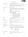
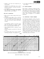
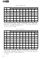
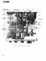
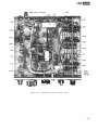
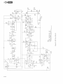
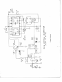
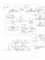
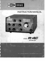
TABLE OF CONTENTS
CHAPTER I
INTRODUCTION
l-l.
GENERAL DESCRIPTION
.
.
.
.
.
.
.
.
.
.
.
.
1-2.
MANUAL COVERAGE
.
.
.
.
.
.
.
.
.
.
.
.
.
.
.
.
.
.
.
.
.
.
.
.
.
.
.
SPECIFICATIONS
CHAPTER II
.
INSTALLATION.
.
.
.
.
.
.
.
.
.
.
.
.
.
.
.
.
.
.
.
.
.
.
.
.
.
.
.
.
.
.
.
.
l-l
.
.
.
.
.
l-l
.
.
.
.- .
l-3
.
2-l
.
.
.
.
UNPACKING .
.
.
.
.
.
.
.
.
.
2-2.
LOCATION
.
.
.
.
.
.
.
.
.
.
.
.
.
.
.
.
.
.
.
.
.
.
.
.
.
2-3.
POWER REQUIREMENTS
.
.
.
.
.
.
.
.
.
.
.
.
.
.
.
.
.
.
.
.
.
2-l
2-4.
GROUND
2-5.
.
.
.
.
.
.
.
.
.
.
.
.
.
2-l
2-l
.
.
.
.
.
.
.
.
.
.
.
.
.
.
.
.
.
.
.
.
.
.
.
.
.
.
2-l
ANTENNA.
.
.
.
.
.
.
.
.
.
.
.
.
.
.
.
.
.
.
.
.
.
.
.
.
.
.
2-l
2-6.
M U T E . .
.
.
.
.
.
.
.
.
.
.
.
.
.
.
.
.
.
.
.
.
.
.
.
.
.
.
2-2
2-7.
ANTI VOX.
.
.
.
.
.
.
.
.
.
.
.
.
.
.
.
.
.
.
.
.
.
.
.
.
.
.
2-2
2-8.
INJECTION
.
.
.
.
.
.
.
.
.
.
.
.
.
.
.
.
.
.
.
.
.
.
.
.
.
.
2-2
2-9.
CARRIER OSCILLATOR.
.
.
.
.
.
.
.
.
.
.
.
.
.
.
.
.
.
.
.
.
.
2-2
2-10.
PTO LAMP.
.
.
.
.
.
.
.
.
.
.
.
.
.
.
.
.
.
.
.
.
.
.
.
.
.
.
2-2
2-11.
SPEAKER .
.
.
.
.
.
.
.
.
.
.
.
.
.
.
.
.
.
.
.
.
.
.
.
.
.
.
2-2
2-12.
ACCESSORY POWER .
.
.
.
.
.
.
.
.
.
.
.
.
.
.
.
.
.
.
.
.
.
.
2-2
2-13.
ACCESSORY CRYSTAL FILTER INSTALLATION .
.
.
.
.
.
.
.
.
.
.
.
.
2-2
2-14.
ACCESSORY CRYSTALS.
.
.
.
.
.
.
.
.
.
.
.
.
.
.
.
.
.
.
.
.
.
2-2
2-15.
NOISE BLANKER
.
.
.
.
.
.
.
.
.
.
.
.
.
.
.
.
.
.
.
.
.
2-3
2-16.
CONNECTION TO T-4XC TRANSMITTER
.
.
.
.
.
.
.
.
.
.
.
.
.
.
.
2-3
2-17.
CONNECTION TO T-4/T-4X/T-4B/T-4XB TRANSMITTERS.
.
.
.
.
.
.
.
.
2-3
2-18.
CONNECTION TO TR-4 OR TR-4C.
.
.
.
.
.
.
.
.
2-3
-. . . . . . . . . . . . . . . . . . .
3-l
OPERATION
.
.
.
.
.
.
.
.
.
.
.
.
.
.
.
.
.
.
3-l.
GENERAL.
.
.
.
.
.
.
.
.
.
.
.
.
.
.
.
.
.
.
.
.
.
.
.
.
.
.
3-l
3-2.
FUNCTION
.
.
.
.
.
.
.
.
.
.
.
.
.
.
.
.
.
.
.
.
.
.
.
.
.
.
3-l
3-3.
M O D E . .
.
.
.
.
.
.
.
.
.
.
.
.
.
.
.
.
.
.
.
.
.
.
.
.
.
.
3-l
3-4.
MAIN TUNING DIAL .
.
.
.
.
.
.
.
.
.
.
.
.
.
.
.
.
.
.
.
.
.
.
3-l
3-5.
DIAL CALIBRATION .
.
.
.
.
.
.
.
.
.
.
.
.
.
.
.
.
.
.
.
.
.
.
3-l
.
.
.
.
.
.
.
.
.
.
.
.
.
.
.
.
.
.
.
.
3-3
FRONT PANEL CONTROLS
1976
.
.
l-l
2-l.
CHAPTER III
APRIL
Page
. . . . . . . . . . . . . . . . . . . . . . .
3-6.
XTALS .
.
.
.
.
.
.
.
.
.
.
.
.
.
.
.
.
.
.
.
.
.
.
.
.
.
.
.
3-4
3-7.
B A N D . .
.
.
.
.
.
.
.
.
.
.
.
.
.
.
.
.
.
.
.
.
.
.
.
.
.
.
3-4
3-8.
PRESELECTOR .
.
.
.
.
.
.
.
.
.
.
.
.
.
.
.
.
.
.
.
.
.
.
.
.
3-4
3-9.
PASSBAND TUNING
.
.
.
.
.
.
.
.
.
.
.
.
.
.
.
.
.
.
.
.
.
.
.
3-4
3-10.
GAIN .
.
.
.
.
.
.
.
.
.
.
.
.
.
.
.
.
.
.
.
.
.
.
.
.
.
.
.
.
3-4
3-11.
AGC .
.
.
.
.
.
.
.
.
.
.
.
.
.
.
.
.
.
.
.
.
.
.
.
.
.
.
.
.
3-5
3-12.
NOTCH.
.
.
.
.
.
.
.
.
.
.
.
.
.
.
.
.
.
.
.
.
.
.
.
.
.
.
.
3-5
TABLE OF CONTENTS (continued)
Page
3 5
. .
3-13.
S'METER
3-14.
PHONE-JACK.
3-15.
S'METER ZERO.
3-16.
B A S I C CONTROL SETTINGS
.
.
.
3 5
.
3 5
3- 5
3 - 17.
SSB RECEPTION
3-18.
CW RECEPTION
3-19.
AM RECEPTION.
3-20.
RTTY RECEPTION
3-21.
NOISE BLANKER
3-22.
A D D I T I O N A L TUNING RANGES
3-7
THEORY
OPERATION.
441
CHAPTER IV
.
.
3 -6
.
.
3-6
.
.
3 -7
.
OF
336
.
3-7
4-l.
GENERAL
.
441
4-2.
RF AMPLIFIER
.
4-l
4-3.
PREMIXER
. .
4 -1
4-4.
FIRST MIXER
4-l
4-5.
FIRST IF
4- 1
4-6.
SECOND IF SYSTEM AND DETECTORS
4-2
4-7.
AGC CIRCUIT.
4-2
4-8.
S METER
4-9.
AUDIO AMPLIFIER
4-10.
POWER SUPPLY.
4-11.
CRYSTAL CALIBRATOR . . . . . .
CHAPTER V
SYSTEM
.
.
.
.
.
.
.
.
.
.
.
.
.
.
MAINTENANCE
.
.
.
.
4-2
.
4-2
.
4-2
4-2
.
.
5-l
. . . . . . . .
5-l
. . . .
5-1
. . . . .
5- 1
. .
5-l
. . . . . . . .
5-l
. . .
5 1
5-l.
SERVICE DATA.
5-2.
MAINTENANCE.
5-3.
COVER REMOVAL.
5-4.
TEST EQUIPMENT REQUIRED
5-5.
TROUBLESHOOTING
5-6.
ALIGNMENT INSTRUCTIONS.
5-7.
50kHz BFO AND IF ALIGNMENT
5-2
5-8.
5645 OSCILLATOR ADJUSTMENT
5-2
5-2
5-9.
FILTER
5-10.
NOTCH FILTER ADJUSTMENT
MATCH
ALIGNMENT.
5-2
5-11.
5595 OSCILLATOR ADJUSTMENT
5 2
5-12.
ANTENNA, RF AND INJECTION ALIGNMENT
5-2
5-13.
S METER ADJUSTMENT.
5 3
5-14.
CRYSTAL CALIBRATOR ADJUSTMENT
5 3
LIST OF ILLUSTRATIONS
Figure
1-1.
R-4C RECEIVER
2-1.
VIEWING
2-2.
REAR
2-3.
CONNECTING
3-1.
FRONT
.
.
.
.
.
.
OPTIONS.
.
.
.
.
.
.
2-m 5
.
.
2-5
.
.
2-3
.
.
3-2
3-2.
PRESELECTOR TUNING RANGES . . . . .
3- 7
3-3.
AM SELECTIVITY CURVES. . . . . . . .
3 8
3-4.
SSB AND CW SELECTIVITY CURVES . . . .
339
4-1.
BLOCK
.
443
5-l.
A L I G N M E N T LOCATIONS,TOP VIEW . . .
557
5-2.
ALIGNMENT LOCATIONS, BOTTOM VIEW . .
5-8
ACCESSORY NOISE BLANKER MODEL 4-NB .
5-8
SCHEMATIC
5 --9
ANGLE
CHASSIS
.
CONTROLS
THE
PANEL
.
Page
1 2
.
5-3.
.
.
TR--4C.
.
CONTROLS.
DIAGRAM
.
DIAGRAM
.
.
.
.
.
.
.
.
.
.
.
.
.
.
.
.
.
.
.
.
.
.
.
.
.
.
.
.
.
...
III
CHAPTER I
INTRODUCTION
1.1. GENERAL DESCRIPTION.
the frequency range of the receiver.
The R-4C Receiver is a triple conversion superheterodyne receiver designed for optimum reception of all types of amateur radio communications.
It provides complete coverage of the 80, 40, 20,
and 15 meter amateur bands and 28.5 to 29.0 MHz
of the 10 meter band with the crystals supplied.
Additional/ coverage of 500 kHz segments between
1.5 and 30 MHz is possible with the addition of
accessory range crystals. Sockets are provided for
up to 15 additional crystals. A highly linear
permeability-tuned solid state VFO and premixed
injection give excellent stability and dial calibration
on all bands. Eight pole crystal filter selectivity
combined with passband tuning and a tunable
notch filter provide superior interference rejection.
Three AGC time constants are selectable from the
front panel and a 25 kHz crystal calibrator provides
convenient markers at 25 kHz intervals throughout
1-2. MANUAL COVERAGE.
-
This manual is presented in 5 chapters and is arranged for the convenience of the operator and
service technician as follows:
Chapter I
Introduction (self explanatory).
Chapter II
Installation. Describes the procedures
to be followed prior to operation.
Chapter III
Operation. Illustrates and describes
front panel controls and describes
operation in SSB, CW and AM modes.
Chapter IV
Theory of Operation. Describes all
critical circuits and networks.
Chapter V
Maintenance. Provides maintenance
instructions and parts ordering information.
1.1
SPECIFICATIONS
Frequency Coverage :
Covers 3.5 to 4.0 MHz, 7.0 to 7.5 MHz, 14.0 to 14.5 MHz, 21.0 to
21.5 MHz, and 28.5 to 29.0 MHz.
Accessory Coverage:
15 accessory crystal sockets are provided. Coverage of any additional
500 kHz ranges between 1.5 and 30 MHz (except between 5.0 and
6.0 MHz) can be added by installing accessory crystals.
Modes of Operation:
SSB, CW, AM, RTTY.
Sensitivity:
SSB Mode: 10 dB signal-plus-noise to noise ratio obtained on 80 M10 M amateur bands with less than a 0.25 microvolt signal on the
antenna terminal, on other frequencies less than 0.5 microvolt signal.
Selectivity:
As supplied:
SSB Mode: 2.4 kHz at 6 dB, 4.2 kHz at 60 dB.
AM Mode: 8.0 kHz at 6 dB, 28 kHz at 60 dB.
With accessory crystal filters:
AM Mode, 2 filters available:
6.0 kHz at 6 dB, 10 kHz at 60 dB.
4.0 kHz at 6 dB, 7.5 kHz at 60 dB.
CW 1.5, CW .5, CW .255 Modes, 3 filters available:
1.5 kHz at 6 dB, 3.0 kHz at 60 dB.
500 Hz at 6 dB, 1000 Hz at 60 dB.
250 Hz at 6 dB, 600 Hz at 60 dB.
Stability :
After warm up, frequency will not drift more than +- 100 Hz, including voltage variation of +- 10%.
Calibration:
Better than +- 1 kHz when calibrated at nearest 100 kHz calibration
point.
Spurious Responses:
Internal spurious response less than the equivalent of a 1 microvolt
antenna signal on all amateur bands.
Image Rejection:
(11.29 MHz above desired): Over 70 dB below 23 MHz, 60 dB above
23 MHz.
Input Impedance:
52 Ohms nominal.
Audio Output Impedance:
3.2 Ohms to speaker, or headphones, 3000 Ohms anti
Audio Output:
0.7 Watt at AVC threshold, 2 Watts maximum at less than 5% T.H.D.
AGC:
Audio Output increases 3 dB maximum for a RF input increase of
100 dB above AGC threshold. AGC threshold typically 1 microvolt.
Attack time:
1 millisecond
Release times:
Slow:
1 second
Medium: 350 mSec
Fast:
50 mSec
VOX.
Power Consumption:
60 Watts, 120/240 Volts AC, 50/60 Hz.
Size:
5.5 inches high, 10.75 inches wide, 12.25 inches deep overall.
Weight:
17 pounds.
1-3
CHAPTER II
INSTALLATION
2-1. UNPACKING.
Carefully remove the receiver from the shipping
carton and examine it for evidence of damage. If
any damage is discovered, immediately notify the
transportation company that delivered the receiver.
Be sure to keep the shipping carton and packing
material, as the transportation company will want
to examine them if there is a damage claim. Keeping the carton and packing is recommended in any
case, as having these available makes packing the
receiver much easier should it ever be necessary to
store it or return it to the factory for service.
Inspect the packing material before putting it away
to be sure you have not overlooked any accessory
hardware. The hardware consists of two studs,
No. l0-24,5/8 inch long, and two small rubber feet.
Examine your R-4C to make sure that all tubes
and crystals are properly seated in their sockets.
NOTE
Fill out the enclosed registration card
and return it to the factory immediately
to insure registration and validation of
the warranty.
2-2. LOCATION.
The location of the R-4C is not critical, as long as
allowance is made for adequate air circulation.
Avoid extremely hot locations. It is recommended
that a minimum clearance of one inch be maintained at each side of the R-4C. Do not cover the
top with books, paper, or pieces of equipment.
With the studs and rubber feet supplied, it is possible to position the R-4C for either of two alternate viewing angles, as shown in figure 2-l. To convert the R-4C to either option, the first step is to
remove the bottom cover from the receiver. Remove the bottom row of three screws on each side
of the receiver, and the cover can be removed.
Remove the rear feet, and snap the small rubber
feet into the holes just outboard from the original
rear feet. For option B, put the bottom cover back
on the receiver. For option C, remove the front
feet from the receiver, invert them, and remount
them on the same screws. Then thread one of the
accessory studs into each of the remounted front
feet. Finally, mount the feet that were removed
from the rear of the receiver on the studs, and put
the bottom cover back onto the receiver.
2-3. POWER REQUIREMENTS.
CAUTION
Operation of this receiver with the wrong
power source may result in serious damage.
Refer to figure 2-2. As shipped from the factory
the R-4C is wired for 120 Volt 50/60 Hz AC
operation. The receiver may also be operated from
240 V AC by removing the retaining tab and placing the 120/240 Volt slide switch on the rear panel
in the 240 Volt position. Replace the retaining tab
on the opposite mounting screw to prevent the
switch from accidentally being returned to the
120 V position. Operation of the receiver from
240 V with the switch in the 120 V position will
cause serious damage.
2-4. GROUND.
A screw terminal is provided on the rear panel for
connection to the station ground. Also, if used with
the T-4XC transmitter and other accessories, connect a ground strap between the ground terminals
of all units.
2-5. ANTENNA.
The jack labeled ANT is the connection point for
the antenna. The nominal impedance of the circuit
is 52 Ohms.
2-1
2-6. MUTE.
2-11. SPEAKER.
The MUTE jack provides connections for external
standby-receive switching. The external circuit must
isolate the MUTE jack center conductor from
ground for standby, and connect it to the MUTE
jack ground for receive. The R-4C is shipped with
a shorted phono plug in this jack. When used with
a transmitter, remove the shorted plug and connect
the appropriate cable to the transmitter MUTE
jack.
The audio output from the receiver is available at
the jack marked SPKR. The output impedance is
3.2 Ohms.
2-7. ANTI VOX.
High impedance audio is available at the ANTI
VOX jack for use with the anti VOX circuit of the
transmitter.
2-8. INJECTION.
The phono jack marked INJ. provides a means of
coupling the premixer system of the R-4C to the
D r a k e T - 4 , T-4B, T-4C, T - 4 X , T - 4 X B o r
T-4XC transmitters for transceive operation.
2-9. CARRIER OSCILLATOR.
The jack marked CAR. OSC provides a means of
coupling injection from the T-4XC carrier oscillator to the R-4C receiver. This connection phaselocks the two units to exactly the same frequency
when used in the SSB Transceive mode. No connection is made to this jack for use with the T-4X or
T-4XB transmitter.
2-10. PTO LAMP.
This jack provides a ground return for the pilot
lamp behind the PTO dial. The R-4C is shipped
with a shorted phono plug in this jack so that the
lamp will light. When the R-4C is used with the
T-4XC transmitter, remove the shorted phono
plug and connect a cable between the PTO lamp
jacks of the two units. The lamp will then light
only when the T-4XC TRANSCEIVE switch is in
the RCVR, SEPARATE, or SPOT positions. In the
XMTR position, the lamp will not light to indicate
that the R-4C PTO is disabled.
2-2
2-12. ACCESSORY POWER.
The accessory power socket, labeled ACCY POWER,
located on the rear of the chassis, provides power
for operating accessories. Maximum load is 6.3
Volts AC at 300 milliamperes and 12 Volts DC at
50 milliamperes. A connection to the antenna is
also available. The socket mates with a Cinch type
5AB2 plug.
2-13. ACCESSORY CRYSTAL FILTER
INSTALLATION.
To install additional crystal filter(s), proceed as
follows: Remove the two screws holding the filter
cover bracket for each position in which a filter is
being installed. The upper position is for the .250
kHz filter, the center position is for the .500 kHz
filter, and the lower position is for the 1.5 kHz
filter. If a filter for the AM mode is being installed,
remove the top cover of the R-4C, the mode
switch cover and remove the filter cover bracket
and the 150 Ohm jumper resistor from the AM
filter socket. Very carefully plug each filter straight
into the sockets.
After installing all the filters desired, replace the
cover brackets over each filter and tighten the
mounting screws. Do not attempt to use accessory
filters without installing the brackets as it is very
important to have a solid ground connection between the bottom of the filter and the spring
material.
2-14. ACCESSORY CRYSTALS.
By inserting the appropriate crystals in the accessory crystal sockets at the top rear of the chassis, it
is possible to add up to 15 additional tuning ranges
(each 500 kHz wide) to the coverage of the R-4C.
With the exception of the band from 5.0 to 6.0
MHz, these additional ranges may be anywhere between 1.5 and 30 MHz. Only series resonant crystals
should be used for accessory coverage. Selected
crystals for accessory coverage with the R-4C will
be supplied by the R. L. Drake Company at a nominal cost. Contact Customer Service Department at
the address given in paragraph 5-l for price and
delivery information. To determine the correct
crystal frequency for any additional range, see
table 2-l which shows the required crystal frequency and the proper BAND switch setting for the
R-4C for the frequency spectrum from 1.5 to 30
MHz, except for the 5.0 to 6.0 MHz range. However, if you are going to transceive with the Drake
T - 4 , T-4B, T-4C, T - 4 X , T-4XB, or T-4XC,
the crystal selection table in the transmitter manual
should be followed in selecting accessory crystals.
Remove the screws holding the shield/cover over
the 15 accessory crystal sockets on the rear panel.
Install the desired crystals and replace the cover
and its mounting screws.
Turn on the receiver and tune in the crystal calibrator signal. Detune the PRESELECTOR until
calibrator signal S meter reading is around S5.
Temporarily unplug the 4-NB cable and reinstall
the jumper plug. Compare S meter readings. If the
gain varies more than l/2 S unit between the 4-NB
and the jumper plug, adjust R12 (blue potentiometer on 4-NB) until S meter readings are equal
when switching between the 4-NB and the jumper
plug. Replace cabinet top.
2-16. CONNECTION TO T-4XC
TRANSMITTER.
For interconnection diagram see the T-4XC instruction manual.
2-17. CONNECTION TO T-4/T-4X/T-4B/
T-4XB TRANSMITTERS.
2-15. NOISE BLANKER.
To install the optional 4-NB Noise Blanker, remove the top row of three screws on each side of
the R-4C. Remove the cabinet top. Remove the
jumper plug from the noise blanker socket which is
located toward the rear of the receiver, on top of
the chassis. Retain the jumper plug so that it may
be used if the 4-NB should ever require service.
The 4-NB mounts on the four plastic stand-offs
which are on the metal shields on either side of the
PTO. Align the plastic stand-offs with the four
holes in the 4-NB circuit board with the 4-NB
cable toward the rear of the R-4C. Carefully push
the 4-NB onto the stand-offs until it snaps into
place. Dress the 4-NB cable toward the rear of the
receiver and through the notch in the filter shield
just above the NB socket and under the mode
switch cover. Plug the 4-NB into the NB socket
of the R-4C.
Connect as indicated in the transmitter instruction
manual. No connection will be made to the CAR
OSC jack and the shorted phono plug should be
left in the PTO LAMP jack. Follow the instructions
in the transmitter manual for Transceive Alignment
if necessary. When making the adjustment, set the
R-4C PASSBAND TUNING at 12 o’clock and the
MODE Switch to SSB. Other control settings are
the same as stated for the R-4/R-4B. The adjustment on the R-4C is C59 located on a PC board on
the top of the R-4C chassis (see figure 5-l). Adjust
this capacitor for zero canary chirps.
2-18. CONNECTION TO TR-4 OR TR-4C.
To use the R-4C as an external receiver with the
TR-4/TR-4C transceiver, make the connections
illustrated in figure 2-3.
2-3
Table 2- 1.
FREQUENCY
RANGE
CRYSTAL
1.5
2
2
2
--2.0
CRYSTAL
BAND
1.5 - 3.0
16.5 - 1 17.0
27.6
21.0
13.1
1.5 - 3.0
17.0 - 17.5
28.1
21.0
2.5 - 3.0
13.6
1.5 - 3.0
17.5
- -
28.6
3.0 - 3.5
14.1
3.5
18.0 - 1 8.5
3.5 - 4 .0
14.6*
3.5
18.5 - 1 9.0
29.6
21.0
4.0 - 4 . 5-
15.1
3.5
19.0 - 19.5
30.1
21.0
4.5 - 5 .0
15.6
3.5
19.5 - 20.0
30.6
21.0
6.0 - 6 .5
17.1
7.0
20.0 - 20.5
31.1
21.0
6.5 - 7.0
17.6
7.0
20.5 - 2 1.0
31.6
21.0
7.0 - 7.5
1 18.1*
7.0
21.0- - 21.5
32.1*
21.0
7.5 - 8 .0
18.6
7.0
21.5 - 2 2.0
32.6
21.0
8.0 -
8.5
19.1
7.0
22.0 - 22.5
33.1
21.0
8.5 -
9.0
19.6
7.0
22.5 - 23.0
33.6
21.0
9.0 - 9.5
20.1
7.0
23.0 - 2 3.5
34.1
28.5
9.5 - 10.0
20.6
7.0
23.5 - 24.0
34.6
28.5
2.5
- 1 0.5
10.0 -
-
21.1 @
14.0
18.0
-
21.0
21.0
24.0 - 24.5
28.5
10.5 - 11.0
21.6
14.0
24.5 - 25.0
35.6
28.5
11 .o - 11.5
22.1
14.0
25.0 - 2 5.5
36.1
28.5
1 1.5 - 12.0
22.6
14.0
25.5 - 26.0
36.6
28.5
12.0 - 1 2.5
23.1
14.0
26.0 - 26.5
37.1
28.5
12.5 - 13.0
23.6
14.0
26.5 - 27.0
37.6
28.5
13.0 - 13.5
24.1
14.0
27.0 - 27.5
38.1
13.5 - 14.0
24.6
14.0
27.5 - 28.0
38.6
28.5
14.0 - 14.5
225.1*
14.0
28.0 - 28.5
339.1
28.5
14.5 - 15.0
25.6
14.0
15.0 - 1 5.5
26.1 @
14.0
29.0 - 29.5
29.5 - 30.0
15.5 - 1 6.0
26.6
14.0
16.0 - 16.5
27.1
21.0
*Supplied with receiver
2-4
FREQUENCY
RANGE
BAND
c 12.6
2.0 -
I
Crystal Frequency Chart
.
28.5 - 29.0
_
-
39.6*
0 40.1
40.6 m
28.5
28.5
28.5
28.5
o
CHAPTER III
OPERATION
3-1. GENERAL.
Figure 3-l illustrates and describes the front panel
controls. Refer to the text in this chapter for detailed operating instructions. Rear chassis connectors are identified in figure 2-2.
3-2. FUNCTION.
With the FUNCTION switch in the OFF position,
the primary of the power transformer is disconnected from the line cord. In the standby (STBY)
position all operating voltages are applied to the
receiver circuits, but the receiver is muted. With the
switch in the ON position, the receiver operates
unmuted regardless of external muting connections.
The EXT. MUTE position is the same as the ON
position, except that receiver muting is externally
controlled through the MUTE jack on the rear of
the chassis. Switching to the NB position energizes
the accessory Noise Blanker, when it has been installed, without changing the muting function.
Switching to the CAL position energizes the 25
kHz Crystal calibrator without changing the muting
function. If external muting is not used, the shorting plug (supplied with the R-4C) must be inserted
into the Mute jack in order to obtain NB and CAL
operation.
Tuning is inoperative in AM mode. In the SSB
mode, the product detector is used. The 2.4 kHz,
8 pole crystal filter which is mounted internally
determines the selectivity. This mode is used for
normal SSB reception and can also be used for CW
and RTTY.
In the CW 1.5, CW .5 and CW .25 modes, the
product detector is used. Selectivity is determined
by the accessory filter(s) which are installed in the
sockets on the rear panel. The passband tuning is
operative in the SSB and the three CW modes. Note
that the receiver will not operate in the CW 1.5,
CW .5, or CW .25 mode until a filter is installed in
the appropriate rear panel socket.
3-4. MAIN TUNING DIAL.
This dial has 2 transparent discs which display concentric scales and which rotate at different speeds.
Zero to 100 kHz is indicated on one disc and hundreds of kHz is indicated on the other. The frequency of the operating signal is the sum of the
frequencies indicated by the BAND switch and the
Main Tuning Dial, for example:
3-3. M O D E .
The MODE switch determines the desired selectivity and selects the proper detectors. In the A M
position, the AM detector is switched in. The I F
bandpass of the receiver is 8 kHz as determined by
the 4 pole 1st IF crystal filter and the two 50 kHz
tuned circuits. For additional selectivity an accessory AM 8 pole filter can be installed in the internal
accessory filter socket in place of the 150 Ohm
resistor which is supplied. The selectivity then has
8 pole response in the AM mode. The Passband
BAND switch setting
100 kHz dial
1 kHz dial
7.000 MHz
.200 MHz
.026 MHz
Received frequency
7.226 MHz
3-5. DIAL CALIBRATION.
.
The Main Tuning Dial may be calibrated by the
following procedure:
a. Set the FUNCTION switch to CAL and set the
PASSBAND TUNING control to 12 o’clock.
b. Tune the R-4C to zero beat with the nearest
25 kHz calibrator signal.
C.
Hold the knob on the Main Tuning control
3-1
FRONT PANEL CONTROLS
1. S Meter: Indicates relative signal strength.
Calibrated in S units from 1 to 9. Above 9 the
scale is calibrated in decibels.
8. PASSBAND TUNING Control: Adjusts the
positioning of the BFO in SSB and CW modes.
2. FUNCTION Switch: Selects standby, external
mute and crystal calibrator functions and
switches in the Model 4-NB Noise Blanker.
Also turns the Receiver on and off.
9. Phone Jack: Provides a connection for headphones.
3. MODE Switch: Selects Receiver operating
mode.
4. Main Tuning Dial: Displays a portion of the
received frequency from zero to 500 kHz. The
reading must be added to the BAND switch
setting to determine the exact frequency.
5. Main Tuning Control: Adjusts frequency setting of the Main Tuning Dial.
6. AGC Switch: Selects the release time constant
of the automatic gain control circuit (slow: S;
medium: M; fast: F) or turns off the AGC.
10. PRESE LECTOR Control: Tunes the antenna,
RF and premixer coupling coils.
11. GAIN Control: Knob adjusts AF gain. Lever
controls RF gain (normally in full clockwise
position).
12. XTALS Switch: Selects accessory crystals for
accessory band operation ( 15 positions). NORM
position transfers crystal selection function to
BAND switch for amateur band operation.
13. BAND Switch: Selects amateur band desired
when XTALS switch is in NORM position.
Also selects proper RF circuits for accessory
crystal operation (refer to table 2-l for correct
setting).
7. NOTCH Control: Attenuates heterodyne interference in all modes of reception.
3-3
stationary and rotate the knob skirt until the
dial displays the correct frequency.
3-6. X T A L S .
In the NORM setting of this 16 position switch, the
proper crystal for reception of the various amateur
bands is selected by the BAND switch (except at
the 1 .5 setting). The numbered positions of this
switch correspond to the accessory crystal sockets
mounted at the rear of the receiver. When the
switch is set to a numbered position, the crystals in
the socket having the same number will be connected to the circuit for accessory band operation.
(The range window, just to the right of the XTALS
control, provides a convenient place to write in the
frequency covered in each accessory band). The
band switch must then be operated in accordance
with table 2-l .
3-7. B A N D .
This six position switch selects the amateur band
desired during normal operation. It also is used to
select the proper RF circuits for the various tuning
ranges when use is made of accessory crystals for
other frequency ranges. Correct setting of the
BAND switch during accessory operation is shown
in table 2-1.
3-8. PRESELECTOR.
Rotation of this control changes the tuning of the
antenna, RF, and premixer coupling coils. The
outer ring of numbers, around the base of this control indicates the general setting for the various
bands. Fine adjustment for peak reception is made
after the signal is tuned in. A scale calibrated from
0 through 10 is provided for logging. See figure 3-2
for setting for out-of-amateur-band operation.
3-9. PASSBAND TUNING.
The PASSBAND TUNING control adjusts the positioning of the BFO with respect to the receiver
passband but without changing the frequency to
which the receiver is tuned. This control operates
in the SSB, CW 1 .5 CW .5 CW .25 modes. The
curved lines above the knob indicate the relative
bandwidths and positions of the passbands. The
3-4
knob pointer indicates the position of the BFO
with respect to the passband. The longest line indicates the passband width of the 2.4 kHz filter
used in the SSB mode. The dot at the left end of
this line shows the normal setting of the BFO with
respect to the passband for LSB reception. The dot
at the right end of this line shows the normal positioning of the BFO for USB reception. However, to
emphasize lower audio frequencies and reduce high
pitched interference, the control may be adjusted
slightly closer to the passband (toward 12 o’clock
position). Conversely, to emphasize higher frequencies the PASSBAND TUNING control may bc set
to position the BFO slightly farther away from the
passband than the dot indicates. Note that because
the received frequency is not changed when the
PASSBAND TUNING control is moved, selection of
USB or LSB with this control is possible with n o
retuning of the PTO to keep the receiver tuned to
the same carrier frequency. Careful adjustment of
this control c a n result in markedly improved reception under heavy interference conditions. When the
1 .5 kHz crystal filter has been installed in
the CW 1.5 mode, the second longest line indicates the relative width and position of this filter
passband. Again the PASSBAND TUNING knob
shows the position of the BFO with respect to this
passband. When the 500 Hz or 250 Hz filter has
been installed in the CW .5 or CW .25 position,
the shortest line above the *PASSBAND TUNING
knob is used. When tuning in a CW signal, the received signal will be centered in the passband. The
BFO frequency (as indicated by the relative position of the PASSBAND TUNING) must be offset
by the amount needed to produce the desired beat
frequency. Normally the correct setting will be just
beyond either the left or right end of the line corresponding to the bandwidth of the filter in use.
For higher beat note frequencies, the knob must be
moved farther beyond the end of the passband line.
For RTTY reception of 2125 and 2975 tone frequencies, the PASSBAND TUNING control should
be in the RTTY area.
3-10. GAIN.
The GAIN control consists of two concentric controls. The inner control is the AF Gain and is adjusted with the knob. The AF Gain control varies
the audio output from the receiver by varying the
audio voltage applied to the audio amplifier stages.
The outer control which is adjusted with the lever
is the RF Gain control. This control increases the
AGC threshold or bias level on the RF and IF stages
which prevents signals below a certain level from
being received. Normally this control should remain
in the full clockwise position.
3-11. A G C .
3-13. S METER.
The S Meter indicates relative signal strength, and is
a convenient indicator for peaking the tuning of
the receiver. The lower (left hand) portion is calibrated in S units from S-l through S-9. Above S-9
the scale is calibrated in decibels. Each S unit is
equal to approximately 5 dB. An S-9 signal is approximately 30 microvolts input to the antenna
Jack.
This switch selects the release time constant of the
automatic gain control circuit or turns off the AGC.
In the OFF position, the receiver gain may be controlled manually with the RF gain control. In the
F (fast release). M (medium release), or S (slow release) positions, the AGC is operative. The release
time constant is approximately 1 second in the S
position, 350 milliseconds in the M position, and
50 milliseconds in the F position. Attack time is 1
millisecond in F, M, S modes.
3-12. N O T C H .
The NOTCH control can be used effectively in all
modes of reception for attenuation of heterodyne
interference from a carrier near the desired carrier.
A permeability-tuned T-notch filter in the 50 kHz
IF is used for this purpose. The filter produces a
deep notch which can be tuned across the IF by
rotation of the NOTCH control knob. On any mode
of operation, an unwanted carrier is attenuated by
tuning the notch across the receiver passband until
the unwanted carrier is removed by the notch filter.
Since the notch filter will remove the wanted carrier just as readily as an unwanted carrier, the
NOTCH control must be adjusted carefully for
maximum effectiveness. In the SSB, CW 1.5, CW -5,
or CW .25 modes, the PASSBAND TUNING will also affect the NOTCH frequency. Therefore, the
PASSBAND TUNING control should be set before
the NOTCH control is adjusted. However, after obtaining a notch, the PASSBAND TUNING may be
moved slightly to fine tune the notch for maximum null. When a notch is not needed, the NOTCH
control should be returned to the detent in the
OFF position.
3-14. PHONE JACK.
The phone jack is used when private listening is
desired. Connection of the headphones automatically mutes the speaker output. While headphone
impedance is not critical, a good quality set of 600
Ohm phones will work well. If 8 Ohm headphones
are used, a pad should be connected between the
phone jack and the phones to reduce the audio
power to a reasonable level for the phones. Normally connecting a 100 Ohm resistor in series with the
8 Ohm headphones will provide adequate attenuation.
3-15. S METER ZERO.
NOTE
The antenna should be disconnected from
the R---4C while making this adjustment.
The S meter zero control is on the rear panel of the
R-4C. It may be used to set the S meter needle to
S-l under no-signal conditions.
3-16. BASIC CONTROL SETTINGS.
For operation in any mode, preset the following
controls as indicated:
a. Set FUNCTION switch to ON.
b. Set BAND switch to Desired Amateur Band.
c. Set XTALS switch to NORM.
d. Set NOTCH control to OFF.
e. Set RF GAIN lever fully clockwise.
3-5
3-18 CW RECEPTION.
f. Set AF GAIN knob to a comfortable level.
g. Set PRESELECTOR control to center of band
segment marked on panel. After desired signal is
tuned in, adjust for maximum S meter reading.
3-17. SSB RECEPTION.
a. Make the basic control settings listed above.
b. Set MODE switch to SSB.
c. Set PASSBAND TUNING to the dot at either
the LSB or USB position as desired.
d. Set AGC switch to S.
e. Tune in station with Main Tuning knob.
f. Adjust PRESELECTOR for maximum S meter
reading.
After tuning in a station as described above, additional adjustments may be made to further improve
reception under various conditions or operator
preferences.
g. Normally the AGC time constant S is optimum
for SSB but for rapidly changing signal conditions, it may be desirable to switch to the AGC
release time constant M. The F or OFF positions
will not normally be desirable for SSB reception.
h. The PASSBAND TUNING control may be adjusted slightly away from the dot at the LSB or
USB position to emphasize low or high frequencies. The fine adjustment of this control is largely one of operator preference, and the setting
should be the one which produces the most
pleasing audio response or minimum interference.
Under extremely adverse interference conditions
the 1.5 kHz bandwidth crystal filter may be used
to advantage for SSB reception if this accessory
filter has been installed. Careful adjustment of
the PASSBAND TUNING control will aid in the
effective use of this restricted bandwidth for
SSB reception.
The NOTCH control may be used to attenuate
an interfering heterodyne. See paragraph 3-l 2
for adjustment of this control.
k. If impulse type noise interference is a problem,
the accessory 4-NB Noise Blanker may be
installed. The Noise Blanker may then be activated by placing the FUNCTION switch in the NB
position.
3-6
a. Make the basic control settings listed in paragraph 3-l6.
b. Set the MODE switch to SSB if the 2.4 kHz
bandwidth filter is desired. If one of the narrower bandwidth accessory crystal filters has been
installed it may be selected with the MODE
switch.
C.
Set the PASSBAND TUNING to the dot at LSB
or USB if the SSB mode is used. If the 1.5 kHz
accessory bandwidth is used, set this control just
beyond one end of the second longest line. If the
500 Hz or 250 Hz filter is used, set the PASSBAND TUNING just beyond one end of the
shortest line.
d. Set the AGC switch to S.
e. Tune in a CW signal with Main Tuning knob for
maximum S meter reading.
f. Adjust PRESELECTOR for maximum S meter
reading.
After tuning in a station as described above, additional adjustments may be made as follows:
If a different frequency beat note is desired, retune the MAIN TUNING for desired beat note
while keeping the signal peaked for maximum
strength with the PASSBAND TUNING control.
Faster AGC release time constants may be selected with the AGC control. If desired, the AGC
may be switched OFF and the gain controlled
manually with the RF GAIN lever.
The NOTCH control may be used to attenuate
interfering undesired heterodynes. See paragraph
3-l 2 for adjustments of this control.
The accessory 4-NB Noise Blanker may be used
if impulse noise interference is a problem.
3-19. AM RECEPTION.
Make the basic control settings listed in paragraph 3-16.
Set MODE switch to AM.
Tune in station for maximum S meter indication.
d. Peak PRESELECTOR for maximum signal
strength.
e. Medium or Fast AGC time constant may be
used if desired.
h. The 4-NB Noise Blanker may be used if it has
been installed.
f. Additionally, the NOTCH filter may be used if
necessary to attenuate interfering heterodynes.
See paragraph 3-l 2.
3-21. NOISE BLANKER.
This accessory is activated by placing the FUNCTION switch in the NB position. The Model 4-NB
Noise Blanker can be used on any type of reception.
It is most effective on short duration noise impulses
such as those generated by automotive ignition
systems. Refer to paragraph 2-l 5 for installation
instructions.
g. The 4-NB Noise Blanker may be used if impulse
noise interference is a problem. The 4-NB will
function on AM as well as SSB/CW.
3-20. RTTY RECEPTION.
a. Make the basic control settings listed in paragraph 3-l 6.
3-22. ADDITIONAL TUNING RANGES.
b. Set MODE switch to SSB; or, if the 1.5 kHz filter has been installed, this position may be used.
Also, if the 500 Hz filter has been installed, this
filter may be used for narrow shift RTTY
reception.
C.
By inserting the appropriate crystals in the accessory crystal sockets at the top rear of the chassis, it
is possible to add up to 15 additional tuning ranges
(each 500 kHz wide) to the coverage of the R-4C.
With the exception of the band from 5.0 to 6.0
MHz, these additional ranges may be anywhere
between 1.5 and 30 MHz. In order to receive with
an accessory crystal, the XTALswitch of the R-4C
must be set to the number corresponding to the
accessory crystal socket into which the crystal was
plugged. The lowest frequency of the accessory
range may then be marked in the range window for
reference. The marking is easily erased when crystals
are changed. Refer to figure 3-2 for the recommended tuning range for each band.
Set PASSBAND TUNING to the RTTY region.
Make fine adjustment for optimum reception.
d. Tune in station with MAIN TUNING knob.
e. Adjust PRESELECTOR for maximum S meter
indication.
f. It may be desirable to use the M or F AGC time
constant.
g. The NOTCH control may be used to attenuate
interferring heterodynes. See paragraph 3-l 2.
BAND
3.5
10
7.0
14.0
21.0 28.0
9
8
7
8
5
4
3
2
1
0
1.5
2
3
4
5
6
7
8
9
10
15
20
30
FREQUENCY (MC)
NOTE: SOLID LINE INDICATES RECOMMENDED RANGE FOR EACH BAND.
Figure 3-2. Preselector Tuning Ranges
3-7
CHAPTER IV
THEORY OF OPERATION
4-1. GENERAL.
Refer to the block diagram figure 4-l and the
schematic diagram figure 5-3 as required for the
following circuit descriptions.
4-2. RF AMPLIFIER.
Signals from the antenna are fed from Jl (ANT.)
to permeability-tuned transformer Tl , and are
applied to the grid of V1 through the tuned circuit
formed by Tl and capacitors Cl through Cl 2. The
amplified signal is coupled from the plate of VI to
the grid of V2 through the tuned circuit formed by
permeability-tuned coil T2 and capacitors Cl8
through C28.
4-3. PREMIXER.
The premixer system includes a transistorized permeability-tuned VFO, crystal-controlled oscillator
Q12, premixer tube V6, and the output circuitry
consisting of T3 and T4 and the associated tuning
and coupling capacitors. The PTO is tunable from
4955 kHz to 5455 kHz. The output of the PTO is
applied to the cathode of V6. The output of crystalcontrolled oscillator Q12 is applied to the grid of
V6. The crystal selected to control oscillator Q12
is determined by the settings of the XTALS and
BAND switches. The frequency of the crystal selected will always be such that the difference frequency obtained by heterodyning the output of the
PTO with the output of oscillator Q12 will be
5645 kHz higher in frequency than the desired
signal frequency.
4-4. FIRST MIXER.
The output of premixer V6 is coupled to the first
mixer V2 through the permeability-tuned premixer
output coils, T3 and T4, and their associated tuning
and coupling capacitors. Heterodyning of the premixer output and the RF amplifier output in V2
results in a difference frequency output of 5645
kHz from V2. Gang tuning of the RF coils Tl and
T2 and the premixer ouptut coils T3 and T4 is
used to maintain a fixed frequency relationship
among these variable circuit elements. The output
from V2 is applied to the input of a four pole
crystal lattice filter with a bandwidth of approximately 8 kHz.
4-5. FIRST IF SYSTEM.
The output of the crystal filter is applied to the
gate of Ql, the 5645 kHz IF amplifier. The amplified output of this stage is fed first through the
noise blanker, if it is used, and then to grid 1 of V3,
the 2nd mixer. Here the 5645 kHz IF signal is
mixed with the BFO. In the SSB, CW 1.5, CW .5 or
CW .25 modes the output of V3 is the sum of the
5645 kHz IF signal and the BFO or approximately
5695 kHz depending on the setting of the PASSBAND TUNING control. In the AM mode the BFO
is off and V3 functions as a buffer amplifier with
the output at 5645 kHz. The output of V3 is fed
through the MODE switch S2 to the appropriate 8
pole crystal filters. In the AM mode the 5645 kHz
IF signal may be fed through a filter or fed directly
to stage V4 depending on whether an accessory,
filter is installed in the AM filter p osition. In the
SSB, CW 1.5, CW .5, and CW .25 modes the signal
passes through the 8 pole crystal filter with a center
frequency of 5695 kHz. As the frequency of the
BFO Q5 is varied by C86, the PASSBAND TUNING control, the desired sideband or portion of the
5645 kHz IF signal is positioned within the passband of the 5695 crystal filter. The output of the
crystal filter is then applied to the grid of V4
through the MODE switch, S2. In V4, the 5695
kHz signal is mixed with a 5645 kHz oscillator in
the SSB, CW 1.5, CW .5 or CW .25 modes. In the
AM mode the 5645 kHz signal is mixed with a
5595 kHz oscillator. The output of V4 is tuned to
the difference frequency of 50 kHz by the IF transformer (T7C). The Q of T7C is changed by the
position of the MODE switch. In the CW .5 or
CW .25 position, the high Q tap is connected to
provide additional selectivity.
4-1
4-6. SECOND IF SYSTEM AND DETECTORS.
The 50 kHz signal from T7C is coupled to the grid
of V5 through the T-Notch filter T8 and its associated circuitry. V5 further amplifies the signal
before it reaches the detectors. The signal path
from IF transformer T10 is determined by MODE
switch S2. In the AM mode, the BFO Q5 is off.
Detection is accomplished by diode CR4 and the
resulting audio is amplified by Q6. In the SSB, CW
1.5, CW .5 or CW .25 modes the BFO is on. The
BFO and IF output both feed the product detector
consisting of diodes CR2 and CR3. The MODE
switch selects the audio output of either Q6 on AM
or the product detector on other modes and applies
the audio to the audio amplifier section.
4-7. AGC CIRCUIT.
The output of the 50 kHz IF amplifier V5 also is
applied to Q7, the AGC detector. Q7 is biased past
cutoff under no-signal conditions. As the amplitude
of the signal from V5 is increased, a point is reached
where Q7 begins to conduct during a portion of
each cycle resulting in a negative DC voltage being
developed across resistor R50. Depending on the
position of the AGC switch, a combination of capacitors C73, C74, and C76 will be charged by this
DC voltage. The release time of the AGC is determined by this capacitor combination and R50. ‘The
negative-going AGC voltage is applied to various
filtering and delay networks and then to the grids
of V1, V3 and V5. Counterclockwise rotation of
the RF GAIN control increases the negative bias on
the AGC controlled stages, limiting their gain. Isolation of the mute line from ground also allows the
AGC line to swing to approximately 40 Volts
negative, cutting off the three stages and muting
the receiver.
4-8. S METER.
The S Meter is connected across a bridge circuit
which has the plate of V5 as one arm of the bridge,
and the plates of V2 and V4 as the other arm of
the bridge. Increasing signal strength results in the
application of AVC voltage to the grid of V5 causing the plate current to decrease thus unbalancing
the bridge and causing the S Meter to deflect up
4-2
scale. Potentiometers R32 and R33 are used to set
the bridge balance point, determining the zero adjustment of the S Meter. The current characteristics
of the plate circuits of V2 and V4 are such that
line voltage variation does not affect the zero setting of the bridge circuit. The sensitivity of the S
Meter is determined by the setting of potentiometer
R36, which is in series with the S Meter.
4-9. AUDIO AMPLIFIER.
The audio amplifier consists of a direct coupled,
Class A, transformer output audio amplifier consisting of Q9, Ql0, Ql 1, T13 and other associated
parts. T13 has two secondary windings; one to
match a speaker or headphone output and a high
impedance winding for antivox voltage. The audio
gain is varied by R72, the AF GAIN control, at the
input of Q9. Negative feedback is used to reduce
distortion and increase stability of the amplifier.
4-10. POWER SUPPLY.
The power supply consists of transformer T14 and
the associated circuitry. CR8, CR9, Cl 63, R114,
and C 164 form a full-wave, center-tapped configuration to supply 150 Volts DC. CRlO, CR1 1 and
Cl 67 form another full-wave rectifier to provide 12
Volts DC for the solid state stages. Q2, Cl 66 and
R116 form a filter to reduce the ripple on the 12
Volt supply. Negative bias voltage is obtained from
half-wave rectifier CR7 and Cl 62.
4-11. CRYSTAL CALIBRATOR.
When the FUNCTION switch is turned to the calibrate position, a ground is supplied to the calibrator
circuitry. Q14 is a crystal controlled oscillator at
100 kHz. The output from Q14 is fed to CR1 6 and
Q15 which shape the waveform to trigger the first
J-K flip-flop in Ul . The 100 kHz is applied to the
clock input causing the flip-flop to change state
once every cycle of the input, thus dividing by two.
The output of the first flip-flop is applied to the
clock input of the second J-K flip-flop which again
divides by two. The output of this flip-flop is a 25
kHz square wave which is applied to the antenna of
the receiver through the coupling network.
CHAPTER V
MAINTENANCE
5-1. SERVICE DATA.
c. Remove the six bottom screws from the sides of
the R-4C.
We will check and align your receiver at the factory
for a nominal fee if it has not been tampered with.
Transportation charges are extra. Any necessary
repairs will be made on a time and material basis.
Please write or call the factory for authorization
before returning your receiver for alignment or
service. Address your request for authorization to:
d. Lift the R-4C chassis out of the-bottom cover.
R. L. Drake Company
540 Richard Street
Miamisburg, Ohio 45342
ATTN: Customer Service Department
Telephone: (Area Code 5 13) 866-3211
Code-A-Phone Service after
1630 Hours E.S.T.
5-2. MAINTENANCE.
WARNING
Disconnect the R--4C from the power
source before removing the covers. High
voltage which is present at several points
can cause a lethal electrical shock.
5-4. TEST EQUIPMENT REQUIRED.
a. Stable RF signal generator with calibrated output attenuator and a frequency range of 50 kHz
to 30 MHz.
b. Frequency counter or oscillator accurate to within 50 Hz at 5.645 MHz.
c. VTVM with 11 megohm input impedance.
d. A 12.6 MHZ accessory crystal for operation of
the 1.5 through 2.0 MHz segment, if this band is
to be aligned.
An accessory crystal for reception of the WWV
standard frequency transmission that is most
reliably received in your area.
A scale with l/32 inch divisions.
Two 10 K l/2 W resistors.
5-5. TROUBLESHOOTING.
Careful consideration has been given in the design
of the R-4C to keeping maintenance problems to a
minimum. However, it is quite possible that some
problem will arise which cannot be solved by tube
substitution. If this occurs, we suggest that you
either return the unit to your dealer, or write direct
to our Service Department, describing your problem
in detail. Include full information concerning external connections, control settings, tubes substituted, serial number, etc.
5-3. COVER REMOVAL.
The R-4C has been designed so that tubes can be
replaced without need for realignment. The best
method of finding defective tubes is by direct substitution. Do not rely too heavily on a tube checker.
The voltage and resistance charts, tables 5-l and
5-2 should be valuable in isolating minor problems.
However, no attempt should be made to service the
R-4C unless you are thoroughly familiar with
electronic circuitry and servicing technique. Care
should be taken not to disturb the lead dress in the
R-4C. It is critical in several circuits.
a. Remove the three top screws on each side of the
R-4C.
5-6. ALIGNMENT INSTRUCTIONS.
b. Remove top cover by first pulling up on the rear
and then on the front of the cabinet.
Turn receiver on and adjust for SSB reception.
5-1
5-7. 50 kHz BFO AND IF ALIGNMENT.
a Apply signal of exactly 50.000 kHz to pin 2 of
V4 (6EJ7). (Maximum frequency error of 25 Hz.)
b Set PASSBAND control to exact center of range
(12 o’clock position).
c Set MODE switch to CW .5 or CW .25 position.
d. Tune Tl 1 for zero beat.
e.
Tune T7C and Tl0 for maximum negative voltage on AGC line or for maximum S meter
reading.
f. Disconnect 50 kHz signal from V4.
5-8. 5645 OSCILLATOR ADJUSTMENT.
b.
C.
d.
e.
ward the front panel). The pointer on the knob
should be at the nine o’clock position. If it isn’t,
loosen the knob setscrew and position the knob
at the nine o’clock setting. Tighten set screw.
Turn NOTCH control until it goes into the detent
(slug completely into coil). The knob should be
at the “OFF” position.
Tune in signal generator on any band, SSB Mode.
Set level for approximately 30 dB over S9.
Set PASSBAND control to exact center (12
o’clock).
Tune PTO for zero beat.
Adjust NOTCH control for null. The knob
should point very close to the 12 o’clock position. If it doesn’t, adjust the slug in the notch
coil until the null occurs at 12 o’clock. Be sure
steps c and d have been performed before making any adjustment.
Keep the NOTCH control adjusted for deepest
null, and adjust R39 (the red potentiometer located on the longest PC board) for deepest notch.
a. Connect signal generator or oscillator to pin 2 of
V2 (6EJ7).
b. Set generator frequency with counter to exactly
5645.000 kHz. Accuracy should be within 50
Hz.
c. Adjust C59 (top trimmer on second mixer oscillator board on top of chassis) for zero beat.
d. Disconnect generator from V2.
f.
5-9. FILTER MATCH ALIGNMENT.
5-l 1. 5595 OSCILLATOR ADJUSTMENT.
a. Tune in crystal calibrator signal on 80 M band.
Set AGC switch to M.
b. Turn MODE Switch to AM mode.
C. Adjust PTO upwards in frequency until calibrator level drops 20 dB (or 4 S units).
d. Adjust T5 for maximum negative AGC voltage
or maximum S meter reading.
e. Set MODE Switch to SSB and PASSBAND
TUNING to center.
f. Tune PTO until calibrator signal is zero beat.
g . Turn PASSBAND TUNING control counterclockwise toward LSB until S meter drops 25
dB (or 5 S units).
Tune
C42 and T6 for maximum S meter reading
h.
or maximum negative AGC voltage. If 2 peaks
are observed on C42, choose the one at minimum capacitance.
This oscillator affects only the AM mode.
5-10. NOTCH FILTER ADJUSTMENT.
a. Turn NOTCH control until the slug in the notch
coil is the greatest distance out of the coil (to-
5-2
a. Tune in signal generator on any band in the SSB
Mode.
b. Set PASSBAND control at exact center.
c. Tune PTO for zero beat.
d. Adjust NOTCH control for deepest null.
e. Switch MODE switch to AM being careful not to
upset other control settings.
f. Adjust C60 (lower trimmer on second mixer
crystal oscillator board on top of chassis) for
deepest notch.
5-12. ANTENNA, RF, AND INJECTION
ALIGNMENT.
Turn off the receiver. Refer to figure 5-2 and
determine the location of Sl D and Sl E (these
are the third and fourth bandswitch wafers,
counting from the front of the receiver). Locate
these switch wafers in the receiver. Each of these
switch wafers has two rotor contacts colored
green. Connect a 10,000 Ohm resistor from the
more easily accessible of the two rotor contacts
on Sl D to ground. From the corresponding rotor
contact of Sl E, connect a 10,000 Ohm resistor
to B+. The easiest point to make this connection
is the red and white striped wire on the terminal
strip near S 1 E.
b. Disconnect the antenna from the R-4C, and
connect a 47 Ohm resistor from the center of
the antenna jack to ground.
C.
Plug the 12.6 MHz crystal into one of the accessory crystal sockets.
d Set the receiver right side up on the bench and
turn the PRESELECTOR knob as far clockwise
as possible. Carefully measure the distance from
the top of the slug of Tl to the top of the white
liner projecting through the hole in the top of
Tl . The distance was set at the factory to exactly
9/l 6 inch. Check the measurement carefully before altering the position of the slug. The distance that the slug projects must be exactly 9/l 6
inch. Check the setting of the slugs in T2, T3,
and T4. All must have the same 9/l 6 inch projection.
FREQUENCY
21.0
14.0
7.0
3.5
1.5
7/l 6 inch
1 l/32 inch
3/l 6 inch
Flush with White sleeve
Flush with White sleeve
21.3 MHz
14.3 Mhz
7.3 MHz
3.8 MHz
1.9 MHz
i. Turn off the R-4C, and remove the alignment
resistors.
5-13. S METER ADJUSTMENT.
a. Tune in a 1 microvolt signal from the signal generator on the 40 meter band. Peak PRESELECTOR and PASSBAND for maximum strength.
b. Set S METER ZERO control on rear panel to
mid-range.
Adjust R33 for S-3 reading.
Remove signal and adjust the bias potentiometer
R5 5 for S-l reading.
Apply a 30,000 micro signal and adjust the S
METER sensitivity adjustment R36 for 60 dB
over S-9.
f. Adjust the PRESELECTOR knob so the slugs in
Tl through T4 project exactly 15/32 inch above
the white liners.
h. Repeat steps f and g for each band, using the
settings given below:
SLUG HEIGHT
NOTE: For the 1.5 band, the XTALS switch must
be set to the position corresponding to the number
of the socket into which the 12.6 MHz crystal was
inserted .
e. Turn the receiver on, set the BAND switch to
28.5, the FUNCTION switch to CAL, and tune
in the calibrator signal at (28.7 MHz. Allow the
receiver to warm up for a few minutes.
g- Refer to figure 5-1. Adjust the four trimmers
marked 28.7 for maximum S Meter reading. If
the calibrator signal is insufficient to produce an
adequate S Meter indication, remove the 47 Ohm
resistor from the antenna input, and connect the
signal generator to the antenna input. Set the
R-4C FUNCTION switch to EXT. MUTE, adjust the signal generator to 28.7 MHz, and set
the generator output level to cause an S Meter
indication of approximately S-7. Adjust the four
trimmers marked 28.7 for maximum S Meter
indication.
BAND
Repeat steps a. through e. several times if
necessary.
5-14. CRYSTAL CALIBRATOR ADJUSTMENT.
a. Connect the antenna to the R-4C, and set the
receiver controls for AM reception of WWV.
Tune in WWV.
b. Refer to figure 5-l and determine the location
of c174.
C.
Insert a shorted plug in the MUTE jack, and set
the FUNCTION switch to CAL.
d . Adjust the audio gain until you can hear the beat
note between WWV and the calibration signal.
e. Adjust Cl74 for zero beat with the WWV signal.
5-3
Table 5- 1.
Resistance Chart
MEASURED AT PIN
REF
DES
Type
1
2
3
4
5
6
7
8
9
Vl
6BA6
4M
0
0
0.01
5.5K
9K
0
-
-
v2
6EJ7
470
100 K
470
0
.0l
0
6.5 K
12K
0
v3
’ 6BE6
5.0M
0
0
0.01
5.5 K
16 K
12K
-
-
v4
6EJ7
470
1M
470
0
.0l
0
6.5 K
42K
0
v5
6BA6
10M
0
0
0.01
5.5K
9K
0
-
-
V6
’ 6EJ7
470
680 K
470
0
.0l
0
5K
6K
0
D:180
G:l K+
S:68
-
-
-
-
-
-
Q1
2N5950
NOTE: All measurements were made with reference to chassis ground with an 11 megohm VTVM.
Both GAIN controls fully clockwise. FUNCTION: off. MODE: SSB. AGC: slow. Antenna: disconnected. BAND: 3.5. PRESELECTOR peaked on noise at 3.5. XTALS: NORM. Shorted plug in
MUTE jack. AC line cord disconnected. Readings: +- 10%.
W i t h lead to xtal filter disconnected.
Table 5-2. Voltage Chart
MEASURED AT PIN
REF
DES
Type
1
2
3
4
5
6
7
8
9
Vl
6BA6
-1 .0-2.0
0
0
6.3*
140
55
0
-
-
v2
6EJ7
2.3
0
2.3
0
6.3*
0
130
120
0
v3
6BE6
- 1 . 5-
0
0
6.3*
125
40
-1.0
-
-
v4
6EJ7
1.8
0
1.8
0
6.3*
0
130
90
0
v5
6BA6
-1 .o-2.0
0
0
6.3*
125
120
0
-
-
V6
6EJ7
2.0
2.0
0
6.3*
0
145
85
0
Q1
2N5950
D: 13.0
-.5-3.0
G:O
S:.75
-
-
-
-
-
-
Q2
EP487
C:16.0
B:16.2
E:15.5
-
-
-
-
-
-
Qll
40310
C:14.5
B:l.l
E:.45
-
-
-
-
_
-
NOTE: All measurements were made with reference to chassis ground with an 11 megohm VTVM.
Both GAIN controls fully clockwise. FUNCTION: on. MODE: SSB. AGC: slow. Antenna: disconnected. BAND: 3.5. PRESELECTOR peaked on noise at 3.5. XTALS: NORM. Shorted plug
in MUTE jack. Line voltage: 1 17 Volts AC. Readings: +- 10%.
*: AC Voltage.
5-4