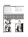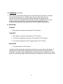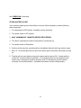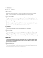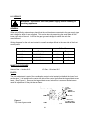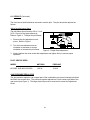
1
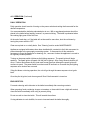
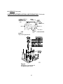
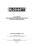
KLS-20G, KLS-40G and KLS-60G
GAS FIRED TRI-LEG STATIONARY KETTLE
INSTALLATION – OPERATION – MAINTENANCE
BLODGETT OVEN COMPANY
1
www.blodgett.com
44 Lakeside Avenue, Burlington, Vermont 05401 USA Telephone: (802) 658-6600 Fax: (802) 864-0183
S00064 Rev B (7/13)
IMPORTANT NOTES FOR INSTALLATION AND OPERATION
It is recommended that this manual be read thoroughly and that all instructions be followed
carefully.
This is the safety alert symbol. It is used to alert you to potential
personal injury hazards. Obey all safety messages that follow this
symbol to avoid possible injury or death.
FOR YOUR SAFETY: Do not store or use gasoline or other
flammable vapours or liquids in the vicinity of this or any other
appliance.
WARNING: Improper installation, operation, adjustment, alteration,
service or maintenance can cause property damage, injury or death.
Read the installation, operating and maintenance instructions
thoroughly before installing, operating or servicing this equipment.
PURCHASER: Instructions to be followed in the event that the operator of this
appliance smells gas must be posted in a prominent location. This information
shall be obtained by consulting the local gas supplier.
Do not obstruct the flow of combustion and ventilation air.
Keep the appliance area free and clear from combustibles.
Adequate clearances must be maintained for servicing and proper operation.
Do not attempt to operate this unit in the event of a power failure.
Intended for commercial use only. Not for household use.
This manual should be retained for future reference.
2
TABLE OF CONTENTS
DESCRIPTION
PAGE
Important Notes for Installation and Operation ................................................................. 2
1.0 Service Connections ................................................................................................. 4
2.0 Installation ................................................................................................................. 5
3.0 Performance Check .................................................................................................. 9
4.0 Operation ................................................................................................................ 10
5.0 Maintenance ........................................................................................................... 16
6.0 Service .................................................................................................................... 22
Adjustments ................................................................................................................... 24
Troubleshooting ............................................................................................................. 29
Appendix ‘A’, Material Safety Data Sheet ....................................................................... 31
3
1.0 SERVICE CONNECTIONS
UTILITY INFORMATION:
ELECTRIC:
1 STANDARD: 115/60/1 - furnished with 6 ft. cord w/3-prong
plug. Total maximum amps 2.0.
GAS:
KLS-20G-Total 100,000 BTU. One 1" male connection
(for location, see drawing below.) 1 Natural 1 Propane
Required operating pressure: Natural Gas 4" W.C.; Propane
Gas 10" W.C
1 OPTIONAL: 208/60/1 or for use on 3 (190 to 219 volts) supply must be wired to unit - see drawing below. Total
maximum amps 1.0.
KLS-40G - Total 100,000 BTU. One 1" male connection.
(for location, see drawing below.) 1 Natural 1 Propane
Required operating pressure: Natural Gas 4" W.C.; Propane
Gas 10" W.C
1 OPTIONAL: 240/60/1 or for use on 3 (220 to 240 volts) supply must be wired to unit - see drawing below. Total
maximum amps 1.0.
GL-60E - Total 130,000 BTU. One 1" male connection
(for location, see drawing below.) 1 Natura 1 Propane.
Required operating pressure: Natural Gas 4" W.C.; Propane
Gas 10" W.C.
DIMENSIONS
MODEL
KLS-20G
KLS-40G
KLS-60G
CAPACITY
UNITS
A
B
C
D
E
F
G
H
J
K
L
20 gallons
76 litres
40 gallons
152 litres
60 gallons
227 litres
inches
mm
inches
mm
inches
mm
20
508
26
660
30
762
31.25
794
35.5
902
40
1016
40
1016
44
1118
49.5
1257
32
813
38.5
978
42
1016
3
76
2
51
2.5
63
19
483
19
483
21.5
546
64
1626
72
1829
85
2159
24
610
29
737
35
889
30.5
775
35
889
39
991
6.0
152
6.0
152
8.0
203
18.25
464
22
559
24.62
625
KLS-20G = Ø 20.75"
KLS-40G = Ø 26.75"
KLS-60G = Ø 30.75"
GC
120° X 3
D
H
FRONT
EC
DIMENSIONS ARE IN INCHES [MM]
6(152)
CLOSED 5.5(140)
OPENED 7.5[191]
STANDARD
Ø 2(51] VALVE
E
B
ØA
G
L
C
J
EC
K
F
GC
4
EC
GC
2.0 INSTALLATION
INSTALLATION CODES AND STANDARDS
Installation must conform with local codes, or in the absence of local codes, with the National
Fuel Gas Code, ANSI Z223.1/NFPA 54, or the Natural Gas and Propane Installation Code,
CSA B149.1, as applicable.
1. The appliance and its individual shut off valve must be disconnected from the gas supply
piping system during any pressure testing of that system at pressures in excess of ½ psi
(3.5 kPa).
2. The appliance must be isolated from the gas supply piping system by closing its individual
manual shut off valve during any pressure testing of the gas supply piping system at test
pressures equal to or less than ½ psi (3.5 kPa).
Electrical grounding must be provided in accordance with local codes, or in the absence of local
codes, with the National Electrical Code, ANSI/NFPA 70, or the Canadian Electrical Code, CSA
C22.2, as applicable.
The electrical diagram is located on the inside of the console control cover.
EXHAUST FANS AND CANOPIES: Canopies are set over ranges, ovens and kettles for
ventilation purposes. It is recommended that a canopy extend 6" past appliance and be located
7.5 feet from the floor. Filters should be installed at an angle of 45 degrees or more with the
horizontal. This position prevents dripping of grease and facilitates collecting the run-off grease
in a drip pan, usually installed with the filter. A strong exhaust fan tends to create a vacuum in
the room and may interfere with burner performance or may extinguish pilot flames. Makeup air
openings approximately equal to the fan area will relieve such vacuum. In case of
unsatisfactory performance on any appliance, check operation with exhaust fan in the “OFF”
position.
WALL EXHAUST FAN: The exhaust fan should be installed at least 2 feet above the vent
opening at the top of the unit.
CLEARANCES: Adequate clearance must be provided in aisle and at the side and back.
Adequate clearances for air openings into the combustion chamber must be provided, as well
as for serviceability.
SIDES - 6 INCHES
BACK
- 2 INCHES AT FLUE BOX
FLOORS - 6 INCH LEGS OR 8 INCH LEGS
All units must be installed in such a manner that the flow of combustion and ventilation air are
not obstructed. Provisions for an adequate air supply must also be provided. Do not obstruct
the lower front or right side of the unit, as combustion air enters through these areas. The
bottom of the control area must also remain unobstructed.
5
2.0 INSTALLATION (Continued)
TO INSTALL
1. Uncrate carefully. Report any hidden freight damage to the freight company immediately.
2. Set the unit in place. Be certain to maintain minimum clearances as stated above.
3. To level the unit use a spirit level in all directions on the top of the kettle (lid up).
A. Units with legs - adjust the bottom foot on each leg to overcome an uneven floor.
B. Units with casters - loosen the locking nuts, turn casters in or out as required and tighten
locking nuts.
4. Be certain to leave adequate clearances for cleaning, maintenance and service.
5. The pressure relief valve is located at the left rear of the unit. This area should be kept clear
and should not be in an area where operators will normally stand. The elbow on the relief
valve should be turned toward the floor. A maximum 3 foot, 3/4" diameter pipe may be used
to extend to the floor, but must not be piped directly to a drain. It must vent to the
atmosphere.
6. Check the pressure gauge on the front panel before operating. If the pressure gauge does
not indicate green vacuum zone (below 0 psi), see “Re-establishing Vacuum” section under
SERVICE, after completing installation instructions.
GAS CONNECTION
The serial plate on the lower right side of the unit indicates the type of gas your unit is equipped
to burn. Do NOT connect to any other gas type.
A 1" NPT line is provided at the rear for the connection. Each unit is equipped with an internal
pressure regulator which is set for 4" W.C. manifold pressure for natural gas and 10" W.C. for
propane gas. Use 1/8" pipe tap on the burner manifold for checking pressure.
An adequate gas supply is imperative. Undersized or low pressure lines will restrict the volume
of gas required for satisfactory performance. A steady pressure, minimum 6" W.C. for natural
gas and minimum 11" W.C. for propane gas, is recommended. With all units operating
simultaneously, the manifold pressure on all units should not show any appreciable drop.
Fluctuations of more than 25% on natural gas, and 10% on propane gas, will create pilot
problems and affect burner operating characteristics. Contact your gas company for correct
supply line sizes.
6
2.0 INSTALLATION (Continued)
Purge the supply line to clean out any dust, dirt, or other foreign matter before connecting the
line to the unit. It is recommended that an individual manual shut off valve be installed in the
gas supply line to the unit. Use pipe joint compound which is suitable for use with LP gas on all
threaded connections. Test pipe connections thoroughly for gas leaks.
WARNING: All connections must be checked for leaks, after the unit
has been put in operation. Use soapy water only for testing on all
gases. Never use an open flame to check for gas leaks.
NOTICE: If applicable, the vent line from the gas appliance pressure regulator
shall be installed to the outdoors in accordance with local codes or, in the
absence of local codes, with the National Fuel Gas Code, ANSI Z223.1/NFPA 54,
or the Natural Gas and Propane Installation Code CSA B149.1, as applicable.
NOTICE: If this equipment is being installed at over 2,000 feet altitude and was
not so specified on order, contact service department. Failure to install with
proper orifice sizing may void the warranty.
WATER CONNECTION
On units equipped with an optional water fill valve connect a water line (minimum 1/4") to the
valve with a 1/4" NPT female fitting. Units with dual (hot and cold) valves must have the hot
water line connected to side with the hot water valve (red) and cold water line to the cold water
valve (blue). Plastic or rubber hose is not recommended, as it may melt against the hot kettle
side.
WARNING: For an appliance equipped with casters, the installation
shall be made with a connector that complies with the standard for
connectors for moveable gas appliances, ANSI Z21.69-CSA 6.16
and a quick-disconnect device that complies with the standard
for quick-disconnect devices for use with gas fuel, ANSI Z21.41CSA 6.9; adequate means must be provided to limit the movement
of the appliance without depending on the connector and the quick
disconnect device or its associated piping to limit the appliance
movement; the location where the restraining means may be attached
to the appliance is on bottom of unit directly below relief valve.
If the unit is also equipped with an optional water fill valve it too
must be installed with a flexible water supply tube, a quick disconnect
and strain relief.
7
2.0 INSTALLATION (Continued)
WARNING: Do not connect the appliance to the electrical supply until
after the gas connection has been made.
WARNING: ELECTRICAL GROUNDING INSTRUCTIONS
This appliance is equipped with a three-prong (grounding) plug for
your protection against shock hazard and should be plugged directly
into a properly grounded three-prong receptacle. Do not cut or
remove the grounding prong from this plug. (120V units only).
120 VAC - 60 Hz - Single Phase
Units with this electrical rating are factory supplied with a three-wire cord and three-prong plug
which fits any standard 120V, three-prong grounded receptacle. A separate 15 amp supply is
needed for each unit.
208/240 VAC - 60 Hz - Single and Three Phase
Units with this electrical rating are factory equipped with a transformer. To connect supply wires
remove cover from transformer box at right rear of unit. Route supply wires and ground wire
through the hole in the cover with a strain relief fitting. Connect wires to the primary transformer
terminals as required by your power supply voltage. Connect ground wire to ground lug.
Replace cover. Three-phase units are wired as above, using only two supply wires. The third
supply wire is not connected and must be properly terminated.
220 VAC - 50 Hz - Single Phase
Units equipped with this voltage rating should be wired exactly as in (2) above.
8
3.0 PERFORMANCE CHECK
The following items should be checked before or within the first 30 days of operation by a
qualified service technician.
1.0
Verify correct gas type.
2.0
Verify correct voltage, cycle and phase.
3.0
Gas pressure.
4.0
Internal gas connections.
5.0
Internal electrical connections.
6.0
Pilots - adjustment and ignition.
7.0
Burners - adjustment and ignition.
8.0
Thermostat - cycle for operation check.
9.0
Supply valve - check for operation.
10.0
Check hinge and lid assembly.
11.0
Draw-off valve - check operation.
12.0
Advise user on cleaning procedures.
9
4.0 OPERATION
Contact the factory, the factory representative or a local service company to perform
maintenance and repairs should the appliance malfunction.
WARNING: In the event of main burner ignition failure, a 5 minute
purge period must be observed prior to re-establishing ignition
source.
WARNING: In the event you smell gas, shut down equipment at the
main shut off valve and contact the local gas company or gas
supplier for service.
CAUTION: If you smell gas during the lighting procedure,
immediately shut off the gas supply until the leak has been
corrected.
GAS CONTROL INSTRUCTIONS:
Appliance does not require “Lighting” the pilot with a flame.
A. STARTUP
1. Turn thermostat to “OFF” position and power switch to “OFF” position.
2. Open control panel access door located on right side at bottom.
3. Turn dial on combination control to “ON” position by rotating control knob counter clockwise.
(NOTE: Any gas service valves exterior to the unit should be open.)
4. Turn “POWER” switch to “ON” position.
5. Set “COOK TEMP” to desired setting. The red “COOKING” pilot will be on until desired
setting has been reached.
6. At this time the spark igniter will begin sparking at the pilot until the pilot is ignited, or for
ninety seconds (an audible clicking sound will be evident).
10
4.0 OPERATION (Continued)
7. When the pilot is ignited the spark igniter will automatically stop and within 15 seconds
main burner gas will come on. If ignition does not occur, after a total of ninety
seconds, the unit will lockout, shutting off all gas although the spark igniter will
continue to spark. New installations (where there may be a considerable amount of air
in the gas line) may require the unit to be turned off and immediately back on
numerous times after each lockout period until the air is purged from the gas line.
B. SHUTDOWN
STANDBY
1. Place power on switch and thermostat to “OFF” position.
COMPLETE
1. Place power on switch and thermostat to “OFF” position.
2. Turn dial on combination control from “ON” position to “OFF” position.
3. Turn any main gas service valves supplying gas to “OFF” position.
RELIGHTING
1. Turn power switch to “ON” position.
It should be noted that the pilot and electronic ignition do not cycle with the thermostat. A
standing pilot is automatically established and monitored each time the power switch is
turned ON. If the pilot is ever extinguished by a momentary external interruption, the spark
igniter will automatically relight it without disturbing the cooking cycle, unless lockout occurs.
11
4.0 OPERATION (Continued)
SPARK IGNITER FAILURE:
In the event the spark igniter module fails the unit may still be operated by carefully following
these instructions.
1. Turn thermostat to OFF position; completely counter clockwise.
2. Turn power switch to OFF position.
3. WAIT A MINIMUM OF 5 MINUTES BEFORE PROCEEDING.
4. Turn dial on combination control to ON position (if not already on).
5. Turn power switch to ON position.
6. Wait two minutes and ten seconds and then immediately light pilot with long match or taper.
7. After 10 - 15 seconds gas valve will allow main burner gas to flow when thermostat is turned
on.
8. The pilot will now stay ignited as long as the power switch remains ON. If power switch is
turned OFF, repeat the above instructions. It is intended that the unit be operated in this
manner only in emergency situations and only while it is attended (do not leave pilot lit
overnight; shut off power switch). A qualified serviceman must be called promptly.
12
4.0 OPERATION (Continued)
FRONT PANEL CONTROLS:
1. Power Switch
This switch turns the main power to the unit on and off. It must be turned on to heat the
kettle. It should be turned off when the kettle will not be in use for long periods.
2. (Red) Cooking Light
This light is on whenever the main burner gas is on. On units with standing pilots this light
may be on without the burners being on if the pilot is extinguished. See lighting instructions.
3. (Amber) Low Water Light
All kettles are supplied with sufficient distilled water in the pressurized jacket. If at any time
the water level falls below that required for proper operation, the kettle will not heat and this
light will come on. See “Adding Water” section of service instructions.
4. Thermostat
The thermostat selects the desired internal kettle operating temperature.
5. Pressure Gauge
The pressure gauge indicates the internal operating pressure of the kettle. When cold, the
gauge should be in the green vacuum zone. If it is not, refer to “Re-establishing Vacuum”
section of service instructions. Under normal operation with the kettle empty (thermostat set
at 275 degrees Fahrenheit) the pressure shall reach 30 psi. When loaded the pressure may
be considerably less.
6. Sight Glass
The sight glass indicates the minimum and maximum water level within the kettle. If water
level falls below minimum level more distilled water should be added. See “Adding Water”
section of service instructions.
7. Pressure Relief Valve
The pressure relief valve is a safety device which prevents the internal kettle pressure from
ever exceeding 50 psi. It should never be tampered with.
13
4.0 OPERATION (Continued)
DAILY OPERATION
Daily operation should consist of turning on the power switch and setting the thermostat for the
desired temperature.
It is recommended the kettle be preheated prior to use. Milk or egg based products should be
placed in the kettle before heating, however, to prevent sticking. The kettle is preheated when
the cooking light goes off the first time.
At the end of each day, or if the kettle will not be used for some time, shut the unit down by
turning the power switch to OFF.
Clean as required or on a daily basis. See “Cleaning” section under MAINTENANCE.
Appliances equipped with casters have been installed with a restraint to limit their movement to
prevent damage to the gas supply connecting system. If disconnection of this restraint is
necessary to move the appliance for cleaning, etc., reconnect it when the appliance is moved to
its originally installed position.
Turning on the power switch initiates a pilot lighting sequence. The spark igniter will begin
sparking. The spark igniter will spark until the pilot is ignited. After ninety seconds lockout will
occur. Lockout shuts down all pilot (and main burner) gas flow although the spark igniter will
continue to spark. The power switch must be turned off and back on to restart the pilot lighting
sequence once lockout has occurred.
If the pilot blows out during operation, the unit will go through the same sequence to re-ignite
itself.
Once the pilot is ignited, main burner gas will flow if the thermostat is turned on.
END USER TIPS:
For easier cleaning add cold water to the kettle immediately after removing contents.
When preparing foods containing vinegar or tomatoes, or those which have a high salt content,
clean the kettle immediately after using to prevent pitting.
Do not use salt to clean the kettle. This will scratch the surface.
If using saltwater to cook shellfish, be sure to rinse and wash the kettle thoroughly.
14
END USER TIPS: (Continued)
Bring milk and egg products slowly up to temperature in a cold kettle to prevent product
adhering to the sides.
When planning actual cooking capacity, allow room at top for stirring without spilling.
When preparing puddings from a mix, place the powder in a cold kettle, add a small amount of
the liquid, and stir to form a thin paste. Turn on the kettle and add the remainder of the liquid.
Continue as per recipe instructions.
When browning meat bring the kettle up to temperature before adding. This seals in the juices
in the meat.
VENT SYSTEM: At least twice a year the unit venting system should be examined and
cleaned.
GAS SAVING TIPS
Use these reminders to help develop energy-saving procedures and habits. Using less natural
or propane gas saves energy as well as money.
1. Turn off when not in use.
2. Limit preheat times.
3. Use lid when possible.
4. Maintain equipment.
15
5.0 MAINTENANCE
Contact the factory, the factory representative or a local service company to
perform maintenance and repairs.
WARNING: Disconnect the power supply to the appliance before
cleaning or servicing.
Daily:
1. Wash exposed cleanable areas.
Monthly:
1. Clean around burner air mixers, louvered panels and pilots if grease or lint have
accumulated.
TWICE A YEAR: (minimum)
Have an authorized service person clean and adjust the unit for maximum
performance.
It is NOT RECOMMENDED to use cleaning agents that are corrosive.
Use of cleaning agents that contain chloride, acids or salts are corrosive and may cause pitting
and corrosion when used over a period of time; this will reduce life of the appliance.
Should pitting or corrosion occur this is not covered by warranty.
Follow the recommended cleaning instructions. Use a mild detergent, warm water and rinse
thoroughly.
Never spray water into electric controls.
NOTICE: Draw-off valve has a vulcanized rubber coated stem for better sealing.
Do not over tighten. This may cause the rubber to pull away from stem and
permanently damage it. This is not covered under warranty.
16
5.0 MAINTENANCE (Continued)
CLEANING INSTRUCTIONS
WARNING: Disconnect the power supply to the appliance before
cleaning or servicing.
WARNING: Never spray water into electric controls or components!
CAUTION: The equipment and its parts are hot. Use care when
operating, cleaning and servicing.
CAUTION: Do not use cleaning agents that are corrosive.
Your kettle should be cleaned immediately after each use or when cooking a different product.
Before cleaning, check that the kettle has cooled enough to touch it.
1. Rinse the inside of the kettle thoroughly and drain to remove any food particles.
2. Using a nylon brush, clean the kettle with a mild detergent and water. Never use steel wool
or scouring powder as it will scratch stainless steel. Plain steel wool can leave small pieces
of steel which can rust.
3. Rinse the inside of the kettle thoroughly with clean water. Drain the kettle by tilting or the
tangent draw-off valve, depending on model, to allow the detergent and water solution to
drain.
4. Wipe the exterior of the kettle with a clean, damp cloth.
WARNING: If you are cleaning a valve that is assembled to a kettle,
be sure the kettle is completely empty of any product.
17
5.0 MAINTENANCE (Continued)
CLEANING INSTRUCTIONS (Continued)
DRAW-OFF VALVE CLEANING
1. If equipped with a tangent draw-off valve, turn the large hex nut on the draw-off valve
counter clockwise until it is completely disengaged from the threads. Grasp the valve knob
and slowly pull out the valve stem and disk. Do not allow the disk to come in contact with
hard surfaces as it can be damaged and cause valve leakage. Wash the valve stem, disk
and handle. Insert a nylon brush, wet with detergent and water, into the valve body and
tangent draw-off tube. Brush vigorously.
2. Replace the valve stem assembly and turn the hex nut until snug. Rinse the kettle with
clean warm water.
3. Leave the draw-off valve open when the kettle is not in use.
DAIRY DRAW-OFF VALVE CLEANING
1. Remove the plug by first removing the handle, then turn the plug to line up with the pin and
pull with both hands. It is important to use both hands because the plug is heavy.
2. Put the plug in a plastic pail that contains a mild soap solution. A plastic pail works best, as
it reduces the possibility of nicking or scratching the plug. If the plug gets scratched it may
not seal correctly and could leak.
3. Use a soft cloth or soft brush and clean all surfaces.
4. Using both hands remove the valve from the soap and rinse well in another plastic pail that
contains fresh water.
5. Wash out the kettle as normal.
6. Once the kettle is washed out, return the plug into the body. Be sure the plug is inserted
into the notch and turned. Ensure the plug is tight and secure before letting go of it.
If you are cleaning a body and plug assembly, remove the plug and follow the above
procedures. When finished with the plug, follow the same instructions for washing the body.
Always use both hands when handling the plugs. Reassemble the plug into the body and use
as normal.
18
5.0 MAINTENANCE (Continued)
CLEANING INSTRUCTIONS (Continued)
WHAT TO DO IF SURFACE RUST APPEARS
Metal utensils should never be used as they will scratch the surface of the equipment and rust
may begin to form. To remove surface accumulation of rust from the inadvertent use of such
utensils, the following procedure may be used.
CAUTION: Improper use of this procedure may damage your
appliance!
1. Use undiluted white vinegar with a non-abrasive scouring pad (plastic) or cloth on the
affected area to remove the rust stain. The appliance should not be heated and remain at
room temperature during the entire cleaning process.
2. If the stain resists removal, additional exposure time with vinegar may be required, to a
maximum of one hour.
3. Thoroughly wash all of the vinegar away with fresh clear water. Dry the surface completely
and allow one hour before using the appliance to cook.
Following daily and period maintenance procedures will prolong the life for your equipment.
Climatic conditions - salt air - may require more thorough and frequent cleaning or the life of the
equipment could be adversely affected.
STAINLESS STEEL
To remove normal dirt, grease or product residue from stainless steel, use ordinary soap and
water (with or without detergent) applied with a sponge or cloth. Dry thoroughly with a clean
cloth. Never use vinegar or any other corrosive cleaner.
To remove grease and food splatters or condensed vapours that have baked on the equipment,
apply cleanser to a damp cloth or sponge and rub cleanser on the metal in the direction of the
polishing lines. Rubbing cleanser as gently as possible in the direction of the polished lines will
not mar the finish of the stainless steel. NEVER RUB WITH A CIRCULAR MOTION.
19
5.0 MAINTENANCE (Continued)
CLEANING INSTRUCTIONS (Continued)
STAINLESS STEEL (Continued)
Soil and burn deposits which do not respond to the above procedure can usually be removed by
rubbing the surface with SCOTCH-BRITE™ scouring pads or STAINLESS scouring pads. DO
NOT USE ORDINARY STEEL WOOL as any particles left on the surface will rust and further
spoil the appearance of the finish. NEVER USE A WIRE BRUSH, STEEL SCOURING PADS
(EXCEPT STAINLESS), SCRAPER, FILE OR OTHER STEEL TOOLS. Surfaces which are
marred collect dirt more rapidly and become more difficult to clean. Marring also increases the
possibility of corrosive attack. Refinishing may then be required.
TO REMOVE HEAT TINT: Darkened areas sometimes appear on stainless steel surfaces
where the area has been subjected to excessive heat. These darkened areas are caused by
thickening of the protective surface of the stainless steel and is not harmful. Heat tint can
normally be removed by the foregoing, but tint which does not respond to this procedure calls
for a vigorous scouring in the direction of the polish lines using SCOTCH-BRITE™ scouring
pads or a STAINLESS scouring pad in combination with a powdered cleanser. Heat tint action
may be lessened by not applying or by reducing heat to equipment during slack periods.
All food contact surfaces must be thoroughly drained and flushed prior to cooking in the kettle.
CONTROL PANEL: The textured control panel should be cleaned with warm water and mild
soap. Never use an abrasive cloth or steel wool. Never use cleaning solvents with a
hydrocarbon base.
20
SAFETY VALVE MAINTENANCE AND TESTING
CAUTION! Under normal operating conditions a “try lever test”
should be performed every two months. Under severe service
conditions, or if corrosion and/or deposits are noticed within the
valve body, testing must be performed more often. A “try lever test”
should also be performed at the end of any non-service period.
CAUTION! Hot, high pressure fluid may be discharged from body
drain and vent during “try lever” test. Care must be taken to avoid
any bodily contact.
CAUTION! High sound levels may be experienced during “try lever”
test. Wear proper safety equipment and exercise extreme care! Test
at, or near, half of the operating pressure by holding the test lever
fully open for at least two seconds to flush the valve seat free of
sediment and debris. Then release lever and permit the valve to
snap shut.
If lift lever does not activate, or there is no evidence of discharge,
turn off equipment immediately and contact a licensed contractor or
qualified service personnel.
21
6.0 SERVICE
WARNING: Disconnect unit from power supply before cleaning or
servicing appliance.
GENERAL
When any difficulty arises always check that the unit has been connected to the gas supply type
and voltage for which it was supplied. This can be done by examining the serial plate on the
lower right side of the unit. It will list the gas type and voltage for which the unit was
manufactured.
Wiring diagrams for the unit are located in a small envelope affixed to the rear side of the front
control panel.
Orifice Size
Unit
Total Input
Natural
Propane
KLS-20G
100,000 BTU/Hour
29
44
KLS-40G
100,000 BTU/Hour
29
44
KLS-60G
130,000 BTU/Hour
23
39
MANIFOLD PRESSURE
Natural Gas - 4 inches W.C.
LP Gas - 10 inches W.C.
PILOTS
The pilot adjustment is part of the combination control valve located just behind the lower front
access door. It is located on the center left side of the control just below the large slotted screw
head. (See Figure 1). Remove the large slotted screw; below this is a second slotted screw
used for adjustment of the pilot burner flame.
Figure 1
Top view of gas control
22
6.0 SERVICE (Continued)
The front burner shield should be removed to see the pilot. The pilot should be adjusted as
follows:
Adjust the pilot burner flame
The pilot flame should envelop 3/8 to ½ inch
[10 to 13 mm] of the igniter-sensor tip.
Refer to Figure 2. To adjust the pilot flame:
1. Remove the pilot adjustment cover
screw. Refer to Figure 1.
2. Turn the inner adjustment screw
clockwise to decrease or counter
clockwise to increase the pilot flame.
Figure 2 - Proper flame adjustment
3. Always replace the cover screw after adjustment and tighten firmly to ensure proper
operation.
PILOT ORIFICE SIZES:
MODEL
NATURAL
PROPANE
KLS-20G, KLS-40G, KLS-60G
.018 IN.
.010 IN.
GAS PRESSURE REGULATOR
The gas pressure regulator is an integral part of the combination gas control located just behind
the lower front access door. The pressure regulator adjustment is on the lower right side of the
gas control (see Figure 1). The large slotted cap must be removed to access the adjustment
screw.
23
6.0 SERVICE (Continued)
ADJUSTMENTS
To check the manifold pressure a pressure gauge (manometer) must be connected to the 1/8"
NPT pressure tap on the gas manifold. With the gas off, connect your pressure indicating
instrument to the manifold with a fitting appropriate for your instrument.
1. Turn the unit on; with main burners on, read the manifold pressure. The pressure should be
4 inches water column (W.C.) 2 inches W.C. for natural gas or 10 inches W.C. for propane
gas. Adjust the pressure regulator to obtain the appropriate pressure. Check serial plate on
lower right side of unit to confirm exact gas type and manifold pressure for your unit.
When pressure has been correctly adjusted turn unit off. Remove pressure indicating
instrument and replace the 1/8" NPT plug in manifold. Replace regulator cap and close access
door.
THERMOSTAT
The thermostat adjustment should not be changed. Check the following before changing the
thermostat:
1. With kettle cool, the pressure reading on the pressure gauge should be in the green
vacuum zone (below 0 psi). If not, see “Re-establishing Vacuum” section.
2. Check that the pressure switch is not set too high or too low and causing the out of
adjustment condition. A voltmeter should be used by a properly trained serviceman to
determine if the pressure switch or thermostat is actually cycling the burners. If the
pressure switch is found to be the problem, see “Pressure Switch” section.
After verifying that the pressure switch is set and operating properly, the thermostat may be
adjusted using the set screw inside the stem. The thermostat should cycle off at a gauge
pressure reading of 30 psi. Turn set screw clockwise to decrease pressure and counter
clockwise to increase pressure.
PRESSURE SWITCH
The pressure switch should not be adjusted until it is determined to be the cause of an operating
pressure deficiency. See “Thermostat” section to determine if the source of difficulty is the
pressure switch or thermostat.
The major difficulties caused by pressure switch mis-adjustment are:
24
6.0 SERVICE (Continued)
PRESSURE SWITCH (Continued)
1. Pressure relief valve opening, especially on preheat from a cold start to 275°F (135°C)
(pressure switch set too high).
2. Burners are being shut down by pressure switch, not the thermostat. (Pressure switch
set too low.)
The pressure switch is preset for proper operation from the factory. It is adjusted to the
maximum pressure, however not high enough to cause the pressure relief valve to open. This
setting will be slightly different on different kettles due to variations in the pressure relief valves.
During preheat to the maximum thermostat setting (275°F (135°C), from either a cold condition
or a lower temperature setting, the temperature may overshoot the thermostat setting and shut
down the burners by the pressure switch. This is normal, however, after the kettle cycles
several times (empty) the thermostat will begin cycling the unit.
TO ADJUST PRESSURE SWITCH:
1. To obtain access to the pressure switch, the front panel must be removed. Remove the
screws on either side of the panel. Be sure to support the panel to avoid excessive
strain on the wiring.
2. To increase the pressure setting turn the white ribbed knob clockwise; to decrease the
pressure, turn it counter clockwise. Use the center of the black ring as an indicator.
3. With the kettle empty and completely cold, bypass the thermostat by moving the single
terminal side wire to the double terminal side connector on the thermostat. Turn kettle
on.
4. Pressure in kettle (read pressure gauge on front panel) should reach a maximum of 35
psi and pressure relief valve should not open. Kettle pressure may rise 3 or 4 psi even
after burners shut down.
5. Relief valve should not open when kettle pressure is 40 psi; pressure switch setting is
satisfactory.
6. If relief valve opens, reduce setting on pressure switch, cool kettle completely by running
cold water through it and repeat steps 3 - 6.
7. If pressure in kettle is below 30 psi when burners shut off, increase setting of pressure
switch, cool kettle completely by running cold water through it and repeat steps 3 - 7.
8. When adjustment is complete, move wire from shorted terminal on the thermostat back
to the appropriate terminal and replace the front panel.
25
6.0 SERVICE (Continued)
ADDING WATER
It may be necessary to replenish water in the jacket when the low water indicator comes on. Do
so as follows:
•
Unit should be completely cold and off.
•
For reference, the total amount of distilled water contained in each unit, and amount to be
added in a low water condition is listed below:
Model
Total Amount of
Distilled Water
Amount of Water to be Added
in a Low Water Condition
KLS-20G
6 Gallons
135 fl. oz. (4 L)
KLS-40G
9 Gallons
236 fl. oz. (7 L)
KLS-60G
12 Gallons
338 fl. oz. (10 L)
RE-ESTABLISHING VACUUM:
With the kettle completely cold a vacuum of 25 to 30 inches mercury column (M.C.) should be
maintained as indicated in the green zone on the pressure gauge on the front control panel. If
at any time the vacuum is not in the green zone, vacuum should be re-established.
With the kettle empty, turn the thermostat knob to the highest temperature. When the pressure
gauge reaches 20 psi, turn thermostat off, open the pressure relief valve until pressure gauge
reads 1 psi, then sharply release it. This should remove the air and any loss in performance
should return.
Should the kettle fail to maintain a vacuum after repeated attempts to establish it, further checks
should be made to see if the pressure relief valve is leaking or if there are any leaks in the
pressure relief valve piping, copper lines going to the pressure switch, pressure gauge or
thermostat fitting.
CONTROL CIRCUIT FUSES
The control circuit is protected by a 3 amp. fuse which is located inside control panel, top right
side above transformer.
Should the unit fail to turn on, check this fuse by removing it and either replacing it or testing it
with a continuity tester. If the fuse is good, check the main power circuit breaker, which should
be external to the kettle.
26
6.0 CONVERTING BETWEEN NATURAL AND PROPANE GAS
WARNING: Fire or explosion hazard can cause property damage,
severe injury, or death.
1. Do not attempt to use a gas control set for natural gas on
propane gas or gas control set for LP gas on natural gas.
2. When making conversion, main and pilot burner orifices MUST
be changed to meet appliance manufacturer’s specifications.
Standard- or slow-opening gas controls may be converted from one gas to another. To convert
from natural gas to LP use the 393691 LP Conversion Kit that is included with the VR8304M
Gas Control. To convert from LP to natural gas use the 394588 Natural Gas Conversion Kit
(order separately). Step-opening gas controls cannot be converted.
To convert control from one gas to another:
•
Turn off main gas supply to the appliance.
•
Remove the regulator cap screw and pressure regulator adjusting screw. See Figure 1.
•
Remove the existing spring.
•
Insert the replacement spring with tapered end down. See Figure 2.
•
Install the new plastic pressure regulator adjustment screw so that the top of the screw is
flush (level) with the top of the regulator. Turn the pressure regulator adjustment screw
clockwise six complete turns. This provides a preliminary pressure setting of about 10.0
inch W.C. (2.5 kPa) for LP regulator and 3.5 inch W.C. (0.9 kPa) for natural gas regulator.
•
Check the regulator setting either with a manometer or by clocking the gas meter.
•
Install the new cap screw.
•
Mount conversion label on control.
•
Install control and appliance according to appliance manufacturer’s instructions.
27
6.0 SERVICE (Continued)
CONVERTING BETWEEN NATURAL AND PROPANE GAS (Continued)
Figure 1
Top view of gas control.
Figure 2
Installation of conversion kit
in regulated gas control.
28
TROUBLESHOOTING
PROBLEM
LOOK FOR
Unit will not come on
- Power switch is off.
- Unit not plugged in.
- Main power supply off.
- Bad electronic module.
- Bad low water control.
- Bad spark igniter.
- Bad intermittent pilot burner.
- Fuse in unit blown.
Unit will turn on electrically but will not heat
- Lockout has occurred.
- Thermostat not on.
- Gas control valve off.
- Main gas supply off.
- Low water.
- Bad thermostat.
- Bad pressure switch.
- Bad gas control valve.
- Bad spark igniter.
- Bad igniter cable.
- Bad intermittent pilot burner.
- Faulty gas control.
29
TROUBLESHOOTING:
PROBLEM
LOOK FOR
Excessive flame rollout on ignition, carboning
- Natural gas unit on propane.
- Excessive gas pressure.
- Incorrect orifice size.
- Faulty regulator in gas control.
Unit slow to preheat and slow to recover
- Propane gas on natural.
- Low gas pressure.
- Incorrect orifice sizes.
- Loss of vacuum.
- Faulty regulator in gas control.
Unit continuously locks out
- Pilot gas adjusted too low.
- Excessive draft condition.
- Excessive steam around bottom of unit
- Faulty transformer.
- Faulty electronic module.
- Faulty ignitor cable.
- Faulty spark igniter.
- Faulty gas control.
30
APPENDIX ‘A’
MATERIAL SAFETY DATA SHEET
PREPARATION INFORMATION:
Prepared for use in Canada by:
E H & S Product Regulatory Management Department
DOW CHEMICAL CANADA INC.
P.O. Box 1012
Sarnia, Ontario, N7T 7K7
(800) 331-6451
1. CHEMICAL PRODUCT AND COMPANY IDENTIFICATION
IN CASE OF EMERGENCY:
Fort Saskatchewan, Alberta: (780) 998-8282
Sarnia, Ontario: (519) 339-3711
Varennes, Quebec: (450) 652-1000
Product::
DOWFROST* HD HEAT TRANSFER FLUID, DYED
Product Code:
04632
Effective Date:
2/20/01
Date Printed: 07/10/02
MSD: 002239
DOW CHEMICAL CANADA INC.
P.O. Box 1012
Sarnia, Ontario, N7T 7K7
Prepared for use in Canada by the E H & S Product Regulatory Management Department;
Phone: (800) 331-6451.
COMPOSITION/INFORMATION ON INGREDIENTS
Propylene Glycol
CAS# 000057-55-6
Dipotassium Phosphate CAS# 007758-11-4
Deionized Water
CAS# 007732-18-5
94%
<5%
* or (R) indicates a trademark of The Dow Chemical Company.
31
<5%
HAZARDS IDENTIFICATION
EMERGENCY OVERVIEW
Clear yellow liquid. Odourless. Avoid temperatures above 450°F, 232°C.
POTENTIAL HEALTH EFFECTS (See Section 11 for toxicological data.)
EYE: May cause slight transient (temporary) eye irritation. Corneal injury is unlikely. Mists
may cause eye irritation.
SKIN CONTACT: Prolonged contact is essentially nonirritating to skin. A single prolonged
exposure is not likely to result in the material being absorbed through skin in harmful amounts.
Repeated exposures may cause flaking and softening of skin.
INGESTION: Single dose oral toxicity is considered to be extremely low. No hazards
anticipated from swallowing small amounts incidental to normal handling operations.
INHALATION: At room temperature, vapours are minimal due to physical properties. Mists
may cause irritation of upper respiratory tract (nose and throat).
SYSTEMIC (OTHER TARGET ORGAN) EFFECTS: Repeated excessive exposure to
propylene glycol may cause central nervous system effects.
CANCER INFORMATION: Did not cause cancer in laboratory animals.
TERATOLOGY (BIRTH DEFECTS): Birth defects are unlikely. Exposures having no adverse
effects on the mother should have no effect on the fetus.
REPRODUCTIVE EFFECTS: In animal studies, has been shown not to interfere with
reproduction.
* or (R) indicates a trademark of The Dow Chemical Company.
32
4. FIRST AID
EYES:
Flush eyes with plenty of water.
SKIN:
Wash off in flowing water or shower.
INGESTION:
No adverse effects anticipated by this route of exposure incidental
to proper industrial handling.
INHALATION:
Remove to fresh air if effects occur. Consult a physician.
NOTE TO PHYSICIAN:
No specific antidote. Supportive care. Treatment based on
judgment of the physician in response to reactions of the patient.
5. FIRE FIGHTING MEASURES
FLAMMABLE PROPERTIES
FLASH POINT:
214°F, 107°C (based on a similar material)
METHOD USED:
PMCC
AUTOIGNITION TEMPERATURE:
NOT DETERMINED
FLAMMABILITY LIMITS
LFL: Not determined
UFL: Not determined
HAZARDOUS COMBUSTION PRODUCTS: During a fire, smoke may contain the original
material in addition to unidentified toxic and/or irritating compounds. Hazardous combustion
products may include and are not limited to carbon monoxide and carbon dioxide.
* or (R) indicates a trademark of The Dow Chemical Company.
OTHER FLAMMABILITY INFORMATION: Violent steam generation or eruption may occur
upon application of direct water stream to hot liquids. Flammable concentrations of vapour can
accumulate at temperatures above 214ΕF. Liquid mist of this product can burn. Spills of these
organic liquids on hot fibrous insulations may lead to lowering of the autoignition temperatures
possibly resulting in spontaneous combustion. Container may rupture from gas generation in a
fire situation.
EXTINGUISHING MEDIA: Water fog or fine spray, carbon dioxide, dry chemical, foam. Alcohol
resistant foams (ATC type) are preferred if available. General purpose synthetic foams
(including AFFF) or protein foams may function, but much less effectively. Do not use direct
water stream. May spread fire.
33
MEDIA TO BE AVOIDED: Do not use direct water stream.
FIRE FIGHTING INSTRUCTIONS: Keep people away. Isolate fire area and deny unnecessary
entry. Burning liquids may be moved by flushing with water to protect personnel and minimize
property damage. Burning liquids may be extinguished by dilution with water. Do not use direct
water stream. May spread fire. Fight fire from protected location or safe distance. Consider
use of unmanned hose holder or monitor nozzles. Use water spray to cool fire exposed
containers and fire affected zone until fire is out and danger of re-ignition has passed.
Immediately withdraw all personnel from area in case of rising sound from venting safety device
or discolouration of the container. Move container from fire area if this is possible without
hazard.
PROTECTIVE EQUIPMENT FOR FIRE FIGHTERS: Wear positive-pressure self-contained
breathing apparatus (SCBA) and protective fire fighting clothing (includes fire fighting helmet,
coat, pants, boots and gloves). If protective equipment is not available or not used, fight fire
from a protected location or safe distance.
6. ACCIDENTAL RELEASE MEASURES (See Section 15 for Regulatory Information)
PROTECT PEOPLE: Use appropriate safety equipment. For additional information, refer to
Section 8, Exposure Controls/ Personal Protection.
PROTECT THE ENVIRONMENT: Avoid contamination of all waterways.
CLEAN-UP: See Section 13, Disposal Consideration.
* or (R) indicates a trademark of The Dow Chemical Company.
HANDLING AND STORAGE
SPECIAL PRECAUTIONS TO BE TAKEN IN HANDLING AND STORAGE: No special handling
requirements data available.
HANDLING: See Section 8, Exposure Controls/Personal Protection.
STORAGE: See Section 10, Stability and Reactivity.
EXPOSURE CONTROLS/PERSONAL PROTECTION
ENGINEERING CONTROLS: Provide general and/or local exhaust ventilation to control
airborne levels below the exposure guidelines.
PERSONAL PROTECTIVE EQUIPMENT
EYE/FACE PROTECTION: Use safety glasses. Safety glasses should be sufficient for most
operations; however, for misty operations wear chemical goggles.
34
SKIN PROTECTION: Use gloves impervious to this material.
RESPIRATORY PROTECTION: Atmospheric levels should be maintained below the exposure
guideline. When respiratory protection is required for certain operations, use an approved airpurifying respirator. In misty atmospheres, use an approved mist respirator.
EXPOSURE GUIDELINES: Propylene glycol: AIHA WEEL is 50 ppm total, 10 mg/m3 aerosol
only.
9. PHYSICAL AND CHEMICAL PROPERTIES
APPEARANCE/PHYSICAL STATE:
ODOUR:
VAPOUR PRESSURE:
VAPOUR DENSITY:
BOILING POINT:
SOLUBILITY IN WATER/MISCIBILITY:
SPECIFIC GRAVITY OR DENSITY:
Clear yellow liquid.
Odourless
0.22 mmHg @ 20°C
2.6
320°F, 160°C
Complete
1.058 @ 25/25°C
* or (R) indicates a trademark of The Dow Chemical Company.
10. STABILITY AND REACTIVITY
CHEMICAL STABILITY: Thermally stable at typical use temperatures.
CONDITIONS TO AVOID: Avoid use temperatures above 450°F, 232°C. Product can degrade
at elevated temperatures. Generation of gas during decomposition can cause pressure in
closed systems.
INCOMPATIBILITY WITH OTHER MATERIALS: Avoid contact with oxidizing materials. Avoid
contact with strong acids
HAZARDOUS DECOMPOSITION PRODUCTS: Hazardous decomposition products depend
upon temperature, air supply and the presence of other materials.
HAZARDOUS POLYMERIZATION: Will not occur.
11. TOXICOLOGICAL INFORMATION (See Section 3 for Potential Health Effects. For
detailed toxicological data, write or call the address or non-emergency number shown in
Section 1).
SKIN:
SKIN:
INGESTION:
The LD50 for skin absorption in rabbits is >10,000 mg/kg.
The LD50 for skin absorption in rabbits is >10,000 mg/kg.
The oral LD50 for rats is 20,000 - 34,000 mg/kg.
35
MUTAGENICITY:
In vitro mutagenicity studies were negative. Animal mutagenicity studies
were negative.
ECOLOGICAL INFORMATION (For detailed Ecological data, write or call the address or nonemergency number shown in Section 1.)
ENVIRONMENTAL FATE
MOVEMENT & PARTITIONING: Based largely or completely on data for major component(s).
Bioconcentration potential is low (BCF less than 100 or Log Pow less than 3). Potential for
mobility in soil is very high (Koc between 0 and 50).
* or (R) indicates a trademark of The Dow Chemical Company.
DEGRADATION AND PERSISTENCE: Based largely or completely on data for major
component(s). Material is readily biodegradable. Passes OECD test(s) for ready
biodegradability. Degradation is expected in the atmospheric environment within minutes to
hours.
ECOTOXICITY: Based largely or completely on data for major component(s). Material is
practically non-toxic to aquatic organisms on an acute basis (LC50/EC50 >100 mg/L in most
sensitive species).
DISPOSAL CONSIDERATIONS (See Section 15 for Regulatory Information)
DISPOSAL: DO NOT DUMP INTO ANY SEWERS, ON THE GROUND OR INTO ANY BODY
OF WATER. All disposal methods must be in compliance with all Federal, State/Provincial and
local laws and regulations. Regulations may vary in different locations. Waste
characterizations and compliance with applicable laws are the responsibility solely of the waste
generator. THE DOW CHEMICAL COMPANY HAS NO CONTROL OVER THE
MANAGEMENT PRACTICES OR MANUFACTURING PROCESSES OF PARTIES HANDLING
OR USING THIS MATERIAL. THE INFORMATION PRESENTED HERE PERTAINS ONLY TO
THE PRODUCT AS SHIPPED IN ITS INTENDED CONDITION AS DESCRIBED IN MSDS
SECTION 2 (Composition/Information On Ingredients).
FOR UNUSED & UNCONTAMINATED PRODUCT, the preferred options include sending to a
licensed, permitted: recycler, reclaimer, incinerator or other thermal destruction device.
As a service to its customers, Dow can provide names of information resources to help identify
waste management companies and other facilities which recycle, reprocess or manage
chemicals or plastics, and that manage used drums. Telephone Dow’s Customer Information
Center at 800-258-2436 or 989-832-1556 for further details.
36
14. TRANSPORT INFORMATION
DEPARTMENT OF TRANSPORTATION (D.O.T.): For D.O.T. regulatory information, if
required, consult transportation regulations, product shipping papers, or contact your Dow
representative.
CANADIAN TDG INFORMATION: For TDG regulatory information, if required, consult
transportation regulations, product shipping papers, or your Dow representative.
* or (R) indicates a trademark of The Dow Chemical Company.
15. REGULATORY INFORMATION (Not meant to be all-inclusive – selected regulations
represented).
NOTICE: The information herein is presented in good faith and believed to be accurate as of
the effective date shown above. However, no warranty, express or implied is given. Regulatory
requirements are subject to change and may differ from one location to another; it is the buyer’s
responsibility to ensure that its activities comply with federal, state or provincial, and local laws.
The following specific information is made for the purpose of complying with numerous federal,
state or provincial, and local laws and regulations. See other sections for health and safety
information.
* or (R) indicates a trademark of The Dow Chemical Company.
37
U.S. REGULATIONS
SARA 313 INFORMATION: To the best of our knowledge, this product contains no chemical
subject to SARA Title III Section 313 supplier notification requirements.
SARA HAZARD CATEGORY: This product has been reviewed according to the EPA “Hazard
Categories” promulgated under Sections 311 and 312 of the Superfund Amendment and
Reauthorization Act of 1986 (SARA Title III) and is considered, under applicable definitions, to
meet the following categories:
Not to have met any hazard category.
TOXIC SUBSTANCES CONTROL ACT (TSCA):
All ingredients are on the TSCA inventory or are not required to be listed on the TSCA
inventory.
STATE RIGHT-TO-KNOW: The following product components are cited on certain state lists as
mentioned. Non-listed components may be shown in the composition section of the MSDS.
CHEMICAL NAME
CAS NUMBER
LIST
1, 2-Propanediol
000057-55-6
PA1
PA1= Pennsylvania Hazardous Substance (present at greater than or equal to 1.0%).
OSHA HAZARD COMMUNICATION STANDARD:
This product is not a “Hazardous Chemical” as defined by the OSHA Hazard Communication
Standard, 29 CFR 1910.1200.
* or (R) indicates a trademark of The Dow Chemical Company.
38
CANADIAN REGULATIONS
WHMIS INFORMATION: The Canadian Workplace Hazardous Materials Information System
(WHMIS) Classification for this product is:
This product is not a “Controlled Product” under WHMIS.
CANADIAN ENVIRONMENTAL PROTECTION ACT (CEPA)
This product contains one or more substances which are not listed on the Canadian Domestic
Substances List (DSL). Contact your Dow representative for more information.
16. OTHER INFORMATION
MSDS STATUS: Revised to 16 section format.
The information herein is given in good faith, but no warranty, express or implied, is made.
Consult The Dow Chemical Company for further information.
* or (R) indicates a trademark of The Dow Chemical Company.
39