1
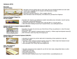
30 METER (10MHz)
CW TRANSMITTER
Ramsey Electronics Model No.
QRP30
THE RAMSEY QRP30 IS AN AMAZING PERFORMER
THAT WILL WORK THE WORLD ON ABOUT A WATT!
FOLKS OF ALL AGES HAVE SUCCESSFULLY BUILT
AND ENJOYED THIS EASY, FUN KIT.
•
Ideal for portable or travel fun
•
VCXO design allows up to 5 - 8 KHz of tuning about the crystal
frequency
•
Front panel switching of TWO channels and includes a crystal for
10.108 MHz, the International QRP frequency
•
Excellent and clean keying waveform
•
Built-in antenna T-R switch
•
Operates on 12 - 15 volts DC at 1/4 amp current
•
Appoximately 1 Watt RF power
•
Clear, concise step-by-step instructions carefully guide you to a
finished kit that not only works - but you’ll also learn too!
•
Proven design that has won many of awards for operators around
the country!
•
Add our case and knob set for a finished ‘Pro’ look. Cases match all
Ramsey products
QRP30 • 1
RAMSEY TRANSMITTER KITS
• FM100B Professional FM Stereo Transmitter
• FM25B Synthesized Stereo Transmitter
• AM1, AM25 AM Transmitters
• TV6 Television Transmitter
RAMSEY RECEIVER KITS
• FR1 FM Broadcast Receiver
• AR1 Aircraft Band Receiver
• SR2 Shortwave Receiver
• AA7 Active Antenna
• SC1 Shortwave Converter
RAMSEY HOBBY KITS
• SG7 Personal Speed Radar
• SS70A Speech Scrambler
• SP1 Speakerphone
• WCT20 Wizard Cable Tracer
• PH10 Peak hold Meter
• LC1 Inductance-Capacitance Meter
RAMSEY AMATEUR RADIO KITS
• DDF1 Doppler Direction Finder
• HR Series HF All Mode Receivers
• QRP Series HF CW Transmitters
• CW7 CW Keyer
• CPO3 Code Practice Oscillator
• QRP Power Amplifiers
RAMSEY MINI-KITS
Many other kits are available for hobby, school, Scouts and just plain FUN. New
kits are always under development. Write or call for our free Ramsey catalog.
30 METER CW TRANSMITTER KIT INSTRUCTION MANUAL
Ramsey Electronics publication No. QRP30 Revision 1.3
First printing: January 1995
COPYRIGHT 1994 by Ramsey Electronics, Inc. 590 Fishers Station Drive, Victor, New York
14564. All rights reserved. No portion of this publication may be copied or duplicated without the
written permission of Ramsey Electronics, Inc. Printed in the United States of America.
QRP30 • 2
Ramsey Publication No. QRP30
Price $5.00
KIT ASSEMBLY
AND INSTRUCTION MANUAL FOR
QRP30 30 METER CW
TRANSMITTER KIT
TABLE OF CONTENTS
Introduction to the QRP30 ............. 4
Understanding power levels........... 5
Circuit description .......................... 8
Simplified Block diagram ................ 8
Parts list ......................................... 9
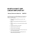
Schematic Diagram ...................... 10
Parts layout diagram .................... 11
Assembly instructions .................. 12
Crystal oscillator testing ............... 16
Initial tests .................................... 17
Verifying RF power ...................... 18
Maximizing RF power output ....... 19
Options for finishing project ......... 20
Enclosure ideas ........................... 20
Choosing crystals ......................... 21
Troubleshooting guide ................. 22
Ramsey kit warranty .................... 23
RAMSEY ELECTRONICS, INC.
590 Fishers Station Drive
Victor, New York 14564
Phone (585) 924-4560
Fax (585) 924-4555
www.ramseykits.com
QRP30 • 3
INTRODUCTION:
Most "QRP" transmitters are one-of-a-kind experimental circuits which take
some patience and fine-tuning to get clean keying and satisfactory
performance. Most QRP building projects presume either unlimited radio
junkboxes with all the right coils and capacitors, or that you have a lot of time
on your hands to track down needed parts. And that is part of what ham radio
can be all about. The purpose of the Ramsey Electronics series of QRP
transmitters is to give our amateur radio customers the option of picking up a
truly complete and reliable transmitter kit for whenever you need a compact
CW rig for a particular opportunity, perhaps a camping or business trip or a
weekend contest, or something economical to share with a favorite new
Novice.
This transmitter is a serious and practical device for radio amateurs with
general interests, as well as for QRP enthusiasts.
NOTE TO NEWCOMERS: "QRP" is amateur radio shorthand referring to
operation at "reduced power". As a standard "QRP30-signal", the CW
expression "QRP?" really means all of this: "If you are receiving me so well,
and since the FCC requires that we use minimum power necessary to
maintain useful communication, do you think I should reduce transmitting
power?" The act of reducing power output can be the switching off of a linear
power amplifier, or switching from 25 to 5 watts on your new Radio Shack 10
meter rig or turning back the carrier level control on most modern
transceivers. For equipment description and contest competition purposes,
"QRP" refers to transmitter powers under 5 watts.
In our manuals for the Ramsey Amateur Band receivers for the 80 and 40
meter bands, which tend to be of interest to many beginners because of
available Novice and Technician operating privileges, we try to be very basic
and patient, hoping that such an approach will be helpful to radio newcomers as well as to casual, licensed amateurs who just did not know that worthwhile
radio gear could be constructed at Ramsey's low prices, even in the 1990's.
Talking through a transmitter project presents a different challenge. Talking
through a multi-stage transmitter that delivers a grand total of one or two watts
to your antenna is an even greater challenge. In these times when a "barefoot
rig" is assumed to be an imported, digitally-synthesized transceiver putting out
over 100 watts at a cost of $1000-2000.00, we need a sensible and helpful
way of talking about this QRP transmitter you are about to construct.
It's easy to prove that Ramsey's popular and economical receivers work just
fine. Build one right, turn it on, and we become easily convinced. A
transmitter is a different story, especially a transmitter that runs low QRP
QRP30 • 4
power! Different from a receiver, you want to see some measurable output
power and you especially want to make two-way contacts!
If you're studying this manual before deciding to try this Ramsey "QRP"
transmitter project, perhaps the following discussion will be helpful to you. The
purpose of this manual is to help you construct this Ramsey Electronics 4stage, variable-frequency CW transmitter efficiently and successfully, not
necessarily to "sell" you on the merits and fun that have been discovered in
ham QRP operation. The purpose of the following discussion of power levels
and signal reports is simply to assure you that your new Ramsey QRP
transmitter is capable of serious, long-distance communication.
1000 WATTS vs 1 WATT: UNDERSTANDING THE DIFFERENCE
Before we move on, I would like to share with you a practical formula about
transmitter power that I clung to in my younger years when I could not afford
anything other than my original Novice CW transmitter, even well after I got
my Extra Class license. First, some theoretical facts we should know:
•
•
•
•
1. An "S-unit" on a receiver's S-meter or in the R-S-T system consists of a
6 - decibel increase or decrease of output power received from a
transmitter.
2. Power needs to be increased four times or 400% to result in a true 1 Sunit or 6db RST gain.
3. Reducing output power down to 25% of previous power should result in
an S- Meter or RST drop of only one 6-db unit.
4. A 10 - decibel increase in signal strength requires a power increase of
ten times!
Next, there are three practical facts to remember:
•
•
•
1. The R-S-T system was designed originally for the human ear and was
based on typical receiver performance of over 50 years ago.
2. Modern receiver design permits signals which are technically "weak" in
measured decibels to sound quite good (ie: 569-579) to the ear.
3. The human ear is sensitive enough to appreciate a 1 or 2 db change in
signal strength, which is why moderate changes in output power often
result in more dramatic signal report changes. (In fact, the value of a
decibel was determined to be that increment of sound change which
the ear could detect!)
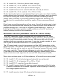
The following example shows RST reports to be expected, in exact theory, at
various power reduction levels. We will start with the classic 1000 watt station
QRP30 • 5
which gets a report of "10 db. over S-9" measured on the receiving station's Smeter. Assume identical dipole antennas at both stations. Our chart does not
start at the proverbial "30 db. over S-9" and work itself down to S-1 for
reasons that will become obvious.
S9+10 db.
S9
S8
S7
S6
S5
1000 watts output
100 watts output
25 watts output
6.25 watts output
1.56 watts output
.39 watts output
We can see that it becomes easy to play games with such numbers. For
example, an RST of 439 is a legitimate report which permits reasonably
effective communication. But, do we believe that the transmitting station
illustrated above could really produce a 439 signal by running .0013 watt? If
we say "probably not", we also ask why not, and then we would get the
seminars about perfect antenna matching, transmission line losses, and so
forth.
Under good propagation conditions, SSB signal reports of "20 over S-9" and
more can be given without even needing 1000 watts or a beam antenna.
Assuming the "+20" is an accurate report, consider this example of power
reduction over the same path:
S9+20db.
S9+10db.
S9
S8
S7
S6
S5
S4
1000 watts
100 watts
10 watts
2.5 watts
.625 watts
.156 watt
.039 watt
.0087 watt!
Under reasonably good band conditions, particularly at 10 or 14 MHz and on
up, the above correlation of signal reports to power output becomes realistic.
"S9+20" is what amplifier users expect to give and receive to justify their
investment and power consumption. Most commercial transceivers have
typical output in the 60-200 watt range, and S8-9 reports are taken for
granted. Actually, 15-25 watts is a far more practical operating power than
most amateurs and equipment vendors realize today...and the thousands of
QRP enthusiasts will confirm that getting a solid 579 running 3-4 watts is no
big deal.
If all the above theoretical signal reports are based on both the transmitting
and receiving stations using simple dipole antennas, we can also see that the
QRP30 • 6
use of some 10db gain antenna such as a beam or quad by either station
could move the S7 for .625 watt up to S8, and that a similar antenna used at
the other station could give the under 1 watt signal a further boost over S9!
On the other hand, if you hear a 1000 watt station producing a moderate
signal such as S4 or S5, you can reasonably assume that you will not have a
lot of luck over that path right now with the theoretical S1 signal level of your
QRP transmitter.
While these figures also can be used to show how nice it is to have a power
amplifier and beam antenna, they indeed serve to show that reasonable signal
levels indeed are achievable with low power and a dipole antenna.
"QRP" enthusiasts have their own rituals, jargon, strategies, QRP operating
contests, magazine columns and books, and convention get-togethers. They
constitute a vital segment of the amateur radio community, because they
consistently demonstrate the feasibility of low-power communication. In fact,
the most avid QRP enthusiasts would not regard communication with a
Ramsey transmitter especially challenging, since they prefer the new world of
milliwatt operation, known as "QRPp"! And, yes, the ones who have
conquered the "milliwatt" world ARE setting records with "milliwatt" tests. With
the world record set in 1970 between Alaska and Oregon on ONE microwatt,
think about it this way: your Ramsey QRP transmitter is almost one million
times more powerful than the transmitter used in that historic test!
WHO SHOULD USE A "QRP" TRANSMITTER?
There is a philosophy that "Novices" should not get started with a very low
power transmitter. The reasoning is that most newly-licensed amateurs need
to build up the confidence that comes with actually making contacts and that
they do not need the additional challenge and pressure of low-power
operation. There is some wisdom in this view, but that opinion should not
make newcomers apprehensive about trying a Ramsey QRP transmitter, IF:
1. This is where your budget is.
2. You can count on somebody to help you with assembly.
3. You can count on somebody to listen to your signal during initial
tests.
4. You have a reasonably good receiver.
5. You have space for a normal, no-compromise antenna for the band
you wish to operate, either a standard dipole, or the "inverted V"
dipole, or quarter-wave vertical.
QRP30 • 7
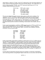
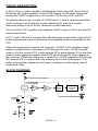
CIRCUIT DESCRIPTION:
In brief, Q1 is a crystal oscillator, amplified by buffer stage Q2, which drives
Q3 as the RF output amplifier. Q4 is a PNP keying circuit which opens and
closes the 12VDC supply line to Q1 and the T-R circuitry of D1 and D2.
S1 selects either of two crystals. R1,D3,D4 and L1 form a varactor controlled
series resonant circuit with the crystal. Adjusting R1 permits a crystal
frequency swing of up to 5 KHz, about the crystal frequency.
Q3 is a Class C RF amplifier that amplifies the RF output of Q2 to the final RF
power output level.
L6,C17 and C18 form a low pass filter (Butterworth) to match the output of Q3
to the antenna and reduce harmonics to acceptable levels as specified by the
FCC.
When the keying line is closed, Q4 conducts +12VDC to the oscillator stage,
applies a positive bias to the base of Q2 through R8, and +12VDC through
choke L4 to the anode of D1, which permits RF to pass through D1 to the filter
network while applying negative bias to D2 which blocks RF from passing to
the receiver. When the keying line is open, the +12VDC applied to D2 through
R13 permits D2 to conduct from the antenna jack to the receiver jack. The
buffer and amplifier stages are not keyed, resulting in clean keying, free of
chirps and clicks.
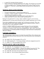
BLOCK DIAGRAM:
Q1
OSC.
A
Q2
BUFFER
Q3
FINAL
AMP
B
QRP30 • 8
D1,D2
DIODE
SWITCH
C17.L5,C18
LOW PASS
FILTER
PARTS SUPPLIED WITH QRP30 TRANSMITTER KIT:
CAPACITORS:
2 47 pf capacitor (C2,C6)
1 220 pf capacitor (marked 220 or 221) (C17)
2 470 pf capacitor (marked 470 or 471) (C3,C18)
11 .01 uf capacitors (marked .01 or 103 or 10 nf)(C1,4,5,7,8,9,10,13,14,15,19)
1 100 to 220 uf electrolytic capacitor (C16)
INDUCTORS:
3 100 uh inductor [looks like a resistor with brown-black-brown-silver or gold
bands] (L2,L4,L5)
1 2.2 uh inductor (green body with: red-red-gold-black color bands) (L1)
2 1.0 uh inductor (brown form with wire wrapped around body) (L3,L6)
RESISTORS:
3 100 ohms [brown-black-brown] (R7,R9,R11)
1 270 ohms [red-violet-brown] (R10)
1 470 ohms [yellow-violet-brown] (R6)
2 1K ohms [brown-black-red] (R12,13)
4 10K ohms [brown-black-orange] (R4,5,14,15)
1 47K ohms [yellow-violet-orange] (R8)
2 1 megohm [brown-black-green] (R2,3)
1 10K potentiometer (R1)
SEMICONDUCTORS:
1 2N3904 NPN transistor (Q1)
2 2N3053 NPN transistor (Q3,Q2)
1 PNP transistor (Q4) (marked 221-334 or ITT200) (similar to 2N3906)
1 1N4148 diode (small glass diode)
1 1N4002 diode (larger epoxy diode)
2 varactor diodes in TO-92 style case (D3,D4)
HARDWARE, OTHER COMPONENTS, MISC.:
1 Crystal "A" (10.108 MHz)
1 QRPTX printed circuit board
1 heatsink for Q3
3 RCA-style jacks (J1,2,3)
1 DC power jack (J4)
1 pushbutton switch (S1)
REQUIRED, NOT SUPPLIED:
12-14 volt 500 ma DC power source
Key, keyer or computer interface terminated to RCA plug
RF output indicator (see text)
10 MHz antenna and/or 50 ohm dummy load
QRP30 • 9
QRP30 • 10
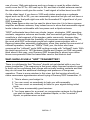
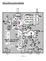
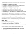
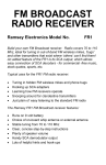
QRP30 PARTS LAYOUT DIAGRAM:
QRP30 • 11
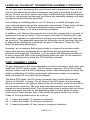
LEARN-AS-YOU-BUILD" TRANSMITTER ASSEMBLY STRATEGY:
As you can see in examining the circuit board and components, there is a bit
more to this transmitter kit than soldering a few parts and putting a signal on
the air. So that you don't spend extra time "troubleshooting" instead of getting
on the air, we strongly recommend you follow the assembly strategy and stepby-step procedures we are providing.
Our strategy in installing parts on our PC board is to install the larger and
more obvious parts such as the connectors and controls. These parts will then
act as "landmarks" so that each additional device installed is seen in
relationship to them, or to others previously installed.
In addition, we'll discuss the purpose of most of the components or groups of
components as we go along. If you are new to the idea of building your own
transmitter, perhaps our explanations will help you understand and learn as
we go along. The assembly sequence will follow the circuit flow from key jack
to antenna as faithfully as is practical, as part of Ramsey's "Learn-As-YouBuild" kit assembly philosophy.
However, we do assume that anyone ready to construct an amateur radio
transmitter has also developed some familiarity with general electronics
practices and language. Therefore, you can expect the following procedures
to move along with less of the hand-holding which we offer for our receivers
and other kit projects in which the FCC has less interest!
FIRST ASSEMBLY STEPS:
To get started and to put some landmarks on the circuit board, we'll insert and
install the 3 RCA "phono jacks", the DC power connector, the VCXO crystal
selector switch, and the VXO frequency control. With these parts in place, the
relative positioning of further components will become easier to recognize.
Refer frequently to your parts layout diagram.
The three RCA jacks, the DC power connector and crystal switch are all
"press- in-'til-flush" in design. On all three of the RCA jacks, the three large
tabs are soldered to the ground plane of the circuit board, while the thin tab is
for the center conductor. (Be sure these thin tabs make it into each of their
respective circuit board holes!) The crystal switch has a bottom with six circuit
board pins and a top with six corresponding tabs for other kinds of solder
connections. Press the pin side of the switch into place as far as it will go.
Press J4 into its position as far as it will go.
1. Insert and solder J1 (antenna connector)
2. Insert and solder J2 (receiver connector)
3. Insert and solder J3 (key, keyer or computer interface)
QRP30 • 12
4. Insert and solder J4 (DC power +12 to 14 volts)
5. Insert and solder R1, the 10K tuning potentiometer.
6. Insert and solder S1, pushbutton switch.
Carefully select, insert and solder the following components in the order given
in the following steps. Check off each step as completed.
7. C16, 100 to 220 uf electrolytic. Electrolytic capacitors are polarized,
which means there is a right and a wrong way to install them! Generally,
the Negative ( - ) side is indicated on the capacitor, while the Positive ( + )
is shown on the PC board. Make sure that the capacitor is inserted
correctly into the PC board with the ( + ) lead into the ( + ) hole and the
( - ) lead into the ( - ) hole.
8. R11, 100 ohm (brown-black-brown).
9. C19, .01 uf (marked .01 or 103 or 10 nf).
10. D2, 1N4148 diode. This diode is the small glass bead type. For correct
polarity, the dark band must face as shown on the parts layout diagram.
11. C10, .01 uf (marked .01 or 103 or 10 nf).
The preceding parts comprise much of the circuitry which blocks RF from the
receiver during transmission and permits the antenna to be connected to the
receiver jack during "key-up" conditions. To further complete this section of
the circuit, we now install the first of three 100 uh RF chokes. They look like
resistors with brown-black-brown-silver (or gold) bands. In the following steps,
be sure to save the clipped-off component lead wires from R12 and R13.
These will be used for "jumpers" in later steps.
12. Install L5, 100 uh inductor. (brown-black-brown-silver)
13. Install R12, 1K resistor (brown-black-red).
14. Install R13, 1K resistor (brown-black-red).
15. Using a scrap component lead wire, install Jumper JMP1. Jumper
wires simply connect two PC board traces together, jumping over other
traces!
16. Install R8, 47K (yellow-violet-orange).
17. Install C7, .01uf (marked .01 or 103 or 10nf)
Next study the orientation of Q4, the keying transistor. Be careful in identifying
Q4. Q4 is the only PNP device, and its part number or case style may vary
slightly. If necessary, positively identify Q1, the 2N3904 oscillator transistor,
and set it aside for later, since Q4 is similar or identical in style. Proceed with
the following steps, in order, once you are positive you have selected Q4 as
the 221-334 PNP transistor.
QRP30 • 13
18. Install R15, 10K ohms (brown-black-orange).
19. Install C13, .01 uf (marked .01 or 103 or 10 nf).
20. Install R14, 10K ohms (brown-black-orange).
21. Install Q4, be sure to orient its flat side correctly as shown.
22. Install C15, .01 uf (marked .01 or 103 or 10 nf).
So far, here's what we've accomplished. First, we've got over a third of all the
parts soldered onto the board, which should make you happy, and you should
be used to locating the correct component holes with increasing ease by
seeing them in relation to previously installed components. Secondly, the
keying circuit is completed and would be usable, if there was something to
key.
From here, we could proceed one of two ways. It would be quite easy to start
filling in the holes around the antenna jack, and the project could be done in
perhaps another hour. We'd like to suggest a better approach, which is to
build up the VXO stage (variable-crystal-oscillator) around Q1 and test it
before finishing the rest of the transmitter.
BUILDING THE VXO (VARIABLE CRYSTAL OSCILLATOR):
Your QRP transmitter comes complete with one crystal in the CW range,
usually the suggested QRP international calling frequency. S1 permits your
choice of any two installed crystals, the one that comes with your kit and
another which you may add on your own. If you plan to add a socket for your
own crystal, it should be wired to the "A" crystal position.
The PC board used in your kit is common to all the QRP transmitters in the
Ramsey Kit line. This means that there are some component locations on the
PC board that may not be used on your kit. Please be aware of this and install
your parts carefully. The parts layout diagram is quite clear regarding this.
(The reason for these holes is that different frequency bands require various
styles of inductors and capacitors for correct VXO frequency and shift).
Now, since we have gone to all this explaining, let's install some more parts!
23. Install L1, 2.2 uh inductor (green body with two red bands).
24. Install C1, .01 uf (marked .01 or 103 or 10 nf).
25. Install R2, 1 megohm (brown-black-green).
26. Install Varactor diode D3, observe correct placement of the flat side.
(Varactor diodes act as a variable capacitor whose capacity is varied by
the voltage applied across it).
27. Install varactor diode D4, observe flat side placement.
QRP30 • 14
28. Install R3, 1 megohm (brown-black-green).
29. Install R4, 10K (brown-black-orange).
30. Install C2, 47 pf.
31. Install C3, 470 pf (marked 470 or 471).
32. Install R6, 470 ohms (yellow-violet-brown).
With the above components installed correctly, the three holes for Q1 should
be clearly apparent. Make sure Q1 is correctly identified as a 2N3904.
33. Install Q1, 2N3904. Orient its flat side correctly.
34. Install C5, .01 uf
35. Install R7, 100 ohms (brown-black-brown).
36. Install C4, .01 (marked .01 or 103 or 10 nf).
37. Install R5, 10K ohms (brown-black-orange).
38. Install C6, 47 pf.
It's time to decide which crystal(s) are to be installed in which position and to
install at least one of them for testing. Notice that there are two pairs of holes
for each crystal connection, so that you can install virtually any standard
crystal case style.
HALFTIME SUGGESTION
It won't be too much longer before your Ramsey transmitter is ready for testing
and on-the-air operation. It is common for experimental projects to give
disappointing results because of inefficient "haywire" hookups as soon as they
are completed. This is most especially true with low power transmitters! To try
out this transmitter, you will need the following, and we'll offer suggestions
about each of them:
◊
◊
◊
◊
A healthy and CLEAN source of 12-14 volts DC, connected with
CORRECT POLARITY. A power supply or battery capable of 500 mA is
required.
A receiver capable of CW reception on the same band as this transmitter,
with a coaxial antenna line terminated in a plug or adapter to mate with
the receiver jack on this transmitter.
A resonant antenna with a 50 ohm coaxial feedline such as RG58,
terminated in a plug or adapter to mate with the RCA antenna jack on this
transmitter.
A CW key, keyer or computer interface connected to a cable terminated in
a plug or adapter to mate with the RCA key jack on this transmitter. It is
preferable but perhaps not essential that this cable be shielded.
QRP30 • 15
◊
◊
A valid FCC Amateur Radio License.
Some method of verifying satisfactory RF output. We will give you several
of these in detail in the "Verifying Transmitter RF power Output" section
on page 18. Feel free to read ahead before picking up the soldering iron
again.
CRYSTAL OSCILLATOR TESTING:
◊
◊
◊
◊
Connect a key, keyer or momentary switch to J3.
Connect +12VDC to power connector J4. Note that the CENTER
connection is the positive (+) side.
Tune a nearby receiver to the anticipated crystal frequency.
Make sure that S1 is set to the correct crystal position.
Keying J3 should result in a crisp, clean oscillator signal in your receiver.
Adjusting the R1 tuning control should vary the crystal frequency up to 5 KHz.
If you have installed a second crystal, test it in the same manner. Also, you
will notice that the VXO circuit usually swings the frequency down, a fact to
remember if you order additional crystals.
NOTE TO NEWCOMERS:Please be aware that even this one transistor
oscillator is itself a transmitting device, quite capable in good propagation
conditions of emitting an RF signal and HARMONICS, when and if connected
to an antenna. It is correct practice to keep your test brief and to identify them
with your callsign.
FURTHER ASSEMBLY;
The following three steps connect a simple low-pass filter to the antenna jack.
The low-pass filter prevents harmonics from the transmitter from reaching the
antenna.
39. Install C18, 470 pf (marked 470 or 471).
40. Install inductor L6, 1 uh (brown bodied with wire wrapped around it).
41. Install C17, 220 pf (marked 220 or 221).
BUFFER AND RF AMPLIFIER WIRING:
42. Install C8, .01 uf (marked .01 or 103 or 10 nf).
43 Install Q2, marked 2N3053. Observe the case of transistor Q3. The
small metal case tab must be oriented correctly! Please be careful.
44. Install R9, 100 ohms (brown-black-brown).
45. Install L2, 100 uh (brown-black-brown-silver).
QRP30 • 16
The buffer stage is now completed and connected to the base of the power
amplifier stage, Q3.
46. Install R10, 270 ohms (red-violet-brown).
47. Install L3, 1 uh inductor (brown body with wire wrapped around it).
48. Install C14, .01 uf (marked .01 or 103 or 10 nf).
49. Install C9, .01 uf (marked .01 or 103 or 10 nf).
50. Install D1, 1N4002 (large black epoxy body), notice placement of
banded end.
51. Install L4, 100 uh inductor (brown-black-brown-silver).
52. Install Q3, 2N3053. Again observe the placement of the tab.
53. Install the slip-on metal heatsink on Q3. Insure that it does not contact
adjacent components.
The assembly of your QRP transmitter is now completed. If you somehow
skipped or improvised on our "halftime" instructions, NOW is the time to make
proper preparations for testing and using your transmitter.
As we suggest in all Ramsey Electronics kit projects, now might also be an
excellent time to take a break and then come back to re-check your
connections, or have a friend go over them. Give extra attention to the work
associated with Q2 and Q3. It's always easier to catch an error now, before
final testing. Easier on the cicuit parts, and. . . your ego!
INITIAL TESTS:
Connect the following to the transmitter:
Key, or keyer such as the Ramsey CW-7 CMOS keyer kit.
12-15 VDC power source capable of 500 ma output.
Resonant antenna with in-line QRP wattmeter, or 50-ohm 2-watt dummy
load.
For initial testing, your receiver may be connected through J2 of the
transmitter or to a separate receiving antenna.
•
Study the following sections regarding the DC power supply and RF
power indication, and test your transmitter in accord with good amateur
radio practice.
QRP30 • 17
YOUR POWER SUPPLY AND RF OUTPUT POWER :
For optimum performance, one or two volts of extra DC supply power can
make quite a difference for this transmitter. For example, two lantern batteries
in series, or 8 "D cells" obviously provide "about 12 volts" with sufficient
current capability for casual operating. For maximum RF output power, use a
supply of 14 to 15 volts DC. The easiest method is to place two fresh "D cells"
in series with your power source, if a full 13.6-15 volts DC is not available.
If your supply voltage is in the 11-12 volt range, you can expect a 200 to 250
ma current flow and about one-half watt of the RF output power. With a solid
14 to 15 volt supply, you can expect about 400 ma current draw and up to one
watt of RF output power.
VERIFYING TRANSMITTER RF OUTPUT:
The most important thing to know is whether your transmitter is delivering
some measurable and reassuring level of RF power to the antenna. The sound
of the transmitter's keying in a receiver is of some help, but even the simplest
crystal oscillator can send a fine signal into your neighbor's receiver, as we
have already discussed.
Ideally, you have an small RF wattmeter, already inserted in the antenna line,
capable of accurately measuring low output power in watts and even
milliwatts! And it cost you less than what you paid for the transmitter kit. Right?
If not, we have a few other ideas for you, OK?
Saying the same thing one more way, we assume you already know that
accurate, commercially built RF wattmeters cost much more than what you
paid for this Ramsey transmitter kit.
Since this solid-state transmitter does not require tuning or adjustments, a
periodic power output check-up should suffice. If you do not own or have
access to a low-level RF power meter, use a trick that is decades old, the
common flashlight or panel bulb. All you need to know is the basic differences
between bright, superbright, dim, unlit and burned out! Using such a bulb to
check power output is also a satisfying way to put Ohm's Law to work. Your
Radio Shack catalog specifies operating voltage and current in milliamperes
for a variety of small replacement lamps. It could be worth your time to make
up a simple plug-in "output tester" for your transmitter, a male RCA plug
connected to a socket for the bulb of your choice or even soldered directly to
the bulb.
Rf voltage levels in this transmitter can vary from 2 to 10 volts RMS depending
on various factors. Typically, 1 watt power levels are achieved in 5-7 volts
RMS volts range. A good test bulb for this level is the PR-4 flange-style
QRP30 • 18
flashlight bulb or the type 243 bulb with screw-in body. Both are rated to give
normal brilliance at 2.33 volts, drawing 270 milliamps of current. Using Ohm's
Law P=IE, we see that normal brilliance requires 2.33 volts x .270 amperes
for .62 watts of DC power consumption. We can conclude that even 1/2 watt or
so of RF should light this bulb reasonably well. A type PR-12 bulb is suitable for
checking RF outputs in the 1-3 watt range. Try it out!
Please remember, though, that a flashlight bulb does NOT present the proper
load impedance to the transmitter output, so theoretical calculations based on
the bulb`s rating can only be approximate. For example, the PR-4 at full
brilliance presents only an 8.2 ohm load to the transmitter.
If ANY flashlight bulb lights up when connected to the antenna jack of this
transmitter, you can be satisfied that you have RF output power ROUGHLY
comparable to the DC power rating of the bulb you are using. If you burn out
your bulb, rejoice and put your rig on the air!
Amateur radio magazines and handbooks provide a variety of circuits for RF
wattmeters and relative field-strength indicators, including methods of using
your VOM as an indicating device. CQ magazine for March 1990 offers an
article by KB4ZGC on how to make a highly accurate yet inexpensive dummy
load and wattmeter capable of showing 1/10-watt differences in RF power.
MAXIMIZING RF POWER OUTPUT:
Hopefully, the introductory discussion about the amount of power increase
needed for significant boosts in RST reports will satisfy most users that good
communication opportunities are afforded by the transmitter's QRP output. The
simplest way to ensure maximum reasonable power output without component
damage is to run the DC voltage in the 14 to 15 volt range, observing a
maximum limit of +18VDC.
IMPORTANT NOTE: If you are experimenting with this transmitter and see a
sudden and massive increase in power output and DC current, you have not
reached the promised land or created a 25 watt transmitter! Sudden surges like
that are a sure sign of amplifier self-oscillation. Kill the DC power supply
immediately, because your Q3 RF power transistor has headed to selfdestruction while probably interfering with every TV set in the neighborhood. A
poorly matched antenna along with higher supply voltages is usually
responsible for this occuring. Any prolonged "parasitic" emissions will also
overheat and destroy the components in the Q4 keying circuit.
Please remember that modified PC boards are not eligible for factory repair
service. We encourage experiments and improvements of basic Ramsey kits,
but we ask that you first get the kit working as designed and understand it before making ANY changes. We regretfully cannot offer any other guidance in
modifying our kits. You're on your own, that's what experimenting is all about!
QRP30 • 19
TRANS-RECEIVE OPERATION:
If you plan to use this transmitter with a Ramsey HR-series direct conversion
receiver for portable operation, it will be necessary to work out a receiver
muting and keying sidetone circuit. A matching companion to your transmitter
is the new Ramsey CW-7 CMOS Keyer, with built-in sidetone.
This transmitter is an ideal travel companion to the growing number of portable
shortwave broadcast receivers which feature digitally synthesized tuning,
memories and other features, provided that a BFO for CW-SSB reception is
one of the features. In most cases, transmitter keying can be monitored
directly from such receivers without too much overload, though it may be
necessary to rig a simple switch to mute or attenuate the audio or short the
antenna input to ground while transmitting.
THE RAMSEY ELECTRONICS CASE, KNOB & HARDWARE
OPTION:
Your finished transmitter can be installed in a variety of enclosures of your
own design and choosing. You might be planning to combine several Ramsey
circuit kit boards in a single enclosure. Use of the inexpensive and attractive
Ramsey case and knob set will give your unit that nice finished look and
increase its resale value. These sturdy black instrument cases are supplied
with printed overlayes on front and rear panels, knobs, rubber feet and
mounting screws.
OTHER ENCLOSURE RECOMMENDATIONS:
While we believe that the Ramsey enclosure and knob option is a fine value
for finishing off your Ramsey receiver or transmitter, we are happy to give you
a couple of additional suggestions and our reasons for them. If your first goal
is economy and rugged portability, you will find that the circuit board can be
mounted nicely in a standard VHS videotape storage box, which also gives
room for storing cables, a small homemade keyer, etc. The controls are easily
mounted at one end of such a box. It may be necessary to cut away the
molded posts which secure the tape itself. These storage boxes come in
several styles, so pick one which truly looks practical as a project enclosure.
To accomplish RF shielding, the most economical metal enclosure nicely
suited for Ramsey amateur kit board is Radio Shack No. 270-253A. This metal
utility cabinet can accommodate both a receiver and transmitter board, plus
speaker, with room for various refinements you might like to add.
QRP30 • 20
NOTE ON CHOOSING, ORDERING CRYSTALS:
When ordering crystals for Ramsey QRP transmitters, specify 32 picofarad load
capacitance, parallel resonance, HC-6/U or HC-18/U holder, although virtually
any crystal will work. The back of Ham magazines have ads for many different
crystal suppliers (one source is JAN Crystals, 1-800-JAN-XTAL), any of whom
are excellent. A variety of crystal styles may be used, but do not expect to get
satisfactory output and keying from surplus crystals in the old WW-II, FT-243
holders which may have been opened and modified over the years.
FINAL CONSIDERATIONS:
Our earlier discussion of how a watt of RF output can indeed offer satisfying
communications has several presuppositions:
1. A resonant antenna (dipole or quarter-wave vertical)
2. Good quality coaxial feedline and connectors
3. An effective earth ground
We cannot expect good results from low levels of RF output if the power gets
wasted in lousy coax, corroded connections, or poor antennas. However, you
also will be interested to know that test QSO's, including DX, were made with
this Ramsey transmitter using both a mobile whip antenna and simple dipole on
the balcony of a condo building.
If you elect to use an antenna tuner, it is extremely important that you
understand exactly how to use tuners and what they can and cannot do. A watt
of RF can easily become lost in an incorrectly adjusted antenna matching
device. The whole idea of this transmitter is to keep things simple and
economical, so we cannot overemphasize the priority of a clean, efficient
connection of the transmitter output to a resonant antenna.
QRP30 • 21
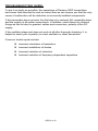
TROUBLESHOOTING GUIDE:
To put it as kindly as possible, the operations of Ramsey QRP transmitters
have been field-checked to such an extent that we can assure you that the only
cause of malfunction will be defective or incorrectly installed components.
If the transmitter does not work, the first step is to recheck ALL assembly steps
and the quality of all solder connections. In addition, check those too obvious
things we like to take for granted: cables and connectors, polarity of the DC
supply.
If the oscillator stage just does not work at all after thorough checking, it is
helpful to check your crystal(s) in a test oscillator or other transmitter.
Common trouble spots include:
Incorrect orientation of transistors
Incorrect installation of diodes
Incorrect selection of inductors
Incorrect selection of frequency-dependent capacitors
QRP30 • 22
The Ramsey Kit Warranty
Please read carefully BEFORE calling or writing in about your kit. Most problems can be
solved without contacting the factory.
Notice that this is not a "fine print" warranty. We want you to understand your rights and ours too! All
Ramsey kits will work if assembled properly. The very fact that your kit includes this new manual is your
assurance that a team of knowledgeable people have field-tested several "copies" of this kit straight
from the Ramsey Inventory. If you need help, please read through your manual carefully, all information
required to properly build and test your kit is contained within the pages!
1. DEFECTIVE PARTS: It's always easy to blame a part for a problem in your kit, Before you conclude
that a part may be bad, thoroughly check your work. Today's semiconductors and passive components
have reached incredibly high reliability levels, and it’s sad to say that our human construction skills have
not! But on rare occasions a sour component can slip through. All our kit parts carry the Ramsey Electronics Warranty that they are free from defects for a full ninety (90) days from the date of purchase.
Defective parts will be replaced promptly at our expense. If you suspect any part to be defective, please
mail it to our factory for testing and replacement. Please send only the defective part(s), not the entire
kit. The part(s) MUST be returned to us in suitable condition for testing. Please be aware that testing can
usually determine if the part was truly defective or damaged by assembly or usage. Don't be afraid of
telling us that you 'blew-it', we're all human and in most cases, replacement parts are very reasonably
priced.
2. MISSING PARTS: Before assuming a part value is incorrect, check the parts listing carefully to see if
it is a critical value such as a specific coil or IC, or whether a RANGE of values is suitable (such as "100
to 500 uF"). Often times, common sense will solve a mysterious missing part problem. If you're missing
five 10K ohm resistors and received five extra 1K resistors, you can pretty much be assured that the '1K
ohm' resistors are actually the 'missing' 10 K parts ("Hum-m-m, I guess the 'red' band really does look
orange!") Ramsey Electronics project kits are packed with pride in the USA. If you believe we packed an
incorrect part or omitted a part clearly indicated in your assembly manual as supplied with the basic kit
by Ramsey, please write or call us with information on the part you need and proof of kit purchase
3. FACTORY REPAIR OF ASSEMBLED KITS:
To qualify for Ramsey Electronics factory repair, kits MUST:
1. NOT be assembled with acid core solder or flux.
2. NOT be modified in any manner.
3. BE returned in fully-assembled form, not partially assembled.
4. BE accompanied by the proper repair fee. No repair will be undertaken until we have received the
MINIMUM repair fee (1/2 hour labor) of $25.00, or authorization to charge it to your credit card
account.
5. INCLUDE a description of the problem and legible return address. DO NOT send a separate letter;
include all correspondence with the unit. Please do not include your own hardware such as
non-Ramsey cabinets, knobs, cables, external battery packs and the like. Ramsey Electronics, Inc., reserves the right to refuse repair on ANY item in which we find excessive problems or
damage due to construction methods. To assist customers in such situations, Ramsey Electronics, Inc., reserves the right to solve their needs on a case-by-case basis.
The repair is $50.00 per hour, regardless of the cost of the kit. Please understand that our technicians
are not volunteers and that set-up, testing, diagnosis, repair and repacking and paperwork can take
nearly an hour of paid employee time on even a simple kit. Of course, if we find that a part was defective
in manufacture, there will be no charge to repair your kit (But please realize that our technicians know
the difference between a defective part and parts burned out or damaged through improper use or assembly).
4. REFUNDS: You are given ten (10) days to examine our products. If you are not satisfied, you may
return your unassembled kit with all the parts and instructions and proof of purchase to the factory for a
full refund. The return package should be packed securely. Insurance is recommended. Please do not
cause needless delays, read all information carefully.
QRP30 • 23
30 METER CW TRANSMITTER KIT
Quick Reference Page Guide
Introduction ....................................4
Understanding power levels ...........5
Circuit description ...........................8
Parts list ..........................................9
Schematic Diagram ......................10
Parts layout diagram .....................11
Assembly instructions ...................12
Initial tests .....................................17
Troubleshooting guide ..................22
Ramsey kit warranty .....................23
REQUIRED TOOLS
• Soldering Iron Ramsey WLC100
• Thin Rosin Core Solder Ramsey RTS12
• Needle Nose Pliers Ramsey MPP4 or
RTS05
• Small Diagonal Cutters Ramsey RTS04
<OR> Technician’s Tool Kit TK405
ADDITIONAL SUGGESTED ITEMS
• Holder for PC Board/Parts Ramsey HH3
• Desoldering Braid Ramsey RTS08
• Digital Multimeter Ramsey M133
Price: $5.00
Ramsey Publication No. QRP30
Assembly and Instruction manual for:
RAMSEY MODEL NO. QRP30
30 METER CW TRANSMITTER KIT
RAMSEY ELECTRONICS, INC.
590 Fishers Station Drive
Victor, New York 14564
Phone (585) 924-4560
Fax (585) 924-4555
www.ramseykits.com
QRP30 • 24
TOTAL SOLDER POINTS
159
ESTIMATED ASSEMBLY
TIME
Beginner............... 4.7 hrs
Intermediate ......... 2.7 hrs
Advanced ............. 2.0 hrs