1
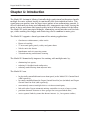
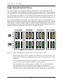
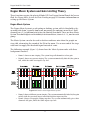
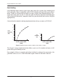
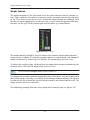
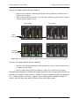
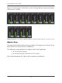
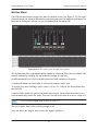
Dan Dugan Sound Design Model E-2 Automatic Mixing Controller User Guide Release Date: August 2013 Version: 1.0 Author: Rob Wenig Important Safety Instructions and Warnings The Model E-2’s circuitry is made in the USA and meets applicable national safety standards. Standards Compliance The third-party power supply provided with this product has been certified to comply with UL. Safety Instructions 1. Read these instructions. 2. Keep these instructions. 3. Heed all warnings. 4. Follow all instructions. 5. Do not use this apparatus near water. 6. WARNING! To reduce the risk of fire or electric shock, do not expose this apparatus to rain or moisture. 7. Clean only with dry cloth. 8. Do not block any ventilation openings. Install in accordance with the manufacturer’s instructions. 9. Do not install near any heat sources such as radiators, heat registers, stoves, or other apparatus (including amplifiers) that produce heat. 10. Do not defeat the safety purpose of the polarized or grounding-type plug. A polarized plug has two blades with one wider than the other. A grounding type plug has two blades and a third grounding prong. The wide blade or the third prong are provided for your safety. If the provided plug does not fit into your outlet, consult an electrician for replacement of the obsolete outlet. 11. Protect the power cord from being walked on or pinched particularly at plugs, convenience receptacles, and the point where they exit from the apparatus. 12. Only use attachments/accessories specified by the manufacturer. 13. Unplug this apparatus during lightning storms or when unused for long periods of time. 14. WARNING! Refer all servicing to qualified service personnel. Servicing is required when the apparatus has been damaged in any way, such as power-supply cord or plug is damaged, liquid has been spilled or objects have fallen into the apparatus, the apparatus has been exposed to rain or moisture, does not operate normally, or has been dropped. 15. WARNING! To reduce the risk of electric shock, DO NOT REMOVE COVER. No user serviceable parts inside. Warranty Statement Warranty: One year parts and labor Dan Dugan Sound Design warrants that Model E-2 hardware will be free from defects in components and workmanship for a period of 12 months from the date of invoice. During the warranty period, Dan Dugan Sound Design will cover the cost of all parts and labor to remedy the defect, or replace products which prove to be defective. Dan Dugan Sound Design is not obliged to honor this warranty if the hardware has failed to be maintained and operated as specified by Dan Dugan Sound Design, in the accompanying documentation, or other than in accordance with industry standards. Defects caused by unauthorized modifications, misuse, negligence, act of God or accident are not covered by this warranty. Software is provided as a convenience, but due to the wide variety of computer systems, cannot be guaranteed to work. This Limited Warranty is exclusive and no other warranty is expressed or implied. Dan Dugan Sound Design does not warrant that Dan Dugan Sound Design software, or any third-party software, is error free. Third party branded or manufactured goods are supplied by Dan Dugan Sound Design with care but without responsibility and subject only to third party suppliers’ warranties. In all other respects Dan Dugan Sound Design is not liable for consequential damages. Dugan Model E-2 User Guide Table of Contents Chapter 1: Introduction ............................................................................................. 9 Dugan Speech System Theory ............................................................ 10 Dugan Music System and Gain Limiting Theory .......................... 11 Model E-2 Modes ..................................................................................... 13 Eight-channel........................................................................................ 13 Twelve-channel..................................................................................... 13 Sixteen-channel ................................................................................... 13 Chapter 2: Quickstart ............................................................................................... 15 Chapter 3: Installation and Configuration .................................................. 17 Rack Mounting .......................................................................................... 17 Power Supply ............................................................................................. 18 System Reset ............................................................................................ 18 Rear Panel I/O Connections................................................................ 19 Analog .................................................................................................. 20 Digital .................................................................................................. 21 Music System Threshold Inputs ........................................................ 21 Linking .......................................................................................................... 22 Patching the Model E-2 as an Insert to your Console .............. 22 Unprocessed Outputs ............................................................................ 22 Mix Matrix Outputs .................................................................................. 23 Connecting the Model CP-2 Control Panel..................................... 23 Connecting to a Computer ................................................................... 24 5 Dugan Model E-2 User Guide Chapter 4: Stand-alone Operation .................................................................... 31 Settings ........................................................................................................ 31 If You Must Use a Pre-fader Insert ................................................... 33 Muting Channels.................................................................................. 33 Pre-listening to Muted Channels ....................................................... 34 Chapter 5: Dugan Control Panel Software................................................. 35 The Top Pane ............................................................................................. 37 Adding Units Manually ........................................................................ 37 Selecting Units to Display .................................................................. 38 Setting Controls ........................................................................................ 38 Naming Units and Channels ................................................................ 39 Channel Pane ............................................................................................ 39 Level Indicator...................................................................................... 40 Bypass .................................................................................................. 40 Channel Modes.................................................................................... 41 Preset .................................................................................................. 42 Channel Groups ................................................................................... 42 Override................................................................................................. 43 Meters .................................................................................................. 43 Weight Controls ................................................................................... 44 Master Pane ............................................................................................... 46 Selecting the Number of Channels ................................................... 47 Reset .................................................................................................. 48 Meters .................................................................................................. 48 System .................................................................................................. 48 Mix Bus Matrix ..................................................................................... 49 Group Master Controls ....................................................................... 50 6 Dugan Model E-2 User Guide Dugan Music System and Gain Limiting......................................... 51 Dugan Music System .......................................................................... 51 Gain Limiting ........................................................................................ 54 Chapter 6: Updates ..................................................................................................... 57 Appendix A: Power-up Commands ...................................................................... 59 System Reset ............................................................................................ 59 Network Reset ........................................................................................... 59 DHCP On ...................................................................................................... 59 Number of Channels Mode .................................................................. 60 Appendix B: Connector Pinouts ........................................................................... 61 Appendix C: Specifications ...................................................................................... 65 7 Dugan Model E-2 User Guide 8 Dugan Model E-2 User Guide Chapter 1: Introduction The Model E-2 Automatic Mixing Controller helps professional audio mixers handle multiple live mics without having to continually ride their individual faders. This signal processor patches into the input insert points of an audio mixing console. It detects which mics are being used and makes fast, transparent cross-fades, freeing the mixer to focus on balance and sound quality instead of being chained to the faders. The Model E-2 tracks unscripted dialogue, eliminating cueing mistakes and late fadeups, while avoiding the choppy and distracting effects common to noise gates. The Model E-2 supports a broad spectrum of live mixing applications: • Conference reinforcement, video trucks • Houses of worship • TV news and sports panels, reality and game shows • Wireless mics for theater • Boardrooms and civic meeting rooms • Teleconferencing and distance learning The Model E-2 dramatically improves live mixing with multiple mics by: • eliminating late upcuts; • reducing PA feedback and studio noise; • reducing comb filtering from adjacent mics. The Model E-2 can: • be physically controlled from its own front panel, or the Model CP-2 Control Panel (sold separately); • be remote controlled from the Dugan Control Panel for Java (included) and Dugan Control Panel for iPad (sold separately); • conveniently connect multiple devices via four network ports; • link with other Dugan automatic mixing controllers to create a larger system; • partition channels into one to three groups that can span linked units; • create separate linked systems that do not interact (i.e., for separate studios). 9 Dugan Model E-2 User Guide Dugan Speech System Theory The Dugan Model E-2 Automatic Mixing Controller uses the Dugan Speech System™, a patented and trademarked automatic mixing function. The Dugan Speech System distributes the gain of one open microphone over the entire system, maintaining a natural one-mic ambience. It is essential to distinguish this behavior from the annoying fluctuation of levels and uneven ambience in a conventional gating system. The system automatically manages any number of live mics in unpredictable dialogue situations. When one person speaks, that mic’s gain fades up instantly, and the others down. When the speaker pauses, all mics fade to medium gains that sum to equal one mic at full gain. The result sounds like passing one mic around among the speakers. When several people talk at once, the gain is shared. Figure 1-1 Four snapshots of a three-mic system Figure 1-1 shows the Speech System in action with a three-mic system. • The first frame shows no one speaking; the sound levels at all mics are low. The system fades all channels to medium gains that sum to the equivalent of one mic at full gain. • The second frame shows one person speaking. The system automatically fades his/ her gain to full, while the other two inputs are turned down. • The third frame shows a different person speaking. The system automatically fades his/her gain to full, while the other two inputs are turned down. • The fourth frame shows two people speaking simultaneously. The system automatically shares the gain between them, while the other input is turned down. 10 Dugan Model E-2 User Guide Introduction Dugan Music System and Gain Limiting Theory These functions require the physical Model CP-2 or Dugan Control Panels for Java or iPad. See Dugan Music System and Gain Limiting on page 51 for more information on setting up the Music System. Dugan Music System The Dugan Music System is a soft-gating or ducking system with its threshold set by an audio side-chain, typically from a mic measuring the ambient sound level. Each channel has a 2:1 expansion ratio below the floating threshold. There are three Music System Threshold inputs on the AUDIO I/O 9–12 connector (channels 9–11), one for each group. The Music System can also be used to duck an audience mix when the people on stage talk, attenuating the sound of the PA in the room. Use an aux send of the stage vocal mix to supply the threshold signal instead of a mic. The following example (Figure 1-2) shows how the Music System works with three background vocalists. • Frame 1 shows no one singing. The system keeps all channels at a low gain. • Frame 2 shows one person singing. The system automatically fades his/her gain to full, while the other two inputs stay low. Figure 1-2 Function of the Dugan Music System • Frame 3 shows a different person singing. The system automatically fades his/her gain to full, while the previous singer’s mic and the other input stay low. • Frame 4 shows two people singing together. The system automatically gives their channels full gain, while the other input stays low. 11 Dugan Model E-2 User Guide Gain Limiting Gain Limiting reduces master gain as new mics enter the system, thus avoiding feedback and noise. This is commonly called NOM (Number of Open Mics) gain adjustment. Unlike NOM functions on other systems, Dugan Gain Limiting doesn’t just count how many mics are on. It sums the gains of all active channels (including partially attenuated channels), compares them to a gain threshold, and reduces the gain appropriately. Conventional automatic mixing implementations always assume an NOM of 1. 10 8 6 Gain Reduction (dB) 4 4 2 Gain Reduction (dB) 2 0 0 2 4 6 0 8 0 2 4 6 8 Number of Open Mikes (NOM) Number of Open Mikes (NOM) Figure 1-3 NOM and gain reduction: NOM =1 (left); NOM = 4 (right) The Dugan’s unique implementation allows you to set the number of mics at full gain before gain limiting occurs. For example, if there is enough gain before feedback to tolerate four open mics, the gain limit can be set to 4. Gain reduction begins when the fifth mic turns on. 12 Dugan Model E-2 User Guide Introduction Model E-2 Modes The Model E-2 is an eight-channel audio processor offering three Dugan algorithms. However, it can operate in twelve- or sixteen-channel modes with reduced features. See Chapter 3: Installation and Configuration to learn how to choose a mode with the #ch button during installation. Eight-channel • The Dugan Speech System™ provides automatic mixing for eight live mics. • The Dugan Music System™ offers automatic downward expansion to help reduce feedback and bleed in live music performances (i.e., opera, background vocals). Thresholds are adjusted automatically by monitoring ambient noise levels. • Dugan Gain Limiting™ monitors the number-of-open-mics (NOM) and adjusts the master gain to prevent feedback or ambient noise build-up. Dugan Gain Limiting should be used with the Dugan Music System to reduce feedback and noise. It can perform the same functions when mics are switched on and off manually. • Linking creates one large automatic mixing system with multiple Dugan units. • An internal mix bus matrix routes processed or unprocessed inputs to four mix bus outputs. • Unprocessed outputs are provided: analog inputs are mirrored at the digital output, and vice versa. This provides convenient pre-processing signals for multitrack recording. Twelve-channel • The Dugan Speech System™ provides automatic mixing for twelve live mics. • Linking creates one large automatic mixing system with multiple Dugan units. Sixteen-channel • The Dugan Speech System™ provides automatic mixing for sixteen live mics. This is a digital connection that uses both the AUD and LINK ADAT optical connectors. 13 Dugan Model E-2 User Guide 14 Dugan Model E-2 User Guide Chapter 2: Quickstart This section provides step-by-step instructions to help you get started quickly using the Dugan Speech System to mix up to eight channels. Twelve- and sixteen-channel I/O is available using the Dugan Control Panel software. See Chapter 5: Dugan Control Panel Software to learn about these options. 1. Connect the provided power supply to the Model E-2. 2. Hold the channel 1 bypass button down and power up the unit. Keep holding the bypass button down for three seconds until the unit finishes booting. This System Reset command sets all parameters to factory default settings and clears label text. We recommend executing a System Reset before starting a new installation. This is just like zeroing a console before a show. 3. Set the NORM-SLAVE switch on the rear panel to NORM (up) for unlinked operation. The Model E-2 can be interfaced using balanced analog or digital optical connectors: 4. Analog: Move the ANA-DIGI switch on the rear panel to the ANA (up) position. The DB25 connectors carry balanced analog signals. Each connector provides four inputs and four outputs. Figure 2-1 Model E-2 rear panel Digital: Move the ANA-DIGI switch on the rear panel to the DIGI (down) position, connect the console ADAT output to AUD IN, and connect AUD OUT to the console’s ADAT input. 5. Whenever possible, route each Model E-2 channel as a post-fader, pre-compressor insert to each mic channel. 15 Dugan Model E-2 User Guide stays lit green Figure 2-2 Setting console preamp gain 6. With the room quiet, raise your console preamp gains until the Model E-2’s green level LEDs stay illuminated. The level LED illuminates green when the input level is within the acceptable range for automatic mixing and flashes red to indicate clipping. There should be enough gain ahead of the Model E-2 to maintain the green LED at all times. NOTE: When the green level light extinguishes, the channel is in a downward expansion mode to avoid feedback. This condition should be avoided because the smooth ambience that characterizes Dugan automatic mic mixing is lost. Figure 2-3 During ambience with 4 mics, auto mix gain displays should hover around -6 dB 7. Adjust your console’s preamp gains so all LED meters float at about the same gain when no one is talking. This procedure assures smooth automatic mixing. 16 Dugan Model E-2 User Guide Installation and Configuration Chapter 3: Installation and Configuration We recommend placing the Model E-2 in a convenient place in the engineer’s line of sight. Figure 3-1 Model E-2 placed conveniently Rack Mounting All E-Series Dugan controllers are a half-rack wide, so one or two can be mounted in a single rack space. Each unit ships with one long and one short rack ear and one joining plate. The rack ears for older E-Series Dugans differ slightly from the current design, but the joining plates are the same. All E-Series Dugans can be mounted side-by-side using the appropriate rack ear for each unit. To mount one unit: Attach one long and one short rack ear, then mount in the rack. To mount two units side-by-side: 1. For the left unit, remove the four screws from the right side of the top and bottom lids. 2. Attach the top and bottom joining plates to the left unit. 3. For the right unit, remove the four screws from the left side of the top and bottom lids. 4. Attach the top and bottom joining plates to the right unit. 5. Attach the appropriate rack ears to the left and right units. 6. Mount the pair in the rack. 17 Dugan Model E-2 User Guide Power Supply Units shipped to the USA include a 12 V, 1.5 A, 120 VAC power supply. Contact the factory if you require a different power supply. In an emergency, the Model E-2 can accept power supplies within the following ranges: • 12–24 VDC, either polarity, 1.5 A • 9–18 VAC, 1.5 A System Reset Hold down the channel 1 bypass button and power up the unit. Keep holding the bypass button down for about three seconds until the unit finishes booting. This System Reset command restores all parameters to factory default settings and clears label text. This is just like zeroing a console before a show. We recommend executing a System Reset before starting a new installation. The Model E-2 can execute four other power-up commands (see Appendix A: Powerup Commands). NOTE: If for any reason you cannot connect to a computer, power-up commands can establish essential settings. 18 Dugan Model E-2 User Guide Installation and Configuration Rear Panel I/O Connections The Model E-2 provides the following rear panel I/O connectors: • AUDIO I/O 1–4 • AUDIO I/O 5–8 • AUDIO I/O 9–12 Each DB25 connector carries four input and four output analog channels. All analog audio connections are balanced. To connect with XLR connectors, use readily available adapter squids. Although the Model E-2 uses these connectors for analog I/O, they are wired according to the TASCAM digital standard. • AUD IN, AUD OUT These ADAT connectors carry eight audio I/O channels. • LINK IN, LINK OUT These ADAT connectors carry proprietary linking data. They can also be re-assigned as eight additional audio channels. • CP-2 CONTROL PANEL This carries RS422 data to and from the Model CP-2 Control Panel. Figure 3-2 Model E-2 rear panel I/O connectors 19 Dugan Model E-2 User Guide Analog Move the ANA-DIGI switch to ANA (up position). If you do not need the Dugan Music System, twelve channels of automixing are available using all three DB25 connectors. The content of the AUDIO I/O 9–12 DB25 connector depends on the state of the #ch switch. This can be set in the Dugan Control Panel (see Chapter 4: Dugan Control Panel) or with a power-up command (see Appendix A: Power-up Commands). +4/-10 This sets the input sensitivity, internal headroom, and output level between professional (+4) and consumer (-10) audio line levels. 8-Ch • Eight automix channels on the AUDIO I/O 1–4 and AUDIO I/O 5–8 DB25 connectors • Three Music System threshold inputs on the AUDIO I/O 9–12 (channels 9–11) Channel 12 is an auxiliary input sent to the mix bus matrix. • Four mix bus outputs on AUDIO I/O 9–12 (channels 9–12) • Linking available on LINK IN, LINK OUT • Unprocessed outputs are available on AUD OUT NOTE: Since relays route the audio input signals for channels 1–12 directly to their respective outputs when the unit is off, you can leave it patched when not in use. 12-Ch • Twelve automix channels on all three DB25 connectors • Linking available on LINK IN, LINK OUT • Music System and mix buses not available 20 Dugan Model E-2 User Guide Installation and Configuration Digital Move the ANA-DIGI switch to the DIGI (down) position. This switches the I/O to the ADAT connectors. The state of the #ch switch determines the I/O count and linking capability. This can be set in the Dugan Control Panel (see Chapter 4: Dugan Control Panel) or with a power-up command (see Appendix A: Power-up Commands). 8-Ch • Channels 1–8 on AUD IN/AUD OUT • Linking and Music System available The Music System threshold inputs are still input as analog signals on AUDIO I/O 9– 12 (channels 9–11). • Mix bus outputs available on AUDIO I/O 9–12 (channels 9–12) • Unprocessed outputs are available on AUDIO I/O 1–4 and AUDIO I/O 5–8 • Channels 1–8 on AUD IN/AUD OUT • Channels 9–16 on LINK IN/LINK OUT • Dugan Music System, input splits, mix bus outputs, and linking not supported 16-Ch Music System Threshold Inputs A Music System threshold signal can be provided as a reference for each group. When the levels of channels in the group exceed the level of the Music System threshold signal, the channels come up to full gain. The sensing mics are typically input to the same console as the program mics, but are routed to direct outputs or sends, not mix buses. The AUDIO I/O 9–12 DB25 connector can receive three Music System threshold inputs, one for each group (a, b, c on channels 9, 10, 11). 21 Dugan Model E-2 User Guide Linking Up to eight Dugan units can be linked into a single automatic mixing system. The audio I/O for each must be configured and connected individually. Linking passes only control information between Dugans, not audio. One unit must be set to be the master and the others slaves. 1. Designate one unit as the master by setting the NORM–SLAVE switch on the rear panel to NORM (up). 2. Designate any other units as slaves by setting their NORM–SLAVE switches on the rear panel to SLAVE (down). 3. Use ADAT (Toslink) cables to link units in a ring network (see above). Note that all LINK IN and OUT connectors are used to create the ring. Figure 3-3 Linking Dugan units Patching the Model E-2 as an Insert to your Console The best place to insert the • Dugan Speech System channels is post-EQ, post-fader, pre-compressor; • Dugan Music System channels is post-EQ, pre-fader, pre-compressor. Unprocessed Outputs When using the ANA setting, the ADAT AUD OUT connector can send unprocessed signals (channels 1–8) to a multitrack recorder. When using the DIGI setting, the AUDIO I/O 1–4 and AUDIO I/O 5–8 connectors can send unprocessed signals (channels 1–8) to a multitrack recorder. 22 Dugan Model E-2 User Guide Installation and Configuration Mix Matrix Outputs In eight-channel mode, an internal mix matrix can route processed or unprocessed inputs to four mix bus outputs on the AUDIO I/O 9–12 connector. For more information on using mix buses, see Mix Bus Matrix on page 49. Connecting the Model CP-2 Control Panel The Dugan Model CP-2 Control Panel hardware can be connected to the four-pin mini-XLR connector. When a CP-2 is connected, the channel weight and master NOM gain limit, music system threshold, and automix depth values can be set only on the CP-2 and are read-only on the Dugan Control Panels for Java and iPad. Figure 3-4 Model CP-2 Control Panel 23 Dugan Model E-2 User Guide Connecting to a Computer Two Java applets are provided with the Model E-2: • The Dugan Utility helps you connect to a network. It is also used to update the firmware (see Chapter 6: Updates). • The Dugan Control Panel offers expanded operational capabilities. Insert the USB thumb drive (or CD) supplied with the Model E-2, or download the latest version from: http://www.dandugan.com/downloads - OR http://tech.groups.yahoo.com/group/duganusers/files/ To connect the Model E-2 directly to a computer, use the rear panel Ethernet jack. An older PC may require a crossover cable. Use a straight Ethernet cable to connect to a network. We strongly recommend that Windows users turn the Windows firewall off. The Windows Firewall blocks port 9776 used by the Dugan software to communicate. If you must leave the Windows firewall on, either open this port or use the workaround described in Connecting when Windows Firewall is On on page 29. We recommend turning off the computer’s WiFi during this process because it sometimes interferes. You can turn it back on after the connection has been established. For those who wish to set a specific IP address, proceed to Software Configuration for a Specific IP Address on page 28. 24 Dugan Model E-2 User Guide Installation and Configuration Establishing Network Connections iPad We recommend using a computer to complete your network connection before using the iPad app. 1. Launch Dugan-Utility-yyyymmdd.jar. Figure 3-5 Dugan Utility 2. Wait a minute and if the list pane is blank, click Refresh List. If the list pane remains blank, proceed to Manually Add Unit below. If the list pane displays Dugan units, continue. 3. Click on the first unit in the list so it is highlighted. The Network Parameters section displays information about that unit. If Unit Reachable is YES, you are ready to use the Dugan Control Panel with that unit. If you have additional Dugan units to connect, select the next unit in the list and repeat this step. If you are finished with installation, proceed to Chapter 4: Dugan Control Panel. If Unit Reachable is NO, proceed to the next step. 4. Power down the Model E-2. 25 Dugan Model E-2 User Guide 5. Hold down the channel 1 mute button during the entire power up sequence. This resets all network parameters to their factory default values. Power up is finished when all LEDs stop flashing. 6. Click Refresh List. 7. Click on the first unit in the list so it is highlighted. If Unit Reachable is YES, you are ready to use the Dugan Control Panel with that unit. If you have additional Dugan units to connect, select the next unit in the list and repeat Step 3. If you are finished with installation, proceed to Chapter 4: Dugan Control Panel. If Unit Reachable is NO, proceed to the next step. 8. Select the Use DHCP parameter. 9. Click Send New Params to Unit. 10.Click Refresh List. 11.Highlight the unit in the list pane again. If Unit Reachable is YES, this unit is ready to use with the Dugan Control Panel. If you have additional Dugan units to connect, select the next unit in the list and repeat Step 3. If you are finished with installation, proceed to Chapter 4: Dugan Control Panel. If Unit Reachable is NO, proceed to the next step. 12.De-select the Use DHCP parameter. 13.Copy This Computer’s IP Address to the IP Address field, and increase the value in the last (fourth) group by one. For example, if This Computer’s IP Address is 192.168.1.101, set IP Address to 192.168.1.102. 14.Click Send New Params to Unit. 15.Click Refresh List. 16.Highlight the unit in the list pane again. If Unit Reachable is YES, this unit is ready to use with the Dugan Control Panel. If you have additional Dugan units to connect, select the next unit in the list and repeat Step 3. If you are finished with installation, proceed to Chapter 4: Dugan Control Panel. If Unit Reachable is NO, see Using the Internally Stored Dugan Control Panel on page 27. 26 Dugan Model E-2 User Guide Installation and Configuration Manually Add Unit If the Dugan unit does not appear in the Dugan Utility list pane, you can manually add the unit: 1. Power down the Model E-2. 2. Hold down Channel 1’s mute button and power up the unit. This performs a network reset. 3. Click Manually Add Unit. 4. Enter the default IP address: 192.168.1.xx xx = last two digits of serial number, unless they are 00, in which case enter 100. 5. Click OK to exit the dialog. 6. Click Refresh List. If the list pane is still blank, see below. Using the Internally Stored Dugan Control Panel Normally, the Dugan Control Panel is run from the Dugan-Control-Panel-vxxx.jar file. However, if for any reason you do not have that file or an Internet connection, you can run the Dugan Control Panel from a copy stored in the unit. iPad It is not currently possible to run the internally stored Dugan Control Panel from an iPad. To run the internally stored Dugan Control Panel: 1. Launch your browser. 2. Enter the IP Address of the unit. ‘ If you do not know the IP Address, continue 3. Hold down Channel 1’s mute button and power up the unit. This performs a network reset, which sets a default IP address: 192.168.1.xx xx = last two digits of serial number, unless they are 00, in which case enter 100. 4. Enter this address in your browser. If you still cannot connect the device to your computer, consult the duganusers Yahoo group (http://tech.groups.yahoo.com/group/duganusers) or contact Dan Dugan Sound Design. 27 Dugan Model E-2 User Guide Software Configuration for a Specific IP Address This section explains to users with IT expertise how to set a specific IP address for any Dugan unit on the network. 1. Launch Dugan-Utility-vxx.jar. Figure 3-6 Dugan Utility 2. Wait a minute and if the list pane is blank, click Refresh List. If the list pane remains blank, skip back to Manually Add Unit above. If the list pane displays Dugan units, continue. 3. Click on the first unit in the list so it is highlighted. The Network Parameters section displays information about that unit. 4. If Use DHCP is selected, de-select it. 5. Enter the desired IP address into the IP Address field. 6. Click Send New Params to Unit. The Model E-2 will reboot. 28 Dugan Model E-2 User Guide Installation and Configuration Connecting when Windows Firewall is On The Windows Firewall blocks access to port 9776, which is used by the Dugan software. If you must leave the Windows Firewall on, you can operate the Dugan Control Panel in a browser window. Enter the Model E-2’s IP address directly in the browser’s address field. The browser uses the Dugan Control Panel that is stored in the Model E-2’s hardware, not the version that you may have downloaded to your computer. 29 Dugan Model E-2 User Guide 30 Dugan Model E-2 User Guide Chapter 4: Stand-alone Operation This chapter tells you how to operate the Model E-2 stand-alone (i.e., without the physical Model CP-2 Control Panel or the software Dugan Control Panel for Java or iPad). Settings 1. Put all the live mic channels in automatic mixing mode by deactivating bypass and mute. 2. Activate the mute buttons for all unused channels. Figure 4-1 Channel controls 3. Using a normal speaking voice, adjust the console input trim controls to the highest possible gain without clipping. The input gain to the Model E-2 should be high enough keep the level LED lit green during silences. If the input trim controls do not provide enough level, set the +4/-10 switch to the -10 position. If the preamp gain controls are set too low, the inputs drop below their minimum operating level. This causes downward expansion to prevent feedback but the smooth ambience is disrupted. stays lit green Figure 4-2 Setting console preamp gain 31 Dugan Model E-2 User Guide 4. Set the console faders to your normal operating positions. 5. Balance the preamp gain controls so the fluctuating ambient noise registers equally on the Model E-2’s meters. Note that raising the preamp gain of one channel causes its gain to rise and the others to fall; it’s a balancing act. When balanced, all mics have equal access to the system gain. 6. If clipping occurs because someone speaks louder than expected, turn down all of the console’s input trim controls the same amount, and raise the console master to compensate. This procedure maintains the ambient noise balance required for optimal automatic mixing. A better method uses the weight controls provided by the Model CP-2 or Dugan Control Panels for Java or iPad. See Chapter 5: Dugan Control Panel Software. Figure 4-3 During ambience with 4 mics, auto mix gain displays should hover around -6 dB Figure 4-4 During ambience with 8 mics, auto mix gain displays should hover around -9 dB TIP: To eliminate an unwanted noise in the mix, use the gain displays to locate the offending channel and activate its mute button. 32 Dugan Model E-2 User Guide Stand-alone Operation If You Must Use a Pre-fader Insert The Dugan Speech System is more convenient to operate if patched post- rather than pre-fader. If your console allows this, skip this section. If you use a pre-fader insert, this section describes how to properly mute and pre-listen to muted channels. Muting Channels Mics must be muted by using the Dugan’s mute buttons. Pulling a fader down on the console will not properly mute a channel. Although that mic is no longer audible in the mix, it still contributes to the gain computations and causes ambient noise fluctuation. In the worst case, this could cut off a speaker. Dugan Control System Gain Control Console Microphone Input Insert Point A EQ Mix Bus Insert Point B Fader Insert Point C Figure 4-5 Insert points on most analog mixers are at point B To properly mute a channel: • Leave the console faders up, adjust levels while people are talking, and mute a mic by pressing the Dugan’s mute mode button. Enable the mic when needed by deactivating the mute button. Muting mics does not alter the overall ambient sound mix: the Speech System compensates by slightly raising the ambient gains of the other mics to compensate for the gain subtracted by muting a mic. Note that this behavior is during ambience without input to any mic; while one or more mics receive speech input, the gain shifts to the active mics. - OR - • Use the bypass switch with the console fader pulled down. This keeps the mic instantly available on the fader but that channel is no longer in the control mix. Be aware that bypass may generate a click if it interrupts room rumble, whereas the mute button does a quick-fade. The mute button can be used with the fader up; bypass is best used with the fader down. 33 Dugan Model E-2 User Guide Pre-listening to Muted Channels If your console allows listening to a mic before the insert point, you can mute on the Dugan. If signal through the Dugan is required to pre-listen to a mic, pull the fader down and put the channel in bypass mode. When your mic check is done, switch the channel back to auto mode, and raise the fader so the Dugan can cue in the mic. 34 Dugan Model E-2 User Guide Chapter 5: Dugan Control Panel Software The Dugan Control Panel software has both Java and iPad versions. This chapter discusses the Java version and notes the iPad app’s few differences. NOTE: After configuring settings with the Dugan Control Panel, it can be disconnected. All settings are retained and the unit continues to function on its own. The Dugan Control Panel provides additional controls and features not available from the hardware front panel: • Channel weight control • Channel man mode to bypass automixing with a soft switch • Eight, twelve, and sixteen channel I/O modes • Dugan Music System and Gain Limiting • Groups a, b, and c • Unit and channel naming • Preset function to recall favorite settings • Override function to solo a mic • Master mute function • Four auxiliary outputs from a mix bus matrix • Input and output level meters 35 Dugan Model E-2 User Guide Figure 5-1 Dugan Control Panel Launch the Dugan-Control-Panel-vxxx.jar. If this file is not available and you have an Internet connection, you can obtain the latest version from: http://www.dandugan.com/downloads - OR http://tech.groups.yahoo.com/group/duganusers/files/ If you do not have an Internet connection, you can use the version of the Dugan Control Panel stored inside the unit’s firmware. See Using the Internally Stored Dugan Control Panel on page 25. The Dugan Control Panel has three panes. The controls displayed in these panes depend on which Dugan device is selected in the Top Pane. Top Pane icons for all connected Dugan units Channel Pane man, auto, mute, preset, override, group, weight, bypass, and channel name controls Master Pane OVERRIDE, PRESET, MUTE, meters, system, and reset controls 36 Dugan Model E-2 User Guide Dugan Control Panel Software The Top Pane The Top Pane displays all connected Dugan units. The selected unit is enclosed by a yellow rectangle. Click on another unit to select it and deselect the previous unit. Figure 5-2 Top Pane If all connected units do not appear in the Top Pane, see Establishing Network Connections. To display a unit’s IP address, hover the mouse over the unit’s name. iPad To display a unit’s IP address, touch and hold the unit’s name. Adding Units Manually To add a unit manually with a known IP address, click the + sign at the right of the Top Pane and enter the IP address in the dialog that appears. To add a unit manually without a known IP address: 1. Power down the Model E-2. 2. Hold down Channel 1’s mute button and power up the unit. This sets a default IP address: 192.168.1.xx. xx = last two digits of serial number, unless they are 00, in which case enter 100. 3. Click the + sign at the right of the Top Pane. 4. Enter the default IP address. 5. Click OK to exit the dialog. To display a unit’s IP address, hover the mouse over the unit’s name. 37 Dugan Model E-2 User Guide Selecting Units to Display The Dugan Control Panel finds all available units connected to the network automatically. Some facilities have multiple studios on the same network that operate independently. In that case, you may want to restrict the units shown in the Top Pane to those in your studio. To do this: 1. Hover the mouse cursor over the names of the units that you want to display, and note their IP addresses. 2. Ctrl-click on the + sign at the right of the Top Pane. The + sign turns red. 3. Quit and relaunch the Dugan Control Panel. It opens with Auto Detect Disabled in the Top Pane 4. Click on the red + sign, and enter the IP address of the first unit you want to add. 5. Repeat step 4 until your units all appear in the Top Pane. Manually added units must also be removed manually. To remove manually added units from the Top Pane, shift-click on the + sign. A dialog appears to confirm that they have been removed. To restore automatic detection, Ctrl-click on the + sign, which turns white. Setting Controls Controls can be adjusted five ways: • Enter a dB value in the numeric field. • Drag in the numeric field (not on iPad). When a slider is present: • Drag the slider up or down. • Click in the slider track to raise or lower the value by 0.5 dB. • Ctrl-click anywhere on the slider to reset its value to 0 (touch and hold on iPad). 38 Dugan Model E-2 User Guide Dugan Control Panel Software Naming Units and Channels Connected units are displayed in the top pane in alphabetical order. Use names with number prefixes if you wish to display them in your own order. To name a unit and its channels: 1. Select a unit in the top pane. 2. Select the yellow text in the right pane (under the Dugan logo) and type a name. 3. Press the Enter key on the keyboard to set the name. 4. To name a channel, select the yellow text and type a name. 5. Press the Enter key on the keyboard to set the name. Channel naming is cleared by pressing reset (see page 48). Channel Pane The Channel Pane contains the controls and indicators for each channel. Channels are always in one of three modes: man, auto, or mute. The active channel mode illuminates. All transitions are made with a smooth, rapid fade. Select a channel mode by pressing the individual mode buttons or the Master PRESET button. Figure 5-3 shows a typical system: channels 1–4 in auto with ambient noise, and channels 5–8 in mute. Figure 5-3 Channel Pane 39 Dugan Model E-2 User Guide Level Indicator Each channel has a level LED that lights green when the audio level is adequate for automatic mixing. It should remain green when no one is talking. • If the level indicator blinks, raise the console’s channel input gain, and/or move the +4/-10 switch on the rear panel to -10. • If the level LED lights red, lower the console’s channel input gain and/or move the +4/-10 switch on the rear panel to +4 until it stays green at all times. Bypass When bypass is active, the signal passes through without A/D and D/A conversion or automixing. A bypassed channel appears inactive, with all lights extinguished. Figure 5-4 bypass button lit Man and bypass modes are similar: • bypass makes an instantaneous transition, which can cause an audible click. It is a hardware bypass and therefore has no signal latency. • man performs a quick fade without sonic artifacts. It has the same signal latency as auto mode. Since analog channels 1–12 are bypassed when the power is off, it is not necessary to unpatch the Model E-2 if not in use. To deactivate bypass, you can: • Click bypass again; - OR - • Click any of the three channel mode buttons. 40 Dugan Model E-2 User Guide Dugan Control Panel Software Channel Modes There are three channel modes: man, auto, and mute. Changing modes initiates a half-second fade to the new mode. Like radio buttons, you can only choose one mode at a time. Figure 5-5 Channel modes Man In man mode there is no automixing, and the signal passes through at unity gain. Even though man and bypass modes perform similar functions, we recommend using man during live mixing to prevent clicks. Auto This is the normal Dugan automixing mode. Mute The channel is muted when mute is active. 41 Dugan Model E-2 User Guide Preset Use the Preset function to store your favorite channel mode settings, which may be restored by pressing the Master PRESET button. When the unit powers up, the channels default to their preset modes. To set channel presets: 1. Click the channel preset button next to the desired channel mode button. 2. For all unused channels, click the preset button next to the mute button. channel preset buttons Master PRESET button Figure 5-6 Channel preset (left) and Master PRESET (right) buttons The preset indicators should mirror your normal working combination of input modes. The normal condition can then be restored by pressing the Master PRESET button. Channel Groups Each channel can be assigned to one group: a, b, or c. Each group functions as a separate, independent automatic mixer that can span multiple linked Dugans. Channels assigned to groups need not be contiguous. Applications where groups are helpful include: • Separate Rooms: Assign the mics in each room to different groups so they function as separate automatic mixers. • Stereo Panning: Assign the mics panned left, right, and center to groups a, b, and c, respectively, to maintain a stable stereo ambience. To assign a channel to a group, click the group button until the desired group letter appears. The channel strip background is tinted green (group b) or blue (group c); group a is not tinted (Figure 5-7). A set of OVERRIDE, PRESET, and MUTE buttons appears in the Master Pane for each group. 42 Dugan Model E-2 User Guide Dugan Control Panel Software Figure 5-7 Channels in three groups Override Override can be used to instantly mute all mics except one (the host or chairperson). However, any number of mics can be included in the override group. It can thus be used to make a dramatic A/B comparison between automatic and conventional mixing. To assign channels to an override group, activate the override button on each channel. Pressing the Master section OVERRIDE button puts channels with their override buttons lit into man mode. All other channels are muted. Press the OVERRIDE button again to restore normal automixing operation. Meters The meters have three display modes. Table 5-1 Meter modes Meter Displays Meter Color auto mix gain action of the Dugan Speech System green input input level yellow output output level blue The default meter display is auto mix gain. This is the most useful choice during normal operation; the input and output meters are only used when setting or checking levels. Click on the Master meters button to toggle through the three meter display modes. 43 Dugan Model E-2 User Guide Weight Controls The weight controls set the side-chain levels for each channel into the control system. This establishes the relative sensitivity of the automatic mix for the channels in use. They do not change the mix levels. When the weight controls are balanced, each mic has an equal opportunity to take over the system: when one person talks into one mic, he/she gets all the auto mix gain and the others get turned down. Figure 5-8 Weight controls The weight controls should be used to balance the channel auto mix gain indicators when no one is talking. If a console preamp trimmer is turned down, that channel’s weight control can be turned up to re-balance the automixing, and vice-versa. To adjust the weight setting, click and drag the weight slider or enter a number in the numeric field. Ctrl-click the weight slider to reset it to 0. iPad Touch and hold the weight slider to reset its value to 0. It is important to understand that weight does not set that mic’s level in the mix when that person speaks, but only its sensitivity in activating automatic mixing. The Speech System detects the ratios of the levels between channels, not their absolute levels. The weight control is not a gate threshold! The following example illustrates how weight affects auto mix gain (see Figure 5-9). 44 Dugan Model E-2 User Guide Dugan Control Panel Software Raising the weight control for one channel: • increases that channel’s auto mix gain display during ambience and decreases it slightly for the others; • makes it more difficult for others to speak when someone speaks into the channel with the higher weight setting. higher weight lower weight same input levels resulting auto mix gains Figure 5-9 How changing one channel’s weight control during ambience affects the auto mix gains Lowering the weight control for one channel: • decreases the auto mix gain display during ambience for that channel and increases it slightly for the others; • makes it more difficult for that channel’s talker to be heard over the others. For optimal performance, balance the weight controls so the channel gains display approximately equally when no one is talking. If there is ongoing noise near one mic (e.g., computer fan or air vent), suppress it by reducing that channel’s weight. Of course, you will hear that noise increase when that talker speaks. 45 Dugan Model E-2 User Guide Figure 5-10 shows eight- and four-mic systems with appropriate auto mix gain displays when no one is talking. Figure 5-10 Multiple mic ambience: auto mix gain hovers around -9 dB for eight mics, -6 dB for four mics Master Pane The content of the Master Pane changes to reflect the Dugan device selected. In the figure below, the selected device is a Model E-2. The following version numbers are displayed below the Dugan logo. • the selected unit’s firmware • the currently running Control Panel (CP-J) software This section documents the Master Pane’s controls and indicators. 46 Dugan Model E-2 User Guide Dugan Control Panel Software Figure 5-11 Master Pane: Analog settings (left), Digital settings (center), Music System controls (right) The Master indicators are: • online: lights when the unit is connected to the Dugan Control Panel. • analog/digital, master/slave, +4/-10: show their rear panel switch settings. The Master controls, located on the far right, include #ch, reset, meters, system, mix bus, OVERRIDE, PRESET, and MUTE. A set of OVERRIDE, PRESET, and MUTE buttons appears for each active group. Each control is discussed below. Selecting the Number of Channels The state of the rear panel ANA-DIGI switch determines the number of possible channels. Press the #ch button to toggle between the two available values: • ANA: 8 or 12 • DIGI: 8 or 16 See Rear Panel I/O Connections on page 19 for a full explanation of these options. 47 Dugan Model E-2 User Guide Reset Press the reset button to restore the unit to its default settings. Meters Click on the meters button to toggle through the three meter display modes. Table 5-2 Meter modes Meter Displays Meter Color auto mix gain action of the Dugan Speech System green input input level yellow output output level blue System When multiple Dugan units are linked, groups a, b, and c can span linked units. Groups operate as independent automatic mixers, and do not have to use contiguous channels. It is possible to have multiple systems of linked units on your network (i.e., separate studios on the same network). These units will all appear in the top pane. The Model E-2 allows up to 16 separate systems on a network. To separate multiple systems: 1. Select the first unit to include in the system by clicking it in the top pane. 2. Click the system button and select a unique number for that system. 3. Repeat for each unit in that physically linked system, making sure to use the same number for each unit in the system. 4. Repeat steps 1–3 for each system. 5. To query which system a unit belongs to, select it in the Top Pane and view its number on the system button. To control which units are displayed in the Top Pane, see Selecting Units to Display on page 38. 48 Dugan Model E-2 User Guide Dugan Control Panel Software Mix Bus Matrix Click the mix bus button to open the mix bus matrix screen (see Figure 5-12). In eightchannel mode, an internal mix matrix can route processed or unprocessed inputs to four mix bus outputs (aux out 1–4) on the AUDIO I/O 9–12 connector. Figure 5-12 Mix bus matrix screen in Dugan Control Panel The default mix bus assignment routes automix 1–8 to out 9. You can re-establish the default routing by clicking the set to defaults button (at top-left). Scroll horizontally to see all available processed and unprocessed signals. A blank cell means no connection. A cell with 0.0 means unity gain. To assign your own routings, enter values (-96 to +31.5 dB) in the desired mix bus matrix cells. A master fader trims the gain of each mix bus output. Gain values may also be entered numerically below the fader. You can Ctrl-click the fader to reset its value to 0. iPad Touch and hold the gain slider to reset its value to 0. The level meter shows the resulting output level. You can mute the output and reverse the signal’s polarity. 49 Dugan Model E-2 User Guide Group Master Controls The Master Pane displays a set of group master control buttons for each group in use. Override Activating the Master OVERRIDE button has the following effect on individual channels: • Channel override button active: puts the channel in man mode with full gain (no automixing); - OR - • Channel override button inactive: mutes the channel. De-activating the Master OVERRIDE button returns the channels to normal operation. Select channel(s) to include in the override group by activating their override button(s). Remove channel(s) from the override group by deactivating their override button(s). Preset Clicking the Master PRESET button sets the channel modes (man, auto, mute) to those shown on each channel’s preset buttons. Use these settings to store your favorite channel mode settings. When the unit powers up, the channels default to their preset modes. Mute Click the MUTE button to mute a group. Click it again to unmute the group. 50 Dugan Model E-2 User Guide Dugan Control Panel Software Dugan Music System and Gain Limiting These functions require the physical Model CP-2 or Dugan Control Panels for Java or iPad. Dugan Music System The Dugan Music System is a soft-gating or ducking system with its threshold set by an audio side-chain, typically from a mic measuring the ambient sound level. Each channel has a 2:1 expansion ratio below the floating threshold. There are three Music System Threshold inputs on the AUDIO I/O 9–12 connector (channels 9–11), one for each group. Consider the following before placing the sensing mic: • Place the sensing mic in the same area, and pointing in the same direction as the program mics. This samples, as closely as possible, the ambient sound picked up by the program mics. • Use the same type of mic for program and sensing applications. • Do not place the sensing mic close to an individual voice or instrument. • Do not point the sensing mic at a pit orchestra. • Do not put the sensing mic in the back of the house because of the time delay. Patch the preamplified sensing mic to input 9, 10, or 11 (group a, b, or c) on the AUDIO I/O 9–12 connector. The direct output of a console input strip is typically used, with the mix buses deselected. Set the console input gain for the sensing mic 10–15 dB higher than the program mics. The Music System can also be used to duck an audience mix when the people on stage talk, attenuating the sound of the PA in the room. Use an aux send of the stage vocal mix to supply the threshold signal instead of a mic. Setting up the Music System Some channels can be set to the Music System while others are in the Speech System. Unlike the Speech System, the Music System channels should be patched post-EQ, pre-fader so that fader and threshold adjustments remain independent. 51 Dugan Model E-2 User Guide To set up the Music System: 1. Patch up to three reference mic signals (one for each group) for the Music System threshold inputs as described on page 21. 2. Click the arrow on the right edge of the Master Pane to open the Music System panel. Click to display the music system controls Click to close this panel Figure 5-13 Dugan Music System controls 3. Start with the three Master music system threshold controls set to 0 dB. 4. Activate the music system buttons on the desired channels. 5. Start with all channel thresh controls at 0 dB. 6. Activate the auto buttons for all channels in use, and the mute buttons for unused channels. 7. On all channels, activate the preset button adjacent to the selected mode. This preserves your settings when the unit is powered off and on. 8. On the console, set a ballpark level using the preamp gain of the music system threshold’s mic so all music system channels hover around -15 dB. 52 Dugan Model E-2 User Guide Dugan Control Panel Software 9. Use the Master music system threshold settings to fine tune the master threshold for each group. There are several ways to enter values (see page 38). If all the channel auto mix gain displays stay at full gain, the threshold signal is missing or too low. 10.Fine tune individual channels using their thresh controls so the auto mix gain display stays close to -15 dB. iPad To close the Music System pane on an iPad, swipe it to the right. Controlling Ambience The Music System does not maintain constant ambience like the Speech System. If you want to smooth out the ambience: 1. Click the arrow on the right edge of the Master Pane of the Dugan Control Panel to display the Music System controls. 2. Reduce the maximum attenuation by setting the auto mix depth field to -10 dB. This limits the range of downward expansion and mixes in a steady ambience. If you use the Model CP-2 Control Panel, the last hold function is available: press both the Master OVERRIDE and PRESET buttons at once. Their LEDs blink to indicate that last hold is on; toggle it off the same way. The last hold function keeps the last mic on that stays above -3 dB gain for 0.5 seconds. When another mic passes the same criteria, it becomes the last hold mic. NOTE: iPad The Music and Speech Systems operate independently, but the auto mix depth control is global to both. Use different groups if necessary. To close the Music System pane on an iPad, swipe it to the right. 53 Dugan Model E-2 User Guide Gain Limiting Gain Limiting reduces master gain as new mics enter the system, thus avoiding feedback and noise. Acoustic gain increases as each mic comes on, whether this occurs manually, by placing that channel in man mode, or automatically using the Music System. Gain Limiting is the only automatic mixing function that can be active when the channel is in man mode. Gain Limiting is controlled by the NOM (Numberof-Open-Mics) channel buttons and the master NOM gain limit field (see Figure 5-13). NOTE: Since the Model E-2 has no master audio channel, Gain Limiting reduces the gain on all input channels for which NOM is active. Unlike typical NOM functions on other systems, Dugan Gain Limiting doesn’t just count how many mics are on. It sums the instantaneous gains of all the channels with NOM active (including partially attenuated channels), compares them to the NOM gain limit threshold, and reduces the gain appropriately. Gain Limiting works independently for each group. Conventional automatic mixing implementations always assume an NOM of 1. This can be effected on the Dugan by setting the NOM gain limit field to 1, which maximizes gain for each mic. Activate the NOM buttons for each channel you wish to be included in the gain computation. The Master Gain Limiting display shows 3 dB of gain reduction when two mics are on, 6 dB of reduction with four mics on, etc. 10 8 6 Gain Reduction (dB) 4 2 0 0 2 4 6 Number of Open Mikes (NOM) Figure 5-14 NOM and gain reduction 54 8 Dugan Model E-2 User Guide Dugan Control Panel Software The Dugan’s unique implementation allows you to set the number of mics at full gain before gain limiting occurs. Set the NOM gain limit field in the range 1–10 (see page 38 to learn how to set controls). For example, if there is enough gain before feedback to tolerate four open mics, set the NOM gain limit to 4. Gain reduction begins when the fifth mic turns on. 4 Gain Reduction (dB) 2 0 0 2 4 6 8 Number of Open Mikes (NOM) Figure 5-15 NOM is 4 Gain Limiting Tip To see how Gain Limiting works: 1. Turn on NOM for all channels. 2. Mute all channels. 3. Click the arrow on the right edge of the Master Pane to open the Music System panel. 4. Set the NOM gain limit to 1. 5. Switch channels 1 and 2 to man mode. Note the master gain reduction on the NOM gain limiting display. 6. Switch additional channels to man mode to see more attenuation. 7. Click and drag in the NOM gain limit field to set it to a higher number than 1. Note the difference in the NOM gain limiting display. Previewing Mics To preview mics on the console when Gain Limiting is active, we recommend using the bypass switch with the fader down to pass signal through the Dugan. This sends the signal through without the gain limiter affecting other channels. 55 Dugan Model E-2 User Guide Gain Limiting and the Speech System The Speech System always maintains NOM = 1, which prevents Gain Limiting from sensing excess gain. Typically, the NOM controls have no effect when using the Speech System. However, the NOM function can help avoid feedback when • mics are switched to manual; - OR - • the Master OVERRIDE button is pressed with multiple mics selected. If either case applies, 1. Turn on NOM for all channels. 2. Set the NOM gain limit field to 1. If channels are set to both Speech and Music Systems, you can choose whether they should interact. If you do not want the master gain reduction of the Music System mics to affect those in the Speech System, turn the NOM buttons off for the Speech System channels. 56 Dugan Model E-2 User Guide Chapter 6: Updates Updates for the Model E-2 can be downloaded. iPad To update the firmware in your Dugan unit, iPad users must connect the Dugan to a computer and run the Dugan Utility. To update the Dugan Control Panel for iPad, connect to the Apple App Store. To update your device’s software and firmware: 1. Connect to the Internet and download Dugan-Software-yyyymmdd.zip from: http://www.dandugan.com/downloads/ - OR http://tech.groups.yahoo.com/group/duganusers/files/ After the download is complete, the Internet connection is no longer necessary. 2. Unzip the software package. It contains the Dugan-Control-Panel-vxxx.jar and Dugan-Utility-yyyymmdd.jar. The Dugan Utility contains the latest versions of both the firmware and the safety copy of the Dugan Control Panel that loads automatically into the unit. To revert to a previous version, use the older version of the Dugan Utility. 3. Connect the computer to the Dugan units you wish to update. 4. Launch Dugan-Utility-yyyymmdd.jar. The Dugan Utility window appears. 57 Dugan Model E-2 User Guide Figure 6-1 Dugan Utility If you do not see the Dugan unit(s) on your network in the list, see Establishing Network Connections on page 25. 5. Select the unit to update from the list. 6. Make sure Use DHCP is NOT selected for that unit. Under certain network conditions, DHCP is not compatible with the firmware update process. 7. Click on Send New Params To Unit. 8. Click Update Firmware. The unit reboots after the update completes. 9. Repeat steps 5 through 8 for each unit you wish to update. NOTE: To force an update when the Update Firmware button is not blue, Ctrl-click the button. NOTE: If the firmware update process fails, your unit may not pass audio. To recover from this condition, repeat steps 5 through 8 above, but Ctrl-click the Update Firmware button. 58 Dugan Model E-2 User Guide Appendix A: Power-up Commands The Model E-2 can execute five power-up commands that can choose essential settings without being connected to a computer or iPad. Select the command by holding down a specific button during the entire power-up process (see table below). Power-up is complete after the LEDs stop flashing. To execute more than one command, turn the unit off after it finishes powering up, and repeat for the next command. Table A-1 Power-up commands channel 1 channel 2 channel 3 channel 4 bypass System Reset DHCP On N/A 12/16 channel mode mute Network Reset N/A N/A 8 channel mode System Reset Hold down the channel 1 bypass button to set all parameters to factory default settings and clear label text. We recommend executing this command (just like “zeroing out” a console) before starting a new installation. Network Reset Hold down the channel 1 mute button to set these parameters to their default values: Model E-2 IP Address 192.168.1.xx* Netmask 255.255.255.0 Gateway 192.168.1.254 DHCP off *xx = last two digits of serial number, unless 00, then use 100 DHCP On Turning DHCP on requests that the network assign an IP number to the Model E-2, if the network has that capability. To turn DHCP on, hold the channel 2 bypass button down. 59 Dugan Model E-2 User Guide Number of Channels Mode Hold down the channel 4 bypass button to select 12 (analog) or 16 (ADAT) channel mode. Hold down the channel 4 mute button to select 8-channel mode. 60 Dugan Model E-2 User Guide Appendix B: Connector Pinouts These DB25 connectors are wired with the TASCAM digital standard but are used for analog signals. AUDIO I/O 1-4 Analog In 1 2 3 4 1/2 3/4 5/6 7/8 Analog Out 1 2 3 4 1/2 3/4 5/6 7/8 XLR Squid Labels GCHGCHGCHGCHGCHGCHGCHGCH 13 1 25 14 AUDIO I/O 5-8 Analog In 5 6 7 8 1/2 3/4 5/6 7/8 Analog Out 5 6 7 8 1/2 3/4 5/6 7/8 XLR Squid Labels GCHGCHGCHGCHGCHGCHGCHGCH 13 1 25 14 AUDIO I/O 9-12 Analog In 9 10 11 12 Analog Out 9 10 11 12 1/2 1/2 3/4 5/6 7/8 3/4 5/6 7/8 XLR Squid Labels GCHGCHGCHGCHGCHGCHGCHGCH 13 1 25 14 Music System Threshold signals for groups a, b & c are input to channels 9, 10 & 11 Figure B-1 Audio connector pinout diagram 61 Dugan Model E-2 User Guide Table B-1 AUDIO I/O 1–4 Connector Pinout Pin Signal 1 Ch 4 Out Hi 2 Ch 4 Out Gnd 3 Ch 3 Out Lo 4 Ch 2 Out Hi 5 Ch 2 Out Gnd 6 Ch 1 Out Lo 7 Ch 4 In Hi 8 Ch 4 In Gnd 9 Ch 3 In Lo 10 Ch 2 In Hi 11 Ch 2 In Gnd 12 Ch 1 In Lo 13 nc 14 Ch 4 Out Lo 15 Ch 3 Out Hi 16 Ch 3 Out Gnd 17 Ch 2 Out Lo 18 Ch 1 Out Hi 19 Ch 1 Out Gnd 20 Ch 4 In Lo 21 Ch 3 In Hi 22 Ch 3 In Gnd 23 Ch 2 In Lo 24 Ch 1 In Hi 25 Ch 1 In Gnd 62 Dugan Model E-2 User Guide Table B-2 AUDIO I/O 5–9 Connector Pinout Pin Signal 1 Ch 8 Out Hi 2 Ch 8 Out Gnd 3 Ch 7 Out Lo 4 Ch 6 Out Hi 5 Ch 6 Out Gnd 6 Ch 4 Out Lo 7 Ch 8 In Hi 8 Ch 8 In Gnd 9 Ch 7 In Lo 10 Ch 6 In Hi 11 Ch 6 In Gnd 12 Ch 5 In Lo 13 nc 14 Ch 8 Out Lo 15 Ch 7 Out Hi 16 Ch 7 Out Gnd 17 Ch 6 Out Lo 18 Ch 5 Out Hi 19 Ch 5 Out Gnd 20 Ch 8 In Lo 21 Ch 7 In Hi 22 Ch 7 In Gnd 23 Ch 6 In Lo 24 Ch 5 In Hi 25 Ch 5 In Gnd 63 Dugan Model E-2 User Guide Table B-3 AUDIO I/O 9–12 connector pinout 8-Channel Signal Pin 12-Channel Signal 1 Aux 4 Out Hi Ch 12 Out Hi 2 Aux 4 Out Gnd Ch 12 Out Gnd 3 Aux 3 Out Lo Ch 11 Out Lo 4 Aux 2 Out Hi Ch 10 Out Hi 5 Aux 2 Out Gnd Ch 10 Out Gnd 6 Aux 1 Out Lo Ch 9 Out Lo 7 Aux 4 In Hi Ch 12 In Hi 8 Aux 4 In Gnd Ch 12 In Gnd 9 Aux 3 In Lo Ch 11 In Lo 10 Aux 2 In Hi Ch 10 In Hi 11 Aux 2 In Gnd Ch 10 In Gnd 12 Aux 1 In Lo Ch 9 In Lo 13 nc nc 14 Aux 4 Out Lo Ch 12 Out Lo 15 Aux 3 Out Hi Ch 11 Out Hi 16 Aux 3 Out Gnd Ch 11 Out Gnd 17 Aux 2 Out Lo Ch 10 Out Lo 18 Aux 1 Out Hi Ch 9 Out Hi 19 Aux 1 Out Gnd Ch 9 Out Gnd 20 Aux 4 In Lo Ch 12 In Lo 21 Aux 3 In Hi Ch 11 In Hi 22 Aux 3 In Gnd Ch 11 In Gnd 23 Aux 2 In Lo Ch 10 In Lo 24 Aux 1 In Hi Ch 9 In Hi 25 Aux 1 In Gnd Ch 9 In Gnd nc = unused pin 64 Dugan Model E-2 User Guide Table B-4 10/100 BASE T (Ethernet, TCP/IP) Pin Signal 1 T2 2 T1 3 R2 4 n/c 5 n/c 6 R1 7 n/c 8 n/c Table B-5 CP-2 Control Panel Pin Signal 1 Gnd 2 Tx+ 3 Tx- 4 V+ Table B-6 CP-2 Cable Wiring E-2 end TA4M pins CP-2 end A5F pins 1 1+5 2 2 3 3 4 4 65 Dugan Model E-2 User Guide 66 Dugan Model E-2 User Guide Appendix C: Specifications Audio Analog Digital Optical ADAT Gain Sample Rate Bit Depth Audio Latency Frequency Response Output Noise Distortion Linking 12 inputs, 12 outputs 8 inputs, 8 outputs 16-Channel mode: 8 additional I/O channels using LINK connectors Unity Analog: 48 kHz Digital: 48 or 44.1 kHz (synchronizes to input) 24 bit 2 ms 10 Hz – 22 kHz, 0.0075 dB -125 dBFS (20 Hz – 20 kHz), -128 dBAFS -125 dBFS Up to eight units can be linked into one system in an optical ring network Connectors Audio Control Analog:DB-25 wired to TASCAM digital audio pinout ADAT: Optical Control Panel (CP-2): Four-pin mini-XLR female 4 x RJ45: Four-port internal switch for network Linking: ADAT optical, reassigned for audio I/O in 16-channel mode Power Connector Electrical External Supply Coaxial with locking collar, 5.5 mm o.d., 2 mm i.d. Nominal 12 VDC, 1.5 A maximum; accepts 12–24 VDC, either polarity, or 9–18 VAC Input: 100–240 VAC, 50–60 Hz, 30 W Output: 15 VDC, 2 A Approved: UL, CE Dimensions 1RU Weight 3.5 lb (1.6 kg) 7 lb (2.5 kg) in shipping box with power supply H = 1.75 in (4.5 cm) D = 8.3 in (21 cm) W = 8.75 in (22.2 cm) 65