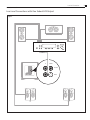
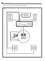
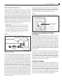
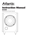
1
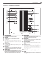
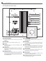
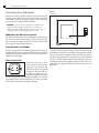
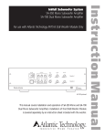
High Performance Powered Subwoofers
422 SB
212 SB
102 SB
Instruction Manual
Model 102 SB
Model 212 SB
Model 422 SB
2
Safety Precautions
Model 102, 212 and 422 SB Powered Subwoofer
Safety Precautions
CAUTION: To reduce the risk of electric shock, do not remove the
cover (or back). No user serviceable parts inside. Refer to qualified personnel.
WARNING: To reduce the risk of fire or electric shock, do not expose
this appliance to rain or moisture. This device generates a fair amount of
heat. Make sure nothing blocks the ventilation openings on the top and
bottom of the unit.
The lightning flash with arrowhead, within an equilateral
triangle, is intended to alert the user to the presence of
uninsulated “dangerous voltage” within the product’s
enclosure that may be of sufficient magnitude to constitute a risk of electrical shock to persons.
The exclamation point within an equilateral triangle is
intended to alert the user to the presence of important
operating maintenance (servicing) instructions in the
literature accompanying the appliance.
Table of Contents
2
3
4
5
6
Model 102, 212 and 422 SB
102 and 212 SB Subwoofer Rear Panel
422 SB Subwoofer Rear Panel
Features
Connecting Your Subwoofer
6
6
6
Subwoofer Line Out to Low Level In
Using the Low Level Output
Power Connection
7
8
9
9
Low Level Connections with One Subout/LFE Output
Low Level Connections with Two Subout/LFE Outputs
Placement and Operation
System Setup
9
9
10
10
10
10
Subwoofer Tuning Without an SPL Meter or Test Tones
How Much is Enough?
Dual Subwoofer Placement
Using the Subwoofer Crossover Control
The Phase Invert Control
A Word About Bass, Center Channel Modes
and System Set Up
10 Care of Your Subwoofer
11 Subwoofer Troubleshooting Guide
11 Specifications
For Future Reference
Record your serial numbers and date of purchase here:
Model Number
Serial Number
Date of Purchase
The serial number is found on the back panel.
Model 102, 212 and 422 SB
High Performance Powered Subwoofers
Congratulations on your purchase of an Atlantic Technology powered
subwoofer. A well designed subwoofer, properly integrated into your system, will enhance your listening pleasure dramatically by providing the
bass foundation upon which most music and special effects are built.
These subwoofers are capable of delivering very high output levels and
wide dynamic range. When properly placed, these subs will provide
smooth in-room bass response down to approximately 25Hz, with a peak
SPL of over 102dB in a normal sized room.
Their high-current amplifiers, coupled with their rugged long-throw
woofers in sealed enclosures, generates accurate deep bass with a minimum of distortion.
Copyright © 2004 Atlantic Technology International.
Specifications are those in effect at the time of printing. Atlantic Technology reserves the
right to change specifications or designs at any time without notice. THX and THX Ultra 2
are registered trademarks of Lucasfilm, Ltd. Dolby Digital, AC-3, Dolby Stereo and Dolby
Pro Logic are trademarks of Dolby Laboratories Licensing Corporation.
Your Atlantic Technology powered subwoofer will smoothly integrate
with virtually all brands of loudspeakers on the market. From the rocksolid amplifier to the easily accessible controls, this is one of the most
versatile high performance subwoofers you can buy.
Subwoofer Rear Panel
3
Instruction Manual
102 and 212 SB Subwoofer Rear Panel
Figure 1
1
BASS LEVEL
MIN
2
3
4
MAX
STATUS
ON
STANDBY
60 Hz
CROSSOVER
FREQUENCY
40 Hz
140 Hz
5
PHASE
NORMAL
INVERT
6
CROSSOVER
NORMAL
BYPASS
WARNING: TO REDUCE THE RISK OF FIRE OR ELECTRIC SHOCK
DO NOT EXPOSE THIS APPLIANCE TO RAIN OR MOISTURE.
RIGHT
7
9
AUTO
AVIS: RISQUE DE CHOC ELECTRIQUE-NE PAS OUVRIR
DOUBLE INSULATION - WHEN SERVICING USE ONLY IDENTICAL REPLACEMENT PARTS
L / MONO
OUTPUT
2001310
8
�����������
�����������
INPUT
������������
������������������
10
AC
INPUT
ON
11
12
CAUTION: FOR CONTINUED PROTECTION AGAINST
FIRE, REPLACE ONLY WITH SAME TYPE 250V FUSE
1
Variable Level Control
7
Status LED
This will be green for "on" condition, amber for "standby"
3
4
Crossover Control
An adjustable (40Hz to 140Hz) @ 18dB per octave low-pass crossover. (pages 5 and 9)
5
Crossover Switch
When in the NORMAL position, adjustment of the crossover can
be made by the Crossover Control. If being fed a pre-filtered or THX
signal, place the switch at the BYPASS position. (pages 5 and 9)
Low Level Input
Use the input to connect to the subwoofer or LFE line out from
your processor/receiver. (pages 5 and 6)
9
Product Serial Number
Write this number in the space provided on page 2 for future
reference.
10
Voltage Select Switch
Voltage switch for use in different countries. This switch will be set
when you receive the unit. Change this setting only when you are
sure your application requires it. For US, the switch should be set
to the 110-120V position.
Phase Switch
This switch allows precise acoustic matching with satellite speaker
systems whose output may be phase reversed. (pages 5 and 10)
6
8
Standby Switch
When in ON position, the amplifier will always be on. When in the
AUTO position, the amplifier will be in Automatic Standby Mode.
(pages 5 and 9)
Low Level Output
The outputs allow daisy chaining of multiple subwoofers, or as a
return path back to the processor. (pages 5 and 6)
Use this control to set the level of bass desired
2
FOR 115V, USE T2AL 250V FUSE
FOR 230V, USE T1.25AL 250V FUSE
11
On/Off Switch
Use this switch to turn the amplifier completely on or off.
12
AC Input
Use the included power cord to connect your amplifier to a wall
outlet. (pages 5 and 6)
4
Subwoofer Rear Panel
Model 102, 212 and 422 SB Powered Subwoofer
422 SB Subwoofer Rear Panel
Figure 1
ON
AUTO
STANDBY
5
60 Hz
Model 422 SB
CROSSOVER
FREQUENCY
1
40 Hz
140 Hz
6
NORMAL
INVERT
PHASE
7
NORMAL
BYPASS
CROSSOVER
8
OUTPUT
9
WARNING: TO REDUCE THE RISK OF FIRE OR ELECTRIC SHOCK
DO NOT EXPOSE THIS APPLIANCE TO RAIN OR MOISTURE.
RIGHT
L / MONO
AVIS: RISQUE DE CHOC ELECTRIQUE-NE PAS OUVRIR
DOUBLE INSULATION - WHEN SERVICING USE ONLY IDENTICAL REPLACEMENT PARTS
2001310
INPUT
10
AC
INPUT
11
2
3
4
1
AC INPUT 50 / 60Hz 500W MAX
FOR 115V, USE T5AL 250V FUSE
FOR 230V, USE T3.15AL 250V FUSE
CAUTION:
FOR CONTINUED PROTECTION AGAINST FIRE,
REPLACE ONLY WITH SAME TYPE 250V FUSE
Product Serial Number
6
2
On/Off Switch
7
AC Input
Use the included power cord to connect your amplifier to a wall
outlet. (pages 5 and 6)
4
5
8
9
Low Level Output
The outputs allow daisy chaining of multiple subwoofers, or as a
return path back to the processor. (pages 5 and 6)
Voltage Select Switch
Voltage switch for use in different countries. This switch will be set
when you receive the unit. Change this setting only when you are
sure your application requires it. For US, the switch should be set
to the 110-120V position.
Crossover Switch
When in the NORMAL position, adjustment of the crossover can
be made by the LowPass Control. If being fed a pre-filtered or THX
signal, place the switch at the BYPASS position. (pages 5 and 9)
Standby Switch
When in ON position, the amplifier will always be on. When in the
AUTO position, the amplifier will be in Automatic Standby Mode.
(pages 5 and 9)
Phase Switch
This switch allows precise acoustic matching with satellite speaker
systems whose output may be phase reversed. (pages 5 and 10)
Use this switch to turn the amplifier completely on or off.
3
Crossover Control
An adjustable (40Hz to 140Hz) @ 18dB per octave low-pass crossover. (pages 5 and 9)
Write this number in the space provided on page 2 for future
reference.
10
Low Level Input
Use the input to connect to the subwoofer or LFE line out from
your processor/receiver. (pages 5 and 6)
11
Front Mounted Variable Level Control and Status LED
Shown in greater detail on page 9
Features
5
Instruction Manual
Features
Your Atlantic Technology powered subwoofer has been engineered using
the latest technology and finest components available. It features:
■
A long-throw composite cone driver with a vented motor structure and 2” high temperature, 4-layer voice coil
■
The outputs allow daisy chaining of multiple subwoofers, or as a
return path back to the processor.
■
This powerful driver has a very stiff cone that acts like a piston
throughout its operating range. Its massive magnetic motor assembly and high temperature component parts deliver exceptional performance and reliability.
■
Sealed enclosure design for low distortion and deep bass output
High-current amplifiers
The output stage of these amplifiers are capable of very high current delivery for exceptional driver control and cool operation. They
have been precision matched and equalized to our rugged drivers.
Together they deliver powerful, controlled bass with great articulation and authority.
■
■
■
■
An adjustable (40Hz to 140Hz) @ 18dB per octave LowPass crossover
The steep upper end roll-off slope of 18dB per octave allows for much
better bass integration with the satellite speakers while making the
woofer less localizable.
NOTE: If you are using a surround Processor/Receiver that includes
its own filtered subwoofer output (or a THX Certified Processor/
Receiver), we strongly recommend that you set the crossover control to the Bypass position.
A convenient front panel mounted Level Control (422 SB)
Automatic standby operation, LED indicator
Automatic standby features signal sensing turn-on with 7-10 minute
turn-off delay. There’s a multi-color LED status indicator that lets you
know when the unit is on or in standby. Automatic Standby can be
defeated by placing the rear mounted switch in the ON position.
A useful in room working frequency range of 25Hz to 150Hz
Many subwoofers offer specifications that look great on paper, but in
real world use deliver less than promised. Atlantic Technology subwoofers are over-designed to ensure that they will deliver their rated
performance in your room, when properly placed and adjusted.
A Phase Invert switch (Normal/Invert)
This switch allows precise acoustic matching with satellite speaker
systems whose output may be phase reversed. This switch also allows
you to compensate for unusual room acoustics that occur when the
woofer is physically separated from the main speakers. Be sure to try
the Phase switch in both positions when you set up your subwoofer.
Even if you’ve simply changed the built-in crossover settings it’s a good
idea to try the Phase switch in both positions, since the crossover
control and the Phase switch acoustically interact with each other.
Pay particular attention to the transition of bass from the woofer to
the satellites, listening for smooth and well defined bass throughout
the range.
Sealed enclosure woofer designs are inherently low in distortion, and
deliver deep smooth bass response with a gradual and predictable
roll-off below resonance. As with all Atlantic Technology subwoofers,
we have paid close attention to providing accurate musical bass reproduction along with terrific special effects.
■
Two low level inputs, two low level outputs
■
An AC cord power input socket
Your subwoofer comes supplied with a heavy-duty detachable power
cord.
■
Designed and built to meet all current UL/CSA and European
safety requirements
R
6
Connecting
Your Subwoofer
L/MONO
Model 102, 212 and 422 SB Powered Subwoofer
Connecting Your Subwoofer
Use the low-level (RCA jack) subwoofer line out of your surround sound
receiver/processor. Simply connect your subwoofer with a high quality
shielded cable as shown in the diagram on page 7. Please consult your
processor/receiver manual for further information.
Figure 2
AC Connection
WARNING: To prevent risk of electrical shock or damage to your
equipment, always unplug all component AC cords before proceeding with speaker and component connections! The last step in
wiring your system should be plugging in the AC cords!
Subwoofer Line Out to Low Level In
Run an RCA cable from your receiver’s Sub Out jack to the L/Mono input
jack on the back of the subwoofer (Figure 3). If your receiver/processor
has stereo subwoofer
outputs, connect these to both the L/Mono and R
AC INPUT
50-60Hz 300W MAX
jacks on the
back of the subwoofer (Figure 4).
Using the Low Level Output
110-120V
220-240V
If desired,
you can run
a low level signal through the subwoofer and out
to another unit. This way you can add an additional subwoofer with minimal additional wiring. The signal that comes out of the output jacks is
identical
to the input signal.
ON
OFF
Power Connection
Connect the power cord to an AC
outlet only after making all other
connections to the subwoofer. This
will avoid any chance of accidentally
activating the subwoofer while wiring. Atlantic Technology does not
FOR 110-120VAC, USE 3A L 250V FUSE
recommend plugging the subwoofer
FOR 220-240VAC, USE 2A T 250V FUSE
into the switched outlet of an amplifier, preamplifier, or receiver. The
power demands of the subwoofer amplifier may exceed the power rating
of the switched outlet and may damage the equipment.
Your subwoofer is totally automatic in its operation. The automatic on/
off circuitry will only activate the subwoofer in the presence of an audio
signal from your system. After 7-10 minutes with no signal detected from
the rest of the system, the amplifier will shut itself off and go back into
standby mode. When the sub is in operating mode, the status LED will
glow green. The LED will glow amber in the Standby mode and power
consumption in this mode is negligible. Standby operation can be completely bypassed by placing the standby switch on the rear panel to the
ON position.
Low Level Connections
Instruction Manual
Low Level Connections with One Subout/LFE Output
Figure 3
Sub Out/LFE
R
L/MONO
OUTPUT
INPUT
7
8
Low Level Connections
Model 102, 212 and 422 SB Powered Subwoofer
Low Level Connections with Two Subout/LFE Outputs
Figure 4
Sub Out/LFE
Sub Out/LFE
R
L/MONO
OUTPUT
INPUT
Placement and Operation
9
Instruction Manual
Placement and Operation
Generally speaking, the best location for your new subwoofer is the front
of the room, close to a corner (Figure 5). Every room has its own unique
sound characteristics, and flexibility in the exact placement of the subwoofer is always desirable. The closer the subwoofer is placed to a wall
and especially a corner, the more and deeper the bass response you will
hear. Because of an acoustic phenomenon known as "room gain," a welldesigned wubwoofer playing in an acoustically-favorable room may well
deliver low bass deeper than its rated response. However, in some rooms,
corner placement can produce a “one note” boomy effect. Under such
circumstances the subwoofer may work better away from the corner.
Experiment to find the best position in your room.
HELPFUL HINT: A particularly useful experiment is to place the
subwoofer right at the prime listening position (move your couch
or chair out of the way and put the sub in its place). Then play
something with good bass content (preferably music), and walk
around the room, listening to the subwoofer’s response. When
you locate an area that has an ample amount of well defined bass,
you’ve found a good potential place to locate the sub.
Figure 5
Typical arrangement for a single subwoofer in a home theater.
1. Start here
2. Move to
corner for
more bass
3. Move away
from wall for
less bass
System Set Up
When setting up a complete home theater we strongly recommend that
you use a Sound Pressure Level meter. Radio Shack® has a good one
that is very affordably priced (approximately $40-50). To use this meter,
turn on your system, put the Processor/Receiver in the Test Mode and
set its main volume control to 0dB. Sit in the prime listening position, set
the SPL meter to the 70dB scale, Slow Response, and C Weighting. Now,
holding the meter pointed up and in front of you, let the system cycle its
test tone from speaker to speaker and set every speaker to 75dB using
the individual level settings in the Processor/Receiver. As tempting as it
may be to set the subwoofer and/or surround speakers higher than 75dB,
listen again after calibration and see if you can acclimate to these levels.
Try watching several different movies and keep in mind that the goal is to
have a system that sounds like you’re actually “in the movie.”When using
the latest discrete digital electronics which include internal level controls
for all channels, we recommend setting the 422 SB's front mounted Level
Control to its Preset position and using the Processor/Receiver’s built-in
subwoofer level control.
On the 212 SB you can use the level control on the rear panel to make
this adjustment. If you decide not to use an SPL meter try to set all the
speaker levels the same using the Test Tones. Of course, this will be much
more difficult without the meter, especially for the subwoofer.
Figure 6
(422 SB only) Front Panel Variable Level Control located behind the removable grille
Recess and indicator for
level adjustment
Fixed Position
Indicator LED
Subwoofer Tuning Without an SPL Meter
or Test Tones
Start your listening with the subwoofer Crossover control set at around
100Hz or in the Bypass position if you’re using a THX Certified processor or unit with a built-in crossover. Set the phase switch to normal, and
the front panel variable level control (Figure 6) to the Preset position.
Play some music that you know has good bass content, and turn the
level control up until you just start to hear the subwoofer working. Now,
from your normal listening position, determine whether the subwoofer
is playing loudly enough and filling in the bass frequencies of the music
evenly. If adjustment is necessary, start by changing the setting in the
processor or with the level control if your processor lacks a subwoofer
level adjustment.
If the bass seems too ponderous, boomy, or heavy, no matter how you
set the level, try moving the subwoofer away from the wall/corner. If
the bass seems too thin, try moving the subwoofer closer to the wall/
corner. Small differences in positioning can make big differences in bass
response. When you find a position that seems to work well, try switching the phase switch between its two settings, listening particularly to the
transition from the subwoofer to the satellites.
How Much is Enough?
Sometimes people prefer more bass impact for movies. Using the movie
setting for music can result in overpowering and unnatural bass reproduction. You may wish to determine both a video level and an audio
level if you find yourself falling into this camp. Remember however, the
most common error people make when setting up their system is to play
the subwoofer (and surrounds) too loudly. Of course, the Home Theater
Police will not arrest you for this act. But should you desire the most
accurate overall reproduction, a well balanced sound from bass to highest treble is the best way to get it. Have fun. Experiment. Enjoy.
ON
AUTO
STANDBY
60 Hz
10
Care of Your Subwoofer
Model 102,CROSSOVER
212 and 422 SB Powered Subwoofer
FREQUENCY
CTRIC SHOCK
MOISTURE.
Dual Subwoofer Placement
The Phase Invert Control
When two subwoofers are used, you may wish to place them asymmetrically; that is, in slightly different positions in the room (Figure 7). This
will reduce common mode room resonances that occur with symmetrically positioned subwoofers. You can also try placing the subwoofers in
the same corner, if you wish. Experiments have shown this to be a viable
means of producing smooth bass response in many rooms.
A subwoofer operating out of phase
with
the rest of the system won’t proPHASE
vide optimum low frequency performance. Also, the correct subwoofer
phase
can
enhance
room
acoustics.
Since there is so much variation in
NORMAL
BYPASS
CROSSOVER
the industry regarding phase, a switch that will reverse the phase of the
subwoofer is provided on the amplifier panel. Listen to a monaural musicalRIGHT
source with
strong bass content. (For example, you can use the mono
L / MONO
switch on an FM tuner or preamp, or use a Y-connector on the outputs
of one of your source components toOUTPUT
get a mono signal.)
Figure 7
Asymmetrical arrangement for 2 subwoofers in a home theater, for example, one
closer to a corner than the other
S OUVRIR
AL REPLACEMENT PARTS
Place subwoofers
assymmetrically in room
for smoother bass
2001310
40 Hz
NORMAL
140 Hz
INVERT
Experiment with the position of the phase switch to get the smoothest
bass. It should be obvious which is the correct setting. In particular, there
will be a more integrated transition between the satellites and the subwoofer when they are properly phased.
INPUT
A Word About Bass, Center Channel Modes
and System Set Up
ONthe Subwoofer
AUTO
STANDBY
Using
Crossover
Control
When used with the System 1200 or 2200,
the Crossover control should be set at
around
100Hz unless you are using a proCROSSOVER
cessor
with its own built-in crossover. The
FREQUENCY
goal is to optimize the performance of the
40 Hz
140 Hz
system by ensuring that the subwoofer and
satellites produce a cohesive and well integrated sound “picture.”
60 Hz
NORMAL
INVERT
PHASE
Many surround sound receivers and processors offer a choice of crossovers, typically between 80 Hz and 120 Hz. If yours does, we recommend
using
the 100Hz setting
when using
small speakers such as those in the
NORMAL
BYPASS
CROSSOVER
00W MAX
System 1200 or 2200.CAUTION:
Consult your electronics owner's manual for more
FOR CONTINUED PROTECTION AGAINST FIRE,
50V FUSE
details.
REPLACE ONLY WITH SAME TYPE 250V FUSE
L 250V FUSE
RIGHT
L / MONO
Higher crossover frequencies pass more bass but can sound boomy
and may be more easily localized to the subwoofer. Higher crossover
OUTPUT
frequencies may be suitable, however,
when using very small satellites
that have no real low frequency performance. Settings lower than 80Hz
should be employed if you are using larger speakers that have extended
bass response. This way, the subwoofer will only reproduce the very lowINPUT
est bass frequencies that are in the range where the large main speakers
begin to roll off.
It’s generally undesirable to have the main speakers and the subwoofer
overlap too much. Larger speakers means a lower Low-pass crossover
frequency, smaller speakers means a higher Low-pass crossover frequency. Consult the manufacturer’s specified low frequency response
for your main speakers to determine the appropriate Low-pass setting
on your subwoofer. In the end, however, a little time spent experimenting
will generally result in dramatically better bass response.
Many surround processors and receivers feature a “Wide” and “Normal”
mode for the center channel speaker. Atlantic Technology recommends
that the center channel be operated in the “Normal” mode when using
a powered subwoofer. The center channel speaker will sound more
dynamic and the intelligibility of the system will generally be improved
when in the “Normal” mode.
With discrete digital 5.1, 6.1, or 7.1 channel systems (Dolby Digital, DTS,
etc.) many controllers provide a Bass Management option, which lets you
set the front and rear speakers in a limited bandwidth (Small) or full
range (Large) mode. When using a subwoofer with Atlantic Technology
speakers we recommend setting such a controller to the Small position
for all the speakers in the system.
Care of Your Subwoofer
The 102 SB, 212 SB and 422 SB are constructed from Medium Density
Fiberboard. MDF is a non-resonant material ideal for speaker system
enclosures. To clean the cabinet you may use a soft cloth either dry or
slightly dampened with clean water. Be careful not to wet the cabinet or
allow any water to enter the cabinet seams. Avoid placing your speakers
in direct sunlight or near a source of heat that may, over time, damage
the finish.
IMPORTANT: Save Your Boxes! If you can do so, save the carton,
packing pieces and plastic bags that came with your subwoofer.
They will be useful in case you move or have to ship your subwoofer for any reason. In any case, save all packing materials until
you are certain that the system has suffered no damage in shipment. If you find such damage, either visible or internal, contact
your dealer immediately for the proper return procedure.
Subwoofer Troubleshooting Guide
11
Instruction Manual
Subwoofer Troubleshooting Guide
Once your subwoofer is set up, you should have many years of maintenance free enjoyment from your system. However, if you should encounter a
problem, refer to the following guide to help you find the solution. If a problem persists, you should contact your local authorized Atlantic Technology dealer.
Problem
Possible Cause
Possible Solution
No bass output
AC power cord unplugged or
plugged into a non-working outlet.
Plug into a working outlet.
Input cables not securely
connected or defective.
Check all connections, then try another
input cable.
Input cable not securely connected
or defective.
Check all connections, then try another
input cable.
Ground loop through antenna or
cable TV system input.
Test by disconnecting antenna and/or cable
system input leads. If hum goes away, install
isolation balun(s) at that point.
Audible buzz or hum
Specifications
Model 102 SB
Model 212 SB
Model 422 SB
Type/Features
Powered subwoofer, sealed enclosure
Powered subwoofer, sealed enclosure
Powered subwoofer, sealed enclosure
Bass Driver
8” long-throw composite cone
10” long-throw composite cone
12” long-throw composite cone
Output Power
100W RMS
125W RMS
225W RMS
Distortion (amplifier)
<0.5%
<0.5%
<0.5%
Frequency Response
34Hz – 250Hz ±3 dB
30Hz – 250Hz ±3 dB
25Hz – 250Hz ±3 dB
Low Level (line)
20k
20k
20k
Peak Output
102dB SPL into 1500 cubic Feet
102dB SPL into 2000 cubic Feet
103dB SPL into 2000 cubic Feet
Dimensions (WxHxD)
including side panels
13.2 x 13 x 12.2 in
335 x 330 x 310mm
15.25 x 15 x 16.9 in
388 x 380 x 430mm
17.25 x 17.75 x 16.9in
438 x 450 x 430mm
Weight
31lbs/14.1kg
37.5lbs/17kg
44lbs/20kg
Power Requirements
110-120/220-240V,
50/60Hz, 300W Max
110-120/220-240V,
50/60Hz, 300W Max
110-120/220-240V,
50/60Hz, 500W Max
Specifications are those in effect at the time of printing. Atlantic Technology reserves the right to change specifications or designs at any time without notice. THX is a registered trademark of Lucasfilm Ltd. Dolby Digital, Dolby Stereo, and Dolby Pro Logic are trademarks of Dolby Laboratories
Licensing Corporation. DTS is a registered trademark of Digital Theater Systems, Inc.
343 Vanderbilt Avenue Norwood, MA 02062 (781) 762-6300 www.atlantictechnology.com
015-0442-A