1
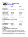
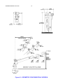
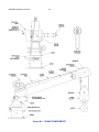
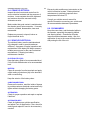
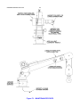
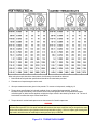
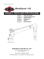
0000WS65:99900663: 20061106
WorkSaver™ 65
Volume 2 - PARTS AND SPECIFICATIONS
Section
Section
Section
Section
Section
Section
1
2
3
4
5
6
SPECIFICATIONS
CRANE DESCRIPTION
INSTALLATION
OPERATION
PARTS
MAINTENANCE
IOWA MOLD TOOLING CO., INC.
BOX 189, GARNER, IA 50438-0189
TEL: 641-923-3711
MANUAL PART NUMBER 99900663
Iowa Mold Tooling Co., Inc. is an Oshkosh Truck Corporation company.
0000WS65:99900663: --------
DATE
20010213
20011018
20030611
LOCATION
5-02
1-2, 5-9 through 5-11
6-1, 6-3
1-2
20060321
20061106
5-2
1-1, 5-1
REVISIONS LIST
DESCRIPTION OF CHANGE
ecn9000-41710972-1/2-13 HEX NUT WAS JAM NUT
Removed electrically operated worm gear option from manual. Not an option.
Removed 1-7 - Options (included pedestal mount, worm gear.) NOTE - option no longer available
after August 1995.
ECN 10001 - Changed mast assembly 41710972.
NEW OWNERSHIP STATEMENT; UPDATED SERIAL TAG LOCATION INFO.
0000WS65:99900663: 19971010
-READ FIRSTSAFETY PRECAUTIONS
Read and understand the IMT Operator’s Crane
Safety Manual before operation of the crane.
Raise load no higher than required to perform
the lift.
DO NOT exceed crane capacity.
Lubricate as required - regularly.
Before attempting full capacity lifts, practice with
light loads to familiarize yourself with crane
operation and controls. Also, observe tilt and
effects on the carrier vehicle’s body during
loading.
The vehicle’s emergency brake must be set
prior to crane operation.
Remove the remote control cable from the
crane when the crane is left unattended, even
for short time periods.
NEVER operate the crane near electrically
charged power lines or other sources of
electricity.
The remote control cable must be kept away
from the crane to avoid entanglement. Be
certain never to allow the cable to be crushed
by any outrigger or crimped between anything.
The path of the crane must be clear of all
personnel and obstructions.
DO NOT use winch when crane is in the stored
position.
Load ratings are based on crane capacity, not
unit stability.
DO NOT permit cable to be totally unwrapped
from drum. There should be no less than 3
wraps of cable on the drum during operation.
When winding cable onto the winch, apply
tension to the cable to keep it straight.
DO NOT weld, modify, or use unauthorized
parts. This can result in crane failure, causing
serious injury or death.
DO NOT wrap wire rope around the load. Use
chains or hooks designed for the job.
ALWAYS store the outriggers and crane
properly before moving the carrier vehicle.
Continuous use of the crane winch should be
avoided to prevent overheating of the electric
motor.
DO NOT permit unecessary objects to be in the
vicinity of the crane during operation.
Check the crane hook for cracks and distortion,
and safety latch for function, prior to work each
day.
The carrier vehicle must meet minimum chassis
specifications but these specifications do not
guarantee unit stability.
The safety latch of the hook must be closed
before lifting a load.
The crane must be installed per IMT
specifications. Consult your local distributor or
IMT for any required information.
A heavy-duty battery of 85 ampheres or more is
recommended.
Outriggers must be used to stabilize the vehicle
whenever the crane is in use.
The vehicle must be on a level surface for crane
operation.
Outriggers must be positioned correctly on a
firm surface.
Read and familiarize yourself with the
IMT OPERATOR’S CRANE SAFETY MANUAL
before operating or performing any
maintenance on your crane.
0000WS65:99900663: 20000801
NOTES
0000WS65:99900663: 19921030
TABLE OF CONTENTS
PARAGRAPH TITLE
PAGE
Section 1. SPECIFICATIONS
1-1.
GENERAL
1-2.
LIFTING CAPACITY
1-3.
PERFORMANCE CHARACTERISTICS
1-4.
POWER SOURCE
1-5.
WINCH
1-6.
CONTROLS
1-7.
OPTIONS
1-1
1-1
1-1
1-1
1-1
1-2
1-2
Section 2. CRANE DESCRIPTION
2-1.
GENERAL
2-2.
BASE
2-3.
MAST
2-4.
LOWER BOOM
2-5.
WINCH ASSEMBLY
2-6.
ELECTRICAL ASSEMBLY
2-7.
OUTRIGGERS
2-1
2-1
2-1
2-1
2-1
2-1
2-1
Section 3. INSTALLATION
3-1.
GENERAL
3-2.
INSTALLATION
3-1
3-1
Section 4. OPERATION
4-1.
GENERAL
4-2.
INSPECTION
4-3.
JOB SET-UP
4-4.
PERFORMING A LIFT
4-5.
STORING THE CRANE
4-1
4-1
4-1
4-1
4-2
Section 5. PARTS
5-1.
GENERAL
5-2.
CRANE IDENTIFICATION
5-3.
WELDMENT IDENTIFICATION
5-4.
ORDERING REPAIR PARTS
5-1
5-1
5-1
5-1
Section 6. MAINTENANCE
6-1.
GENERAL
6-2.
LUBRICATION
6-3.
WIRE ROPE REPLACEMENT
6-4.
CRANE ELECTRICAL
6-5.
VEHICLE ELECTRICAL
6-6.
CLEANLINESS
6-1
6-1
6-1
6-2
6-2
6-2
0000WS65:99900663: 20011018
FIGURE
A-1.
A-3.
A-4.
B-1.
C-1.
C-2.
D-1.
D-2.
D-3.
D-4.
E-1.
E-2.
E-3.
E-4.
E-5.
E-6.
E-7.
E-8.
E-9.
E-10.
E-11.
E-12.
F-1.
F-2.
TITLE
LIST OF ILLUSTRATIONS
CAPACITY CHART
GEOMETRIC CONFIGURATION - 5' VERSION
GEOMETRIC CONFIGURATION - 7' VERSION
CRANE COMPONENTS
MOUNTING DIMENSIONS
MOUNTING HARDWARE
HOOK SAFETY LATCH
BOOM POSITIONING DIAGRAM - 5' VERSION
BOOM POSITIONING DIAGRAM - 7' VERSION
STORED POSITION - TALL BASE MODELS
SERIAL NUMBER PLACARD
WELDMENT PART NUMBER LOCATIONS
BASE WELDMENTS
MAST ASSEMBLY - 5' & 7' VERSIONS
LOWER BOOM ASSEMBLY - 5' VERSION
LOWER BOOM ASSEMBLY - 7’VERSION
WINCH ASSEMBLY
HOOK BLOCK ASSEMBLY
ELECTRICAL ASSEMBLY - MANUAL SWING
DECAL KIT
OUTRIGGER ASSEMBLY - DROP LEG
OUTRIGGER ASSEMBLIES
MAINTENANCE POINTS
TORQUE DATA CHART
PART NUMBER
41710972
41711029
41711028
31711022
51711010
41711170
95711049
41711109
PAGE
1-2
1-3
1-4
2-2
3-1
3-1
4-2
4-3
4-3
4-4
5-1
5-1
5-2
5-2
5-3
5-4
5-5
5-5
5-6
5-7
5-8
5-8
6-3
6-4
0000WS65:99900663: 19921211
1-1
Section 1. SPECIFICATIONS
WorkSaver ™ 65
1-1. GENERAL SPECIFICATIONS
5' VERSION
6500 ft-lbs (0.899 ton-meters)
7' VERSION
6500 ft-lbs (0.899 ton meters)
MAXIMUM HORIZONTAL REACH
from centerline of rotation
5'-2'’ (1.57m)
7'-1'’ (2.16m)
MANUAL BOOM EXTENSION
boom +20°(.349 rad.) above horizontal
3'-3'’ to 5'-2'’ (.99 to 1.57m)
4'-3'’ to 7'-1'’ (1.30 to 2.16m)
LIFTING HEIGHT
from base of crane with tall base
8'-10'’ (2.69m)
11'-9'’ (3.58m)
CRANE WEIGHT (tall base)
220 lbs (99.8 kg)
260 lbs (117.9 kg)
CRANE WEIGHT (short base)
160 lbs (72.6 kg)
180 lbs (90.7 kg)
CRANE STORAGE HT. (tall base)
46'’ (1.17m)
59.5'’ (1.51m)
CRANE STORAGE HT. (short base)
31'’ (0.79m)
34'’ (0.86m)
MOUNTING SPACE REQUIRED
FOR BASE PLATE
10'’ x 10'’ (25.4 x 25.4cm)
10'’ x 10'’ (25.4 x 25.4cm)
MOUNTING BOLT PATTERN
CENTER TO CENTER
8'’ x 8'’ (20.3 x 20.3cm)
8'’ x 8'’ (20.3 x 20.3cm)
CRANE RATING
1-2. LIFTING CAPACITY
from centerline of rotation with boom +20° (.35 rad.) above horizontal.
3'-3'’ (.99m)
2000 lbs (907.2 kg)
4'-3'’ (1.30m)
1540 lbs (698.5 kg)
5'-2'’ (1.57m)
1260 lbs (571.5 kg)
6'-2'’ (1.89m)
—
7'-1'’ (2.16m)
—
—
1540 lbs (698.5 kg)
1260 lbs (571.5 kg)
1050 lbs (476.3 kg)
920 lbs (417.3 kg)
1-3. PERFORMANCE CHARACTERISTICS
ROTATION (manual with lock)
LOWER BOOM ELEVATION
(4 manually pinned locations)
EXTENSION BOOM
(manual pull-out)
346° (6.04 rad)
-90° (-1.57 rad) stowed
+20° (.35 rad)
+40° (.70 rad)
+60° (1.05 rad)
23'’ (58.4cm)
346° (6.04 rad)
-90° (-1.57 rad) stowed
+20° (.35 rad)
+40° (.70 rad)
+60° (1.05 rad)
34'’ (86.4cm)
1-4. POWER SOURCE
12VDC chassis must have minimum 50-amp alternator. Chassis battery must be deep cycle with a
minimum of 80 amp/hour rating and 450 cold cranking amp capacity.
1-5. WINCH
The winch is powered by 12VDC supplied by the chassis battery to a 12VDC motor through a planetary
gear drive. Maximum current draw under 2000 lbs (907 kg) double-line load is 95 amps. Minimum
effective double-line winch capacity is 2000 lbs (907 kg). Maximum effective single-line capacity is
1000 lbs (454 kg). Maximum single-line speed under no load is 16 feet/minute (4.88 meters/minute) at a
current draw of 20 amps and 5.5 feet/minute (1.67 meters/minute) under 2000 lbs (907 kg) load.
The winch is equipped with 25 feet (7.62m) of 3/16 inch (0.48cm) 7 x 19 class extra-flexible galvanized
“aircraft” cable with minimum breaking strength of 4200 lbs (190.5 kg). A snatch block with hook and
safety latch are included.
0000WS65:99900663: 20030611
1-2
1-6. CONTROLS
Remote control with a 10'-0" (3.05m) detachable control cable. The included battery cable is 25' (7.62m)
in length.
IMT reserves the right to change specifications and design without notice.
IOWA MOLD TOOLING CO., INC.
BOX 189, GARNER, IA 50438-0189
TEL: 641-923-3711
WorkSaver™ 65
641-923-3711
Figure A-1. CAPACITY CHART
0000WS65:99900663: 19921030
1-3
Figure A-3. GEOMETRIC CONFIGURATION-5’ VERSION
0000WS65:99900663: 19921030
1-4
Figure A-4. GEOMETRIC CONFIGURATION-7’ VERSION
0000WS65:99900663: 19921030
2-1
Section 2. CRANE DESCRIPTION
2-1. GENERAL
2-4. LOWER BOOM
This section describes the assemblies that
make up the IMT WorkSaver™ 65. Figure B-1
illustrates the locations of the assemblies, as
well as various other components of the crane.
The standard lower boom assembly provides
for a horizontal reach from centerline of rotation
of 3'-3" to 5'-2" (.99 to 1.57m) The optional
lower boom assembly provides for a reach of 4'3" to 7'-1" (1.30 to 2.16m). This is accomplished
through the use of a manually operated
extension boom stored within the lower boom.
The lower boom also provides mounting
brackets for the winch and control box, and
necessary locking pins. The extension boom
includes mounting location for the sheave.
2-2. BASE
The base provides the means for mounting the
crane to the carrier vehicle. There are three
versions which vary in height. The standard
base provides for a folded sorage position and
is 39.62'’ (1.01m) high on the 5' version and
53.12'’ (1.35m) on the 7' version. A short
pedestal base is optional and available for both
5' and 7' versions and is 6.25'’ (15.9cm) high.
2-3. MAST
The standard mast, for both the 5' and 7'
versions, incorporates a manually operated
swing and locking mechanism with rotation
capabilities of 346° (6.04 rad.). An optional
electrically operated worm gear rotation
mechanism is available. It is controlled by a
switch on the remote control handle and also
provides 346° (6.04 rad.) rotation.
2-5. WINCH ASSEMBLY
The winch assembly includes the electric
winch, sheave, hook block and mounting
hardware. The winch is powered by the carrier
vehicle’s 12VDC electrical system.
2-6. ELECTRICAL ASSEMBLY
The electrical assembly includes the necessary
12VDC controls and wiring for operation of the
winch.
2-7. OUTRIGGERS
Various manually operated outrigger assemblies
are available, dependent on chassis selection.
These assemblies are illustrated in the parts
section.
0000WS65:99900663: 19930503
2-2
Figure B-1. CRANE COMPONENTS
0000WS65:99900663: 19930211
3-1
Section 3. INSTALLATION
3-1. GENERAL
This section provides installation instructions for
the IMT WorkSaver™ Crane. See Figure E-9
for specific winch remote control wiring for
cranes with manual swing and Figure E-14 for
those with power swing.
Locate the base with the rotation stop positioned
for your particular application which is normally
away from the most used working position.
Secure the base to the mounting surface using
four (4) 5/8-11, hex head, grade 5, cap screws;
eight (8) 5/8" flat washers and four (4) 5/8-11
self-locking, hex nuts. See Figure C-2.
3-2. INSTALLATION
The mounting space required for the crane base
is 10" x 10" (25.4 x 25.4cm) with a square bolt
hole pattern measuring 8" x 8" (20.3 x 20.3cm).
Before determining the location for mounting,
keep in mind that the 5' version crane has a
horizontal reach from centerline of rotation of
62" (1.57m) and the 7' version has a reach of
85" (2.16m). Also important is that the crane
has a 346° (6.04 rad) rotation capability.
Using the holes in the base as a pattern, mark
the location of the four mounting holes as well
as the inside electrical access hole. Drill 11/16"
diameter holes at these five (5) locations. See
Figure C-1.
CAUTION
BEFORE DRILLING MOUNTING HOLES, CHECK
BELOW THE MOUNTING SURFACE FOR ANY
OBSTRUCTIONS, FUEL LINES, EXHAUST OR
ELECTRICAL COMPONENTS.
Figure C-1. MOUNTING DIMENSIONS
After securing the base in position, feed the two
wires from the end of the mast through the
electrical access hole. Place the mast
assembly into the base, being careful not to
pinch the wires.
Once the crane is in place, run the positive feed
wire, with circuit breakers, along the truck
frame and connect to the starter side of the
starter solenoid. Secure this wire to the truck
frame using cable clamps at approximately 18"
(45cm) intervals. The negative lead wire must
be connected to a good ground on the truck
frame. Prepare the ground location by sanding
all paint or rust down to bare metal for maximum
ground contact. Secure this wire to the truck
frame using cable clamps at 18" (45cm)
intervals.
Figure C-2. MOUNTING HARDWARE
0000WS65:99900663: 19921030
3-2
NOTES
0000WS65:99900663: 19921030
4-1. GENERAL
4-1
Section 4. OPERATION
This section describes set-up, general operation
and storage procedures. It is the operator’s
responsibility to familiarize himself with these
procedures and conform to safety standards as
specified in the IMT Operator’s Crane Safety
Manual and any Federal, State or local codes.
4-2. INSPECTION
An inspection of the crane and vehicle should
be performed daily, before the crane is used.
Visually inspect the crane for:
•
•
•
•
•
•
•
•
•
STRUCTURAL DAMAGE
LOOSE PARTS
MOUNTING BOLT TIGHTNESS
HOOK DEFORMATION/CRACKS
WIRE ROPE DEFORMATIONS
ELECTRICAL SYSTEM MOISTURE
PROPER ELECTRICAL CONTACTS
PROPER LUBRICATION
SHEAVES & DRUM FOR CRACKS/WEAR
Visually inspect the vehicle for:
•
•
•
•
•
UNDER-INFLATED TIRES
WORN/UNSAFE TIRES
BROKEN SPRINGS/SUSPENSION
FULLY CHARGED BATTERY
SECURE PARKING BRAKE
Any defects found or suspected should be
reported and corrected immediately.
4-3. JOB SET-UP
Before operation, position the crane so the load
can be handled easily without obstructions and
within specified range of crane. The vehicle
must be parked on a firm, level surface.
WARNING
THE PRESENCE OF ANY ELECTRICALY
CHARGED POERLINES IS TO BE AVOIDED.
FAILURE TO DO SO WILL RESULT IN SERIOUS
INJURY OR DEATH. CONSULT THE IMT
OPERATOR’S CRANE SAFETY MANUAL FOR
FURTHER INFORMATION.
Engage the emergency brake, turn the ignition
OFF and place the transmission in PARK (on
automatic transmissions).
With the vehicle secured, extend the outriggers
so they are positioned on a firm surface and
locked into position.
Remove the control handle/cable from its
storage container and plug it into the receptacle
at the left side of the lower boom.
WARNING
DO NOT ALLOW PERSONNEL WITHING 10 FEET
OF ANY PORTION OF AN OPERATING CRANE.
Turn rotation locking handle on mast
counterclockwise to release tension on base.
Manually rotate crane to a position where the
boom can be manipulated and tighten locking
handle by turning clockwise. On the optional
power swing model, rotate the crane by using
the appropriate switch on the remote control
handle.
Position the boom at either of its positions above
horizontal. Physically lift the boom and insert
the quick release pin into position (20°, 40° or
60°) as shown in Figure D-2 or D-3.
To extend the boom, unwind a few feet of cable
from the winch and pull the extension boom out
to line-up the desired extension boom pin hole
with that in the lower boom. Insert the extension
boom pin.
WARNING
DO NOT PULL EXTENSION BOOM COMPLETELY
OUT OF LOWER BOOM AS IT CAN CAUSE
SERIOUS PERSONAL INJURY IF DROPPED.
The crane is now in the work position.
4-4. PERFORMING A LIFT
First, know the weight of the load being lifted
and that that load is within the capacity of the
crane.
WARNING
NEVER EXCEED THE CRANE’S RATED LOAD
CAPACITIES.
DOING SO WILL CAUSE
STRUCTURAL DAMAGE AND DAMAGE TO THE
WINCH AND CABLE WHICH CAN LEAD TO
SERIOUS INJURIES OR DEATH.
Position the hook block directly over the load by
rotating the crane. Lower the hook block by
pressing the control switch DOWN until the
hook can be attached to a sling or other suitable
handling device which is securely attached to
the load. The sling must be captivated by the
safety latch. See Figure D-1.
WARNING
DO NOT WRAP THE WINCH WIRE ROPE AROUND
THE LOAD. THIS WILL DAMAGE AND WEAKEN
THE WIRE ROPE, MAKING IT EXTREMELY
DANGEROUS.
0000WS65:99900663: 19921030
4-2
By pressing the control switch in the UP
position, lift the load slightly off the ground to
test the load and effect on the outriggers and
vehicle. If there are no indications of problems,
the load can be lifted to the desired height by
continuing to press UP. When the load is at the
desired height, swing the crane slowly over the
desired position.
To lower the load, press the switch DOWN,
making certain there are no obstructions under
the load. Release tension on the hook/sling and
remove the sling from the hook, being careful
not to let it swing out of control.
4-5. STORING THE CRANE
Before leaving the job site, it is necessary to
store the crane. Retract the extension boom by
removing the pin in the lower boom and
positioning the extension boom in its fully
retracted position. Insert the locking pin.
On short base models, the boom tip should be
lowered to the deck and secured in that position.
Tall masts provide a pin hole for storage of the
boom at a -90° position. Remove the boom
angle locking pin and gently lower the boom to a
verticle position. Insert the pin as shown in
Figure D-4.
Attach the hook to the hook hanger bracket as
shown in Figure D-3. Be certain the winch
cable is drawn up firmly and that all loose
objects are stored before driving the carrier
vehicle.
Disconnect the remote control handle cable and
store in the truck cab or other suitable, secure
location.
WARNING
NEVER DRIVE THE VEHICLE UNLESS THE CRANE
IS IN THE STORED POSITION AND SECURED
PROPERLY.
Figure D-1. HOOK SAFETY LATCH
0000WS65:99900663: 19921030
4-3
Figure D-2. BOOM POSITIONING DIAGRAM-5’ VERSION
Figure D-3. BOOM POSITIONING DIAGRAM-7’ VERSION
0000WS65:99900663: 19921030
4-4
Figure D-4. STORED POSITION-TALL BASE MODELS
0000WS65:99900663.01.20000706
5-1
Section 5. PARTS
5-1. GENERAL
5-3. WELDMENT IDENTIFICATION
This section contains the parts drawings and
accompanying parts lists for the assemblies
used on the crane. These drawings are
intended to be used for parts identification and
as an aid in ordering parts.
Each of the major weldments; base, mast, lower
boom and extension boom have a part number
stamped on the weldment. The location of the
part numbers are shown in Figure E-2.
5-2. CRANE IDENTIFICATION
Every IMT crane has an identification placard
(Figure E-1) attached to the crane in a
prominent location. When ordering parts,
communicating warranty information, or
referring to the unit in correspondence, always
include the serial number and model number.
Inquiries should be directed to:
Iowa Mold Tooling Co., Inc.
Box 189, Garner, Iowa 50438-0189
Telephone: 641-923-3711
Technical Support Fax: 641-923-2424
5-4. ORDERING REPAIR PARTS
When ordering replacement parts it is important
to follow the steps as outlined below.
1. Give the model number of the unit.
2. Give the serial number of the unit.
3. Specify the complete part number.
4. Give a complete description of the part.
5. Specify the quantity required.
IOWA MOLD TOOLING CO., INC.
BOX 189, GARNER, IA 50438-0189
SERIAL
NUMBER
MFG
DATE
70029119
MODEL
NUMBER
Figure E-1. SERIAL NUMBER PLACARD
Figure E-2. WELDMENT PART NUMBER LOCATIONS
0000WS65:41710972.01.REV. D 20060321
5-2
Figure E-3. BASE WELDMENTS
1.
2.
3.
4.
5.
6.
7.
8.
9.
10.
52710977
52710973
70055247
60116387
72062004
72060091
60116683
72063132
72066106
60125865
BASE WELDMENT
MAST WELDMENT
BEARING-BALL
SPACER-BEARING
NUT .50-13 HEX
CAP SCR .50-13X 1.00 HHGR5Z
BOLT-ANCHOR .50-13X 8.00
WASHER .50 FLAT ASTM F436
RETAINING RING-EXT 2.75 STD
BRAKE-LINING 1.5" x 1.5" x .188"
1
1
2
1
1
2
1
2
1
3
Figure E-4. MAST ASM-5' & 7' VERSION (41710972)
0000WS65:41711029.01.19921030
ITEM PART NUMBER
1.
2.
3.
4.
5.
7.
8.
52710978
52710971
70144211
70144209
70144234
72066143
72066679
DESCRIPTION
LOWER BOOM
EXTENSION BOOM
PIN 3/4X6-1/4 (INCL: 7)
PIN 3/4X4-1/4 (INCL:7)
PIN 3/4X6-1/4
HAIR PIN 1/8 (PART OF 3&4)
ROLL PIN 5/32X1-3/8
5-3
QTY
1
1
1
1
1
2REF
1
Figure E-5. LOWER BOOM ASM-5' VERSION (41711029)
0000WS65:41711028.01.19921030
ITEM PART NUMBER
1.
2.
3.
4.
5.
7.
8.
52710979
52710970
70144211
70144209
70144234
72066143
72066679
DESCRIPTION
LOWER BOOM
EXTENSION BOOM
PIN 3/4X6-1/4 (INCL: 7)
PIN 3/4X4-1/4 (INCL:7)
PIN 3/4X6-1/4
HAIR PIN 1/8 (PART OF 3&4)
ROLL PIN 5/32X1-3/8
5-4
QTY
1
1
1
1
1
2REF
1
Figure E-6. LOWER BOOM ASM-7' VERSION (41711028)
0000WS65: 31711022.01.19960603
ITEM PART NUMBER
1.
2.
3.
4.
5.
6.
7.
8.
9.
71570133
70056480
51711010
72060046
72060096
72062080
72063003
72661421
72066143
5-5
DESCRIPTION
QTY
WINCH-ELECTRIC
SHEAVE 5"PD
HOOK BLOCK ASSEMBLY
CAP SCR 3/8-16X1 HHGR5
CAP SCR 1/2-13X2-1/2 HHGR5
NUT 1/2-13 HEX LOCK
WASHER 3/8 WRT
CLEVIS PIN 1/2X2
HAIR PIN 1/8
1
1
1
3
1
1
3
1
1
NOTE:
1. THE WINCH IS SUPPLIED WITH 25 FT OF 3/16" DIA
GALVANIZED 7X19 AIRCRAFT CABLE WITH
SWAGED THIMBLE.
Figure E-7. WINCH ASM (31711022)
ITEM PART NUMBER
1.
2.
3.
4.
5.
6.
7.
60116446
71732760
70056480
72066143
72060928
72062080
72661421
DESCRIPTION
QTY
SIDE PLATE
HOOK 1.5TON SWIVEL
SHEAVE 5"
HAIR PIN 1/8
CAP SCR 1/2-13X2-1/4 HH GR5
NUT 1/2-13 HEX LOCK
CLEVIS PIN 1/2X2
2
1
1
2
1
1
2
NOTE:
1. TIGHTEN THIS CAP SCREW AND NUT TO
APPROXIMATELY .06" PLAY. THE SHEAVE
MUST BE FREE TO ROTATE.
Figure E-8. HOOK BLOCK ASM (51711010)
0000WS65:41711170.01.19940712
ITEM PART NUMBER
DESCRIPTION
1.
2.
3.
4.
5.
6.
7.
8.
9.
10.
11.
12.
13.
14.
REMOTE CONTROL HANDLE
CONTROL BOX ASSEMBLY
CABLE ASSEMBLY
CABLE ASSEMBLY
CABLE ASSEMBLY
PLASTIC TIE 14"
PLASTIC TIE 6-3/4"
CIRCUIT BREAKER 30AMP
CIRCUIT BREAKER 40AMP
CIR BRKR MTG BRKT
NUT 3/8-16 LOCK
CAP SCR 3/8-16X3/4 HH
NUT 1/4-20 LOCK
CAP SCR 1/4-20X1 HHGR5
77041461
77041460
51711025
51711024
51711023
70034069
70034060
77041357
77041320
70144821
72062103
72060044
72062104
72060004
5-6
QTY
1
1
2
1
1
1
1
1
1
2
1
1
2
2
Figure E-9. ELECTRICAL ASM-MNL SWING (41711170)
0000WS65:95711049.01.20000517
ITEM PART NO.
1.
2.
3.
4.
5.
6.
7.
8.
71393600
70393645
70392814
70029119
72066340
71394083
70394443
70395324
5-7
DESCRIPTION
QTY
CAPACITY PLACARD
DECAL-WORKSAVER
DECAL-DANGER OPERATOR
SERIAL NUMBER PLACARD
RIVET
DECAL-LOAD BLK RATING 2.0T
DECAL-DGR FREEFALL BOOM
DECAL-ASME/ANSI B30.5
1
2
1
1
2
2
1
1
NOTE:
SHIP DECALS 71393600 & 70392814 LOOSE FOR
SHORT BASE MODELS.
Figure E-10. DECAL KIT (95711049)
0000WS65:OUTRGERS.01.19970623
ITEM PART NUMBER
1.
2.
3.
4.
5.
6.
7.
8.
52711032
52711030
52711031
71731711
70392864
72060047
72062103
72063003
5-8
DESCRIPTION
QTY
OUTRIGGER PAD
DROP LEG OUTRIGGER
OUTRIGGER HOUSING
PIN 1/2X2-1/2 QUICK RELEASE
DECAL-DGR STAND CLEAR
CAP SCR 3/8-16X1-1/4 HHGR5
NUT 3/8-16 LOCK
WASHER 3/8 WRT
1
1
1
1
1
4
4
8
Figure E-11. OUTRIGGER ASM-DROP LEG (41711109)
16"
20"
24"
27"
OUTRIGGER
OUTRIGGER
OUTRIGGER
OUTRIGGER
ASSEMBLY
ASSEMBLY
ASSEMBLY
ASSEMBLY
(41711174)
(41711106)
(41711175)
(41711176)
16" 20" 24" 27”
ITEM PART NUMBER
1. 52711171
52711107
52711172
52711173
2. 52711108
3. 60116598
4. 60116602
5. 72060054
6. 72062103
7. 70392864
DESCRIPTION
OUTRIGGER WELDMENT 16"
OUTRIGGER WELDMENT 20"
OUTRIGGER WELDMENT 24"
OUTRIGGER WELDMENT 27"
HANDLE WELDMENT
OUTRIGGER TUBE
OUTRIGGER TUBE
CAP SCR 3/8-16X3 HH GR5
NUT 3/8-16 HEX LOCK
DECAL-DANGER STAND CLR
Figure E-12. OUTRIGGER ASMS
QTY QTY QTY QTY
1
1
1
1
1
1
2
2
1
1
1
1
2
2
1
1
1
1
2
2
1
1
1
1
1
2
2
1
0000WS65:99900663: 20011018
6-1
Section 6. MAINTENANCE
6-1. GENERAL
The WorkSaver™ 65 is easy to maintain but to
provide for maximum service life from this unit,
a program of periodic checks and maintenance
are necessary. This section describes
lubrication requirements and general
maintenance procedures. See Figure F-1 for a
graphic representation.
6-2. LUBRICATION
Lubrication is critical to the protection of your
crane. It provides for smooth operation and
protection from corrosion/rust. Following are the
areas which will require periodic lubrication.
ROTATION BEARINGS:
The two rotation bearings in the base were
lubricated at assembly. If the crane becomes
difficult to rotate or becomes noisy, inspect the
bearings and grease if necessary.
STANDARD ROTATION LOCKING HANDLE
THREADS:
Apply a light lubricant weekly to the threads to
provide for ease of operation and rust
prevention. Do not over lubricate or get oil on
the handle which could cause the operator to
loose his grip on the handle.
EXTENSION BOOM:
Lightly grease the sides of the extension boom
to provide for easy withdrawal from the lower
boom when adjusting crane reach. An
extension boom which is difficult to slide in and
out can be hazardous.
WIRE ROPE:
Wire rope is lubricated during its manufacture
but this lubrication will not protect the rope for its
service life. It is necessary to lubricate wire
rope in order to prevent corrosion, friction
created heat and to extend its life.
Lubricate the wire rope as follows:
1. Clean the rope of dirt, dust and any other
foreign matter.
2. Apply a light lubricant which will penetrate
the strands of the rope. Apply by dropping on,
spraying on or bushing on.
3. Apply lubricant heavily to portions which
encounter bending such as at the sheave and
winch.
6-3. WIRE ROPE REPLACEMENT
Replace the entire wire rope when any of the
following conditions exist:
1. When there are either 3 broken strands or a
total of six broken wires in all strands in any
rope lay.
2. When flat spots on the outer wires appear
and those outside wires are less than 2/3 the
thickness of the unworn outer wire.
3. When there is a decrease of diameter
indicating a core failure.
4. When kinking, crushing, birdcaging or other
distortion occurs.
5. When there is noticable heat damage
(discoloration) of the rope by any means.
6. When the diameter is reduced from nominal
size by 1/32" or more.
7. If a broken wire protrudes or loops out from
the core of the rope.
See the IMT Operator’s Crane Safety Manual
for more information concerning wire rope.
0000WS65:99900663: 19921030
6-4. CRANE ELECTRICAL
Inspect the winch motor and control box for
secure electrical contacts and the presence of
moisture. Loose contacts should be tightened
and moisture should be removed to help
eliminate corrosion.
Make certain that good contact is maintained at
the chassis ground wire connection. If severely
rusted or corroded, disassemble, clean and
reassemble.
Replace any severely crimped, broken or
frayed electrical wires.
6-5. VEHICLE ELECTRICAL
The vehicle’s battery must be maintained and
fully charged in order to provide maximum
efficiency. A program of regular inspection and
maintenance of the battery will help to assure a
reliable power source for the crane’s electrical
requirements. Following is a battery
maintenance checklist:
ELECTROLYTE LEVEL:
Keep the battery filled to its recommended level.
If low, fill with distilled water to its recommended
level.
BATTERY:
Clean all corrosion from the terminals and apply
a light coating of petroleum jelly to the terminals
when re-connecting.
Keep the exterior of the battery clean.
CABLE CONNECTIONS:
Remove all corrosion, sand the inside of clamps
to provide maximum electrical contact and firmly
tighten without damaging the battery posts.
ALTERNATOR:
Check for proper operation and repair or replace
if deficient.
ALTERNATOR BELT:
Check for tightness per vehicle specification
and adjust if out of specification. Also, check for
cracking and replace if found to be excessively
cracked.
6-2
Extremely cold conditions put extra strain on the
vehicle’s electrical system. Battery/electrical
maintenance is extremely important when
temperatures fall below 0°F.
Consult your vehicle owner’s manual for
specific information concerning your vehicle and
its recommended maintenance procedures.
6-6. CLEANLINESS
Keep the crane clean, and the decals legible to
the operator, especially the capacity placard
and warning decals. Cleanliness will make
inspection and maintenance easier. Also, the
application of wax to the crane will help protect
and prolong the life of the unit.
0000WS65:99900663: 20011018
6-3
Figure F-1. MAINTENANCE POINTS
0000WS65:99900663: 19921030
6-4
When using the torque data in the charts above, the following rules should be observed.
1. Bolt manufacturer’s particular specifications should be consulted when provided.
2. Flat washers of equal strength must be used.
3. All torque measurements are given in foot-pounds. To convert to inch-pounds, multiply by 12.
4. Torque values specified are for bolts with residual oils or no special lubricants applied. If special
lubricants of high stress ability, such as Never-Seez compound graphite and oil, molybdenum disulphite,
collodial copper or white lead are applied, multiply the torque values in the charts by the factor .90. The use of
Loctite does not affect the torque values listed above.
5. Torque values for socket-head capscrews are the same as for Grade 8 capscrews.
WARNING
Anytime a gear-bearing bolt is removed, it must be replaced with a new bolt of the identical grade and size. Once a
bolt has been torqued to 75% of its proof load and then removed, the torque coefficient may no longer be the same
as when the bolt was new thus giving indeterminate clamp loads after torquing. Failure to replace gear-bearing bolts
may result in bolt failure due to metal fatique causing serious injury or DEATH.
Figure F-2. TORQUE DATA CHART
0000WS65:99900663: 19960322
6-5
0000WS65:99900663: 20000706
6-6
LIMITED WARRANTY
WARRANTY COVERAGE - Products manufactured by Iowa
Mold Tooling Co., Inc. (IMT) are warranted to be free from
defects in material and workmanship, under proper use,
application and maintenance in accordance with IMT’s written
recommendations, instructions and specifications as follows:
WARRANTY VOIDED - All obligations of IMT under this warranty
shall be terminated:(1) if service other than normal maintenance
or normal replacement of service items is performed by
someone other than an authorized IMT dealer, (2) if product is
modified or altered in ways not approved by IMT.
1. Ninety (90) days; labor on IMT workmanship from the date of
shipment to the end user.
PURCHASER’S RESPONSIBILITY - This warranty covers only
defective material and workmanship. It does not cover
depreciation or damage caused by normal wear, accident,
improper protection in storage, or improper use. The purchaser
has the obligation of performing the care and maintenance duties
discussed in IMT’s written recommendations, instructions and
specifications. Any damage which results because of
purchaser’s failure to perform such duties shall not be covered
by this warranty. The cost of normal maintenance and normal
replacement of service items such as filters, belts, etc. shall be
paid by the purchaser.
2. One (1) year; original IMT parts from the date of shipment to
the end user.
IMT’s obligation under this warranty is limited to, and the sole
remedy for any such defect shall be the repair or replacement
(at IMT’s option) of unaltered parts returned to IMT, freight
prepaid, and proven to have such defect, provided such defect
occurs within the above stated warranty period and is reported
within fourteen (14) days of its occurence.
IMPLIED WARRANTY EXCLUDED - This is the only authorized
IMT warranty and is in lieu of all other express or implied
warranties or representations, including any implied warranties
of merchantability or fitness for any particular purpose or of any
other obligations on the part of IMT.
ITEMS EXCLUDED - The manufacturer gives no warranty on
any components purchased by the manufacturer, and such
components as are covered only by the warranties of their
respective manufacturers.
WARRANTY CLAIMS - Warranty claims must be submitted and
shall be processed in accordance with IMT’s established
warranty claim procedure.
WARRANTY SERVICE - Warranty service will be performed by
any IMT distributor authorized to sell new IMT products of the
type involved or by any IMT Service Center authorized to
service the type of product involved or by IMT in the event of
direct sales made by IMT. At the time of requesting warranty
service, the purchaser must present evidence of the date of
delivery of the product. The purchaser shall pay any premium
for overtime labor requested by the purchaser, any charge for
making service calls and for transporting the equipment to the
place where warranty work is performed.
CONSEQUENTIAL DAMAGES - The only remedies the
purchaser has in connection with the breach or performance of
any warranty on IMT products are those set forth above. In no
event will the dealer, IMT or any company affiliated with IMT, be
liable for business interruptions, loss of sales and/or profits,
rental or substitute equipment, costs of delay or for any other
special, indirect, incidental or consequential losses, costs or
damages.
REPRESENTATIONS EXCLUDED - IMT products are subject to
no expressed, implied or statutory warranty other than herein
set forth, and no agent, representative or distributor of the
manufacturer has any authority to alter the terms of this
warranty in any way whatsoever or to make any
representations or promises, express or implied, as to the
quality or performance of IMT products other than those set
forth above.
CHANGE IN DESIGN - IMT reserves the right to make changes
in design or improvements upon its products without imposing
any obligation upon itself to install the same upon its products
theretofore manufactured.
Effective January, 1985
This parts manual is provided to the user to assist in servicing the equipment. It is the propertyof Iowa Mold Tooling Co., Inc and, as such,
may not be reproduced either whole or in part,whether by chemical, electrostatic, mechanical or photographic means without the
expressedwritten permission of an officer of Iowa Mold Tooling Co., Inc. One manual is provided with each piece of new equipment and
additional manuals may be obtained at a nominal price.
IOWA MOLD TOOLING CO., INC.
BOX 189, GARNER, IA 50438-0189
TEL: 641-923-3711
TECHNICAL SUPPORT FAX: 641-923-2424