1
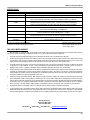
Universal Communication Module
For IPN™ Network compatible charge controllers
INSTALLATION AND OPERATION MANUAL
THIS MANUAL INCLUDES IMPORTANT SAFETY INSTRUCTIONS FOR MODEL:
UCM
SAVE THESE INSTRUCTIONS
© Blue Sky Energy, Inc. 2011
430-0030 B
Blue Sky Energy – Universal Communication Module
TABLE OF CONTENTS
IMPORTANT SAFETY INSTRUCTIONS ................................................................................................................................ 2
PRODUCT DESCRIPTION...................................................................................................................................................... 2
Part Numbers ......................................................................................................................................................... 2
UCM CONNECTION TO THE IPN NETWORK....................................................................................................................... 3
CONNECTING TO THE UCM’S WEB SITE ...........................................................................................................................
UCM Direct Computer Connection .........................................................................................................................
UCM Connection Using a Router ...........................................................................................................................
UCM Connection Over the Internet ........................................................................................................................
3
4
6
7
USING THE UCM’S WEB SITE .............................................................................................................................................. 7
Changing Settings and Executing Functions ......................................................................................................... 9
Using the IPN-ProRemote with a UCM .................................................................................................................. 9
TOP Web Page ...................................................................................................................................................... 9
ADVANCED DISPLAY Web Page ......................................................................................................................... 10
SETUP Web Page.................................................................................................................................................. 11
BATTERY CHARGE PARAMETERS Web Page................................................................................................... 12
UCM SETUP Web Page ........................................................................................................................................ 13
DATALOGGING ...................................................................................................................................................................... 13
Datalog Record Time Period .................................................................................................................................. 13
Datalog File Contents ............................................................................................................................................. 14
FTP .......................................................................................................................................................................................... 14
FTP Communication Settings ................................................................................................................................ 15
FTP File Contents .................................................................................................................................................. 15
MODBUS ................................................................................................................................................................................. 15
Electrostatic Handling Precautions ........................................................................................................................ 15
MODBUS Over TCP............................................................................................................................................... 15
Slave Address / Unit Identifier ................................................................................................................................ 16
Isolated RS-485...................................................................................................................................................... 16
RS-485 Serial Communication Settings ................................................................................................................. 15
Supported MODBUS Functions ............................................................................................................................. 16
Read Coils...................................................................................................................................... 16
Read Input Registers ..................................................................................................................... 17
Preset Single Register ................................................................................................................... 17
Force Coils ..................................................................................................................................... 18
UCM SETUP PARAMETERS.................................................................................................................................................. 19
As Shipped Factory Default Settings ..................................................................................................................... 19
Restoring As Shipped Factory Default Settings ..................................................................................................... 19
MOUNTING ............................................................................................................................................................................. 20
TROUBLESHOOTING GUIDE ................................................................................................................................................ 21
SPECIFICATIONS ................................................................................................................................................................... 22
TWO YEAR LIMITED WARRANTY ........................................................................................................................................ 22
TABLES AND FIGURES
Table 1
Table 2
Table 3
Table 4
Table 5
Table 6
Figure 1
Figure 2
Figure 3
Figure 4
Figure 5
1
Datalog File Data Descriptions ...................................................................................................... 14
FTP File Data Descriptions ............................................................................................................ 15
RS-485 Baud Rate and Parity Select............................................................................................. 16
Read Coils...................................................................................................................................... 16
MODBUS Registers .............................................................................................................. 17 & 18
Force Coils ..................................................................................................................................... 18
UCM Connections and Indicators .................................................................................................. 3
IPN Network & Power Cable Schematic ........................................................................................ 3
Crossover & Straight Thru Ethernet Cables .................................................................................. 4
UCM DIP Switch and Jumper Settings .......................................................................................... 16
Detailed Dimensional Drawing ....................................................................................................... 20
Installation and Operation Manual
IMPORTANT SAFETY INSTRUCTIONS
This manual contains important instructions for Model: UCM
SAVE THESE INSTRUCTIONS
1. Refer installation and servicing to qualified service personnel. Incorrect installation or use may result in risk of electric shock or fire. No user serviceable parts
in this unit.
2. To reduce the risk of electric shock, fire or personal injury, the following symbols are placed throughout this manual to indicate dangerous conditions, or
important safety or operational instructions.
WARNING
CAUTION
IMPORTANT
)
Indicates dangerous conditions or electric
shock potential. Use extreme caution.
Indicates items critical to safe installation or
operation of the unit.
Follow these instructions closely for proper
operation of the unit
3. PERSONAL PRECAUTIONS
a) Working in the vicinity of lead-acid batteries is dangerous. Batteries produce explosive gasses during normal operation.
b) To reduce risk of battery explosion, follow these instructions and those published by battery manufacturer and manufacturer of any equipment you intend
to use in vicinity of battery.
c) Someone should be within range of your voice or close enough to come to your aid when you work near a lead-acid battery.
d) Have plenty of fresh water and soap nearby in case battery acid contacts skin, clothing or eyes.
e) Wear complete eye protection and clothing protection. Avoid touching eyes while working near battery.
f) If battery acid contacts skin or clothing, wash immediately with soap and water. If acid enters eye, immediately flood eye with running cold water for at
least 10 minutes and get medical attention immediately.
g) NEVER SMOKE or allow a spark or flame in vicinity of battery.
h) Be extra cautious to reduce risk of dropping metal tool onto battery. It might spark or short circuit battery or other electrical part that may cause
explosion.
i) Remove personal metal items such as rings, bracelets and watches when working with a lead-acid battery. A lead-acid battery can produce a short
circuit current high enough to weld a ring or the like to metal, causing a severe burn.
j) Remove all sources of power, photovoltaic and battery before servicing or installing.
4. UCM LOCATION & INSTALLATION
a) Unit is not water tight. Do not expose to rain, snow or excessive moisture.
b) Unit is designed to be used only with Blue Sky Energy Integrated Power Net™ (IPN™) compatible charge controllers and accompanying displays. Do
not attach IPN NETWORK connector to anything other than an IPN compatible communications port.
c) Ethernet connector is designed for use with Ethernet TCP/IP communication only. Do not attach ETHERNET connector to anything other than a
10baseT Ethernet compatible computer or router or similar device via standard RJ-45 connector and wiring.
d) MODBUS RS-485 communication port is designed to communicate with other RS-485 communication ports only. Do not attach terminal block to
anything other than a standard RS-485 communication port, or to an RS-485 communication port with a common mode voltage differential of
greater that ±100V Peak with respect to charge controller battery negative. MODBUS terminals are to be tightened to 2.1 in-lb (0.24 nm).
PRODUCT DESCRIPTION
The Universal Communication Module (UCM™) provides a full featured communication bridge or gateway between Blue Sky Energy’s Integrated
Power Net (IPN™) based charge controllers and external systems The UCM may be used with any IPN compatible charge controller (lower case “i” in the
part number, e.g., SB3024iL) and receives both power and IPN network communication from the charge controller. The UCM then provides multiple standard
communication interfaces which may be used simultaneously. These standard communication interfaces allow easy access to data and setup parameters
for all charge controllers on the IPN network. If an IPN-ProRemote display is present its full featured battery system monitoring functionality and associated
setup become available as well.
Ethernet connectivity includes a built in HTTP web site server allowing data view and parameter setup with a standard web browser either locally or
globally over the Internet without a subscription. The ability to provide periodic real time FTP data upload to a remote server is also provided. A standard
MODBUS RTU interface is included as well and provided as both isolated RS-485 and Ethernet TCP/IP based MODBUS/TCP. In addition the UCM also
provides 128 days (or shorter periods) of datalogging of key performance parameters available as downloadable Microsoft® Excel® compatible file stored in
nonvolatile memory.
PART NUMBERS
•
UCM ..................... Universal Communication Module, supplied with one each of the following
•
910-0003-03 ............. 3 foot (0.9m) red Ethernet crossover cable
•
910-0002-07 ............. 7 foot (2.1m) IPN network cable
•
430-0030................... UCM Operators Manual
2
Blue Sky Energy – Universal Communication Module
UCM CONNECTIONS AND INDICATORS
Ethernet connector:
Connects to router with Cat-5 patch cable, or
directly to computer with supplied crossover type
Ethernet cable. LINK LED indicates communication
link established. ACT LED indicates communication
activity occurring.
IPN Network connector:
UCM power & IPN network communication. MUST
be connected to properly powered IPN compatible
charge controller for UCM to operate.
Power / Heartbeat indicator:
Green LED indicates the UCM is powered by an
accompanying charge controller. LED blinks when
UCM is alive and operating.
FIGURE 1
MODBUS RS-485 terminal block:
Electrically isolated Full or Half Duplex RS-485
serial port for connection to MODBUS master.
RX and TX LED’s indicate Transmit or Receive is
occurring.
UCM CONNECTION TO THE IPN NETWORK
Connect the UCM’s IPN NETWORK jack to the charge controller’s IPN DISPLAY jack using the supplied 4-pin telephone cable. If more than one
charge controller is present the UCM may plug into any charge controller on the network. The charge controller must have proper battery power attached for
the UCM to receive power and operate. The UCM’s Power/Heartbeat indicator will blink when properly connected to and powered by the accompanying
charge controller.
)
¾ Standard 4-pin telephone cables swap pin numbers end-to-end. If cables are custom terminated or cable couplers are used
be certain the proper pin swap is maintained. If a telephone splitter is required to attached both a display and a UCM to the same
charge controller use a 1-male to 2-female splitter plugged into the charge controller to maintain proper pin swap.
IPN NETWORK & POWER CABLE SCHEMATIC
Standard 4-pin telephone cable pin swap
FIGURE 2
¾ CAUTION: Only one UCM may be present on the IPN network. Do not plug the UCM’s IPN network connector into anything
other than an IPN-compatible charge controller or damage may result which will void the limited warranty. The UCM may
consume up to 1W of power from the charge controller with Ethernet communication operating. Total maximum cable length
should be limited to approximately 75 feet (22.3m) with 28 awg cable or 300ft with 22 awg cable.
CONNECTING TO THE UCM’S WEB SITE
The primary means of communicating with the UCM is through its built in web site server which provides access to all data and setup parameters for both
the UCM and charge controller(s), and provides access to the datalog file. The UCM may connect directly to a computer without a router, be accessed from
computers on your LAN using a standard router, or be accessed over the Internet by configuring your router for port forwarding. The UCM web site server can
support 2 users simultaneously.
)
3
¾ A direct connection between the UCM and a computer using the supplied crossover type cable will likely be necessary to
configure UCM communication settings. A direct connection to a computer without a router is the easiest method confirm UCM
operation and communicate with the UCM to configure communication settings while eliminating possible communication issues
relating to UCM or router setup. The supplied crossover cable is RED in color and the word XOVER is present on both cable
connectors to make this special cable readily identifiable from other non-crossover type cables. Signal names and typical wire
colors for a straight-thru patch cable and special crossover cable are shown in Figure 3.
Installation and Operation Manual
CROSSOVER & STRAIGHT-THRU ETHERNET CABLES
COMPUTER
OR UCM
ROUTER
STRAIGHT-THRU
PATCH CABLE
COMPUTER
FIGURE 3
UCM
CROSSOVER
CABLE
¾ CAUTION: Do not plug the UCM’s Ethernet connector into anything other than a 10baseT Ethernet compatible computer,
router or similar 10baseT Ethernet compatible device or damage may result which will void the limited warranty. Utilizing good
wiring practices total maximum cable length should be limited to 329 feet (100m).
UCM DIRECT COMPUTER CONNECTION
This option allows a single computer to directly connect to the UCM without a router or internet access. Direct connection is the simplest means to
communicate with the UCM and will likely be required to access and configure communication settings for UCM access via a router or over the Internet.
1) Connect UCM to powered charge controller with 4-pin telephone cable supplied
Confirm heartbeat/power LED is blinking indicating charge controller is powered and UCM is powered and operating.
2a) Windows XP ― Configure computer’s TCP/IP settings for direct connection with UCM
For Windows XP operating system go to Control Panel, Network Connections, and select Properties for the LAN Hardware device. From the
Local Area Connection Properties window select Internet Protocol (TCP/IP) and select Properties. Record the present Internet Protocol (TCP/IP)
Properties settings for subsequent restoration which will likely be Obtain an IP Address Automatically and Obtain DNS Server Address
Automatically. Enter the Internet Protocol (TCP/IP) Properties settings shown below and select OK and then OK again to exit the Local Area
Connection Properties window. There may be some delay as the computer reconfigures TCP/IP communications.
Direct Connect TCP/IP settings
4
Blue Sky Energy – Universal Communication Module
2b) Windows 7 ― Configure computer’s TCP/IP settings for direct connection with UCM
For Windows 7 operating system go to Control Panel, and under Network and Internet category select View Network Status and Tasks.
From within the Network and Sharing Center window that appears select Change Adapter Settings. Right click on Local Area Connection and
select Properties. In the Local Area Connection Properties window that appears select Internet Protocol Version 4 (TCP/IPv4) and then select
Properties. Record the present Internet Protocol Version 4 (TCP/IPv4) Properties settings for subsequent restoration which will likely be Obtain
an IP Address Automatically and Obtain DNS Server Address Automatically. Enter the Internet Protocol Version 4 (TCP/IPv4) Properties settings
shown below and select OK. You will be presented with a warning “Warning - Multiple default gateways…”. Select Yes and Close to exit the Local
Area Connection Properties window. There may be some delay as the computer reconfigures TCP/IP communications.
Direct Connect TCP/IP settings
2c) Other systems ― Configure computer’s TCP/IP settings for direct connection with UCM
For other operating systems including Windows Vista enter the same equivalent settings changes per 2a or 2b as described in the operating
system documentation.
3) Connect UCM to computer with crossover cable supplied
Confirm LINK LEDs on UCM’s Ethernet connector and on the computer’s Ethernet connector are both ON indicating a communication link is
established between computer and UCM. A crossover type cable supplied with the UCM must be used for direct connection to a computer.
4) Logon to the UCM’s web site & Record UCM’s MAC ID
Enter the UCM’s IP Address into your web browser. The UCM uses a fixed IP Address with a factory default of 192.168.1.235 which may be
changed if desired on the UCM Setup page. For Windows Internet Explorer enter the web address in the form;
http://192.168.1.235
You should be presented with the UCM’s password logon screen as shown below which confirms UCM operation and communication. To
logon to the UCM web site enter the default password admin and select Submit and then Enter Remote to get to the UCM’s Top Menu web page.
Select the UCM Setup page to view the MAC ID which is unique to this particular UCM and record the MAC ID for later use. If you are unable to
get to the password screen because the IP Address or other UCM communication settings have been changed you may restore all UCM defaults
by performing a Restore As Shipped Factory Defaults function.
UCM MAC ID: _____________________________________
5
(unique to this particular UCM)
Installation and Operation Manual
5) Restore computer TCP/IP settings to their original settings
When finished with direct connect communication restore the computer’s original Internet Protocol (TCP/IP) Properties settings recorded
above which are likely Obtain an IP Address Automatically and Obtain DNS Server Address Automatically. If these settings are not restored the
computer will not be able to communicate with a hard wired connection to the router or the internet. Be certain to reconnect the computer to the
router with a standard patch cable as the crossover cable supplied with the UCM will not work for this purpose unless the router can detect and
correct for a crossover type cable.
UCM CONNECTION USING A ROUTER
This option allows one or more computers to connect to the UCM via your router and LAN (Local Area Network). Special communication settings may be
required in the UCM, router, or both to allow UCM access over your LAN. Computers on your LAN must be able to communicate with the UCM through the router
before attempting to communicate with the UCM over the Internet.
1) Connect UCM to powered charge controller with 4-pin telephone cable supplied
Confirm heartbeat/power LED is blinking indicating charge controller is powered and UCM is powered and operating.
3) Connect UCM to ROUTER
Connect UCM to an available port on the Router with a user supplied standard CAT-5 network patch cable. The crossover cable supplied
with the UCM cannot be used for this purpose and a straight-thru cable is required unless the router can detect and correct for a crossover type
cable. Confirm the LINK LED on UCM’s Ethernet connector is ON and the Router’s link active indication for the port being used is ON indicating a
communication link is established between the Router and UCM.
2a) Attempt to logon to the UCM’s web site
From a computer attached to the Router enter the UCM’s IP Address into the web browser. The UCM uses a fixed IP Address with a factory
default IP Address of 192.168.1.235 which may be changed if desired on the UCM Setup page. For Windows Internet Explorer enter the web
address in the form;
http://192.168.1.235
If you are presented with the UCM’s password logon screen as shown above the UCM is communicating across your LAN and further router
or UCM setup for LAN communication is unnecessary. If you are unable to get to the password screen because the IP Address or other UCM
communication settings may have been changed, perform a Restore As Shipped Factory Defaults function and try again.
2b) Modify router configuration if necessary and logon to the UCM’s web site
If you are still unable to get to the password screen the UCM and/or router may require special settings to allow the router to communicate
with the fixed IP Address UCM. Refer to the router’s documentation regarding communication setup for fixed IP Address devices. However, many
routers require two things be changed, 1) Change the UCM’s IP Address to be within the IP Address range the router can assign via DCHP, and
2) Add the new UCM IP Address to the routers DCHP Reservation list to reserve the UCM’s new IP Address for exclusive use by the UCM.
)
¾ A direct connection between the UCM and a computer using the supplied crossover cable as described previously is
necessary to configure UCM communication settings including the IP Address. If you are unable to get to the password screen
because communication settings in the UCM have been changed you can temporarily force the UCM to use default
communication settings by rebooting the UCM with DIP #4 IP-A turned ON. This special communication mode will temporarily
show and use default communication settings on the UCM Setup page. If no changes are made at this time, previous changes
made to these settings will return following reboot with DIP #4 OFF. If settings changes are made at this time such as changing
the IP Address the new settings will be used following reboot with DIP #4 OFF You may also restore all UCM defaults including
communication settings and password by performing a Restore As Shipped Factory Defaults function.
Record the UCM’s new IP Address for later use.
UCM IP Address: ______________________________
6
Blue Sky Energy – Universal Communication Module
This typically requires that you go to the routers DCHP status or setup page to see the IP Addresses that the router has assigned to
computers or other devices on your LAN via DCHP (Dynamic Host Configuration Protocol). IP Addresses are four numbers separated by periods
and may be something like 192.168.0.xxx where xxx must be different for each device on your LAN. DCHP typically increments the xxx portion of
the IP Addresses it assigns so that complete IP Addresses for devices presently on your LAN in this example may be 192.168.0.3 , 192.168.0.4 ,
192.168.0.5, etc. A common requirement among routers is that all IP Addresses must have the same first three number segments. You should
therefore set the UCM’s IP Address on the UCM Setup page to the same first three number segments set by the router for other addresses, and
the fourth number segment must within the IP Address range the router can assign via DCHP and be different than all others assigned by DCHP.
A complete UCM IP Address in this example may be 192.168.0.15. The final step is to reserve the UCM’s new IP Address in the router for
exclusive use by the UCM by entering the UCM’s new IP Address (and MAC ID if necessary) into the routers DCHP Reservation List.
UCM CONNECTION OVER THE INTERNET
Once UCM communication via your LAN and router is successful, communication with the UCM over the internet is possible. Access over the Internet is
essentially accomplished by opening Port on the router to allow computers on the Internet to access the UCM through a process referred to as Port Forwarding.
1) Connect UCM to router
Connect UCM to router and configure UCM and router for UCM communication across the LAN.
)
¾ Connecting to the UCM across the Internet is not possible unless the UCM and router are properly configured to allow UCM
access by other computers on the LAN. Confirm UCM web site is accessible by computers on the LAN attached to your router
before proceeding. See UCM CONNECTION USING A ROUTER.
2) Configure Router for Port Forwarding
Port forwarding allows remote computers on the Internet to access a device on your LAN with particular a IP Address, in this case the UCM.
As described in your routers documentation, enable Port Forwarding in the router for the UCM’s IP Address and MAC ID. Some routers may
refer to port forwarding as a Virtual Server or Gaming. Set the Port type or number to HTTP or port 80 (port 80 is the default for an HTTP server).
3) Test Internet Access Using Routers IP Address
The routers IP Address on the Internet (or WAN - Wide Area Network) is not fixed but rather is dynamically assigned by the ISP (Internet
Service Provider) when the router logs onto the ISP’s WAN. Refer to your routers documentation regarding how to determine the present WAN IP
Address assigned to your router by the ISP. This varies by router but is typically available by selecting a WAN Status or Internet Status or similar
button from the routers setup web page to view the WAN IP Address presently assigned to your router by the ISP.
Suppose for example that the ISP assigned your router a WAN IP Address of 76.321.125.30. To access the UCM web site from any
computer on the Internet using Windows Internet Explorer enter the web address in the form;
http://76.321.125.30
You should be presented with the UCM’s password logon screen which confirms the UCM is available over the Internet. To logon to the
UCM web site enter the password (default admin) and select Submit and then Enter Remote to get to the UCM’s Top Menu web page.
)
¾ The WAN IP Address of your router and therefore the IP Address you use to access the UCM over the Internet is not fixed
and may change if the ISP chooses to reassign your routers WAN IP Address. If UCM access via entering the WAN IP Address
stops working, check to see if your router has been assigned a new WAN IP Address by your ISP.
4) Setting Up A Domain Name
While entering the WAN IP Address of your router into a web browser is a suitable method for accessing the UCM over the Internet you may
wish to setup a Domain Name such as mysolar.net to access the UCM. This is done by a process referred to as DNS (Domain Name System).
DNS is like a phone book that translates a domain name (mysolar.net) to an IP Address (76.321.125.31). DNS allows you to enter a domain
name and then be automatically redirected to your routers WAN IP Address and the UCM.
Blue Sky Energy does not provide DNS service (or endorse any particular DNS service), but there are variety of DNS providers both free
and paid. One such DNS service is available at www.dyndns.com which provides both free and low cost DNS service. Generally a free service
may have limited DNS features, whereas additional features with a paid service may include keeping track of your routers WAN IP Address it
changes so that your domain name (e.g., mysolar.net) will always get you to the UCM. Refer to the DNS service providers setup and use
instructions for assigning and managing a domain name of your choice.
USING THE UCM’S WEB SITE
Enter the UCM’s IP Address into your web browser from a direct connect computer or a computer on the LAN. From a remote computer on the internet
enter the WAN IP Address assigned to your router by your ISP, or a user established domain name from a DNS service. You should be presented with UCM
password login page. The UCM can support two separate web site users simultaneously.
¾ WARNING: Avoid using the UCM to enter settings that may lead to unsafe operation of the charging system. Refer to charge
controller and display operators manuals regarding setup and operation of these products. Set battery charge parameters to values
specified by the battery manufacturer.
7
Installation and Operation Manual
Enter the password and select Submit. Default password is admin. If the password is accepted you will be presented with an Enter Remote button.
Select Enter Remote to go to the Top Menu page.
Once logged onto the UCM’s web site there are five available pages The first four pages are essentially same as the four menus of the IPN-ProRemote.
The fifth page, UCM Setup, is for configuring UCM communications and password settings. Excluding the preceding password logon pages the following pages
are available and may be selected from any page.
•
•
•
•
•
Top
Advanced Display
Setup (charge controller and battery monitor setup)
Battery Charge Parameters
UCM Setup
Items shown on the web pages are either informational data which display in Green, or settings that the user can change which display in Blue. The
display convention used throughout the UCM is that if a data or setup item it unavailable dashes (―――) will be displayed.
CHANGING SETTINGS AND EXECUTING FUNCTIONS
Changing a setting is accomplished by entering the desired setting into the appropriate Blue setting box and then pressing the appropriate SET button to
send the change command to the charge control system. Clearing an amp-hour counter or Starting/Stopping equalize is accomplished in a similar manner by
pressing the appropriate START, STOP or CLEAR button to send the desired command. To improve the real-time accuracy of UCM web page data while
minimizing communication data the Top page automatically refreshes every 15 seconds. All other pages require a manual refresh by pressing the browser’s
Refresh button.
¾ CAUTION: User settable values in Blue displayed with a decimal point must have new values entered with the decimal point
as well. If the Acceptance charge voltage setpoint is changed from 14.4V to 14.0V the new value must be entered as 14.0 not
as 14. If 14 was entered rather than 14.0 the setpoint will become 1.4V. Do not enter text into numeric settings or unusual
numeric values will appear. After entering a new setting you must press SET to send the new value to the charge control
system. Refer to appropriate operators manual for further detail regarding remote equipment operation and settings.
¾ CAUTION: After a SET, START, STOP or CLEAR command is sent to the charge control system the UCM web page will
automatically refresh in 3 seconds to retrieve the new setting stored in the charge control system and clear the command
information from the web address bar. Do not press the web browser’s Refresh button during this 3 second period or the
command will be resent. Do not use the browser BACK button to return to previous UCM pages or commands may be also be
resent. After the 3 second automatic refresh has taken place, press the web browser Refresh to once again reload the page
with the very latest data and confirm that the desired setting change or command action has been executed.
8
Blue Sky Energy – Universal Communication Module
USING THE IPN-ProRemote WITH A UCM
An IPN-ProRemote display may or may not be present in the system. If an IPN-ProRemote is present its full featured battery monitoring functionality
become available through the UCM. If an IPN-ProRemote is not present its battery system monitoring data; Net Battery Amps, Amp-Hours From Full, %
Remaining, and its setup items; Battery Amp-Hours, Charge Efficiency, Charge Efficiency Mode and Self Discharge Rate will be unavailable and display as
dashes (―――). Refer to the IPN-ProRemote operators manual for detail regarding the IPN-ProRemote’s functionality and settings.
¾ CAUTION: An IPN-ProRemote used with the UCM must have software version V4.00 or later. Earlier versions will cause
communication conflicts with the UCM leading to improper operation of certain UCM commands or settings. The user may upgrade
IPN-ProRemote software in the field by purchasing and installing a new microprocessor as described in Technical Bulletin 100212.
The latest IPN-ProRemote software may be purchased as part number 590-0002-01.
)
¾ Since both the UCM and IPN-ProRemote can change the same parameters (e.g., Battery Amp-Hours) it is important to refresh
the appropriate display to view the latest setting. For example if a change is made to Battery Amp-Hours with the ProRemote the
change will not appear on the UCM until the page showing Battery Amp-Hours is refreshed. Similarly, if the same change was made
from the UCM while the IPN-ProRemote was displaying the Battery Amp-Hour screen the new value will not appear on the IPNProRemote until that screen is exited and re-entered to refresh the value.
¾ With the UCM numeric settings may be set to any number within an allowed range. Since the IPN-ProRemote does not have
a numeric keypad many numeric settings are changed in larger increments to speed operation. For example Battery Amp-Hours
is changed in steps of 10 amp-hours with the IPN-ProRemote (200, 210, 220, etc.). If the UCM was used to set Battery AmpHours to 201 amp-hours, the IPN-ProRemote will show the new setting of 201 amp-hours. If Battery Amp-Hours was
subsequently changed on the IPN-ProRemote the setting would increment in 10’s from the present setting (201, 211, 221, etc.).
This is not necessarily a problem, but may be corrected from the IPN-ProRemote by changing the setting to the minimum value
and then raising the setting to the desired value.
TOP WEB PAGE
Web page selector buttons.
User defined Location Name reminder.
Battery voltage from charge controller.
Net battery current from IPN-ProRemote.
Sum of input and output current for all charge
controllers on the IPN network.
Amp-Hours from full & % Remaining Battery
Capacity from IPN-ProRemote. Dashes (– – – –)
are shown until the first time the battery is fully
charged by the charge controller.
Auxiliary battery voltage and charge status when
charge controller set for Auxiliary Battery Charge.
Load control status when charge controller set for
load control or lighting control.
WARNING: Not all batteries can be safely equalized. Always follow
battery manufacturers recommendations pertaining to equalization.
Selecting START starts the equalization cycle unless equalize is disabled
in the charge controller. Equalize continues until equalize “time at voltage”
time accumulator counts down to zero minutes left, or equalize is manually
canceled with STOP. Note: The voltage shown is the basic equalize
setpoint and does not include the effects of temperature compensation.
9
Installation and Operation Manual
ADVANCED DISPLAY WEB PAGE
User defined Location Name reminder.
Days since last full charge or equalize. Equalize
day counter resets upon starting equalize.
Day counter accuracy is +1 / -0 days. Day counter
transitions occur following each 24 hour period from
charge controller boot. Consider rebooting charge
controller very late at night to improve perceived
accuracy. Maximum range is 255 days which is
also shown if days are unknown.
Captures minimum and maximum battery voltage
since last cleared.
Captures total output amp-hours of all charge
controllers on the IPN network since last cleared.
Serves as battery “odometer” capturing total
discharge amp-hours since last cleared. Value
computed by IPN-ProRemote and saved to IPNProRemote non-volatile memory once per day.
Present status of all charge controllers on the IPN
network. If charge controllers are present in the
system and communicating data for that charge
controller will be shown. If data is unavailable
because a particular charge controller is not
installed or not operating dashes (– – – –) are
displayed. (Charge controllers without digital temp
sensor always read -55°C.)
Datalog control panel. Shows number of records
available, sets time period between datalog records
& downloads/clears datalog file. Default time period
of 24.2 hours should be used for a desired datalog
period of one day. Entering a setting of 0.0 hours
disables record collection and return the word
DISABLED in the setting box.
Do not press SET with the word DISABLED in the
setting box or an unusual numeric value will be
entered.
10
Blue Sky Energy – Universal Communication Module
SETUP WEB PAGE
Total battery Amp-Hour rating at 25°C, 20hr rate.
Stored in and used by IPN-ProRemote.
With charge efficiency set to 94%, battery is
expected to retain 94 Amp-Hours for each 100
Amp-Hours of charge delivered. With charge
efficiency mode set to FIXED, charge efficiency
value remains as set. If set to AUTO charge
efficiency automatically adjusts based on observed
battery charge efficiency. Stored and used by IPNProRemote.
User defined Location Name reminder.
Battery self discharge rate in percent per month at
25°C. Stored and used by IPN-ProRemote.
Maximum charge voltage setpoint limit regardless
of other settings or temperature compensation.
Sets IPN Master charge controller “load control”
on/off operation to be based on battery Volts or
battery Amp-Hours from full.
Note: Set voltage settings if using amp-hour control
as the charge controller will revert to voltage control
if battery Amp-Hour information is unavailable.
Enables, disables and sets ON time for lighting
control mode. Lighting control mode is disabled if
BOTH Post-Dusk and Pre-Dawn timers are set to
DISABLED. Lighting control mode is enabled if
EITHER Post-Dusk or Pre-Dawn timers are set to a
numeric time value. Entering a setting of 0.0 hours
will disable that particular timer and return the word
DISABLED in the setting box.
Do not press SET with the word DISABLED in the
setting box or an unusual numeric value will be
entered.
Restores as shipped factory default settings in the
charge controller(s). IPN-ProRemote defaults
cannot be restored from the UCM. Refer to charge
controller and IPN-ProRemote operator manuals.
11
Installation and Operation Manual
BATTERY CHARGE PARAMETERS WEB PAGE
¾ CAUTION: Refer to charge controller operators manual for further detail regarding charge control operation. Set battery charge
parameters to values specified by the battery manufacturer.
Acceptance charge voltage setpoint.
Range 10.0 to 80.0V.
Float charge voltage setpoint.
Range 10.0 to 80.0V.
User defined Location Name reminder.
Equalize charge voltage setpoint.
Range 10.0 to 80.0V.
Equalize time setpoint.
Range 0.5 to 10.0 hours.
Days between automatic Equalize. Range is 10 to
400 days. Fully MANUAL equalization is selected
by entering a setting of 0 days.
Charge voltage temperature compensation factor.
Range is -0.00 to -8.00mV/°C/cell.
Sets Float Transition Current. Range 0.1 to 10.0A
per 100 Amp-Hours of battery capacity. A setting of
0.0A disables function such that full charge is
based on Acceptance charge time only.
Sets Acceptance charge time.
Range 0.0 to 10.0 hours.
12
Blue Sky Energy – Universal Communication Module
UCM SETUP WEB PAGE
UCM password, required for UCM access. Default
password is admin.
Location Name reminder (e.g., ROAD SIGN #42).
Appears below Remote Access on all pages except
UCM Setup page to remind users of multiple
UCM’s which particular UCM is being viewed.
FTP communication settings. Factory defaults are
shown. FTP used for periodic upload of real-time
data to remote server. Setting range 0.0 – 24.0
hours. A setting of 0.0 hours between uploads will
disable FTP transfers and return the word
DISABLED in the setting box.
Do not press SET with the word DISABLED in the
setting box.
¾ UCM Ethernet communications settings. See
Connecting To The UCM’s Web Site.
New settings take effect following UCM reboot.
)
DATALOGING
To aid setup, the factory default Communication
settings shown here will be temporarily used if the
UCM is booted with DIP #4 IP-A switched ON as
shown in Figure 4. While boot with DIP #4 ON uses
and displays the default settings shown, changes
made either now or previously are retained in
memory and will be used following UCM reboot
with DIP # 4 OFF.
Default settings may also be restored permanently
by performing a Restore As Shipped Factory
Default Settings operation.
The UCM provides datalogging capability for up 127 complete records, plus one in process record, for up to 32 key performance parameters. Complete
datalog records are collected and stored in the UCM’s nonvolatile Flash memory and are retained if UCM power is lost. The datalog information is available from
the UCM as a downloadable file in a Comma Separated Value (.csv) file format with the default file name log.csv. The datalog file may be downloaded from the
UCM’s web site by selecting Download Log File from the UCM’s Advanced Display web page. A UCM may be taken from the field back to the office for datalog
file download but a powered charge controller must be connected to power the UCM. The downloaded datalog file may be viewed or manipulated with any
spreadsheet program which accepts the .csv file format including Microsoft Excel. Selecting Clear Log will clear all records from the UCM’s datalog memory.
DATALOG RECORD TIME PERIOD
The time period between datalog records is user selectable and may be set in steps of 0.1 hours (6 minutes) up to a maximum time period of 24.4 hours. A
setting of 0.0 hours disables record collection while retaining existing records, and returns the word DISABLED in the setting box. The ability to set record time
to widely varying intervals allows system performance to be examined in varying levels of detail as desired by the user.
)
¾ The actual time period between storing records will be either; 1) The log time setting in hours since storing the last record, – OR –
2) The charge controller system transitions from a Charge Off state to a Charge On state, – whichever occurs first –
Note: If weather and low light conditions at the beginning or end of a charging day produce multiple Charge Off / Charge On
transitions, very short duration “false daily records” will appear. These short duration records typically capture little or no charge
and should not be confused with a normal full day record where charge did not occur for some reason. Eliminating these very
short duration records will not affect the integrity of the remaining daily records. Examine the record duration (RecdTime) for each
record in the datalog file to confirm the record is valid for the for the type of system analysis being conducted.
¾ If the desired datalogging is to collect daily records, leave the datalog Hours In Log Period at the default setting of 24.2 hours. The
one day plus 12 minutes setting assures that as the switch to Charge On in the morning moves with time of year or weather the
switch to a Charge On state will typically be what starts the new record without building up a cumulative time error. Should a PV
power failure occur the timer will take over and assure that daily records without the PV system switching to a Charge ON state are
collected with only a slight cumulative time error as days go by. Due to large shifts of sunrise/sunset time at very high latitudes during
March and September, consider using a setting of 24.3 hours at latitudes greater than ±60°.
13
Installation and Operation Manual
DATALOG FILE CONTENTS
The CSV datalog file as viewed in a spreadsheet such as Excel is organized into rows and columns. Each row is a single datalog record. Each record
contains a variety of data values which are presented in columns. If a data value in a record is unavailable that cell will contain dashes (――). Each data item is
the minimum, maximum, total, etc., for that data record time period. Spreadsheet column A contains the record number. Record 0 is the present time period
record still being collected, -1 is one complete record ago, -2 is two complete records ago, etc., up to 127 complete records. Note that record 0 is an incomplete
record which is still in the process of being collected and will show data up to the point in time the datalog file was downloaded. Once the present record 0 time
period ends record 0 is stored as record -1, the entire record stack shifts down by 1, and a new record 0 is started. If 127 records are present and a new record is
saved, the oldest record is lost. A partial datalog record is shown below.
)
¾ The first record following charge controller boot may show a maximum PV voltage value (MaxInV) greater than the maximum
actually seen during the record period. This is due to the charge controller sending the highest PV voltage it has ever seen for
the first 10 seconds following boot which is then captured in the datalog.
DATALOG FILE DATA DESCRIPTIONS
SPREADSHEET
COLUMN
A
B
C
D
E
F
G
H
I
J
K
L
M
N
O
P
COLUMN
HEADING
MaxVbat
MinVbat
AccpTime
FloatTime
MaxDschA
MaxDschAH
MinDschAH
MaxTotChgA
RecdTime
#0MaxInV
#0MaxOutA
#0ChgAH
#1MaxInV
#1MaxOutA
#1ChgAH
DESCRIPTION / COMMENTS
Datalog record number, older records below newer records
Maximum battery volts
Minimum battery volts
Total minutes in Acceptance charge mode
Total minutes in Float charge mode
Maximum net battery discharge amps (negative) ― from IPN-ProRemote
Maximum discharge amp-hours from full (negative) ― from IPN-ProRemote
Minimum discharge amp-hours from full (negative) ― from IPN-ProRemote
Maximum total PV charge amps ― sum of all charge controllers on IPN network
Actual time period of this record in hours
Maximum PV volts from Master charge controller ― IPN address 0
Maximum output amps from Master charge controller ― IPN address 0
Total output amp-hours from Master charge controller ― IPN address 0
Same charge controller voltage, current and amp-hour data as columns K, L & M
above, but for charge controller Slave address #1. Additional columns to the right
contain the same data for charge controller address #2 - #7.
TABLE 1
FTP
One of the ways the UCM can be used to monitor system status remotely is through File Transfer Protocol or FTP. The UCM can be configured to
send files via FTP to a remote server at timed intervals as a Comma Separated Value (.csv) file format. The Hours Between Uploads setting may range from
0.1 to 24.0 hours. Entering a setting of 0.0 hours disables FTP transfer and return the word DISABLED in the setting box. The file provides a snapshot of
system performance data at the time the file is sent. There are two methods that file names uploaded to the server can be handled.
The default of setting of Increment File Name will cause each file uploaded to have a different name of FtpData#.csv where # is incremented by one
each FTP upload. In this case all uploaded files typically remain on the server until deleted by the user. If this option is selected # will start at 0 at UCM boot,
reach a maximum count of 65,535, and then repeat.
The other setting of Use Same File Name will cause each file uploaded to the server to be the same name of FtpData.csv. In this case, each
uploaded file overwrites the previous file. Note that if the Use Same File Name option is selected # (from Increment File Name) continues to increment in the
background with each file upload but is not appended to the file name.
14
Blue Sky Energy – Universal Communication Module
FTP COMMUNICATION SETTINGS
The following setup information needs to be entered into the FTP Data File Transfer section of the UCM Setup web page for FTP file transfer. If
necessary, contact your IT administrator or FTP Server provider for the required information and how to download the files to your local computer. Blue Sky
Energy does not provide FTP download software or endorse any particular FTP download software. There are a variety of programs that can facilitate FTP
download, but a popular free program is FileZilla available at http://filezilla-project.org.
•
•
•
•
•
Address of remote FTP server (e.g., www.myserver.com)
User name to allow access to the remote FTP server
Password to allow access to the remote FTP server
Intervals between file uploads in hours; Range 0.0 ― 24.0 hours (setting of 0.0 hours disables FTP transfers)
Selection of automatic file name increments, or overwriting of the same file name
)
¾ For the UCM to transfer files via FTP the Gateway IP Address in the Ethernet communications window of the UCM Setup
page must be set to the IP Address the UCM will use to access the external DNS Server. In router based systems this is typically
the IP Address of the router used for router setup. Refer to the your router’s documentation.
FTP FILE CONTENTS
The .csv format FTP file as viewed in an Excel spreadsheet is organized into two rows and multiple columns. The first row is the data name, with the
second row being the data values collected at the point in time the FTP file was sent. If a data value in a record is unavailable that cell will contain dashes (――).
A partial FTP data file is shown in Excel below.
FTP FILE DATA DESCRIPTIONS
SPREADSHEET
COLUMN
A
B
C
D
E
F
G
H
I
J
K
L
M
N
COLUMN
HEADING
ChgMode
BatVolts
BatAmps
BatDschAH
BatTemp
AuxOut
AuxVolts
TotChgA
#0InVolts
#0InAmps
#0OutAmps
#1InVolts
#1InAmps
#1OutAmps
DESCRIPTION / COMMENTS
5 possible charge modes ― Off, Bulk, Acceptance, Float or Equalize
Battery voltage
Net battery current in amps, positive is charging ― from IPN-ProRemote
Battery discharge amp-hours from full (negative) ― from IPN-ProRemote
Battery Temperature in ºC, or Bad or No Sensor if faulty or not installed
State of the Auxiliary output, ON or OFF
Auxiliary output voltage, operates in both Aux. Battery Charge and Load Control modes
Maximum total PV charge amps ― sum of all charge controllers on IPN network
PV input voltage from Master charge controller ― IPN address 0
PV input amps from Master charge controller ― IPN address 0
PV output amps from Master charge controller ― IPN address 0
Same charge controller voltage and current data as columns I, J & K above, but for
charge controller Slave address #1. Additional data and columns to the right contain the
same data for charge controller address #2 - #7.
TABLE 2
MODBUS
As part of the UCM’s communication capabilities, the industry standard MODBUS application protocol is provided both as isolated RS-485 serial and
as MODBUS/TCP (Transmission Control Protocol). MODBUS use described here assumes the user is familiar with the MODBUS protocol and its
terminology. The UCM supports RTU mode only. Refer to www.MODBUS.org for more information.
ELECTROSTATIC HANDLING PRECAUTIONS
The UCM cover must be removed to configure DIP switch and jumper settings. With the cover removed observe industry standard electrostatic handling
precautions to minimize the likelihood of electrostatic damage . At a minimum, discharge yourself by touching a water faucet or other electrical ground prior to
handling the unit and avoid touching components on the circuit board. The risk of electrostatic damage is highest when relative humidity is below 40%.
15
Installation and Operation Manual
MODBUS OVER TCP
The UCM communicates on port 502. The Slave Address / Unit Identifier only applies if MODBUS/TCP communication is converted back to RS-485 by
an external user supplied TCP to RS-485 converter.
SLAVE ADDRESS / UNIT IDENTIFIER
DIP switches AD0 through AD7 as shown in Figure 4 set the UCM’s RS-485 RTU Slave Address / Unit Identifier within a selectable range of 1-247.
Factory default Slave Address / Unit Identifier is 1 (AD0 - AD7 all OFF).
)
¾ RTU address DIP switches AD0 through AD7 are only read when the UCM boots and subsequent changes with power
applied are ignored. Note: Booting the UCM with an address setting greater than 247 is not a valid address will restore all UCM
software settings to As Shipped Factory Defaults.
Actual RTU address setting = 1 + Sum of DIP’s weighting code set to ON
Examples: Address 1 = All Off , Address 5 = AD2 set to ON , Address 16 = AD0, 1, 2 & 3 set to ON
AD0
1
AD1
2
WEIGHTING CODE VALUE IF DIP = ON
AD2
AD3
AD4
AD5
4
8
16
32
AD6
64
AD7
128
ISOLATED RS-485
¾ WARNING: The RS-485 serial port is electrically isolated from battery negative to eliminate ground loops. Do not exceed ±100V
Peak difference between charge controller battery negative and MODBUS Master common. RS-485 terminal block COM connects
to circuit common on the user side of the isolation barrier. Both sides of the isolation barrier are powered by the UCM.
UCM DIP SWITCH AND JUMPER SETTINGS
MODBUS
Address / Unit Identifier
These connections for
factory use only. DO NOT
attach jumpers or other
connections.
Force use of TCP/IP
Comm defaults
Jumpers installed on these two jumper plugs configure
RS-485 for Half Duplex operation by connecting signals
A-to-A’ and B-to-B’. Factory default is jumpers installed.
Remove jumpers for Full Duplex operation.
MODBUS baud rate
& parity
DIP switch positions
are only read when
the UCM boots.
Changes following
boot are ignored.
MODBUS Isolated RS485 terminal block. COM
connected to user side of isolation barrier.
FIGURE 4
RS-485 SERIAL COMMUNICATION SETTINGS
Default RS-485 serial communication settings are half duplex, 19.2k baud, 8 data bits, Even Parity and 1 stop bit. To access internal DIP switch selectors
and jumpers shown in Figure 4, remove the UCM cover.
RS-485 BAUD RATE AND PARITY SELECT
DIP SWITCH
BAUD0
PARITY
BAUD1
FUNCTION
Baud rate select
Odd/Even Parity select
Parity Override
DESCRIPTION
OFF = 19.2k baud, ON = 9600 baud
OFF = Even Parity, ON = Odd Parity
OFF = Parity per PARITY DIP switch, On = No Parity & 2 Stop Bits
TABLE 3
16
Blue Sky Energy – Universal Communication Module
Supported MODBUS Functions
1) Read Coils (0x01), Read Discrete Inputs (0x02)
Query Packet:
Slave address | Function code 0x02 or 0x03 | MSB starting address | LSB address |
MSB number of points | LSB number of points | LSB CRC | MSB CRC
Response Packet:
Slave address | Function code 0x02 or 0x03 | Number of data bytes always 1 |
Bit packed status, LS bit status of addressed point | LSB CRC | MSB CRC
READ COILS
PDU ADDRESS
0x0000
0x0001
0x0002
0x0003
LOGICAL COIL #
1
2
3
4
DESCRIPTION
Charge Efficiency Mode, 0 = Auto, 1 = Fixed
Aux Out Mode, 0 = Volts, 1 = Amp-Hours
Aux Out State, 0 = Off, 1 = On
Temperature Sensor, 0 = Bad or missing
TABLE 4
2a) Read Holding Registers (0x03), Read Input Registers (0x04)
Query Packet:
Slave address | Function code = 0x03 or 0x04 | MSB starting register address | LSB address |
MSB number of registers | LSB number of registers | LSB CRC | MSB CRC
Response Packet:
Slave address | Function code = 0x03 or 0x04 | number of data bytes | MSB of first register’s contents |
LSB of first register’s contents | … contents of more registers… | LSB CRC | MSB CRC
2b) Preset Single Register (0x06)
Used for changing all charge controller and IPN-ProRemote setpoints.
Query Packet:
Slave Address | Function = 0x06 | MSB register address | LSB register address |
MSB preset data | LSB preset data | LSB CRC | MSB CRC
Response Packet:
Slave Address | Function = 0x06 | MSB register address | LSB register address |
MSB preset data | LSB preset data | LSB CRC | MSB CRC
MODBUS REGISTERS
17
PDU
ADDRESS
0x0000
LOGICAL
REGISTER #
1
FUNCTION
CODES
3, 4
DESCRIPTION
UNITS
SCALING
Charge State
Coded
0 = Off
1 = Acceptance
2 = Float 3 = Equalize
4 = Bulk
X10
X10
X10
X10
None. Data valid following
first switch to Float
None. Data valid following
first switch to Float
X10
0x0001
0x0002
0x0003
0x0004
0x0005
2
3
4
5
6
3, 4
3, 4
3, 4
3, 4
3, 4
Battery Volts
Net Battery Amps, signed
Sum of Input Amps from All Controllers
Sum of Output Amps from All Controllers
% Remaining Battery Capacity
V
A
A
A
%
0x0006
7
3, 4
A
0x0007
8
3, 4
0x0008
0x0009
0x000A
0x000B
0x000C
9
10
11
12
13
3, 4
3, 4
3, 4
3, 4
3, 4
Battery Amp-Hours from Full, sent
unsigned
Aux. Battery Volts from Master, also
functions in Load Control mode
Remaining Equalize Time
Days Since Last Full Charge
Days Since Last Equalize
Max. Battery Voltage Detected
Min. Battery Voltage Detected
V
Hours
Days
Days
V
V
X10
none
none
X10
X10
Installation and Operation Manual
PDU
ADDRESS
0x000D
0x000E
0x000F
0x0010
LOGICAL
REGISTER #
14
15
16
17
FUNCTION
CODES
3, 4
3, 4
3, 4
3, 4
DESCRIPTION
Total Charge Amp-Hours
Upper byte of Lifetime Amp-Hours
Lower 16 bits of Lifetime Amp-Hours
Battery Temperature
0x0011
0x0012
0x0013
0x0014
0x0015
0x0016
0x0017
0x0018
0x0019
0x001A
0x001B
0x001C
0x001D
0x001E
0x001F
0x0020
0x0021
0x0022
0x0023
0x0024
0x0025
0x0026
0x0027
0x0028
0x0029
0x002A
0x002B
0x002C
0x002D
0x002E
0x002F
0x0030
0x0031
0x0032
0x0033
0x0034
0x0035
0x0036
0x0037
0x0038
0x0039
0x003A
0x003B
0x003C
0x003D
0x003E
0x003F
0x0040
0x0041
0x0042
18
19
20
21
22
23
24
25
26
27
28
29
30
31
32
33
34
35
36
37
38
39
40
41
42
43
44
45
46
47
48
49
50
51
52
53
54
55
56
57
58
59
60
61
62
63
64
65
66
67
3, 4
3, 4
3, 4
3, 4
3, 4
3, 4
3, 4
3, 4
3, 4
3, 4
3, 4
3, 4
3, 4
3, 4
3, 4
3, 4
3, 4
3, 4
3, 4
3, 4
3, 4
3, 4
3, 4
3, 4
3, 4
3, 4
3, 4
3, 4
3, 4
3, 4
3, 4
3, 4
3, 4, 6
3, 4, 6
3, 4, 6
3, 4, 6
3, 4, 6
3, 4, 6
3, 4, 6
3, 4, 6
3, 4, 6
3, 4, 6
3, 4, 6
3, 4, 6
3, 4, 6
3, 4, 6
3, 4, 6
3, 4, 6
3, 4, 6
3, 4, 6
Master: Heat Sink Temperature
Master (Unit 0): Output Amps
Master (Unit 0): Input Volts
Master (Unit 0): Input Amps
Unit 1: Heat Sink Temperature
Unit 1: Output Amps
Unit 1: Input Volts
Unit 1: Input Amps
Unit 2: Heat Sink Temperature
Unit 2: Output Amps
Unit 2: Input Volts
Unit 2: Input Amps
Unit 3: Heat Sink Temperature
Unit 3: Output Amps
Unit 3: Input Volts
Unit 3: Input Amps
Unit 4: Heat Sink Temperature
Unit 4: Output Amps
Unit 4: Input Volts
Unit 4: Input Amps
Unit 5: Heat Sink Temperature
Unit 5: Output Amps
Unit 5: Input Volts
Unit 5: Input Amps
Unit 6: Heat Sink Temperature
Unit 6: Output Amps
Unit 6: Input Volts
Unit 6: Input Amps
Unit 7: Heat Sink Temperature
Unit 7: Output Amps
Unit 7: Input Volts
Unit 7: Input Amps
Rated Battery AH Set Point
Charge Efficiency % Setpoint
Self-Discharge % per month Setpoint
Max. Battery Setpoint
<= Volts for Aux. Out Off Setpoint
>= Volts for Aux. Out On Setpoint
<= Amp-Hours for Aux. Out Off Setpoint
>= Amp-Hours for Aux. Out On Setpoint
Post Dusk Lights Setpoint
Pre-Dawn Lights Setpoint
Acceptance Charge Voltage Setpoint
Float Charge Voltage Setpoint
Equalize Charge Voltage Setpoint
Equalize Hours Setpoint
Auto Equalize Days Setpoint
Temperature Compensation Factor
Float Transition Current Setpoint
Acceptance Hours Setpoint
UNITS
AH
AH
AH
ºC
ºC
A
V
A
ºC
A
V
A
ºC
A
V
A
ºC
A
V
A
ºC
A
V
A
ºC
A
V
A
ºC
A
V
A
ºC
A
V
A
Amp-Hours
%
%
V
V
V
AH
AH
Hours
Hours
V
V
V
Hours
Day
mV/ºC/BatteryCell
Amps / 100 Amp-Hours
Hours
SCALING
none
none
none
Actual +60ºC.
(Range -60ºC to +80ºC)
Actual +60ºC
X10
X10
X10
none
X10
X10
X10
none
X10
X10
X10
none
X10
X10
X10
none
X10
X10
X10
none
X10
X10
X10
none
X10
X10
X10
none
X10
X10
X10
none
none
none
X10
X10
X10
none
none
X10
X10
X10
X10
X10
X10
none
X –100
X10
X10
TABLE 5
18
Blue Sky Energy – Universal Communication Module
3) Force Single Coil (0x05)
Query Packet:
Slave address | Function code 0x05 | MSB coil address | LSB coil address |MSB force data, don’t care |
LSB force data, don’t care | LSB CRC | MSB CRC
Response Packet:
Slave address | Function code 0x05 | MSB coil address | LSB coil address |MSB force data, don’t care |
LSB force data, don’t care | LSB CRC | MSB CRC
FORCE COILS
PDU ADDRESS
0x0013
0x0014
0x0015
0x0016
0x0017
0x0018
0x0019
0x001A
0x001B
0x001C
0x001D
LOGICAL COIL #
20
21
22
23
24
25
26
27
28
29
30
DESCRIPTION
Start Equalize
Stop Equalize
Clear Max. Battery Volts Detected
Clear Min. Battery Volts Detected
Clear Total Charge Amp-Hours
Clear Lifetime Battery Discharge Amp-Hours
Set Charge Efficiency to Auto Mode
Set Charge Efficiency to Fixed Mode
Set Aux. Out Mode to Volts
Set Aux. Out Mode to Amp-Hours
Restore Charge Controller Defaults
TABLE 6
UCM SETUP PARAMETERS
)
¾ The UCM has various setup parameters all of which are preconfigured at the factory. All setting are stored either in nonvolatile
memory, DIP switches or jumpers such that all settings are retained following a loss of power.
As Shipped Factory Default Settings
Basic TCP/IP Communication
• IPv4 IP Address .........................................
• Subnet Mask ..............................................
• Gateway IP Address .................................
• IP-A (force use of comm defaults) ............
192.168.1.235
255.255.255.0
192.168.1.1
off
Datalogging
• Hours in Log Period ................................... Disabled
FTP File Transfer
• Server address .........................................................
• User Name ...............................................................
• Password ...................................................................
• Hours Between Uploads ..........................................
―blank―
―blank―
―blank―
Disabled
UCM logon
• Password................................................................... admin
MODBUS
• Address / Unit Identifier ............................. 1 (AD0 ― AD7 all off)
• RS-485 Duplex Mode............................................... Half Duplex
• RS485 DataBits/Parity/StopBits ............... 8/Even/1 (Baud1/Parity off) • RS-495 Baud rate..................................................... 19.2K (baud0 off)
Misc.
• Location Name Reminder ......................... MY SOLAR SYSTEM
Restoring As Shipped Factory Default Settings
1.
2.
3.
4.
19
Remove UCM power
Set DIP’s AD0 ― AD7 shown in Figure 4 to all ON
Restore UCM power for 10 seconds, confirm power LED blinking
Remove UCM power
5. Set all 12 DIP’s shown in Figure 4 to OFF
6. Install two jumper plugs A-to-A’ and B-to-B’ shown in Figure 4
7. UCM is now restored to As Shipped Factory Default Settings
Installation and Operation Manual
MOUNTING
¾ CAUTION:. This unit is not watertight and must be protected from rain, snow and excessive moisture.
DETAILED DIMENSIONAL DRAWING
FIGURE 5
20
Blue Sky Energy – Universal Communication Module
TROUBLESHOOTING GUIDE
SYMPTOM
Power/Heartbeat LED
off
PROBABLE CAUSE
No power
ITEMS TO EXAMINE OR CORRECT
Charge controller not properly powered.
Power/Heartbeat LED
on solid and not
blinking
Unable to get to UCM
web site login page via
direct connection
UCM locked up due to EMI or voltage
transient
IPN Network cable faulty, not plugged in or cable pins do not swap per Figure 2.
Reboot UCM by momentarily removing IPN network cable or cycling charge
controller power.
Wrong cable type
Crossover type cable required for direct connection communication.
Incorrect UCM communication settings
Perform a Restore As Shipped Factory Defaults function in UCM.
Incorrect TCP/IP settings in computer
for direct connection
LAN not operating properly
Set computer TCP/IP settings as required for direct connection.
Incorrect UCM to router cable
Use standard patch cable from UCM to router, not Crossover cable supplied.
Incorrect communication settings in
UCM or router
Correct communication settings in UCM and router per router documentation for
router communication with UCM’s fixed IP Address.
UCM not accessible on LAN
Refer to UCM Connection Using A Router section of manual.
UCM must be accessible on LAN prior to attempting internet access.
Unable to access
UCM web site login
page on LAN via
router
Unable to access
UCM over the Internet
Correct basic LAN operation.
Router not properly configured for Port
Forwarding of UCM
Correct router’s Port Forwarding settings per router documentation.
ISP does not allow Port Forwarding
Get ISP to allow Port Forwarding or switch ISP’s
Not entering correct IP Address at
remote computer
Confirm you have the proper “router” WAN IP Address which is assigned by the
ISP, refer to router documentation.
ISP may have changed the router’s IP Address, consider using DNS service to
keep track of IP Address changes
IP Address not entered into web browser in the proper form
UCM login page
password not
accepted
Commands or settings
changes not received
by charge control
system
Certain data on UCM
web page shown as
dashes (– – –)
Settings changes off
by factor of 10
Certain UCM settings
or commands do not
operate properly
MODBUS RS-485 not
communicating
MODBUS TCP not
communicating
21
DNS Service (if used) not keeping track
of routers IP Address
Password entered incorrectly or is
unknown
SET, CLEAR or START/STOP button
not pressed.
Refer to DNS service provider documentation
Ensure password which is case sensitive is entered correctly
Perform a Restore As Shipped Factory Defaults function to restore password to
admin
Appropriate SET, CLEAR or START/STOP button must be pressed to send
command or setting to charge controller.
Communication from UCM to charge
controller not operating
Device not present or information not
available
IPN Network cable faulty
Setting entered incorrectly
Decimal numbers such as 14.0 must be entered as 14.0 and not as 14.
IPN-ProRemote present with outdated
pre V4.00 software
Update IPN-ProRemote software to version V4.00 or later.
Incorrect duplex mode selected
Correct Full Duplex / Half Duplex selection via jumpers.
Incorrect A/B wiring polarity
Correct A/B polarity
Incorrect communication settings
Incorrect Port setting
Correct settings for Baud Rate, Parity & Stop Bits.
Set to Port 502.
Incorrect IP Address
Use correct UCM IP Address
Incorrect Function Code and/or Data
Correct Function Code and/or Data
Device (e.g., charge controller, IPN-ProRemote) not present on IPN network or data
not yet initialized. See device’s documentation.
Remove IPN-ProRemote from system if software V4.00 or later not available.
Installation and Operation Manual
SPECIFICATIONS
SPECIFICATIONS
Power
IPN Network Connection
Compatible Charge Controllers
RS-485
Ethernet
MODBUS
HTTP Web Site Server
Datalogging
FTP Upload
Environmental
Universal Communication Module
Power provided by charge controller; ≈1W with Ethernet operating
RJ-11 Phone jack, 7’ (1.5m) 4-wire swap cable to charge controller supplied
All Blue Sky Energy charge controllers with IPN compatible display connector
which may be identified by a lower case “i" in the charge controller part number (e.g., SB3024iL)
Fully isolated RS-485 to ±100VDC, common mode transient immunity >25kV/μs
Selectable half duplex (2-wire) or full duplex (4-wire), Connection via compression terminal block
Default communication parameters, 19.2k baud, Even parity (9600 baud & Odd parity available)
Standard Ethernet TCP/IP 10Mbps • RJ-45 connector
Standard MODBUS RTU, slave addresses 1 – 247 available
Communication via isolated RS-485 or MODBUS/TCP
Delivers HTTP web site for data view, parameter setup and datalog file download for two users simultaneously.
Requires Internet browser software supporting HTTP 1.1 or higher
Provides datalogging of up to 32 key performance parameters for up to 128 days. Datalog available for download as
Comma Separated Value (.csv) file which may be viewed or manipulated with Microsoft® Excel®.
Provides ability to periodically upload real time data via FTP to IP Address or Domain Name
as Comma Separated Value (.csv) file.
-40 – +50°C, 10 – 90% RH non-condensing
As a part of our continuous improvement process
specifications are subject to change without prior notice.
¦ With user supplied Internet connection
§ Requires IPN-ProRemote with software
version V4.00 or greater
TWO YEAR LIMITED WARRANTY
Blue Sky Energy, Inc. (hereinafter BSE), hereby warrants to the original consumer purchaser, that the product or any part thereof shall be free from
defects due to defective workmanship or materials for a period of two (2) years subject to the conditions set forth below.
1.
This limited warranty is extended to the original consumer purchaser of the product, and is not extended to any other party.
2.
The limited warranty period commences on the date the product is sold to the original consumer purchaser. For high volume OEM customers where it
is not possible to match a product to a purchase date the limited warranty period commences on the manufacturing date of the product. A copy of the
original purchase receipt identifying purchaser and date of purchase, must accompany the product to obtain warranty repairs.
3.
This limited warranty does not apply to, and future warranty shall become void, for any product or part thereof damaged by; a) alteration, disassembly
or application of a foreign substance, b) repair or service not rendered by a BSE authorized repair facility, c) accident or abuse, d) corrosion, e)
lightning or other act of God, f) operation or installation contrary to instructions pertaining to the product, or g) cosmetic aging.
4.
If BSE’s examination of the product determines that the product is not defective the consumer shall be charged a test and evaluation fee of $20 and be
responsible for all transportation costs and insurance related to returning the product to the consumer. The consumer is ultimately responsible for
proper installation and operation of the product and BSE’s prior troubleshooting assistance shall not serve as a waiver of the test and evaluation fee.
The test and evaluation fee is subject to change without prior notice.
5.
If within the coverage of this limited warranty, BSE shall repair or replace the product at BSE’s sole discretion and return the product via standard
ground transportation of BSE’s choosing within the continental US. The consumer shall be responsible for all transportation costs and insurance to
return the product outside the continental US, and for all transportation costs and insurance related to expedited return of the product. BSE’s liability for
any defective product or any part thereof shall be limited to the repair or replacement of the product. BSE shall not be liable for any loss or damage to
person or property, or any other damages, whether incidental, consequential or otherwise, caused by any defect in the product or any part thereof.
6.
Any implied warranty for merchantability or fitness for a particular purpose is limited in duration to the length of this warranty.
7.
To obtain warranty repairs, contact BSE at 760-597-1642 to obtain a Returned Goods Authorization (RGA) number. Mark the outside of the package
with the RGA number and return the product, postage prepaid and insured to the address below. The consumer is responsible for all transportation
costs and insurance related to returning the product to BSE, and for any shipping damage which may void the warranty or increase the cost of repairs.
Blue Sky Energy, Inc.
2598 Fortune Way, Suite K
Vista, CA, 92081, USA
800-493-7877 • 760-597-1642 • Fax 760-597-1731 • www.blueskyenergyinc.com
22