1
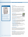
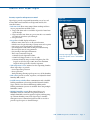
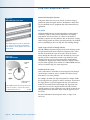
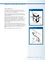
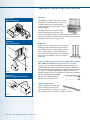
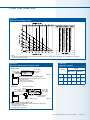
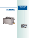
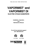
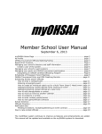
Vapormis t
®
Electric-to-Stea m
Humidification Sy s t e m
PR0DUCT CATALOG
Easy to install and maintain
Figure -1:
Matching dispersion cabinet
Installs in a snap!
The Vapormist® humidifier is a compact, cabinet-style humidifier
with a history of reliably and efficiently providing humidification
steam.
Installation is a snap — just attach the frame to a supporting
structure and connect the services. Maintenance is easy, too.
Remove the resin cover and all components are accessible for
service. The permanent, stainless steel vaporizing chamber and the
use of softened water eliminate the need for service for up to three
years. Its non-corrosive enclosure will never rust, and years later
will look as good as it did out of the box.
DRI-STEEM® offers two dispersion units that
match the Vapormist cabinet: the SDU-I and
the SDU-E. The SDU-I (Steam Distribution
Unit Internal Absorption) disperses steam
without a visible vapor trail. This option
is ideal for spaces where the presence of
vapor creates either a visual problem or
a condensation risk. For larger capacities,
choose the SDU-E (Space Distribution Unit
External Absorption). Both SDU models offer
extremely quiet, reliable steam distribution.
Vapor-logic3 control
Vapormist features Vapor-logic®3, DRI-STEEM’s stateof-the-art controller. Vapor-logic3 offers precise and
complete humidifier control, and is so easy to use
it practically runs itself!
On-off, TP or SSR control. Choose from standard modulation for
superior control in most environments, or add the solid state relay
(SSR) option to achieve even tighter control.
Superior control capabilities. Key features of this modular
controller include:
• PID control provides accurate, responsive, adjustable RH control
• The temperature sensor enables the controller to hold water at a
preset temperature allowing rapid response to a call for humidity
• Data reports help you monitor humidifier performance
• Backlit display is easy to read
• Menus are intuitive and easy to navigate
• Real-time clock allows time-stamped alarm tracking and the
ability to program draining for preset times
• LonTalk® interoperability allows communication with a LonTalk
building automation system
• Multiple-humidifier control allows control of up to 16
humidifiers with one controller
Aesthetically pleasing
Not only does the Vapormist work well, it looks great too! It has an
attractive resin cover, and the Vapor-logic3 keypad, which mounts
directly on the humidifier, adds to the polished look and makes the
Vapormist a perfect choice for finished-space applications.
Easy to maintain
Even the best humidifiers require periodic maintenance to ensure
optimal performance, so we’ve made it easy for you. The Vapormist
cover is completely removable, giving you easy access to the
unit for all maintenance procedures. Our redesigned tank keeps
maintenance to a minimum and offers the option of localized
cleaning or tank removal for remote cleaning.
P a g e • D R I - S T E E M Va p o r m i s t h u m i d i f i e r
Va p o r m i s t f e a t u r e s
Proven performance
Guaranteed absorption
• Control to ±3% RH
• Electronically monitored water level ensures safe and reliable
operation
• Diagnostic test at unit start-up verifies system performance
• Cataloged and guaranteed steam
absorption distances
• Unique tubelets in dispersion tubes
eliminate condensate drips
• Published absorption tables for sizing and
selecting the correct dispersion option
• Dri-calc® software available for computer
calculation of absorption distances and
system selection
Application flexibility
• Capacity range up to 102 lbs/hr (46 kg/h) for each unit
• Capacity up to 1632 lbs/hr (734 kg/h) using multiple-humidifier
control option (link up to 16 humidifiers)
• Supports all types of water: tap, softened, reverse osmosis or
deionized; easy to field-convert if water type changes
• Attractive enclosure suitable for finished spaces
• Disperses steam through ductwork using single or multiple tubes,
Rapid-sorb® or Ultra-sorb® dispersion units, or disperses steam
directly into a space using Space Distribution Units (SDU-E or
SDU-I), enclosed fan units that mount on top of the Vapormist or
remotely within a room
• The Space Distribution Unit Internal Absorption (SDU-I)
disperses humidity with no visible vapor trail, making it ideal for
use in finished spaces
Minimal maintenance
• Removable cover allows easy access to evaporating chamber and
electrical connections
• Use of softened water significantly reduces maintenance
requirements
• End-of-season autodrain minimizes microbial growth
• User-adjustable water skimmer skims off floating minerals
• Controller-operated drain and flush removes precipitated
minerals from evaporating chamber
• Constant thermal expansion and contraction of heating elements
continuously sheds mineral buildup
• Three levels of heater protection prevent premature failure
• Easy water level control access
Advanced control with Vapor-logic3
• User-programmable for on-off, time-proportioning, or solid state
relay (SSR) control
• Easy-to-use keypad displays current conditions, alarm log,
graphed data, and message reminder for tank cleaning based on
water usage
• Temperature sensor enables freeze-protection and allows rapid
warm-up
• Years of proven performance ensures trouble-free operation
• Cold-snap offset option prevents window condensation
• VAV control option
• Accepts all input signals
• Interoperable with any LonTalk network (not available with
multiple-humidifier control)
D R I - S T E E M Va p o r m i s t h u m i d i f i e r • P a g e Va p o r m i s t c o m p o n e n t s
Figure -1:
Water level control for standard
water systems
Figure -2:
Vapormist components
5
6
4
7 2
3
Fill valve closes
1
Fill valve opens
Low-water cutoff
Systems using tap or softened water control
water levels electronically using a threerod probe. The controller responds with the
above actions when the water level reaches
each rod.
OM-402-2
VLC-OM-030
1. Control cabinet
The Vapor-logic3 controller controls all functions of the
humidifier. See Page 7 for more information.
2. Water level control
Tap or softened water systems control water levels electronically
using a three-rod probe (Figure 4-1). DI/RO water systems
control water levels using a float valve (shown on next page) and
low-water cutoff switch.
3. Drain
Duration and frequency of draining can be adjusted through
the keypad. To avoid possible stagnant water and microbial
growth, the humidifier automatically drains if there is no call for
humidity after a user-defined time period (72 hour default).
4. Water skimmer/overflow port
P a g e • D R I - S T E E M Va p o r m i s t h u m i d i f i e r
In standard water systems, the water skimmer reduces surface
minerals in the evaporating chamber. Skimming occurs each
time the humidifier fills. The skim time duration is useradjustable. DI/RO water systems do not require skimming. In
DI/RO systems, the skimmer port functions as an overflow port.
Va p o r m i s t c o m p o n e n t s
5. Heating elements
Low-watt-density Incoloy-sheathed heating elements ensure
operation for many seasons. Constant expansion and contraction
of heating elements sheds mineral scale. In the unlikely event of
heater failure, heating elements can be removed easily.
6. Removable cover
A removable cover allows easy access to the evaporating chamber, electrical connections, and drain.
Figure -1:
Water level control for DI/RO
water systems
Supply water connection
Float ball
Float rod
7. Steam outlet
Steam generated in the unit rises and exits through the steam
outlet and travels to the dispersion unit through either vapor
hose or piping.
8. Temperature sensor (not shown)
Mounted on the evaporating chamber, this sensor enables:
• Over-temperature protection
• Freeze protection
• Preheating, allowing rapid response to a call for humidity
Systems using deionized (DI) water or water
that has been treated through reverse
osmosis (RO) control water levels using a
float valve and low water cutoff switch.
OM-7396
D R I - S T E E M Va p o r m i s t h u m i d i f i e r • P a g e Va p o r m i s t p r i n c i p l e o f o p e r a t i o n
Figure -1:
Vapormist principle of operation
Standard water system (shown with cover removed)
1
4
3
2
OM-2000
1. When the system is first activated, the fill valve opens and the
evaporating chamber fills with water to the operating level.
2. On a call for humidity, the heating elements are energized,
causing the water to boil. The fill valve opens and closes as
needed to maintain the operating water level.
3. During refill in standard water systems, a portion of the surface
water is skimmed off, carrying away precipitated minerals.
(DI/RO systems do not require skimming.)
4. Steam created in the evaporating chamber flows through vapor
hose or piping to the dispersion assembly, where it is discharged
into the airstream.
P a g e • D R I - S T E E M Va p o r m i s t h u m i d i f i e r
C o n t r o l w i t h Va p o r- l o g i c 3
Accurate, responsive microprocessor control
Vapor-logic3 provides exceptional functionality, ease of use, and
accurate RH control. Standard on all Vapormist models, this
controller features:
Figure -1:
Vapor-logic3 keypad
• Real-time clock allows time-stamped alarm tracking and three
ways to program drain and flush cycles:
1. Usage (unit drains after a set number of pounds of water have
cycled through)
2. Usage and time (unit drains at a preset time after a set number
of pounds of water have cycled through)
3. At a preset time
• Keypad has a backlit display and features:
– Intuitive menu-driven access to all system functions
– Default screen for quick viewing of system status and set points
– Data reports to track performance and efficiency
– System diagnostics and alarm tracking for troubleshooting
– Password protection of setup parameters
– Easy viewing in low-light environments
– Three ways to mount the keypad:
1. Mounted on the Vapormist cabinet
2. Hand-held; shipped with a 5' (1.5 m) cable
3. Mounted remotely using a standard telephone plate. The
keypad can be located up to 500' (152 m; the maximum
length of the keypad cable) from the Vapormist.
The Vapor-logic3 keypad is easy to use and
read, and it provides access to all humidifier
functions.
• Tank temperature sensor, mounted on the evaporating chamber,
allows Vapor-logic3 to provide:
– Over-temperature protection
– Freeze protection
– Tank preheating, allowing rapid response to a call for humidity
• PID control provides accurate, responsive, and adjustable relative humidity (RH) control.
• LonTalk interoperability allows communication with a LonTalk
building automation system using Standard Network Variable
Types (SNVTs). Note that LonTalk interoperability with a
building automation system is not available when using multiple
humidifier control.
• Multiple-humidifier control allows control of up to 16
humidifiers with one controller. The primary benefit of
multiple-humidifier control is expanded capacity without giving
up consistent humidity control. The Vapor‑logic3 controller
anticipates increased demand and preheats tanks as needed to
provide a rapid response to demand changes.
D R I - S T E E M Va p o r m i s t h u m i d i f i e r • P a g e Drip-free dispersion basics
Guaranteed absorption distances
Figure -1:
DRI-STEEM dispersion tubes
Using data collected in our on-site test lab, we have developed
guaranteed steam absorption distances. Performance charts allow
you to confidently choose equipment that will accommodate any
application.
Dry steam
DRI-STEEM’s dispersion tubes are fitted with
one or two rows of closely-spaced thermalresin tubelets to evenly disperse steam across
the airstream.
Figure -2:
DRI-STEEM tubelets
Calibrated
orifice
Tubelet
Adding humidification to an airstream without creating wetness
in the duct system is critical for the maintenance of a healthy
environment. Wet areas in ducts are a threat to the health of
building occupants since they moisten dust on duct floors, creating
ideal breeding grounds for disease-producing microbes. In addition,
water accumulating in ducts can drip and cause building damage.
Steam escapes drip-free through tubelets
All DRI-STEEM evaporative dispersion tube units discharge steam
through thermal-resin tubelets fitted into dispersion tubes. These
tubelets extend from the center of the tube, where the steam is
driest, through the tube wall, to the duct airstream. In essence, the
tubelets provide a temperature-neutral escape tunnel for steam,
allowing steam to cross over lower-temperature metal without
condensing or dripping. Each tubelet contains a calibrated orifice
sized for steam capacity. These tubelets are a DRI-STEEM exclusive,
and are essential for drip-free steam dispersion.
Condensate drains away
Some condensation is inevitable in steam dispersion, but through
careful design, condensate can be controlled and directed away
from where it can cause problems.
Air flow
Condensate clings
to inner wall
DRI-STEEM’s unique tubelets extend into the
center of the tube so only the driest steam
is discharged into the air.
150-3bw
For example, the Ultra-sorb dispersion panel has a unique doubleheader design that uses gravity to remove condensate. Steam enters
the supply header, escapes through the tubelets, and condensate
drains out the return header. In the Rapid-sorb dispersion unit,
steam enters one end of a single bottom header with velocities
carefully managed so that condensate is not pushed out into the air
along with the steam, but rather drains out at the opposite end of
the header.
For more information about dispersion units, see Pages 9-10
and 16-23.
P a g e • D R I - S T E E M Va p o r m i s t h u m i d i f i e r
Va p o r m i s t s t e a m d i s p e r s i o n o p t i o n s
Space Distribution Units
Space Distribution Units (SDUs), designed for use in finished
spaces, disperse steam into large open spaces and are particularly
useful where there are no air-handling ducts.
Figure -1:
SDU-E
There are two SDU models: SDU-I (steam absorbs within the
enclosure with no visible vapor) and SDU-E (visible steam absorbs
outside the enclosure).
The SDU-I fan mixes room air and steam to ensure complete
absorption before discharge as humidified air. The SDU-I is
available for models VM-2 through VM-8, and all VM-10 models
except those using 240V, three-phase power with SSR control.
Note: Maximum ambient RH must not exceed 45% for the SDU-I
to operate properly.
The Space Distribution Unit External Absorption (SDU-E) is
designed for higher capacity dispersion. The SDU-E is available for
all models except those models using 240V/480V/600V/three-phase
power with the SSR control option and drawing more than 21.7
amps.
For more information about SDUs, see Page 22 and 23.
SDU shown mounted directly above the Vapormist
OM-55-1
Figure -2:
SDU mounted remotely
OM-56-1
D R I - S T E E M Va p o r m i s t h u m i d i f i e r • P a g e Va p o r m i s t s t e a m d i s p e r s i o n o p t i o n s
Figure 10-1:
Ultra-sorb dispersion
OM-636-1
Figure 10-2:
Rapid-sorb dispersion
Ultra-sorb
The multiple-tube Ultra-sorb allows virtually
instantaneous steam absorption. The factoryassembled panel can be installed within
inches upstream of dampers, coils or elbows
without dripping.
The Ultra-sorb’s steam downflow design
allows for high capacity dispersion. The
unit is preassembled at the factory within a mounting frame, and
installs easily. Simply mount the panel and complete the steam and
condensate connections (see Pages 16-18).
Rapid-sorb
Rapid-sorb has a single header design with steam
flowing up from a bottom header. This design is
an excellent choice for medium capacity systems
where multiple tubes are needed to handle the
load and/or when non-wetting distance is limited.
Rapid-sorbs are assembled on-site (see Pages 16
and 19-20).
OM-637-1
Figure 10-3:
Single- or multiple-tube dispersion
Reduce wasted energy by up to 85% with High-efficiency tubes
DRI-STEEM's PVDF insulated dispersion tubes reduce wasted
energy by up to 85% while significantly reducing airstream heat
gain and dispersion-generated condensate production. Insulating
the dispersion tubes makes more steam available for dispersion, and
less is lost to condensate. High-efficiency dispersion tubes are an
available option for Ultra-sorb and Rapid‑sorb dispersion assemblies.
For more information, see the Highefficieny Tube option brochure,
available at www.dristeem.com
Single or multiple tubes
Single or multiple dispersion tubes
are an excellent choice for lower
capacity applications or where there is room
for a longer non-wetting distance (see Pages 16 and 21).
OM-82-1
P a g e 1 0 • D R I - S T E E M Va p o r m i s t h u m i d i f i e r
Va p o r m i s t s p e c i f i c a t i o n s
Table 11-1:
Vapormist specifications, capacities, and weights
Model
Current draw (amps)
Maximum steam
capacity
Single-phase
Weights ‡
Three-phase
Shipping
Operating
kW
lbs/hr
kg/h
120V
208V*
240V*
480V†
600V†
208V*
240V†
480V†
600V†
lbs
kg
lbs
kg
2
6
2.7
16.7
9.6
8.3
4.2
3.3
—
—
—
—
80
36
95
43
4
12
5.4
33.3
19.2
16.7
8.3
6.7
16.7**
14.4**
7.2**
5.8**
80
36
95
43
6
18
8.2
—
28.8
25.0
12.5
10.0
25.0**
21.7**
10.8**
8.7**
88
40
122
55
8
24
10.9
—
38.5
33.3
16.7
13.3
33.3**
28.9**
14.4**
11.5**
88
40
122
55
10
30
13.6
—
—
41.7
20.8
16.7
29.1**
25.3**
12.6**
10.1**
93
42
139
63
12
36
16.3
—
—
—
25.0
20.0
33.3
28.9
14.4
11.5
93
42
139
63
14
42
19.1
—
—
—
29.2
23.3
38.9
33.7
16.8
13.5
93
42
139
63
16
48
21.8
—
—
—
33.3
26.7
44.4
38.5
19.2
15.4
93
42
139
63
21
63
28.6
—
—
—
43.8
35.0
—
—
25.3
20.2
95
43
152
69
25
75
34.0
—
—
—
—
41.7
—
—
30.1
24.1
95
43
152
69
30
90
40.9
—
—
—
—
—
—
—
36.1
28.9
101
46
156
71
34
102
46.3
—
—
—
—
—
—
—
40.9
32.7
101
46
156
71
Notes:
* On 208V/240V/single-phase/three-wire and on 208V/three-phase/four-wire supplies, the neutral line provides a separate 120V circuit for the SDU fan unit.
** For wire sizing, the highest leg draw is shown due to current imbalance.
† Add the following to Vapormist weights if using an SDU option (these weights are for additional control components housed within the Vapormist cabinet):
– SDU-I: 12 lbs (5.5 kg)
– SDU-E: 9 lbs (4 kg)
See the SDU weights Table 11-2 below for SDU weights (shipped separately).
‡ Add the following if using the SSR option:
– For single-phase or three-phase models drawing less than 21.7 amps, add 2 lbs (1 kg)
– For three-phase models drawing more than 21.7 amps, add 4 lbs (2 kg)
All Vapormists operate at 50/60 Hz.
Notes about SDUs (Space Distribution
Units):
Table 11-2:
Space Distribution Unit specifications**
Maximum
capacity
Shipping
weight
lbs/hr
kg/h
lbs
kg
Amps at
120V
(50/60 Hz)
SDU-E
102
46.3
61
28
2.07
1/8
545
0.26
64
SDU-I
30
13.6
68
31
3.20
1/5
760
0.36
58
SDU
model
Horsepower
cfm
m3/s
dB*
Notes:
* Measurement taken 6.5' (2 m) in front of SDU cabinet.
**For visible vapor to be absorbed completely within the SDU-I unit before being
discharged as humidified air, room air must be 45% RH or less. Trying to maintain
greater than 45% RH will cause visible vapor and potential for moisture collection
on the discharge grille.
• The SDU-I is available for models VM-2
through VM-8, and all VM-10 models
except those using 240V, three-phase
power with SSR control.
• The SDU-E is available for all Vapormist
models except those models using
240V/480V/600V/three-phase power with
the SSR control option and drawing more
than 21.7 amps.
• SDUs ship separately from the Vapormist.
D R I - S T E E M Va p o r m i s t h u m i d i f i e r • P a g e 1 1
Va p o r m i s t d i m e n s i o n s
Figure 12-1:
Dimensions
24.2"
(614 mm)
Top view
2" (50 mm)
10.9"
(276 mm)
2" (50 mm)
1" (25 mm)
2.25" (57 mm)
Power wiring knockout
Steam outlet
Control or SDU wiring knockout
Venting
Front view
Left side view
18.6"
(472 mm)
1.50" (38 mm)
2.25" (57 mm)
¾" pipe thread (DN20) frame drain
5.75" (146 mm)
16.1"
(409 mm)
¾" pipe thread (DN20) tank drain
Bottom view
0.50" (13 mm) hole in
base for water fill line
0.75" (19 mm)
0.63"
(16 mm)
2.25" (57 mm)
Power wire knockout
1.50" (38 mm)
5.75" (146 mm)
24.2"
(614 mm)
P a g e 1 2 • D R I - S T E E M Va p o r m i s t h u m i d i f i e r
Control wiring knockout
DC-1167
Va p o r m i s t m o u n t i n g
Vapormist and SDU mounting
Figure 13-1:
Vapormist with an SDU-I
Keyhole for 3/8" dia.
(M10) fasteners
Mount the Vapormist and SDU to wall studs
using the template on the box. Two lag bolts
are provided with each unit.
16"
(406 mm)
SDU
chassis
SDUs can be mounted directly above the
Vapormist cabinet (as shown at left) or
remotely. Maintain clearances as shown
below. Provide at least 6" (152 mm)
clearance on each side of an SDU when
mounted remotely. For SDU-E clearances
see also Table 22-1: SDU-E minimum nonwetting distances.
3" (76 mm)
18.02"
(458 mm)
17.75"
(451 mm)
16"
(406 mm)
0.25"
(6.4 mm)
3" (76 mm)
Keyhole for 3/8" dia.
(M10) fasteners
Note that the SDU-E dispersion box requires
an installed condensate drain line. See Page
23 for more information.
18.50"
(470 mm)
Vapormist
chassis
24"
(610 mm)
OM-282-4
Figure 13-3:
Clearance recommendations
Figure 13-2:
Vapormist with an SDU-E
Keyhole for 3/8" dia.
(M10) fasteners
16"
(406 mm)
To dispersion
assembly
SDU chassis
16"
(406 mm)
18.02"
(458 mm)
Right side
electrical controls:
36" (915 mm)
Supporting
wall
Secured to
supporting
wall
3" (76 mm)
Left side:
12" (305 mm)
Front 36"
(915 mm)
Floor: 24" (610 mm)
16"
(406 mm)
2" (51 mm)
3" (76 mm)
Keyhole for 3/8" dia.
(M10) fasteners
Top (when SDU is not mounted
directly above the Vapormist):
18"(460 mm)
DC-1201
18.5"
(470 mm)
Vapormist
chassis
24"
(610 mm)
OM-282-7
D R I - S T E E M Va p o r m i s t h u m i d i f i e r • P a g e 1 3
Va p o r m i s t p i p i n g ,
standard water models
Figure 14-1:
Vapormist (standard water models) field piping overview
Water supply line; water pressure must be
between 25 psi and 80 psi (175 kPa and
550 kPa); water conductivity minimum
100 µS/cm. If water piping to humidifier is
nonmetallic, we recommend that the first
3' (1 m) of water supply piping from the
humidifier be metallic
Steam vapor hose (maximum
run 10' [3 m]). May also use pipe
or tubing. See the DRI-STEEM
Design Guide for maximum pipe
or tubing lengths.
Electrical conduit
knockouts provided
top and bottom:
• Combination, for
½" and ¾" conduit
connectors (knockout diameters
22.3 mm and
28.6 mm)
• Combination, for
¾" and 1" conduit
connectors (knockout diameters
28.6 mm and
34.9 mm)
Two keyholes for wall
mounting, 16" (406 mm)
on center
Water supply line
Unions by installer
2" (50 mm) water seal or loop
in the supply line to isolate
steam from nonmetallic supply
piping
Shock arrester
recommended to
reduce water hammer
¾" pipe thread
(DN20) tank drain,
skimmer and P-trap
piping, rated for
212 °F (100 °C). If
piping run is over
10' (3 m) increase
pipe to 1¼" (DN32)
after P-trap.
Install plumb
12" (300 mm)
2" (50 mm)
1" (25 mm) air gap
Cover
Spill funnel. Plumb
to floor drain.
Frame drain
Open drain required. See
first note below.
¾" pipe thread (DN20)
frame drain and
P-trap piping, rated
for 212 °F (100 °C)
DC-1136
Notes:
• Locate air gap only in spaces with adequate temperature and air movement to absorb flash steam; otherwise, condensation may form on nearby surfaces.
Refer to governing codes for drain pipe size and maximum discharge water temperature.
• Offset humidifier from spill funnel or floor drain to prevent flash steam from rising into the cabinet.
• Dashed lines indicate provided by installer.
• The water supply inlet is more than 1" (25 mm) above the skim/overflow port, eliminating the possibility of backflow or siphoning from the tank. No additional
backflow prevention is required; however, governing codes prevail.
• Install a union in the water supply and drain lines as shown to allow tank removal.
• Damage caused by chloride corrosion is not covered by your DRI-STEEM warranty.
• See the next page for recommended piping for Vapormist-DI models (models that use DI/RO water).
• See the dispersion section of this manual for more information about piping that connects the humidifier to the dispersion assembly.
P a g e 1 4 • D R I - S T E E M Va p o r m i s t h u m i d i f i e r
Va p o r m i s t p i p i n g ,
DI/RO water models
Figure 15-1:
Vapormist-DI (deionized/reverse osmosis water models) field piping overview
Steam vapor hose (maximum
run 10' [3 m]). May also use pipe
or tubing. See the DRI-STEEM
Design Guide for maximum pipe
or tubing lengths.
Water supply line; water pressure must
be between 25 psi and 80 psi (175 kPa
and 550 kPa)
Two keyholes for wall mounting,
16" (406 mm) on center
Unions by installer
Strainer,
by installer
First 3' (1 m) of
water supply line is
recommended to be
stainless steel tubing with
a 2" (50 mm) water seal
or loop in the supply line
to isolate steam from
nonmetallic supply piping.
¾" pipe thread
(DN20) tank drain,
and P-trap piping,
rated for 212 °F
(100 °C). If piping
run is over 10'
(3 m) increase pipe
to 1¼" (DN32)
after P-trap.
Install plumb
Electrical conduit
knockouts provided
top and bottom:
• Combination, for
½" and ¾" conduit
connectors (knockout diameters 22.3
mm and 28.6 mm)
• Combination, for
¾" and 1" conduit
connectors (knockout diameters 28.6
mm and 34.9 mm)
12" (300 mm)
2" (50 mm)
1" (25 mm)
air gap
Frame drain
Spill funnel. Plumb
to floor drain
Open drain required. See
first note below.
¾" pipe thread (DN20)
frame drain and
P-trap piping, rated
for 212 °F (100 °C)
Cover
DC-1139
Notes:
• Locate air gap only in spaces with adequate temperature and air movement to absorb flash steam; otherwise, condensation may form on nearby surfaces.
Refer to governing codes for drain pipe size and maximum discharge water temperature.
• Offset humidifier from spill funnel or floor drain to prevent flash steam from rising into the cabinet.
• Dashed lines indicate provided by installer.
• The water supply inlet is more than 1" (25 mm) above the overflow port, eliminating the possibility of backflow or siphoning from the tank. No additional
backflow prevention is required; however, governing codes prevail.
• Install a union in the water supply and drain lines as shown to allow tank removal.
• Damage caused by chloride corrosion is not covered by our DRI-STEEM warranty.
• See the previous page for recommended piping for Vapormist standard water models.
• See the dispersion section of this manual for more information about piping that connects the humidifier to the dispersion assembly.
D R I - S T E E M Va p o r m i s t h u m i d i f i e r • P a g e 1 5
Calculating non-wetting distances
Notes:
Sample exercise
• Final equipment selection should account
for condensate loss. See the DRI-STEEM
Design Guide for steam loss tables.
• Dispersion assembly should accommodate
maximum output capacity of humidifier.
To learn more about how to specify a dispersion unit based on nonwetting distance, read the sample problem below. For purposes of
this sample problem, assume you have chosen to use Ultra-sorb
units because you want pre-assembled panels.
Assume the air entering the dispersion assembly is 20% RH and the
air leaving the zone of humidification needs to be 70% RH. Design
for a non-wetting distance of 24" (610 mm) maximum.
Solution
Refer to the graph on Page 17: Ultra-sorb non-wetting distances.
Find 20% entering RH. Proceed vertically until you intersect the
70% leaving RH line. Draw a line horizontally from that point to
the right to see that for 24" (610 mm) of non-wetting distance, 6"
(152 mm) tube spacing would be the closest match.
Verify capacity
From Table 17-1: Ultra-sorb tube spacing and capacity on
Page 17, note that for 6" (152 mm) spacing, maximum capacity is
18 lbs/hr/ft2 (88 kg/h/m2). Multiply this value by the active face
area of the Ultra-sorb to determine if the unit will produce adequate
output capacity. If the capacity is inadequate, go to the next smaller
tube spacing.
Steam absorption considerations
1. Non-wetting distance is the dimension downstream from the
leaving side of the steam dispersion assembly to the point where
wetting will not occur, although wisps of steam may be present.
Solid objects at duct air temperature, such as coils, dampers,
fans, etc., downstream of this dimension will remain dry.
2. C A U T I O N ! Non-wetting distances described in this catalog
do not apply when installing a steam dispersion assembly
upstream of filter media. If you need to install a steam dispersion
assembly upstream of filter media, consult your representative or
DRI‑STEEM directly for special recommendations.
3. Note that the rise (Δ) in RH (the difference between entering and
leaving RH) has a direct bearing on the non-wetting distance. As
the rise increases, more vapor needs to be dispersed into the air,
and thus the non-wetting distance increases.
4. Uneven airflow over the cross-section of a dispersion assembly
can result in nonuniform mixing of steam with air which, in
turn, will adversely affect the non-wetting distance.
P a g e 1 6 • D R I - S T E E M Va p o r m i s t h u m i d i f i e r
Ultra-sorb dispersion
Figure 17-1:
Ultra-sorb non-wetting distances
3"
6"
9"
12"
Note:
The above non-wetting data applies to all air velocities up to 2,000 fpm (10.2 m/s), and is based on air leaving the zone of humidification at conditions of
55 °F (13 °C) and the stated % RH. The blue lines in the graph refer to the sample exercise described on Page 16.
Table 17-1:
Ultra-sorb tube spacing and capacity
Tube spacing
Maximum capacity
inches
mm
lbs/hr/ft2
kg/h/m2
3
76
36
175
6
152
18
88
9
229
12
59
12
305
9
44
Note:
The above steam flow capacity data is based on pounds (kg) of steam per hour per square
foot (meter) of face area, exclusive of headers, at various tube spacings.
D R I - S T E E M Va p o r m i s t h u m i d i f i e r • P a g e 1 7
Ultra-sorb dimensions
Figure 18-1:
Ultra-sorb Model LV dimensions
E
A'
G
Supply header
Dispersion tubes
Top view
G
Header enclosure
C
Mounting flange
F
B
Header
B'
Condensate header
D
A
Elevation view
Header
H
E
Side view
OM-123us
Table 18-1:
Ultra-sorb Model LV dimensions
Dimension
Description
Inches (mm)
A
Overall width
15" (381) minimum to 147" (3734) maximum in 1" (25) increments
A'
Face width
12" (305) minimum to 144" (3658) maximum in 1" (25) increments
B
Overall height
21" (533) minimum to 156" (3962) maximum in 1" (25) increments
B'
Face height
12" (305) minimum to 144" (3658) maximum in 1" (25) increments
C
Steam inlet diameter
Determined by maximum capacity
D
Condensate drain
¾" pipe thread (DN20)
E
Header enclosure (front to back)
For 3" (76) and 4" (102) headers, E = 5" (127); for 5" (127) header, E = 6" (152); for 6" (152) header,
E = 7" (178)
F
Header enclosure (top to bottom)
For 3" (76) header F = 4.5" (114); for 4" (102) header, F = 5.5" (140); for 5" (127) header, F = 6.5" (165);
for 6" (152) header F = 7.5" (191)
G
Flange
1.5" (38)
H
Condensate header enclosure
4.5" (114)
Notes:
• Header diameter varies with capacity.
P a g e 1 8 • D R I - S T E E M Va p o r m i s t h u m i d i f i e r
Rapid-sorb dispersion
Figure 19-1:
Rapid-sorb non-wetting distances
6"
9"
12"
18"
24"
Note:
The above non-wetting data applies to all air velocities up to 2,000 fpm (10.2 m/s), and is based on air leaving the zone of humidification at conditions of
55 °F (13 °C) and the stated % RH.
Table 19-1:
Rapid-sorb header capacities
Header capacity
Table 19-2:
Rapid-sorb dispersion tube capacities*
Header diameter
Tube capacity
Tube diameter
lbs/hr
kg/h
inches
DN
lbs/hr
kg/h
inches
DN
≤250
≤113
2
50
≤35
≤16
1½
40
251-500
114-227
3
80
36-70
17-32
2
50
501-800
228-363
4
100
Note:
* If duct height is <15" (381 mm), tube quantities may need to increase to compensate
for reduced capacity of short tubes. Consult DRI-STEEM or see Dri-calc for the correct
calculation.
D R I - S T E E M Va p o r m i s t h u m i d i f i e r • P a g e 1 9
Rapid-sorb dimensions
Figure 20-1:
Rapid-sorb dimensions
A
E
1½" (DN40) dia. dispersion tubes
use slip coupling
B
2" (DN50) dia. dispersion tubes
use hose cuff and clamps
Header outside duct
C
Pitch header toward drain
Escutcheon plate
F
Header inside duct or AHU
D
OM-3005
Note:
Add water seal to condensate drain as shown in the Dri-calc Installation Guides or the Vapormist Installation, Operation and Maintenance manual.
Table 20-1:
Rapid-sorb dimensions
Dimension
Description
Inches (mm)
A
Face width
12" (305) minimum to 120" (3048) maximum in 1" (25) increments
B
Face height
12" (305) minimum to 120" (3048) maximum in 1" (25) increments
C
Steam inlet
Determined by supply steam pressure
D
Condensate drain
¾" pipe thread (DN20)
E
Distance from tube center to inside of duct or AHU wall
4.5" (114) minimum
F
Distance from outside of duct or AHU wall to end of
Rapid-sorb leader
4.5" (114) minimum
Note:
All Rapid-sorb units are custom-sized and field-assembled to fit the duct or air handler. Consult DRI-STEEM for sizes larger or smaller than those listed above.
P a g e 2 0 • D R I - S T E E M Va p o r m i s t h u m i d i f i e r
Single tube dispersion
Figure 21-1:
Single tube non-wetting distances
18"
12"
9"
24"
Note:
The above non-wetting data applies to all air velocities up to 2,000 fpm (10.2 m/s), and is based on air leaving the zone of humidification at conditions of
55 °F (13 °C) and the stated % RH.
Figure 21-2:
Single tube without and with condensate drain
Capacity
Without drain
Pitch: See Notes
Table 21-1:
Single tube capacities
Pitch 2"/ft (15%)
Tube size
4.5" (114 mm)
minimum from
top of duct
Without drain
OM-496A
Notes for single tube without condensate drain:
Recommended pitch toward humidifier for interconnecting
hose, tubing or pipe:
• Vapor hose: 2" per ft (15%)
• Tubing or pipe: 1/8" per ft (1%)
With drain
Pitch: See Notes
4.5" (114 mm) minimum
from top
Pitch 1/8"/ft (1%)
of duct
6"
(152 mm)
5" (127 mm)
With drain
inches
DN
lbs/hr
kg/h
lbs/hr
kg/h
1½
40
28.4
13
56.8
25.8
2
50
56.8
25.8
85.2
38.6
4.5" (114 mm)
minimum from
bottom of duct
Condensate drain.
Pitch ¼"/ft (2%)
1" (25 mm) air gap
OM-496B
Notes for single tube with condensate drain:
Recommended pitch toward humidifier for interconnecting hose, tubing or pipe:
• Vapor hose: 2" per ft (15%)
• 1½" tubing or pipe: ½" per ft (5%)
• 2" tubing or pipe: ¼" per ft (2%)
D R I - S T E E M Va p o r m i s t h u m i d i f i e r • P a g e 2 1
Space Distribution Unit dispersion
As steam is discharged from the SDU-E, it quickly cools and turns
to a visible fog that is lighter than air. As this fog is carried away
from the SDU-E by the airstream, it tends to rise toward the ceiling.
If this fog contacts solid surfaces (columns, beams, ceiling, pipes,
etc.) before it disappears, it can collect and drip as water. The
greater the space relative humidity, the more the fog will rise, throw
and spread.
Figure 22-1:
SDU-E rise, spread and throw
Steam outlet
Air intake
grille
Rise
The table below lists the minimum rise, throw and spread nonwetting distances for SDU-E area-type humidifiers at 40%, 50% and
60% RH in the space. Surfaces cooler than ambient temperature,
or objects located within this minimum dimension, can cause
condensation and dripping. To avoid steam impingement on
surrounding areas, observe the minimum non-wetting distances in
the table below.
Throw
Spread
DC-1027
See also the Space Distribution Unit
specifications table on Page 11.
The SDU-E contains a 545 cfm (0.26 m3/s) blower (120 V, singlephase, 60 Hz) and an airflow proving switch field-wired to the
Vapormist humidifier electrical panel. A wiring diagram of the
SDU-E is included with the unit.
On a call for humidity, the humidifier begins producing steam
and the start relay energizes the SDU-E blower. When the call for
humidity is satisfied, the Vapor-logic3 microprocessor keeps the
blower running to disperse residual moisture using a time delay.
Table 22-1:
SDU-E minimum non-wetting distances
40% RH @ 70 °F (21 °C)
Model
Rise
Throw
50% RH @ 70 °F (21 °C)
Spread
Rise
Throw
60% RH @ 70 °F (21 °C)
Spread
Rise
Throw
Spread
ft
m
ft
m
ft
m
ft
m
ft
m
ft
m
ft
m
ft
m
ft
m
VM-2
1.0
0.3
5.0
1.5
1.0
0.3
1.5
0.5
6.5
2.0
1.5
0.5
2.5
0.8
7.5
2.3
2.5
0.8
VM-4
1.0
0.3
5.0
1.5
1.0
0.3
1.5
0.5
6.5
2.0
1.5
0.5
2.5
0.8
7.5
2.3
2.5
0.8
VM-6
1.0
0.3
5.0
1.5
1.0
0.3
1.5
0.5
6.5
2.0
1.5
0.5
2.5
0.8
7.5
2.3
2.5
0.8
VM-8
1.0
0.3
5.5
1.7
1.0
0.3
1.5
0.5
6.5
2.0
1.5
0.5
2.5
0.8
7.5
2.3
2.5
0.8
VM-10
1.5
0.5
6.0
1.8
1.5
0.5
2.0
0.6
7.0
2.1
2.0
0.6
3.0
1.0
8.0
2.5
3.0
1.0
VM-12
1.5
0.5
6.0
1.8
1.5
0.5
2.0
0.6
7.0
2.1
2.0
0.6
3.0
1.0
8.0
2.5
3.0
1.0
VM-14
2.0
0.6
7.0
2.1
2.0
0.6
2.0
0.6
7.0
2.1
2.0
0.6
3.0
1.0
9.0
2.7
3.0
1.0
VM-16
2.0
0.6
7.0
2.1
2.0
0.6
2.0
0.6
7.0
2.1
2.0
0.6
3.0
1.0
9.0
2.7
3.0
1.0
VM-21
2.0
0.6
7.5
2.3
2.0
0.6
2.5
0.8
10.0
3.0
2.5
0.8
3.0
1.0
12.0
3.7
3.0
1.0
VM-25
2.0
0.6
8.0
2.5
2.0
0.6
2.5
0.8
10.5
3.2
2.5
0.8
3.5
1.1
12.5
3.8
3.5
1.1
VM-30
2.0
0.6
8.0
2.5
2.0
0.6
2.5
0.8
10.5
3.2
2.5
0.8
3.5
1.1
12.5
3.8
3.5
1.1
VM-34
2.0
0.6
8.0
2.5
2.0
0.6
2.5
0.8
10.5
3.2
2.5
0.8
3.5
1.1
12.5
3.8
3.5
1.1
Notes:
Rise:
Minimum non-wetting height above the steam outlet of the SDU-E
Throw: Minimum non-wetting horizontal distance from the steam outlet of the SDU-E.
Spread: Minimum non-wetting width from the steam outlet of the SDU-E.
P a g e 22 • D R I - S T E E M V a p o r m i s t h u m i d i f i e r
Space Distribution Unit dispersion
Figure 23-1:
SDU-I mechanical detail
Figure 23-3:
SDU-E drain line piping
Side view
Front view
24.2"
(615 mm)
Humidified air
discharge grille
Install SDU-E frame
plumb and level
16.1"
(409 mm)
18.6"
(472 mm)
10.9"
(276 mm)
Union
Elbow
Drain
1½" (DN40)
steam inlet
Air intake grille
2.25"
(57 mm)
DC-1076
1" (25 mm)
air gap
Figure 23-2:
SDU-E mechanical detail
Front view
Steam
outlet
16.1"
(409 mm)
24.2"
(615 mm)
¾" (DN20) pipe
thread drain
nipple.
See note
below.
4" (102 mm)
Dispersion box
¾" pipe thread (DN20)
dispersion box drain and P-trap
piping, rated for 212 °F (100 °C)
Spill funnel. Plumb to floor drain.
Open floor drain. Refer to
governing codes for drain pipe
size and maximum temperature
requirements.
OM-1245
Side view
18.6"
(472 mm)
3.2" (82 mm)
10.9"
(276 mm)
1½" (DN40)
or 2" (DN50)
steam inlet
Steam inlet
2.25"
(57 mm)
Note: The SDU-E dispersion box requires an installed condensate drain line and
water seal, provided by installer. See Figure 23-3.
DC-1078
Table 23-1:
Hose kit sizing by model
Humidifier models
Hose kit
(vapor hose, dispersion tube, and hardware)
VM 2-8
VM 10-16
VM 21-25
VM 30-34
Maximum capacity of dispersion tube
lbs/hr
kg/h
1½" (DN40) hose kit without drain
28.4
12.9
1½" (DN40) hose kit with drain
56.8
25.8
2" (DN50) hose kit without drain
56.8
25.8
2" (DN50) hose kit with drain
85.2
38.6
These models require multiple tube assemblies and cannot use a hose kit.
D R I - S T E E M V a p o r m i s t h u m i d i f i e r • P a g e 23
Va p o r m i s t a c c e s s o r i e s
Expect quality from the industry leader
Dri-calc
For more than 40 years, DRI-STEEM has been
leading the industry with creative and reliable
humidification solutions. Our focus on quality
is evident in the construction of the Vapormist,
which features cleanable, stainless steel
construction, and an industry-leading two year
warranty that covers all parts.
DRI-STEEM's Dri-calc software will size
loads, select equipment, write specifications,
generate as-configured installation guides,
and create equipment schedules.
For more information
www.dristeem.com
[email protected]
For current product information, please
see the literature section of our web
site www.dristeem.com
Visit the Dri-calc page at www.dristeem.com to request a free copy of
Dri-calc.
Drane-kooler™
The Drane-kooler mixes cold water with hot
discharge water to reduce the water temperature
before it enters the drain system. This complies
with code requirements and prevents damage to
PVC drain piping.
Visit the Drane-kooler page at www.dristeem.com
DRI-STEEM Corporation
An ISO 9001:2000 certified corporation
U.S. Headquarters:
14949 Technology Drive
Eden Prairie, MN 55344
800-328-4447 or 952-949-2415
952-229-3200 (fax)
European office:
Bell Place, Bell Lane
Syresham, Brackley
NN13 5HP, UK
+44 1280 850122 (voice)
+44 1280 850124 (fax)
E-mail: [email protected]
Continuous product improvement is a policy
of DRI-STEEM Corporation; therefore, product
features and specifications are subject to change
without notice.
DRI-STEEM, Dri-calc, Rapid-sorb, Ultra-sorb,
Vapor-logic, and Vapormist are registered
trademarks of DRI-STEEM Corporation and
are filed for trademark registration in
Canada and the European community.
Drane-kooler is a trademark of DRI-STEEM
Corporation.
LonTalk is a registered trademark of Echelon
Corporation.
© 2007 DRI-STEEM Corporation
Form No. VM-CAT-1007
Your DRI-STEEM representative is: