1
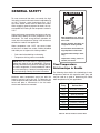
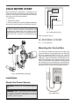
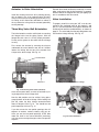
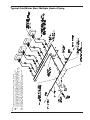
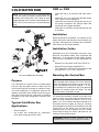
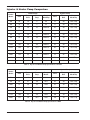
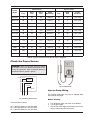
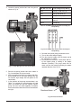
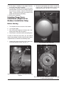
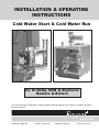
INSTALLATION & OPERATING
INSTRUCTIONS
Cold Water Start & Cold Water Run
For Hi Delta, MVB & Raytherm
Heaters & Boilers
This manual should be maintained in legible condition and kept adjacent to the heater or in another safe place
for future reference.
Catalog No: 1000.57H
Effective: 07-22-10
Replaces: 09-01-09
P/N 241275 Rev. 9
Rev. 9 reflects the following:
Changes to: “Connecting the Valve Assembly” on page 6, Fig. 10 on page 9, Figs 11-13 on page 10, Cold Water Start
Troubleshooting Guide on page 14. Wiring Diagrams on pages 16 & 17, Cold Water Run piping on page 26, Piping Diagram
for Heating Applications on page 29, CWR parts list on page 39
Additions: Note and Fig. 1 on page 6, Caution on page 7, “Mounting Brackets” on page 11 through “Actuator” on page 13,
“Actuator to Valve Orientation” on page 19 through “Connecting the Actuator” on page 20, Piping Diagram for Pool
Applications on page 29, Wiring Diagram on page 33
Deletions: None
2
CONTENTS
WARNINGS
4
GENERAL SAFETY
5
Time/Temperature Relationships in
Scalds
5
COLD WATER START
6
Installation
6
Check Power Source
6
Mounting the Control Box
6
Installing the Temperature Sensor
7
Connecting the Valve Assembly
7
Connecting Power to the Controller
8
Connecting Boiler to Cold Water Start 8
Operation
8
Cold Start Sequence of Operation
9
Troubleshooting
10
Mounting the Actuator to the Valve
11
Mounting Brackets
11
Locating the Rotation Stop
11
Drive Linkage
12
Verifying Ball Position
12
Actuator to Valve Orientation
12
Installing the Three-Way Valve
13
High Pressure Tab
13
Actuator
13
Cold Water Start Troubleshooting
Guide
14
Typical Cold Water Start Piping
15
Wiring Diagram
16
Heater Interface Wiring
17
CWS—MULTIPLE BOILER
18
Materials Included
18
Installation
18
Mounting the Control Boxes
18
Installing the Temperature Sensor
18
Installing the Three-Way Valve
18
Connecting Power to the Controller
18
Connecting Cold Water Start to MultiHeater Interlock Box
18
Connecting Heater to Cold Water Start
Multi-Heater Interlock
18
Actuator to Valve Orientation
19
Three-Way Valve Ball Orientation
19
Valve Installation
19
4 Inch Valve Orientation
20
Connecting the Actuator
20
Typical Cold Water Start Multiple Boiler
Piping
21
Wiring Diagram
22
COLD WATER RUN
23
Purpose
23
Typical Cold Water Run Applications 23
CWR vs. CWS
23
Installation
23
Installation Codes
23
Mounting the Control Box
23
Injector & Heater Pump Comparison 24
Check the Power Source
25
Injector Pump Wiring
25
Injection Pump Cover Installation
27
Typical Cold Water Run Piping Heating Applications
29
Typical Cold Water Run Piping Pool Applications
29
Operation
30
Cold Run Sequence of Operation
30
Cold Water Run Troubleshooting
Guide
31
Wiring Diagrams
32
ILLUSTRATED PARTS LISTS
34
Cold Water Start/Multiple Boiler
34
Cold Water Run
38
3
WARNINGS
Pay Attention to These Terms
DANGER:
Indicates the presence of immediate hazards which will cause severe personal injury, death or substantial property damage if ignored.
WARNING:
Indicates the presence of hazards or unsafe practices which could cause
severe personal injury, death or substantial property damage if ignored.
CAUTION:
Indicates the presence of hazards or unsafe practices which could cause
minor personal injury or product or property damage if ignored.
NOTE:
Indicates special instructions on installation, operation, or maintenance which
are important but not related to personal injury hazards.
NOTE: Minimum 18 AWG, 105°C, stranded wire
must be used for all low voltage (less than 30 volts)
external connections to the unit. Solid conductors
should not be used because they can cause excessive tension on contact points. Install conduit as
appropriate. All high voltage wires must be the same
size (105°C, stranded wire) as the ones on the unit
or larger.
NOTE: Piping diagrams in this manual are not
intended to replace an engineered piping system.
NOTE: Consult the factory for units with a 30 pound
pressure relief valve (PRV).
4
GENERAL SAFETY
To meet commercial hot water use needs, the high
limit safety control on this water heater is adjustable up
to 210°F. However, water temperatures over 125°F
can cause instant severe burns or death from scalds.
When supplying general purpose hot water, the recommended initial setting for the temperature control is
125°F.
Safety and energy conservation are factors to be considered when setting the water temperature on the
thermostat. The most energy-efficient operation will
result when the temperature setting is the lowest that
satisfies the needs of the application.
Water temperature over 125°F can
cause instant severe burns or death
from scalds.
Children, disabled, and elderly are
at highest risk of being scalded.
Water temperature over 125°F can cause instant
severe burns or death from scalds. Children, disabled
and elderly are at highest risk of being scalded.
•
•
See instruction manual before setting temperature at water heater.
Feel water before bathing or showering.
Temperature limiting valves are available.
Feel water before bathing or showering.
Temperature limiting valves are
available, see manual.
NOTE: When this water heater is supplying general
purpose hot water for use by individuals, a thermostatically controlled mixing valve for reducing point of
use water temperature is recommended to reduce
the risk of scald injury. Contact a licensed plumber or
the local plumbing authority for further information.
Time/Temperature
Relationships in Scalds
The following chart details the relationship of water
temperature and time with regard to scald injury and
may be used as a guide in determining the safest
water temperature for your applications.
Maximum water temperatures occur just after the
heater’s burner(s) have shut off. To determine the
water temperature being delivered, turn on a hot water
faucet and place a thermometer in the hot water
stream and read the thermometer.
Water
Temp.
Time to Produce
Serious Burn
120°F
More than 5 minutes
125°F
1-1/2 to 2 minutes
130°F
About 30 seconds
135°F
About 10 seconds
140°F
Less than 5 seconds
145°F
Less than 3 seconds
150°F
About 1-1/2 seconds
155°F
About 1 second
Table courtesy of The Shriners Burn Institute
Table A: Time to Produce Serious Burn
5
COLD WATER START
BLACK
Before beginning the installation, it's important to first
inspect the system and determine what materials you
will need. Some parts are included with the controller
while others you will need to provide.
1 Control Box
1 Temperature Sensor
1 Valve assembly with actuator (Shipped separately)
Wiring and mounting hardware (Provided by installer)
CIRCUIT
BREAKER
WHITE
GREEN
GROUND
NOTE: After testing at the factory it may be prudent
to ship the piping assembly disassembled and
attached to the heater pallet. This is done to avoid
shipping damage and it must be reassembled on the
jobsite. Use Fig. 1 to assist in reassembling the piping.
A B
C
Fig. 2: Wiring Connections
Check the power source:
AC = 108 VAC Minimum, 132 VAC MAX
AB = 108 VAC Minimum, 132 VAC MAX
BC = <1 VAC Maximum
Mounting the Control Box
The control box should be mounted on the side of the
heater to which the system piping and valve assembly
are to be attached as shown in Figs. 4–8. The controller should be mounted so as to provide maximum
support by using the mounting holes provided on the
base of the controller to the side center brace on the
heater. On MVB and Hi Delta models, locating dimples
are provided for ease of drilling the mounting holes.
You will need to drill mounting holes through the heater
side panel for the routing of wiring and the sensor.
Fig. 1: Cold Water Start Assembly
Installation
Check the Power Source
CAUTION: Do not use for swimming pool applications
WARNING: Using a multi-meter, check the following voltages at the breaker panel prior to connecting
any equipment. Make sure proper polarity is followed
and house ground is proven.
Fig. 3: Multi-meter
6
Installing the Temperature
Sensor
NOTE: Four knockouts are located on the bottom
of the control for ease of installation.
Avoid routing wiring on or near other electrical wires,
conduit, motors, spark igniters or other sources of high
intermittent voltage or current. The sensor should be
placed in the dry well on the inlet header, or as indicated in the piping for multiple heaters, as shown on page
21. Ensure it is installed using thermal paste (field
supplied) and that it is held firmly at the bottom of the
well.
11-1/8”
11/16”
Connecting the Valve
Assembly
Connect the valve assembly into the bypass piping.
The branch (port B) is connected to the crossover pipe
(bypass between inlet and outlet). The actuator tail
stock should be oriented to point down. Refer to the
Actuator to Valve Orientation section.
Route wiring from the valve to the controller thru one
of the bottom panel conduit knockouts to TB2. Refer to
the wiring diagram provided on the inside of the controller cover assembly.
7-1/4”
CAUTION: Miswiring the actuator may cause
unwarrantable damage. Verify the wire colors
against the actuator make and model.
Fig. 5: Component Locations—Raytherm Models
514–824
11-1/8”
THREE-WAY VALVE
1”
LEFT SIDE
Models
X
Y
Z
302B-902B
7″
2″
1-9/16″
992B-2342B
13-1/4″
1-5/16″
6-5/8″
Fig. 4: Component Locations—Hi Delta
10-5/16”
Fig. 6: Component Locations—Raytherm Models
926–1826
7
22”
7-5/8”
Reset Switch*
*The reset switch may be located on the front control panel on some
MVB models.
1-1/2”
Fig. 9: Location of TB1 in Control Box
Connecting Power to the
Controller
Fig. 7: Component Locations—Raytherm Models
2100–4001
Connect power from the 120 VAC power input of the
heater to the controller power inputs Terminal Block
(TB1). This is accomplished by connecting wiring from
the control box to the heater 120 VAC power input connections. Refer to the heater wiring diagrams.
9-9/16”
Connecting Boiler to Cold Water
Start
5/16”
1-3/4”
INSTALL
INSULATION ON
INSIDE OF REAR
PANEL
The installer must provide five 18AWG stranded wires
between the heater and the controller terminal block.
Wiring is to be run in separate conduit from line voltage to ensure proper operation. Refer to the diagrams
on page 17 for connection points depending on the
Raypak product being used.
Operation
Verify the following upon a CALL FOR HEAT signal
from the heater:
1. CALL FOR HEAT: LED on PCB illuminates
GREEN.
Fig. 8: Component Locations—MVB
2. START UP MODE: LED on PCB illuminates YELLOW. It should go out in less than 7 minutes, as the
boiler inlet temperature approaches the setpoint
temperature.
CAUTION: Install the foil-faced insulation on the
inside of the rear panel of MVB heaters as indicated
in Fig. 8. Use spray adhesive or high temp foil tape
to attach the insulation. Ensure that the foil faces the
heat exchanger assembly. Failure to install this insulation as directed can cause overheating of the components and may void the warranty on the control.
8
3. The “ACTUATOR” should be in the fully open position or move to the fully open position if not already
there. (Actuator and ball rotated to the at-rest CCW
position).
5. 120VAC-12VDC converter outputs 12VDC to the
common terminal of the reset switch, located on
the bottom of the cold start control panel.
CALL FOR HEAT
START UP MODE
INLET TEMP ERROR
SENSOR OUT OF RANGE
6. The 12VDC signal crosses over the reset switch
and goes to Terminal FS on the cold start circuit
board.
7. Cold start control is now in standby until a Call for
Heat occurs at heater.
8. The heater outputs 24VAC to terminal 4 of terminal block 3 located in Cold Start controller to
indicate a CFH from the heater.
Setpoint
Pot
9. Terminal 4 of TB 3 sends 24VAC to the coil of the
SPST relay located in the cold start control panel.
10. The SPST relay coil is energized and closes the
contacts allowing 24VAC to energize the CFH terminal on the cold start circuit board.
a) A two second delay occurs from the CFH signal to the output of power from terminal MC of
the cold start circuit board.
Fig. 10: Control PCB
4. If the control is operating properly, the “START UP
MODE” LED should go out in less than 7 minutes.
At this point, the inlet water temperature should be
stable at a temperature between 105°F and 120°F
corresponding to the Setpoint Pot setting on the
PCB. The actuator should have stopped moving.
11. 24 VAC is sent from terminal 2 of terminal block 3
to the NO contacts of the DPST relay located in
the cold start control panel.
12. After the two second delay on the cold start circuit
board, pin MC outputs a 24 VAC signal to the coil
of the DPST relay located in the cold start control
panel.
NOTE: The minimum inlet water temperature to the
heater to prevent condensate is 105°F on heaters
with an efficiency of 85% or less, and 120°F on 87%
efficiency heaters. Ensure that during operation the
Setpoint Pot is adjusted properly.
13. The DPST relay coil energizes and closes the NO
contacts.
14. Once the NO contacts of the DPST close, the
heater 24 VAC is sent back to the heater to complete the circuit (pin 3 of terminal block 3) and the
interlock circuit (pin 1 & 2 of terminal block 3)
allowing the heater to fire.
NOTE: If a “DIP” switch is provided on the control
PCB, verify that the switch settings are: 1 = OFF, 2 =
ON, 3 = OFF.
15. Pin FR on the TVC board outputs 10VDC to the
modulating three-way valve actuator to drive it
fully open for two minutes waiting for the heater to
reach full fire.
Cold Start Sequence of
Operation
1. 120VAC to heater sends 120VAC to Cold Start
control on terminal block 1.
16. After the two-minute delay the 10VDC output signal from pin FR reduces to approximately 8VDC.
2. 120/24VAC transformer and 120VAC-12VDC converter are powered.
17. The output signal continues to vary depending on
the heater inlet temperature.
3. 120/24VAC transformer outputs 24VAC to pin 2 of
terminal block 2
NOTE: The heater will lockout and shut down if the
setpoint on the inlet temperature is not achieved
within seven minutes from a call for heat.
4. 24VAC leaves pin 2 of terminal block 2 and goes
to the modulating three-way valve on the 2030VAC lead, and to the NO contacts of the SPST
relay located in the cold start control panel.
9
The DIP switches on the three-way valve actuator
must be set as indicated in the Fig. 11 below:
MODE SELECTION SWITCH
DIP SWITCH SETTINGS
FOR 3-WAY ACTUATOR
VDC
mA
0-10
2-10
DA
RA
FIXED
AUTO
~
6-9
DIRECT ACTING, ON INCREASING SIGNAL
NOTE:
SIDE “B” MUST
FACE AWAY
FROM VALVE
SWITCH MUST BE IN THIS POSITION
TURN CLOCKWISE TO FURTHEST STOP
SIDE
“B”
Fig. 11: Set Dip Switch Settings — Delta Actuator
Fig. 14: Elodrive Actuator — Actuator Shown in Full
System Flow Position
NOTE: The Elodrive actuator is NEMA 4 rated. No
outdoor cover is required.
Troubleshooting
SIDE
“A”
Check your power source using a Volt-Ohm meter;
check the following voltages at TB1 terminal block:
NOTE:
SIDE “A” MUST
FACE AWAY
FROM VALVE
TB1-1 to TB1-2 = 108 VAC Minimum, 132 VAC
Maximum
Fig. 12: Delta Actuator — Actuator Shown in Full
System Flow Position
TB1-1 to TB1-3 = 108 VAC Minimum, 132 VAC
Maximum
TB1-2 to TB1-3 = Must be less than .6 VAC
CAUTION: Delta actuator requires the use of the
factory-supplied weatherproof cover for outdoor
installations.
IF CALL FOR HEAT LED does not illuminate when the
heater has a CFH signal, check for 24VAC between
pins 4 and 5 of TB3 on the cold start control. If voltage
is present, check wiring using the wiring diagram. If
voltage is not present, the problem exists in the heater.
IF VALVE DOES NOT MOVE: Check for voltage out at
TB2-1: Should be a 1VDC to 10VDC output to the
actuator valve. If no voltage is present, check for voltage at pin FS on the control board, there should be a
12VDC signal. If the 12VDC signal is not present, verify that the converter is wired correctly using the wiring
diagram.
DETENT MUST BE
SET TO POSITION 4
IF INLET TEMP ERROR is illuminated: The setpoint
temperature has not been reached within the 7 minute
time period.
• Push the Reset Switch (see Fig. 9) or remove
power and watch for proper operation.
Fig. 13: Elodrive Actuator — Rotation Knob Setting
Set adjustment knob to Position 4
10
•
Mounting Brackets (Elodrive)
Check pump sizing and valve/piping sizing and correct as necessary.
There are different actuator mounting brackets on the
three-way valves. When ordering a replacement
bracket you will receive the newest design available
from the manufacturer. If it appears to be different than
the damaged bracket, the new and old are interchangeable and will fit all valve bodies. See Fig. 16.
IF SENSOR OUT OF RANGE LED is illuminated: The
sensor may have a short or open circuit.
• Press and release the Reset Switch (see Fig. 9)
and watch for proper operation.
• Replace sensor.
• Check wiring using wiring diagram.
Mounting the Actuator to the
Valve
When mounting the actuator to the valve, ensure that
the valve stem is oriented with the machined flat notch
positioned parallel to the “A” and “AB” ports as shown
in Fig. 15.
All actuators used by Raypak include the “spring
return” safety feature. This means that upon loss of
power during operation the valve automatically rotates
back to the full system flow position avoiding high limit
lockouts or other issues.
Fig. 16: Elodrive Mounting Bracket
Locating the Rotation Stop
(Elodrive)
A
An internal rotation stop device is built into the actuator mounting bracket and this can be installed only two
ways for proper operation of the valve. The stop is
labeled on each side with either “D” or “P”. This indicates that the valve is set up for either a diverting
application or proportional (mixing) application.
Raypak uses the three-way valve in a mixing application therefore the “P” designator must be facing away
from the bracket.
B
AB
Flow
The valve rotates in a clockwise direction when it is
operating. The rotational stop must be positioned so
that the drive linkage can rotate. The drive linkage is
keyed to allow only 90 degrees of rotation. Ensure that
the key is positioned so the linkage may rotate clockwise as shown in Fig. 17.
Flat Notch
Fig. 15: Orient Notch Parallel with “A” and “AB” Ports
11
•
•
If you do not see two openings at this point, continue rotating the stem and ball until you do.
Once you can see two openings, STOP, as shown
in Fig. 18. Then rotate the stem counterclockwise
until only one opening remains e.g. you can see
completely through the valve (through ports A and
AB).
Now the ball is correctly oriented inside of the valve
body. Reassemble the valve, base and actuator, and
then install the assembly into your piping system as
indicated in this manual.
POSITION ROTATIONAL
STOP SO THAT DRIVE
LINKAGE CAN ROTATE
PORT AB
Fig. 17: Elodrive Rotational Stop Positioning
Drive Linkage (Elodrive)
Fig. 18: Verifying Ball Position
Actuator to Valve Orientation
The drive linkage for the 2” NPT and 2-1/2” NPT threeway valves originally were supplied with an orientation
groove in the end of the stem. This groove has now
been removed by the vendor. All new linkage stems
will have a smooth end. Using the groove to determine
ball position inside of the valve is not reliable and
should be avoided.
Install the actuator so that the tail is pointing downward
as shown in Fig. 19. You may also install it horizontally, however, DO NOT mount it so that the tail is
pointing up as shown in Fig. 20. Doing so will allow
water and debris to collect in the cup where the wiring
exits the actuator, potentially causing damage.
Verifying Ball Position
All field-installed valves must have the ball properly
positioned. Occasionally differences occur from the
manufacturer of the valve body. The square stem that
the drive linkage attaches to should have a machined
notch to verify ball position, however on occasion it is
not there. To properly orient the ball follow these
instructions PRIOR to installation into your plumbing
system.
•
•
Remove the actuator and base from the valve
body.
With port “AB” facing you, rotate the valve stem
approximately 45 degrees clockwise. You must
see two port openings if the ball is correctly oriented.
Fig. 19: Recommended Orientation of Actuator
12
HIGH
PRESSURE
TAB
Fig. 21: High Pressure Tab
Actuator
The ELODRIVE actuator has a manual override for the
valve. The label located over the silver colored primary
label states, “Please read manual before using manual override”. Using the Allen wrench supplied with the
loose valve, place it in the hexagonal opening under
the label. See Fig. 22.
Fig. 20: Incorrect Orientation of Actuator
Installing the Three-Way Valve
When threading any pipe into the ports of the threeway valve, a backing wrench MUST be employed. You
must capture the valve body with a secondary wrench
to avoid damaging the internal seals. Valve bodies
leaking from improper installation are non-warrantable.
By pressing the red release button on the tail of the
actuator and simultaneously rotating the Allen wrench
you can rotate the ball clockwise. Once you release or
remove the Allen wrench the ball will return to its original position by way of the “spring return”. This is an
easy way to determine if the ball is oriented properly
inside of the valve.
High Pressure Tab
Located between the valve body and the actuator
mounting bracket, is a yellow tab labeled “High
Pressure” see Fig. 21. This is for maintenance of the
valve only.
If the valve stem begins leaking beneath the yellow tab
the internal packing material must be replaced. The
“High Pressure” tab is held on with two screws located
under the mounting bracket.
INSERT ALLEN
WRENCH UNDER
THIS LABEL
To replace the packing material, all water pressure
must be removed from the valve assembly and the
assembly must be isolated from the system water.
Then remove the actuator and bracket, then remove
the two screws holding the “High Pressure” tab in
place.
At this point the packing material can be removed and
replaced just like any other valve assembly. The packing material is not available from Raypak.
Fig. 22: Actuator
13
Cold Water Start Troubleshooting Guide
Step 1
Does TB1 of cold start
controller have 120
VAC?
Verify 120VAC at separate
circuit breaker and correct.
NO
Is there a Call For
Heat at the heater?
YES
YES
Step 2
Heater is in standby mode
NO
Are the 120/24VAC
transformer and 120VAC12VDC inverter in the cold
start controller powered?
Correct wiring to
match wiring diagram
NO
YES
Replace 120VAC-12VDC
inverter or correct wiring.
Step 3
Does the cold start 12VDC inverter
output 12VDC to the reset switch
and to common pin FS of the cold
start circuit board?
NO
NO
Does the reset switch send
12VDC to terminal FS on the
cold start circuit board?
YES
YES
Step 4
Does the cold start 120/24VAC
transformer output 24VAC to pin
2 of TB2 and the valve actuator?
YES
Replace transformer or
correct the wiring
NO
Is 24VAC present at CFH
terminal on cold start circuit
board?
Step 5
Check and verify 24VAC between pin 4 and 5
of TB3 in cold start controller and correct.
NO
YES
Step 6
Does cold start DPDT
relay coil receive 24VAC
from MC on circuit board?
Call our Technical Service Department
1-805-278-5300
Replace circuit board
NO
YES
YES
YES
Is sensor resistance correct?
Step 7
Are the terminals 1-4 of TB3
connected to N.O. contacts of
DPDT relay?
NO
NO
YES
Step 8
Correct wiring
Correct settings or valve
orientation
Replace sensor
Are terminals 1-4 of TB3
correctly connected back
to the heater?
NO
Correct wiring
NO
YES
YES
Is the actuator modulating after
2-1/2 minutes?
YES
Is the heater tripping the high
limit?
Verify actuator is set to reverse acting
and three-way valve is not installed
backwards.
YES
Step 9
2” & 2-1/2” valve must
rotate CW on decreasing 010VDC signal. 4” valve will
rotate CCW.
NO
NO
The unit is okay
NO
Step 10
Is 0-10VDC present at
connection FR of cold start
circuit board?
YES
NO
Replace cold start circuit board
NO
Does cold start circuit board lock-out on
“Sensor out of Range”?
14
YES
Is system water
temperature
below 32ºF?
NOTES:
1. LOCATE UNIONS TO FACILITATE SERVICING OF PLUMBING SIDE.
2. PLUMB SWING CHECK VALVE IN GRAVITY-CLOSED POSITION.
3. PIPE ALL RELIEF VALVES TO DRAIN, OR AS LOCAL CODES REQUIRE.
4. BUFFER TANK REQUIRED WHEN WATER VOLUME IN BOILER LOOP
IS NOT ADEQUATE TO PROVIDE STABLE TEMPERATURE CONTROL.
CONSULT FACTORY FOR TANK SIZING.
5. SYSTEM FLOW MUST EXCEED HEATER FLOW AT ALL TIMES.
Typical Cold Water Start Piping
15
Wiring Diagrams—Cold Water Start
BRACKET RESTS AGAINST
VALVE MOUNTING CHASIS
* VALVE NOT DEPICTED
Panel Control and Wrapper Control Cover Assembly
with Support Valve Cover; Full Assembly
16
HEATER INTERFACE WIRING FOR CWS OR CWR
CWS/CWR
CONTROL OR
MULTIPLE BOILER
INTERFACE
CWS/CWR
CONTROL OR
MULTIPLE BOILER
INTERFACE
CWS/CWR
CONTROL OR
MULTIPLE BOILER
INTERFACE
17
COLD WATER START—
MULTIPLE HEATER
Installing the Three-way Valve
Install three-way diverting valve into common boiler
piping manifold as shown in the diagram on page 18.
Boiler common outlets to be connected at port AB.
Discharge to system from port A with bypass port
being port B. Common pipe sizing may be larger than
three-way valve port connections requiring the use of
increasers for installation (see Table B for valve sizing). It is recommended that three-way valve be
installed as near the main system piping as is feasible.
Route control wiring in separate conduit to the Cold
Water Start control box and wire as shown in the diagram on page 19.
(Maximum 4 heaters)
Materials Included
1
1
1
1
Cold Start Control Box
Multi-Boiler Interlock Box
Water Sensor & Well
Three-way Diverting Valve assembly with Actuator
NOTE: Flanges, bolts and gaskets for flanged
valves supplied by others.
Connecting Power to the Controller
Installer to provide a dedicated 120V circuit with local
disconnect to the Cold Water Start Control. Refer to
wiring Fig. 9 on page 8 for detailed instruction.
Installation
Mounting the Control Boxes
Connecting Cold Water Start to
Multi-Heater Interlock Box
Cold Start Control and Multi-Boiler Interlock should be
mounted in such a manner as to allow for easy access
for wiring of the boiler interlock connections.
Installer to provide four 18AWG stranded wires
between pins 7-10 on the Cold Start Control and 7-10
on the Multi-Boiler Interlock as shown in the diagram
on page 22. Do not use solid core wire when wiring
any portion of the Cold Start Multi-Boiler system.
Installing the Temperature Sensor
Temperature sensor to be installed in a drywell with
thermal paste at the location indicated in the diagram
on page 21 to ensure proper operation of the control
system. Installer must ensure the drywell extends at
least 2 inches into the water flow path. Sensor wiring
must be run in separate conduit from line voltage and
should be a minimum of 18 AWG shielded cable. Refer
to diagram on page 22 for wiring information.
Connecting Heater to Cold Water
Start Multi-Heater Interlock
Installer to provide five 18AWG stranded wires
between each boiler and Multi-Boiler Interlock box.
Wiring to be run in separate conduit from line voltage
to ensure proper operation. Refer to the diagram on
page 22 for connection points depending on Raypak
product being used.
Total Load
(MBTU)
Valve
Size
Minimum
Pipe Size
Cv
Flow
Rate
(gpm)
Valve
Pressure
Drop
∆T @
Max Size
∆T @
Min. Size
Order
No.
600-1000
2” NPT
2
57
70
3.5 ft
22
14.4
012228
150
5.2 ft
29.1
20.1
012230
1001-1800
2.5” NPT
2.5
2601-4000
6001-8000
1801-2600
4001-6000
3
74
100
100
4” FLG*
4
152
4” FLG*
6
327
2.5” NPT
4” FLG*
4
254
4.2 ft
30.2
220
4.8 ft
30.5
22.9
012231
440
4.2 ft
30.5
22.5
012233
330
3.9 ft
Standard boiler pump options offered by Raypak may NOT be appropriate for these applications.
*CAUTION: Approved for closed loop systems only.
Table B: Valve Sizing Chart
18
30.5
16.8
20.3
012229
012232
Actuator to Valve Orientation
Reinstall the actuator and bracket assembly in reverse
order, and ensure that the ball assembly is properly
oriented. Mount the flanged valve into your piping system in accordance with this manual.
Install the actuator so that the tail is pointing horizontally as shown in Fig. 26 or is pointing down. DO NOT
mount it so that the tail is pointing up as shown in Fig.
20. Doing so will allow water and debris to collect in
the cup where the wiring exits the actuator, potentially
causing damage.
Valve Installation
To properly install this valve port “AB” must be connected to the combined outlet of the heater(s); and
port “B” must be attached to the bypass between the
combined inlet and the combined outlet, as shown on
page 21. The valve body has the port designators cast
into the drive linkage housing. See Fig. 25.
Three-Way Valve Ball Orientation
The ball orientation must be verified prior to mounting
the flanged valve into the piping system. With the
flanged four-inch valve it is a fairly simple procedure.
Do not use the groove on the end of the drive linkage
to verify.
First, remove the actuator by removing the wing-nut
underneath the mount bracket near the tail. Second,
loosen the locking bolt on top of the actuator that
clamps to the drive linkage. See Fig. 23.
LOCKING BOLT
Fig. 24: Rotating the Drive Linkage
WING NUT
Fig. 23: Removing the Actuator (Elodrive)
Once this has been done, remove the actuator by lifting straight off the drive linkage shaft.
Now the ball position must be verified. Using pliers,
grasp the base of the drive linkage. While looking into
port AB, rotate the drive linkage counterclockwise
about 45 degrees. See Fig. 24. You should see two
partial openings similar to Fig. 18.
PORT AB
If you do not see the two partial openings after 45
degrees of rotation, continue rotating until you do.
Once you see the two partial openings, STOP. Now
rotate the shaft in the reverse direction (clockwise)
until you can see straight through to valve from port AB
to port A.
Fig. 25: Valve Orientation
19
4-Inch Valve Orientation
The valve must be installed so that the combined boiler outlets enter through Port "AB" (See Fig. 26). Port
"B" is the bypass port and port "A" is the return to the
system (port designations are cast into the stem of the
valve body). The valve body should be installed so that
the actuator input shaft is in the vertical or horizontal
position. The Actuator stem should never be hanging
downward.
The actuator, as shipped from the factory, is in the horizontal position when the valve is installed as shown in
Fig. 26. The actuator position can be changed to suit
job site conditions.
NOTE: SIDE A MUST
FACE AWAY FROM
VALVE BODY
Under no circumstances should the actuator be positioned such that the electrical connection is pointing
upwards (see Fig. 20) as this can allow for moisture or
debris to enter the actuator assembly and potentially
damage the actuator.
Before installing into the piping system, verify the
valve is positioned properly by referring to Fig. 26 and
the diagram on page 21.
Fig. 27: Elodrive actuator used on 4” valves
(Actuator shown in full system flow position.)
Connecting the Actuator
The actuator for the 4” valves rotates opposite to the
direction of the smaller actuators. On an Elodrive
actuator, Side A must be facing away from the valve.
The 4-inch valve is shipped loose, and must be field
wired. Connect the actuator leads to the Cold Water
Start control panel, as indicated in the wiring diagram
on Page 16.
DETENT MUST BE
SET TO POSITION 2
NOTE: SIDE A
MUST FACE AWAY
FROM 4” VALVE BODY
Fig. 26: Valve Orientation (Elodrive Actuator)
Fig. 28: Rotational Setting for Elodrive Actuator
Used on 4” Valves
20
5.
6.
NOTES:
1.
2.
3.
4.
PLUMB SWING CHECK VALVE IN GRAVITY-CLOSED POSITION.
PIPE ALL RELIEF VALVES TO DRAIN, OR AS LOCAL CODES REQUIRE.
LOCATE UNIONS TO FACILITATE SERVICING OF PLUMBING SIDE.
BUFFER TANKS MAY BE REQUIRED TO PROVIDE STABLE TEMPERATURE
CONTROL ON SYSTEMS WITH VARIABLE FLOW OR LOW WATER VOLUME.
CONSULT FACTORY FOR SELECTION CRITERIA.
MAXIMUM 4 TIMES THE PIPE DIAMETER OR 12”, WHICHEVER IS LESS.
SYSTEM FLOW MUST EXCEED HEATER FLOW AT ALL TIMES.
Typical Cold Water Start Multiple Heater Piping
21
FOR HEATER INTERFACE WIRING
(SEE PAGE 17)
CWS CONTROL
BOX ASSY
(SEE PAGE 16)
Wiring Diagram
Multiple Heater
22
COLD WATER RUN
CWR vs. CWS
•
NOTE: After testing at the factory it may be prudent
to ship the piping assembly disassembled and
attached to the heater pallet. This is done to avoid
shipping damage and it must be reassembled on the
jobsite. Use Fig. 29 to assist you in reassembling the
piping.
•
•
•
Cold water start is for transient cold water operation.
Cold water run is for continuous operation below
105°F system return temperature.
Cold water start maintains design flow rate at system design temperature but reduces boiler flow
rate during heavy bypass operation.
Cold water run maintains constant design flow rate
in the boiler.
Installation
Before beginning the installation, it's important to first
inspect the system and determine what materials you
will need. Some parts are included with the controller
while others you will need to provide.
Installation Codes
Installations must be in accordance with local, state,
provincial, and national codes, laws, regulations and
ordinances. In the absence of local codes, installations must be in accordance with the latest editions of
the:
• National Fuel Gas Code, ANSI Z223.1/NFPA 54
• National Electrical Code, ANSI/NFPA 70
• For Canada only: CAN/CSA B149 Installation Code
and CSA C22.1 C.E.C. Part 1 and Part 2
Mounting the Control Box
Fig. 29: Cold Water Run Assembly
Purpose
NOTE: The heater should not be located in an area
where possible water leakage will result in damage
to the area adjacent to the heater or to the structure.
When such locations cannot be avoided, it is recommended that a suitable drain pan, with adequate
drainage, be installed under the heater. The pan
must not restrict combustion air flow.
The Cold Water Run system utilizes a variable-speed
pump to inject the proper amount of water from the
main system loop into the heater to maintain the optimum inlet temperature. This approach allows the full
capacity of the heater to be utilized to meet the system
load, while at the same time continuously maintaining
the optimum inlet water temperature to prevent condensation.
The control box should be mounted on the side of the
heater to which the system piping and pump assemblies are to be attached as shown in Figs. 4–8 on
pages 7 & 8. The controller should be mounted so as
to provide maximum support by using the mounting
holes provided on the base of the controller to the side
center brace on the heater. You will need to drill
mounting holes for #10 hardware and 3/4” conduit
access holes through the heater side panel for the
routing of wiring and the sensor.
Typical Cold Water Run
Applications
•
•
Swimming pools.
Any system with steady-state (or “consistent”)
return water temperature below 105°F.
CAUTION: Remote mounted controller must be
installed within 25 feet of wire length to the heater.
23
Injector & Heater Pump Comparison
Heater Pump
Injector Pump
Heater
Model
Flow
Temp.
Rise
Press.
Drop
Pump
Model/Imp.
Flow
Temp.
Rise
Pump
Model-hp
302
32
16
2
112
13
40
1911-1⁄4 hp
402
34
20
2
112
17
40
1911-1⁄4 hp
502
42
20
2.3
1630/4.0
22
40
1911-1⁄4 hp
652
55
20
4.1
1630/4.0
28
40
1911-1⁄4 hp
752
63
20
5.7
1630/4.2
32
40
1911-1⁄4 hp
902
76
20
8.4
1630/4.2
38
40
1911-1⁄4 hp
992
83
20
5.2
1630/4.7
42
40
1911-1⁄4 hp
1262
107
20
9.6
1630/4.7
54
40
1911-1⁄3hp
1532
120
22
12.4
1632/5.6
62
42
1911-1⁄3hp
1802
120
25
13
1632/5.6
68
45
1911-1⁄3hp
2002
132
26
19
1634/6.1
74
46
1935-3⁄4hp
2072
132
27
19
1634/6.1
75
47
1935-3⁄4hp
2342
132
30
21.4
1634/6.1
80
50
1935-3⁄4hp
Table C: Injector and Heater Pump Specifications—Hi Delta
Heater Pump
Injector Pump
Heater
Model
Flow
Temp.
Rise
Press.
Drop
Pump
Model
Flow
Temp.
Rise
Pump
Model-hp
503
58
15
2.4
1611
29
30
1911-1⁄4 hp
753
63
21
5.6
1611
44
30
1911-1⁄4 hp
1003
87
20
8.2
1630
58
30
1911-1⁄3 hp
1253
86
25
12.2
1630
73
30
1911-1⁄3 hp
1503
100
26
18.5
1632
87
30
1911-1⁄3 hp
1753
109
28
26
1634
102
30
1911-1⁄3 hp
2003
116
30
36.2
1636
116
30
1935-3⁄4 hp
Table D: Injector and Heater Pump Specifications—MVB
24
Heater Pump
Injector Pump
Heater
Model
Flow
Temp.
Rise
Press.
Drop
Pump
Model/Imp.
Flow
Temp.
Rise
Pump
Model-hp
926/962
79
20
8.5
1630/4.7
50
32
1911-1⁄4 hp
1083/1125
90
21
12.0
1630/4.7
50
37
1911-1⁄4 hp
1178/1223
90
22
12.5
1630/4.7
60
33
1911-1⁄3 hp
1287/1336
90
25
13.2
1630/4.7
60
37
1911-1⁄3 hp
1414/1468
90
27
14.0
1632/5.65
60
40
1911-1⁄3 hp
1571/1631
90
30
14.5
1632/5.65
60
45
1911-1⁄3 hp
1758/1826
90
34
15.4
1632/5.65
60
50
1911-1⁄3 hp
2100
172
20
11.0
1641/6.9
130
26
1935-3⁄4hp
2500
200
21
15.8
1641/6.9
130
32
1935-3⁄4hp
3001
200
25
16.7
1641/6.9
130
38
1935-3⁄4hp
3500
200
29
17.5
1641/6.9
130
44
1935-3⁄4hp
4001
200
33
18.7
1641/6.9
130
50
1935-3⁄4hp
Table E: Injector and Heater Pump Specifications—Raytherm
Check the Power Source
WARNING: Using a multi-meter, check the following voltages at the circuit breaker panel prior to connecting any equipment. Make sure proper polarity is
followed and house ground is proven.
HOT (L1)
BLACK
CIRCUIT
BREAKER
HOT (L2) WHITE
Fig. 31: Multi-meter
GREEN
GROUND
A B
Injector Pump Wiring
The 3-phase cold water run pump is shipped loose
and must be field wired.
C
Fig. 30: Wiring Connections
Before Starting
Check the power source:
1. Turn off power to the unit at the circuit breaker.
2. Turn off gas supply.
3. Shut off the water supply to the heater and, if necessary, drain water from the system.
AC = 104 VAC Minimum, 126 VAC MAX
AB = 208 VAC Minimum, 252 VAC MAX
BC = 104 VAC Minimum, 126 VAC MAX
25
4. Locate the pump junction box and wiring decal
shown in Fig. 32.
230 VAC 3 ø Line
Low Voltage Pump Wiring
Black
Orange (3) and Gray (9)
White
Pink (7) and Blue (1)
Red
Red (8) and White (2)
———————
Green
Yellow (4) and Black (5) and
Violet (6)
Ground Lug
Table F: Cold Water Run Control Panel and Injector
Pump Wiring
Fig. 33: Cold Water Run Control Panel and Injector
Pump Wiring
8. Re-install the injector pump junction box cover.
9. Turn on the water and gas supply.
10. Turn the electrical supply on to the heater and to
the cold water run system.
11. Turn heater on to receive a “call-for-heat” and verify the injector pump is rotating in the proper
direction (clockwise). The pump volute has an
arrow cast into the housing indicating the proper
rotational direction. See Fig. 34.
Cover
Fig. 32: Pump Wiring Decal and Junction Box
5. Remove the pump junction box cover shown in
Fig. 32 and locate the 9 wires inside.
6. Wire in accordance with the low voltage (230 VAC)
decal located next to the pump junction box (do
not connect high voltage 460 volt power to the
control box).
7. In the absence of the pump mounted decal, use
Table F to complete the wiring between the cold
water run control box and the 3-phase injector
pump. Use wire nuts (field supplied) to complete
these connections and ensure that all connections
are tight.
Directional Arrow
Fig. 34: Directional Arrow
26
12. If the pump is rotating in the proper direction,
secure the heater from installation.
13. If the pump is rotating incorrectly, turn off power
and swap ONLY two of the line voltage leads into
the pump (for example, swap the red and black
leads). Confirm that the pump now rotates in the
proper direction before proceeding.
14. Secure from installation.
2. Remove the pump body then rotate it so that the
electrical box is pointing downward, ensuring not
to damage the seal. See Figs. 36, 37 and 38.
Injection Pump Cover
Installation (Required for
Outdoor Installation Only)
Before Starting
1. Turn off power to the unit at the circuit breaker.
2. Turn off gas supply.
3. Shut off the water supply to the heater and, if necessary, drain water from the system.
4. Allow heater to cool down before attempting work.
In order to install the pump cover, you will need to
rotate the pump body so that the electrical box is pointing downward, as outlined in the following steps:
1. Loosen and remove the eight (8) 9/16” bolts holding the pump body in place. See Fig. 35.
Fig. 36: Remove the pump body
Fig. 35: Remove the eight bolts holding the pump body
in place
27
Fig. 37: Be sure not to damage the seal when removing
or replacing the pump body
Fig. 40: Pump cover - angle view
Fig. 38: Reposition the pump body so that the electrical
box points downward
3. Insert and tighten all eight (8) bolts, securing the
pump body in place.
4. You will now be able to install the pump cover. See
Figs. 39 and 40.
Fig. 39: Place the cover on the pump
28
Typical Cold Water Run Piping - Heating Applications
ALTERNATE SENSOR POSITION
NOTES:
1.
2.
3.
4.
LOCATE UNIONS TO FACILITATE SERVICING OF PLUMBING SIDE.
PLUMB SWING CHECK VALVE IN GRAVITY-CLOSED POSITION.
PIPE ALL RELIEF VALVES TO DRAIN, OR AS LOCAL CODES REQUIRE.
SYSTEM FLOW MUST EXCEED HEATER FLOW AT ALL TIMES.
12” MAX, OR MIN FEASIBLE
Typical Cold Water Run Piping - Pool Applications
NOTES:
1.
2.
3.
4.
5.
SEE NOTE 4
29
LOCATE UNIONS TO FACILITATE SERVICING OF PLUMBING SIDE.
PLUMB SWING CHECK VALVE IN GRAVITY-CLOSED POSITION.
PIPE ALL RELIEF VALVES TO DRAIN, OR AS LOCAL CODES REQUIRE.
USE REDUCING TEES WHERE INDICATED.
SYSTEM FLOW MUST EXCEED HEATER FLOW AT ALL TIMES.
Operation
•
•
•
•
7. After the two second delay on the cold run circuit
board, pin MC outputs a 24 VAC signal to terminal
AL0 of the Hitachi inverter.
8. The AL0 relay closes and outputs a 24 VAC signal
to the coil of the DPST relay located in the cold run
control panel.
9. The DPST relay coil energizes and closes the NO
contacts.
10. Once the NO contacts of the DPST close, the
heater 24 VAC is sent back to the heater to complete the circuit (pin 3 of terminal block 3) and the
interlock circuit (pin 1 & 2 of terminal block 3)
allowing the heater to fire.
11. Pin SC of the cold run circuit board sends 10VDC
to Pin 1 (Forward) on Hitachi Inverter.
12. PCS terminal on Inverter outputs 12VDC signal to
the common terminal of the reset switch located
on the bottom of the cold run control panel.
13. The 12VDC signal crosses over the reset switch
and goes to Pin FS and to pin S1 on cold run circuit board.
14. Pin FR on the TVC board outputs 10VDC to pin O
of the Inverter to drive injector pump at full speed
for two-minutes waiting for the heater to reach full
fire.
15. After the two-minute delay the 10VDC output signal from pin FR reduces to approximately 8VDC at
the inverter thus slowing the pump to approximately 50 Hz.
16. The output signal continues to vary depending on
the heater inlet temperature.
Run full system flow for two minutes.
Initiate PID pump control to achieve target inlet
temperature by slowing injector pump.
Boiler ∆T will not increase during bypass operation.
If target temperature is not achieved after 7 minutes from “call for heat”, the system will shut down.
Fig. 41: Control Board
The heater will lockout and shut down if the set point
on the inlet temperature is not achieved within 7 minutes from a call for heat.
Cold Run Sequence of
Operation
The DIP switches on the Hitachi Inverter must be set
as indicated on Fig. 42 below.
1. Supply separate 220VAC, 1 phase, 60 Hz power
for the Hitachi Inverter (blue-colored inverter), or
120VAC or 220VAC, 1 phase, 60 Hz power for the
AC Tech Inverter (white-colored inverter).
2. Call for heat occurs at heater.
3. The heater outputs 24VAC to terminal 4 of terminal block 3 located in Cold Run controller.
4. Terminal 4 of TB 3 sends 24VAC to the coil of the
SPST relay located in the cold run control panel.
5. The SPST relay coil is energized and closes the
contacts allowing 24VAC from the Cold Run control transformer to be sent to the CFH terminal of
the Cold Run circuit board.
a) A two second delay occurs from the CFH signal waiting to send power from terminal MC of
the cold run circuit board.
6. 24 VAC is sent from terminal 2 of terminal block 3
to the NO contacts of the DPST relay located in
the cold run control panel.
Fig. 42: DIP Switch Settings (Hitachi)
30
Cold Water Run Troubleshooting Guide
*NOTE:
Step 1
See wiring diagrams
for proper supply voltage based
on inverter used on heater.
Does TB1 of cold run
controller have 120VAC*
or 230VAC*?
Verify 120VAC* or 230VAC*
from separate circuit breaker
NO
Is there a Call For
Heat at the heater?
YES
YES
Step 2
Heater is in standby mode
NO
Is the inverter in the
cold run controller powered?
NO
Correct Wiring
YES
Step 3
Does the cold run inverter output 12VDC from PCS to the
reset switch, Pin S1 and pin FS of the cold run circuit board?
Replace inverter or
correct wiring
NO
YES
Step 4
Is 24VAC present at CFH
connection on cold run circuit
board?
NO
Check and verify 24VAC between pin 4 and 5
of TB3 in cold run controller and correct.
YES
Step 5
Does cold run terminal AL0
relay coil receive 24VAC
from MC on circuit board?
NO
Replace circuit board
Call our Technical Service Department
1-805-278-5300
YES
Step 6
Are the terminals 1-2 of TB3
connected to N.O. contacts of
DPDT relay?
YES
Correct wiring
NO
YES
Is sensor resistance correct?
NO
YES
NO
Replace sensor
Correct 3 phase pump wiring
Step 7
Are terminals 1-4 of TB3 correctly
connected back to the heater?
NO
Correct wiring
NO
YES
YES
Step 8
Step 9
Is the injector pump
modulating after 2-1/2
minutes?
Is the heater tripping the high
limit?
YES
Verify pump is rotating in proper
direction
Pump must decrease
RPM’s on decreasing 010VDC signal
YES
NO
NO
The unit is okay
Is 0-10VDC present at
connection FR of cold run circuit
board and pin 0 of the inverter?
NO
Replace cold run circuit board
or correct wiring.
NO
Step 10
YES
Does cold run circuit board lock-out on
“Sensor out of Range”?
31
YES
Is the system
water temperature
below 0ºF?
17
Wiring Diagram—Cold Water Run (Hitachi Inverter)
32
(SEE PAGE 17)
Wiring Diagram—Cold Water Run (AC Tech Inverter)
33
ILLUSTRATED PARTS LISTS
34
Cold Water Start
Cold Water Start
35
Cold Water Start
Multiple Boiler Interlock
36
CALL OUT
1-C
9-C
2-C
3-C
4-C
5-C
6-C
7-C
8-C
1-H
1-M
7-M
2-M
3-M
4-M
5-M
6-M
1-S
2-S
3-S
4-S
DESCRIPTION
PC BOARD ASSY-CONTROL
RELAY - DPDT 24VDC COIL
TRANSFORMER
POWER SUPPLY 120VAC/12VDC
RELAY - DPDT 24V
RELAY - SPDT 24V
GROUND LUG
TEMP SENSOR 10K (NOT SHOWN)
ALARM RESET SWITCH
INLET ADAPTER 2-1/2 NPT
PUMP-WATER BR 2" FLANGE, 1/4 HP
PUMP-WATER CI 2" FLANGE, 1/4 HP
PUMP-WATER BR 2" FLANGE, 1/2 HP
PUMP-WATER CI 2" FLANGE, 1/2 HP
PUMP-WATER BR 2-1/2" FLANGE, 3/4 HP
PUMP-WATER CI 2-1/2" FLANGE, 3/4 HP
PUMP-WATER BR 2-1/2" FLANGE, 1 HP
PUMP-WATER CI 2-1/2" FLANGE, 1 HP
PUMP-WATER BR 2-1/2" FLANGE, 1.5 HP
PUMP-WATER CI 2-1/2" FLANGE, 1.5 HP
PUMP-WATER BR 2-1/2" FLANGE, 2.0 HP
PUMP-WATER CI 2-1/2" FLANGE, 2.0 HP
PUMP FLANGE GASKET
THREE-WAY VALVE ASSY 2" NPT 24 Cv
THREE-WAY VALVE ASSY 2" NPT 38 Cv
THREE-WAY VALVE ASSY 2" NPT 57 Cv
THREE-WAY VALVE ASSY 2-1/2" NPT 74 Cv
THREE-WAY VALVE ASSY 2-1/2" NPT 100 Cv
THREE-WAY VALVE ASSY 4" NPT 152 Cv
THREE-WAY VALVE ASSY 4" NPT 254 Cv
THREE-WAY VALVE ASSY 4" NPT 327 Cv
ACTUATOR-35 IN LBS (ELODRIVE)
ACTUATOR-53 IN LBS (DELTA CONTROLS)
ACTUATOR-132 IN LBS (ELODRIVE)
ACTUATOR-177 IN LBS (DELTA CONTROLS)
THERMOMETER-VERTICAL
MOUNTING KIT (ELODRIVE)
MOUNTING KIT (DELTA CONTROLS)
MOUNTING KIT 4" VALVE (ELODRIVE)
MOUNTING KIT 4" VALVE (DELTA CONTROLS)
ACTUATOR COVER (DELTA CONTROLS ONLY)
ACTUATOR COVER 4" (DELTA CONTROLS ONLY)
CONTROL BOX SHEET METAL
CONTROL BOX COVER
INTERLOCK BOX SHEET METAL
CONTROL BOX MTG BRACKET
NOTE: Sizing is specific to the application.
37
HI DELTA
011717F
005962F
011718F
011719F
011720F
009039F
007155F
010787F
005641F
N/A
007226F
007232F
N/A
N/A
007348F
007354F
007348F
007354F
N/A
N/A
N/A
N/A
013423F
011939F
011721F
011722F
011723F
011724F
012231
012232
012233
012447F
011834F
012448F
012449F
000919
012450F
012452F
012451F
012453F
012454F
012455F
011716F
N/A
012249F
N/A
M VB
011717F
005962F
011718F
011719F
011720F
009039F
007155F
010787F
005641F
N/A
007226F
007232F
007347F
007353F
007348F
007354F
007348F
007354F
007937F
007938F
N /A
N /A
013423F
011939F
011721F
011722F
011723F
011724F
012231
012232
012233
012447F
011834F
012448F
012449F
N/A
012450F
012452F
012451F
012453F
012454F
012455F
011716F
011978F
012249F
N/A
RAYTHERM
011717F
005962F
011718F
011719F
011720F
009039F
007155F
010787F
005641F
012315F
007226F
007232F
007347F
007353F
007348F
007354F
007348F
007354F
007937F
007938F
012317F
012318F
013423F
011939F
011721F
011722F
011723F
011724F
012231
012232
012233
012447F
011834F
012448F
012449F
000919
012450F
012452F
012451F
012453F
012454F
012455F
011716F
N/ A
012249F
012367F
Cold Water Run
38
CALL OUT
1-C
11-C
HI DELTA
HI DELTA SS
MVB
PC BOARD ASSY-CONTROL
DESCRIPTION
011717F
N/A
011717F
RAYTHERM
011717F
RELAY - DPDT 24VDC
005962F
N/A
005962F
005962F
2-C
RELAY - DPDT 24VAC
011720F
N/A
011720F
011720F
3-C
RELAY - SPDT 24VAC
009039F
N/A
009039F
009039F
4-C
INVERTER
011835F
N/A
011835F
011835F
INVERTER - DUAL VOLTAGE
012984F
N/A
012984F
012984F
013070F
9-C
CHIP - PROGRAMMED
013070F
N/A
013070F
5-C
10-C
TRANSFORMER
011718F
N/A
011718F
011718F
6-C
TEMPERATURE SENSOR 10K (NOT SHOWN)
010787F
N/A
010787F
010787F
005641F
7-C
ALARM RESET SWITCH
005641F
N/A
005641F
8-C
GROUND LUG
007155F
N/A
007155F
007155F
1-H
INLET ADAPTER-2-1/2 NPT (2100-4001)
N/A
N/A
N/A
012316F
1-M
PUMP - WATER BR 1-1/2" FLANGE, 1/8 HP
N/A
013425F
N/A
N/A
PUMP - WATER CI 1-1/2" FLANGE, 1/8 HP
N/A
013426F
N/A
N/A
PUMP - WATER BR 2" FLANGE, 1/4 HP
007226F
007226F
007226F
007226F
PUMP - WATER CI 2" FLANGE, 1/4 HP
007232F
007232F
007232F
007232F
PUMP - WATER BR 2-1/2" FLANGE, 3/4 HP
007348F
N/A
007348F
007348F
PUMP - WATER CI 2-1/2" FLANGE, 3/4 HP
007354F
N/A
007354F
007354F
PUMP - WATER BR 2-1/2" FLANGE, 1 HP
007351F
N/A
007351F
007351F
PUMP - WATER CI 2-1/2" FLANGE, 1 HP
007357F
N/A
007357F
007357F
PUMP FLANGE GASKET (2" & 2-1/2" FLANGES)
013423F
013423F
013423F
013423F
000919
000919
000919
000919
N/A
4-M
2-M
THERMOMETER-VERTICAL
3-M
INJECTOR PUMP, SS 1/8 HP (NOT SHOWN) (HD251)
N/A
951446
N/A
INJECTOR PUMP, CI 1/8 HP (NOT SHOWN) (HD251)
N/A
951447
N/A
N/A
INJECTOR PUMP, BR 1/8 HP (NOT SHOWN)
N/A
951421
N/A
N/A
INJECTOR PUMP, CI 1/8 HP (NOT SHOWN)
N/A
951424
N/A
N/A
INJECTOR PUMP, BR 1/4 HP (NOT SHOWN)
951414
N/A
951414
951414
INJECTOR PUMP, CI 1/4 HP (NOT SHOWN)
951415
N/A
951415
951415
INJECTOR PUMP, BR 1/3 HP (NOT SHOWN)
951394
N/A
951394
951394
INJECTOR PUMP, CI 1/3 HP (NOT SHOWN)
951413
N/A
951413
951413
INJECTOR PUMP, BR 3/4 HP (NOT SHOWN)
951411
N/A
951411
951411
INJECTOR PUMP, CI 3/4 HP (NOT SHOWN)
951416
N/A
951416
951416
012315F
1-S
CONTROL BOX SHEET METAL
012315F
N/A
012315F
2-S
CONTROL BOX COVER
N/A
N/A
011978F
N/A
3-S
CONTROL BOX MTG BRACKET
N/A
N/A
N/A
012367F
NOTE: Sizing is specific to the application.
39
www.raypak.com
Raypak, Inc., 2151 Eastman Avenue, Oxnard, CA 93030 (805) 278-5300 Fax (805) 278-5468
Litho in U.S.A.
40